JP3903708B2 - Bag in carton - Google Patents

Bag in carton Download PDF

Info

Publication number
JP3903708B2
JP3903708B2 JP2000298794A JP2000298794A JP3903708B2 JP 3903708 B2 JP3903708 B2 JP 3903708B2 JP 2000298794 A JP2000298794 A JP 2000298794A JP 2000298794 A JP2000298794 A JP 2000298794A JP 3903708 B2 JP3903708 B2 JP 3903708B2
Authority
JP
Japan
Prior art keywords
carton
bag
zipper
film
pair
Prior art date
Legal status (The legal status is an assumption and is not a legal conclusion. Google has not performed a legal analysis and makes no representation as to the accuracy of the status listed.)
Expired - Fee Related
Application number
JP2000298794A
Other languages
Japanese (ja)
Other versions
JP2002104511A (en
Inventor
誠 山口
秀木 宮沢
誠 五十嵐
剛 青木
正信 岡村
賢治 栄
淳 佐田
理奈子 大隅
Current Assignee (The listed assignees may be inaccurate. Google has not performed a legal analysis and makes no representation or warranty as to the accuracy of the list.)
Toppan Inc
Original Assignee
Toppan Inc
Priority date (The priority date is an assumption and is not a legal conclusion. Google has not performed a legal analysis and makes no representation as to the accuracy of the date listed.)
Filing date
Publication date
Application filed by Toppan Inc filed Critical Toppan Inc
Priority to JP2000298794A priority Critical patent/JP3903708B2/en
Publication of JP2002104511A publication Critical patent/JP2002104511A/en
Application granted granted Critical
Publication of JP3903708B2 publication Critical patent/JP3903708B2/en
Anticipated expiration legal-status Critical
Expired - Fee Related legal-status Critical Current

Links

Images

Landscapes

  • Cartons (AREA)
  • Bag Frames (AREA)
  • Packages (AREA)

Description

【0001】
【発明の属する技術分野】
本発明は、柔軟なプラスチックフィルム製の密封性バッグが、板紙製の立方体若しくは直方体形状カートンに内装された、特に軽量物の包装に適したバッグインカートンに関する。
【0002】
【従来の技術】
従来より、柔軟なプラスチックフィルム製の密封性バッグが、板紙製の立方体若しくは直方体形状カートンに内装された密封された包装容器としては、バッグインカートン(バッグインボックス)と称される容器が良く知られている。
【0003】
このバッグインカートンは、一般的には、板紙やダンボールシートなどにより形成した立方体若しくは直方体形状のカートン(紙箱)の内部にプラスチックフィルム製の密封性バッグ(パウチ)を装填したものであり、主に液状の内容物を充填したバッグの外面は、カートン内面に添うように密着して全面的若しくは部分的に貼着されていて、充填された内容物によるバッグ内側からの荷重による破裂などに耐えるようにバッグを外側から被覆保護している。
【0004】
また、バッグには、スパウト(口栓)とキャップが取り付けられていて、内容物の注入、注出や、開封、再封が可能な機能を備えている。
【0005】
このバッグインカートンのバッグを被覆保護しているカートン(ボックス)は外観的には通常のダンボールケースや板紙ケースの様なボックス形状を呈しており、充填内容物によるバッグ内圧に十分耐えるように、また積み重ね荷重にも十分に耐えるように、頑丈な強度をもつ紙箱となっており、バッグ内に充填される内容物の重量に対応した十分な強度のものが使用される。
【0006】
【発明が解決しようとする課題】
このようなバッグインカートン型の容器においては、通常、例えば、10kg〜20kg以上の比較的重量のある液体内容物の充填包装に使用される場合が多く、その重量に耐える頑丈な強度のものが使用されており、外観的には、所謂、過剰包装的な容器としての印象がある。
【0007】
したがって、比較的軽量の内容物をバッグインカートン型の容器を用いて充填包装する場合には、それに対応した十分な強度があればよく、バッグインカートンと同程度の機能性や密封性や強度を備えていながら、外観的には過剰包装的でない容器を用いることが望ましい。
【0008】
本発明は、バッグインカートン(バッグインボックス)と同程度の機能性や密封性や強度を備えていながら、外観的には過剰包装的でない容器を提供することにある。
【0009】
【課題を解決するための手段】
本発明の請求項1に係る発明は、立方体若しくは直方体形状の板紙製外側カートンと、該カートン内面に密着したフィルム製内側バッグとからなるバッグインカートンにおいて、筒状フィルム外周面に被覆貼着した対向する正面板、背面板と、対向する一対の側面板とからなる四角形筒状側部と、該筒状側部の一端に連設した底面板にて被覆される前記筒状フィルムの一端開口部を底面板と共に折り曲げ貼着して密封形成した底部と、該筒状側部の他端開口部外側に露呈する筒状フィルムの他端開口部内に一対の対向側部方向を開封長手方向として取り付けた密封性ジッパーと、該密封性ジッパーに平行に他端開口部端部に沿って形成した密封シール部とを備え、前記他端開口部側の筒状フィルムが前記一対の対向側部の上端に沿ってそれぞれ三角形状に外側に折り返されて前記一対の対向側部に貼着固定され、上面部のない立方体若しくは直方体形状の板紙製外側カートンと、該カートン内面に密着したフィルム製内側バッグとからなることを特徴とするバッグインカートンである。
【0010】
次に本発明の請求項2に係る発明は、立方体若しくは直方体形状の板紙製外側カートンと、該カートン内面に密着したフィルム製内側バッグとからなるバッグインカートンにおいて、筒状フィルム外周面に被覆貼着した対向する正面板、背面板と、対向する一対の側面板とからなる四角形筒状側部と、該筒状側部の一端に連設した底面板にて被覆される前記筒状フィルムの一端開口部を底面板と共に折り曲げ貼着して密封形成した底部と、該筒状側部の他端開口部外側に露呈する筒状フィルムの他端開口部内に一対の対向側部方向を開封長手方向として取り付けた密封性ジッパーと、該密封性ジッパーに平行に他端開口部端部に沿って形成した密封シール部と、前記一対の対向側部の上端に連設した直角二等辺三角形面板に筒状フィルム外周面を貼着して形成した三角形折返部とを備え、該折返部が外側に折り返されて前記一対の対向側部に固定され、上面部のない立方体若しくは直方体形状の板紙製外側カートンと、該カートン内面に密着したフィルム製内側バッグとからなることを特徴とするバッグインカートンである。
【0011】
次に本発明の請求項3に係る発明は、上記請求項2に係る発明のバッグインカートンにおいて、前記三角形折返部が、前記一対の対向側部に形成された切込部内に三角形折返部の直角二等辺三角形面板の頂角部を差し込むことにより固定されているバッグインカートンである。
【0012】
次に本発明の請求項4に係る発明は、上記請求項2に係る発明のバッグインカートンにおいて、前記三角形折返部が、前記一対の対向側部に形成された切込部内に三角形折返部の直角二等辺三角形面板の頂角部を差し込み貼着することにより固定されているバッグインカートンである。
【0013】
次に本発明の請求項5に係る発明は、立方体若しくは直方体形状の板紙製外側カートンと、該カートン内面に密着したフィルム製内側バッグとからなるバッグインカートンにおいて、筒状フィルム外周面に被覆貼着した対向する正面板、背面板と、対向する一対の側面板とからなる四角形筒状側部と、該筒状側部の一端に連設した底面板にて被覆される前記筒状フィルムの一端開口部を底面板と共に折り曲げ貼着して密封形成した底部と、該筒状側部の他端開口部外側に露呈する筒状フィルムの他端開口部内に一対の対向側部方向を開封長手方向として取り付けた密封性ジッパーと、該密封性ジッパーに平行に他端開口部端部に沿って形成した密封シール部と、該密封性ジッパーの開封長手方向両側に凹凸エンボスして形成したジッパー折目部とを備え、前記他端開口部側の筒状フィルムがジッパージッパー折目部を介して前記一対の対向側部の上端に沿ってそれぞれ三角形状に外側に折り返されて前記一対の対向側部に貼着固定され、上面部のない立方体若しくは直方体形状の板紙製外側カートンと、該カートン内面に密着したフィルム製内側バッグとからなることを特徴とするバッグインカートンである。
【0014】
次に本発明の請求項6に係る発明は、立方体若しくは直方体形状の板紙製外側カートンと、該カートン内面に密着したフィルム製内側バッグとからなるバッグインカートンにおいて、筒状フィルム外周面に被覆貼着した対向する正面板、背面板と、対向する一対の側面板とからなる四角形筒状側部と、該筒状側部の一端に連設した底面板にて被覆される前記筒状フィルムの一端開口部を底面板と共に折り曲げ貼着して密封形成した底部と、該筒状側部の他端開口部外側に露呈する筒状フィルムの他端開口部内に一対の対向側部方向を開封長手方向として取り付けた密封性ジッパーと、該密封性ジッパーに平行に他端開口部端部に沿って形成した密封シール部と、該密封性ジッパーの開封長手方向両側に凹凸エンボスして形成したジッパー折目部と、前記一対の対向側部の上端に連設した直角二等辺三角形面板に筒状フィルム外周面を貼着して形成した三角形折返部とを備え、該折返部がジッパー折目部を介して外側に折り返されて前記一対の対向側部に固定され、上面部のない立方体若しくは直方体形状の板紙製外側カートンと、該カートン内面に密着したフィルム製内側バッグとからなることを特徴とするバッグインカートンである。
【0015】
次に本発明の請求項7に係る発明は、上記請求項6に係る発明のバッグインカートンにおいて、前記三角形折返部が、前記一対の対向側部に形成された切込部内に三角形折返部の直角二等辺三角形面板の頂角部を差し込むことにより固定されているバッグインカートンである。
【0016】
次に本発明の請求項8に係る発明は、上記請求項6に係る発明のバッグインカートンにおいて、前記三角形折返部が、前記一対の対向側部に形成された切込部内に三角形折返部の直角二等辺三角形面板の頂角部を差し込み貼着することにより固定されているバッグインカートンである。
【0017】
【作用】
本発明の請求項1、請求項2に係る発明は、立方体若しくは直方体形状に形成された板紙製の外側カートンAと、そのカートンAの内側に装着したジッパー付の密封性のあるフィルム製の内側バッグとからなる立方体又は直方体形状のバッグインカートンであり、カートンAの上部は板紙製のカートン構成面がなく、カートン上部が省略化されていて、密封性ジッパー23を取り付けたフィルム製の内側バッグ構成面は外側に露呈している。
【0018】
このように請求項1、請求項2に係る発明においては、外側カートンの上面部(天部)が省略化されているため、過剰包装的でない軽量化された適正強度をもつ再封可能な密封性のバッグインカートンとしての形態を確保することができるものである。
【0019】
本発明の請求項3に係る発明は、上記請求項2に係る発明のバッグインカートンの三角形折返部を、外側カートンの一対の対向側部に形成した切込部内に直角二等辺三角形面板の頂角部を差し込むことにより側部に固定することができ、固定に際して接着剤や粘着剤を使用せずに、容易且つ手軽にカートン側部に対して固定でき、また、前記側部に対する三角形折返部の固定と固定解除とを容易に且つ繰り返し行うことができ、開封されたバッグインカートンのジッパーによる再封毎に、その三角形折返部を側部の切込部に差し込んで、容易且つ手軽に繰り返し固定あるいは固定解除をすることができる。
【0020】
本発明の請求項4に係る発明は、上記請求項2に係る発明のバッグインカートンの三角形折返部を、外側カートンの一対の対向側部に形成した切込部内に直角二等辺三角形面板の頂角部を差し込むことにより側部に固定することができるとともに、固定に際して接着剤や粘着剤などを使用して、容易且つ手軽にカートン側部に対して固定でき、また、前記側部に対する三角形折返部の固定と固定解除とを容易に且つ繰り返し行うことができ、開封されたバッグインカートンのジッパーによる再封毎に、その三角形折返部を側部の切込部に差し込んで、容易且つ手軽に繰り返し固定あるいは固定解除をすることができる。
【0021】
本発明の請求項5、請求項6に係る発明は、立方体若しくは直方体形状に形成された板紙製の外側カートンAと、そのカートンAの内側に装着したジッパー付の密封性のあるフィルム製の内側バッグとからなる立方体又は直方体形状のバッグインカートンであり、カートンAの上部は板紙製のカートン構成面がなく、カートン上部が省略化されていて、密封性ジッパー23を取り付けたフィルム製の内側バッグ構成面は外側に露呈しており、筒状フィルムの端部開口部に取り付けられた再封可能な密封性ジッパーの長手方向両側には凹凸エンボスにより形成されたジッパー折目部が施されている。
【0022】
このように請求項5、請求項6に係る発明においては、外側カートンの上面部(天部)が省略化されているため、過剰包装的でない軽量化された適正強度をもつ再封可能な密封性のバッグインカートンとしての形態を確保することができるものである。
【0023】
また、上記請求項5に係る発明において、筒状フィルムが外側カートンの一対の対向側部の上端に沿って三角形状に外側に密封性ジッパーと共に折り返されて前記一対の対向側部に貼着固定されて立方体若しくは直方体形状に組み立てられる際に、また、上記請求項2に係る発明において、外側カートンの一対の対向側部の上端に連設した直角二等辺三角形面板と筒状フィルムとによる三角形折返部が外側に密封性ジッパーと共に折り返されて前記一対の対向側部に貼着固定されて立方体若しくは直方体形状に組み立てられる際に、比較的剛性のある密封性ジッパーをその長手方向に沿って外側に湾曲させることなく、ジッパー折目部から直角に屈曲させて直線的に容易に折り返すことができ、バッグインカートンをきれいな整った形状の立方体若しくは直方体形状に組み立てることができる。
【0024】
本発明の請求項7に係る発明は、上記請求項6に係る発明のバッグインカートンの三角形折返部を、外側カートンの一対の対向側部に形成した切込部内に直角二等辺三角形面板の頂角部を差し込むことにより側部に固定することができ、固定に際して接着剤や粘着剤を使用せずに、容易且つ手軽にカートン側部に対して固定でき、また、前記側部に対する三角形折返部の固定と固定解除とを容易に且つ繰り返し行うことができ、開封されたバッグインカートンのジッパーによる再封毎に、その三角形折返部を側部の切込部に差し込んで、容易且つ手軽に繰り返し固定あるいは固定解除をすることができる。
【0025】
本発明の請求項8に係る発明は、上記請求項6に係る発明のバッグインカートンの三角形折返部を、外側カートンの一対の対向側部に形成した切込部内に直角二等辺三角形面板の頂角部を差し込むことにより側部に固定することができるとともに、固定に際して接着剤や粘着剤などを使用して、容易且つ手軽にカートン側部に対して固定でき、また、前記側部に対する三角形折返部の固定と固定解除とを容易に且つ繰り返し行うことができ、開封されたバッグインカートンのジッパーによる再封毎に、その三角形折返部を側部の切込部に差し込んで、容易且つ手軽に繰り返し固定あるいは固定解除をすることができる。
【0026】
【発明の実施の形態】
本発明の請求項1に係る発明のバッグインカートンを、実施の形態に従って以下に詳細に説明する。
【0027】
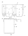
図1(a)は、本発明の請求項1に係るバッグインカートンにおける板紙製の外側カートンAの展開図であり、図1(b)は、その外側カートンAの内側に装着される透明乃至半透明又は不透明の柔軟な合成樹脂フィルム製の内側バッグB(袋)の平面図である。
【0028】
外側カートンAは図1(a)に示すように、正面板1の両側端に折目aを介して側面板2、2が連設され、一方側の側面板2の側端に折目bを介して背面板3が連設され、該背面板3の側端に折目cを介して貼着板4が連設されている。
【0029】
前記正面板1、側面板2、2、背面板3のそれぞれ下端には、折目dを介してそれぞれ底部5となる底面板6、7、8が連設されている。
【0030】
前記各々側面板2の下端の底面板7、7は折目aと平行な折目fにより二等分されている。
【0031】
内側バッグBは図1(b)に示すように、筒状の合成樹脂フィルム20により形成され、その上端開口部21と下端開口部22とを備え、その筒状フィルム20の上端開口部21内には、密封、開封、再封可能なジッパー23が取り付けられ、前記筒状フィルム20の偏平形状における水平方向の幅と、正面板1及び背面板3の幅とは、互いに略等しい幅となっている。なお、ジッパー23の構造は本発明においては特に限定するものではないが、一般的に公知のジッパーとして例えば直線凹溝の形成された凹溝テープと直線凸部の形成された凸テープとの凹凸嵌合方式によるジッパー23が適当である。
【0032】
図2に示すように、外側カートンAの正面板1上には、内側バッグBがそのジッパー23を取り付けた上端開口部21を底部5に対して反対側にして重ね合わせられて、その重ね合わせ内面が、部分的又は全面的に又はその重ね合わせ内面の外周に沿って互いに貼着されている。なお、この貼着方式は、本発明においては特に限定されるものではないが、例えば感熱接着剤、感圧接着剤(粘着剤)、感熱粘着剤などの接着剤を使用して行うことができる。また、接着剤の適用領域は、その全面領域、部分領域のいずれでもよく、またポンイト(点状)接着、線状接着などでもよい。また例えばホットメルト型の接着剤を使用することも可能である。
【0033】
図3に示すように、外側カートンAの正面板1上に重ね合わせた内側バッグBの上面には、一方の折目fを介して一方の側面板2の半側面板2bと背面板3とが折り返されて重ね合わせられている。
【0034】
続いて、図4に示すように、他方の折目fを介して他方の側面板2の半側面板2bが貼着板4上に折り返されて重ね合わせられて該貼着板4と半側面板2bとが貼着されている。
【0035】
またフィルム製の内側バッグBの外面を被覆するように四角形筒状側部10が形成されている。なお、この貼着方式は、本発明においては特に限定されるものではないが、例えば感熱接着剤、感圧接着剤(粘着剤)、感熱粘着剤などの接着剤を使用して行うことができる。また、接着剤の適用領域は、その全面領域、部分領域のいずれでもよく、またポンイト(点状)接着、線状接着などでもよい。また例えばホットメルト型の接着剤を使用することも可能である。
【0036】
本発明のバッグインカートンは、図4に示すように、外側カートンAの四角形筒状側部10により内側バッグBを被覆していて、立体的に組み立て形成する以前においては偏平形状となっている。
【0037】
図4に示す組み立て以前の偏平形状の本発明のバッグインカートンは、その両外側の二つ折りになっている側面板2、2を、折目f、fをカートン内方に押すことにより平坦にすることにより、図5に示すような角筒状に立ち起こすことができる。
【0038】
そして、外側カートンAの各々側面板2、2下端にある互いに対向する底面板7、7を、折目dを介して内側バッグBの下端開口部22を形成している筒状フィルム20と共にカートン内方に水平に折り曲げた後、正面板1と背面板3のそれぞれ下端の対向する底面板6、8を、筒状フィルム20と共にカートン内方に水平にその水平に折り曲げた底面板7、7上に折り重ねて、底面板7、7とその上に重ね合わせた底面板6とを貼着固定し、該底面板6とその上に重ね合わせた底面板8とを貼着固定して底部5が形成されて、本発明のバッグインカートンは立方体又は直方体形状となっている。
【0039】
なお、内側バッグBの少なくとも下端開口部22内面には、熱接着性の合成樹脂層(シーラント層)が形成されていて、貼着固定された前記底部5と共に折り込まれている内側バッグBの筒状フィルム20下端開口部は、その底部5の上下面(内外面)より加熱シール手段により加熱押圧されて密封状態にシールされている。なお、底部5の上面(内面)には、内側バッグBの筒状フィルム20上端開口部21に取り付けられているジッパー23を開封状態にして、その開封された上端開口部21よりバッグB内部に加熱シール手段(加熱押圧部材又は押圧受部材のいずれか一方)を介入させることにより底部5は加熱シールされている。
【0040】
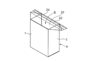
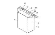
図24は、底部5を形成して立方体又は直方体形状となった外側カートンAと内側バッグBとにより構成された本発明のバッグインカートンであり、内側バッグBの筒状フィルム20上端開口部21に取り付けられているジッパー23を封鎖した状態を示し、本発明のバッグインカートンにおいては、図示するようにジッパー23の長手方向は外側カートンAの角筒状上端部の一辺に対して略平行な方向となっている。
【0041】
本発明のバッグインカートンの内側バッグBの筒状フィルム20上端開口部21に取り付けられたジッパー23より、さらに上方の筒状フィルム20最上端部には、図24に示すように内側バッグB内に液状物などの内容物を充填した後において加熱シールされて密封シール部24が形成されていて、バッグインカートンを開封する際は、まずジッパー23と密封シール部24との間に沿ってフィルム20を切り裂き、続いてジッパー23を開封することにより行う。そして、再封はそのジッパー23を用いて行うものである。
【0042】
本発明のバッグインカートンは、図24に示すように外側カートンAの各々側面板2、2の上端より内側バッグBの上端開口部21のフィルム20が、図7〜図8に示すように、側面板2、2の外面に重なるように三角形状に折り返されて、各々側面板2、2の外面にそのそれぞれ三角形状フィルム20を貼着固定することにより組み立てられている。
【0043】
側面板2と三角形状フィルム20との貼着方式としては、本発明においては特に限定されるものではないが、例えば、感熱接着剤、感圧接着剤(粘着剤)、感熱粘着剤などの接着剤を用いて行うことができ、側面板2と三角形状フィルム20との重ね合わせ内面における接着剤の適用領域は、その全面領域、部分領域のいずれでもよく、またポンイト(点状)接着、線状接着などでもよい。また例えばホットメルト型の接着剤を使用することも可能である。
【0044】
本発明の請求項2に係る発明のバッグインカートンを、実施の形態に従って以下に詳細に説明する。
【0045】
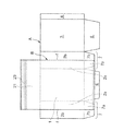
図9(a)は、本発明の請求項2に係るバッグインカートンにおける板紙製の外側カートンAの展開図であり、図9(b)は、その外側カートンAの内側に装着される透明乃至半透明又は不透明の柔軟な合成樹脂フィルム製の内側バッグB(袋)の平面図である。
【0046】
外側カートンAは図9(a)に示すように、正面板1の両側端に折目aを介して側面板2、2が連設され、一方側の側面板2の側端に折目bを介して背面板3が連設され、該背面板3の側端に折目cを介して貼着板4が連設されている。
【0047】
前記正面板1、側面板2、2、背面板3のそれぞれ下端には、折目dを介してそれぞれ底面板6、7、8が連設され、側面板2、2の上端には、折目eを介してそれぞれ直角二等辺三角形面板9、9(三角フラップ)が連設されている。
【0048】
前記各々側面板2と、その上端の三角形面板9と、その下端の底面板7、7は折目aと平行な折目fにより二等分されている。
【0049】
内側バッグBは図9(b)に示すように、筒状の合成樹脂フィルム20により形成され、その上端開口部21と下端開口部22とを備え、その筒状フィルム20の上端開口部21内には、密封、開封、再封可能なジッパー23が取り付けられ、前記筒状フィルム20の偏平形状における水平方向の幅と、正面板1及び背面板3の幅とは、互いに略等しい幅となっている。なお、ジッパー23の構造は本発明においては特に限定するものではないが、一般的に公知のジッパーとして例えば直線凹溝の形成された凹溝テープと直線凸部の形成された凸テープとの凹凸嵌合方式によるジッパー23が適当である。
【0050】
図10に示すように、外側カートンAの正面板1上には、内側バッグBがそのジッパー23を取り付けた上端開口部21を三角形面板9側にして重ね合わせられて、その重ね合わせ内面が、部分的又は全面的に又はその重ね合わせ内面の外周に沿って互いに貼着されている。なお、この貼着方式は、本発明においては特に限定されるものではないが、例えば、感熱接着剤、感圧接着剤(粘着剤)、感熱粘着剤などの接着剤を使用して行うことができる。また、接着剤の適用領域は、その全面領域、部分領域のいずれでもよく、またポンイト(点状)接着、線状接着などでもよい。また例えばホットメルト型の接着剤を使用することも可能である。
【0051】
図11に示すように、外側カートンAの正面板1上に重ね合わせた内側バッグBの上面には、一方の折目fを介して一方の側面板2の半側面板2bと背面板3とが折り返されて重ね合わせられている。
【0052】
続いて、図12に示すように、他方の折目fを介して他方の側面板2の半側面板2bが貼着板4上に折り返されて重ね合わせられて該貼着板4と半側面板2bとが貼着されている。
【0053】
また各々側面板2、2の上端にあるそれぞれ三角形面板9、9の内面は、内側バッグB側に貼着されて、フィルム製の内側バッグBの外面を被覆するように四角形筒状側部10が形成されている。なお、この貼着方式は、本発明においては特に限定されるものではないが、例えば感熱接着剤、感圧接着剤(粘着剤)、感熱粘着剤などの接着剤を使用して行うことができる。また、接着剤の適用領域は、その全面領域、部分領域のいずれでもよく、またポンイト(点状)接着、線状接着などでもよい。また例えばホットメルト型の接着剤を使用することも可能である。
【0054】
本発明のバッグインカートンは、図12に示すように、外側カートンAの四角形筒状側部10により内側バッグBを被覆していて、立体的に組み立て形成する以前においては偏平形状となっている。
【0055】
図12に示す組み立て以前の偏平形状の本発明のバッグインカートンは、その両外側の二つ折りになっている側面板2、2を、折目f、fをカートン内方に押すことにより平坦にすることにより、図13に示すように外側カートンAと、内側バッグBの筒状の合成樹脂フィルム20とを角筒状体に立ち起こすことができる。筒状の合成樹脂フィルム20はジッパー23を備えた上端開口部21と、後において外側カートンAの底面板6、7、7、8により被覆される下端開口部22とを備え、角筒状に立ち起こした後は、上端開口部21側又は下端開口部22側のいずれか一方の開口部を密封シールした後に、他方の開口部を充填用開口部として内容物を充填し、その後、前記充填用開口部(ジッパー側であればジッパー23)を封鎖し密封シールする。なお、図12に示す偏平形状のバッグインカートンにおいては、予めジッパー23を閉じ、その上端開口部21の上縁をシールして密封するか、あるいは予め閉じた状態でバッグを作製しておくこともできる。この場合、内容物の充填は下端開口部22から行うこととなる。
【0056】
上記バッグBの下端開口部22の密封シールと、外側カートンAの底面板6、7、7、8の封鎖は、例えば、バッグの下端開口部22を、図の左右方向に引っ張りながら表裏を重ね合わせるようにして、重ね合わせた開口端縁を脱気しながら偏平にヒートシールすることにより密封し、当該偏平シール部分を底面と平行になるように折り倒し、次いで底面板7、7を折目dを介して上記シールされたバッグ下端のフィルムと共にカートン内方に水平に折り曲げた後、底面板7、7の所定位置に接着剤(例えばホットメルト接着剤)を塗布し、正面板1と背面板3のそれぞれ下端の対向する底面板6、8を、カートン内方に水平にして、先に折り曲げた前記底面板7、7上に折り重ねて接着固定することにより、行うことができる。なお、接着剤は、必要に応じて底面板6(又は8)に塗布することもできる。
【0057】
なお、内側バッグBの少なくとも下端開口部22内面には、熱接着性の合成樹脂層(シーラント層)が形成されていて、下端開口部22の上記ヒートシールが可能となっている。
【0058】
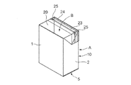
図14は、底部5を形成して立方体又は直方体形状となった外側カートンAと内側バッグBとにより構成された本発明のバッグインカートンであり、内側バッグBの筒状フィルム20上端開口部21に取り付けられているジッパー23を封鎖した状態を示し、本発明のバッグインカートンにおいては、図示するようにジッパー23の長手方向は外側カートンAの角筒状上端部の一辺に対して略平行な方向となっている。
【0059】
本発明のバッグインカートンの内側バッグBの筒状フィルム20上端開口部21に取り付けられたジッパー23より、さらに上方の筒状フィルム20最上端部には、加熱加圧にて密封シールされ密封シール部24が形成されていて、バッグインカートンを開封する際は、まずジッパー23と密封シール部24との間に沿ってフィルム20を切り裂き、続いてジッパー23を開封することにより行う。そして、再封はそのジッパー23を用いて行うものである。
【0060】
本発明のバッグインカートンは、図14に示すように外側カートンAの各々側面板2、2の上端にあるそれぞれ三角形面板9、9を、折目eを介してその内面に貼着している内側バッグBのフィルム20と共に、図15〜図16に示すように側面板2、2の外面に重なるように折り返されて、各々側面板2、2の外面にそれぞれ三角形面板9、9を貼着固定することにより組み立てられている。
【0061】
側面板2と三角形面板9との貼着方式としては、本発明においては特に限定されるものではないが、例えば、感熱接着剤、感圧接着剤(粘着剤)、感熱粘着剤などの接着剤を用いて行うことができ、側面板2と三角形面板9との重ね合わせ内面における接着剤の適用領域は、その全面領域、部分領域のいずれでもよく、またポンイト(点状)接着、線状接着などでもよい。また例えばホットメルト型の接着剤を使用することも可能である。
【0062】
本発明の請求項3、請求項4に係る発明のバッグインカートンの実施の形態としては、例えば図17〜図18に示すように、外側カートンAの各々側面板2、2上端にあるそれぞれ三角形面板9、9の頂角先端部9c部分領域(一点鎖線より矢印方向側の領域)には、内側バッグB側に貼着されない非貼着領域が形成され、頂角先端部9c部分以外の領域(一点鎖線より矢印方向と反対側の領域)には、内側バッグB側に貼着された貼着領域が形成され、そして外側カートンAの各々側面板2、2には、予めカートン展開図(図9(a)のブランク図)の状態において、図17に示すように切込部11が刻切されている。
【0063】
なお、この貼着方式は、本発明においては特に限定されるものではないが、例えば感熱接着剤、感圧接着剤(粘着剤)、感熱粘着剤などの接着剤を使用して行うことができ、また、接着剤の適用領域は、その全面領域、部分領域のいずれでもよく、また、ポンイト(点状)接着、線状接着などでもよい。また例えばホットメルト型の接着剤を使用することも可能である。
【0064】
そして、図18に示すように、三角形面板9、9の頂角先端部9c部分を各々側面板2、2の切込部11内に差し込むことにより、内側バッグBのフィルム20を貼着した三角形面板9、9を接着剤や粘着剤を使用しないで各々側面板2、2に固定するようにしてもよい。また、前記切込部11内に三角形面板9を差し込み固定する際には、必要に応じて接着剤や粘着剤(両面粘着テープやシート)を併用してもよく、切込部11近傍の外側カートン側面板2と三角形面板9との重ね合わせ内面に前記接着剤や粘着剤を適用するものである。
【0065】
次に、本発明の請求項5に係る発明のバッグインカートンを、実施の形態に従って以下に詳細に説明する。
【0066】
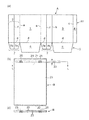
図19(a)は、本発明の請求項5に係るバッグインカートンにおける板紙製の外側カートンAの展開図であり、図19(b)は、その外側カートンAの内側に装着される透明乃至半透明、又は不透明の柔軟な合成樹脂フィルム製の内側バッグB(袋)の平面図、図19(c)は、図19(b)のL−L断面図である。
【0067】
外側カートンAは図19(a)に示すように、正面板1の両側端に折目aを介して側面板2、2が連設され、一方側の側面板2の側端に折目bを介して背面板3が連設され、該背面板3の側端に折目cを介して貼着板4が連設されている。
【0068】
前記正面板1、側面板2、2、背面板3のそれぞれ下端には、折目dを介してそれぞれ底面板6、7、8による底部5が連設されている。
【0069】
前記各々側面板2と、その下端の底面板7、7は折目aと平行な折目fにより二等分されている。
【0070】
内側バッグBは図19(b)に示すように、筒状の合成樹脂フィルム20により形成されていて、その上端開口部21と下端開口部22とを備え、その筒状フィルム20の上端開口部21内には、密封、開封、再封可能なジッパー23が取り付けられている。
【0071】
前記筒状フィルム20の偏平形状における水平方向の幅は、正面板1(又は背面板3)の幅と、その両側の半側面板2aと2aの幅の合計の幅に略等しい幅となっている。
【0072】
そして、内側バッグBは図19(b)の平面図に示すように、ジッパー23の長手方向の両端側に、筒状フィルム上より凹凸エンボスして形成されたジッパー折目部25、25を備えている。
【0073】
ジッパー折目部25、25は図19(b)及び図19(c)に示す図19(b)のL−L断面図に示すように、筒状フィルム20の上端開口部21内に取り付けたジッパー23を、その筒状フィルム20の一面から他面側(図中フィルム20の上面から下面側)に向かって凹凸エンボス用雄型を他面側の凹凸エンボス用雌型に対して押圧動作(フィルム溶融温度以下の加熱温度(ガラス転移点以下の温度)にて加熱しながら押圧又は非加熱押圧動作)して、筒状フィルム20と共に例えばジグザグ状若しくは波状に凹凸エンボス加工することにより形成されている。
【0074】
これによって内側バッグBのジッパー23の両端側は、折目部25、25を介して凹凸エンボス用雄型側(筒状フィルム20上面側)に容易に折り曲げることができるようになっている。
【0075】
図20に示すように、外側カートンAの正面板1上には、内側バッグBがそのジッパー23を取り付けた上端開口部21を底部5と反対側にして重ね合わせられて、その重ね合わせ内面が、部分的又は全面的に又はその重ね合わせ内面の外周に沿って互いに貼着されている。なお、この貼着方式は、本発明においては特に限定されるものではないが、例えば、感熱接着剤、感圧接着剤(粘着剤)、感熱粘着剤などの接着剤を使用して行うことができる。また、接着剤の適用領域は、その全面領域、部分領域のいずれでもよく、またポンイト(点状)接着、線状接着などでもよい。また例えばホットメルト型の接着剤を使用することも可能である。
【0076】
図21に示すように、外側カートンAの正面板1上に重ね合わせた内側バッグBの上面には、一方の折目fを介して一方の側面板2の半側面板2bと背面板3とが折り返されて重ね合わせられている。
【0077】
続いて、図22に示すように、他方の折目fを介して他方の側面板2の半側面板2bが貼着板4上に折り返されて重ね合わせられて該貼着板4と半側面板2bとが貼着されている。
【0078】
またフィルム製の内側バッグBの外面を被覆するように四角形筒状側部10が形成されている。なお、この貼着方式は、本発明においては特に限定されるものではないが、例えば感熱接着剤、感圧接着剤(粘着剤)、感熱粘着剤などの接着剤を使用して行うことができる。また、接着剤の適用領域は、その全面領域、部分領域のいずれでもよく、またポンイト(点状)接着、線状接着などでもよい。また例えばホットメルト型の接着剤を使用することも可能である。
【0079】
本発明のバッグインカートンは、図22に示すように、外側カートンAの四角形筒状側部10により内側バッグBを被覆していて、立体的に組み立て形成する以前においては偏平形状となっている。
【0080】
図22に示す組み立て以前の偏平形状の本発明のバッグインカートンは、その両外側の二つ折りになっている側面板2、2を、折目f、fをカートン内方に押すことにより平坦にすることにより、図23に示すように外側カートンAと、内側バッグBの筒状の合成樹脂フィルム20とを角筒状体に立ち起こすことができる。筒状の合成樹脂フィルム20はジッパー23を備えた上端開口部21と、後において外側カートンAの底面板6、7、7、8により被覆される下端開口部22とを備え、角筒状に立ち起こした後は、上端開口部21側又は下端開口部22側のいずれか一方の開口部を密封シールした後に、他方の開口部を充填用開口部として内容物を充填し、その後、前記充填用開口部(ジッパー側であればジッパー23)を封鎖し密封シールする。なお、図22に示す偏平形状のバッグインカートンにおいては、予めジッパー23を閉じ、その上端開口部21の上縁をシールして密封するか、あるいは予め閉じた状態でバッグを作製しておくこともできる。この場合、内容物の充填は下端開口部22から行うこととなる。
【0081】
上記バッグBの下端開口部22の密封シールと、外側カートンAの底面板6、7、7、8の封鎖は、例えば、バッグの下端開口部22を、図の左右方向に引っ張りながら表裏を重ね合わせるようにして、重ね合わせた開口端縁を脱気しながら偏平にヒートシールすることにより密封し、当該偏平シール部分を底面と平行になるように折り倒し、次いで底面板7、7を折目dを介して上記シールされたバッグ下端のフィルムと共にカートン内方に水平に折り曲げた後、底面板7、7の所定位置に接着剤(例えばホットメルト接着剤)を塗布し、正面板1と背面板3のそれぞれ下端の対向する底面板6、8を、カートン内方に水平にして、先に折り曲げた前記底面板7、7上に折り重ねて接着固定することにより、行うことができる。なお、接着剤は、必要に応じて底面板6(又は8)に塗布することもできる。
【0082】
なお、内側バッグBの少なくとも下端開口部22内面には、熱接着性の合成樹脂層(シーラント層)が形成されていて、下端開口部22の上記ヒートシールが可能となっている。
【0083】
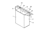
図24は、底部5を形成して立方体又は直方体形状となった外側カートンAと内側バッグBとにより構成された本発明のバッグインカートンであり、内側バッグBの筒状フィルム20の上端開口部21に取り付けられているジッパー23を封鎖した状態を示し、本発明のバッグインカートンにおいては、図示するようにジッパー23の長手方向は外側カートンAの角筒状上端部の一辺に対して略平行な方向となっている。
【0084】
本発明のバッグインカートンの内側バッグBの筒状フィルム20上端開口部21に取り付けられたジッパー23より、さらに上方の筒状フィルム20最上端部には、図24に示すように加熱加圧にて密封シールされ密封シール部24が形成されていて、バッグインカートンを開封する際は、まずジッパー23と密封シール部24との間に沿ってフィルム20を切り裂き、続いてジッパー23を開封することにより行う。そして、再封はそのジッパー23を用いて行うものである。
【0085】
本発明のバッグインカートンは、図24に示すように外側カートンAの各々側面板2、2の上端より、内側バッグBの上端開口部21のフィルム20を、図25〜図26に示すように側面板2、2の外面に重なるように三角形状に直角に折り返して、各々側面板2、2の外面に、その三角形状フィルム20を貼着固定することにより立方体又は直方体形状に組み立てられている。
【0086】
本発明のバッグインカートンにおいては、内側バッグBの上端開口部21の三角形状フィルム20が側面板2、2の外面に重なるように折り返される際に、筒状フィルム20上端開口部21に取り付けられた比較的剛性のあるジッパー23は、折目部25、25を介して、容易にその両端側が直角に折り曲げられ、折り曲げる時にその折目部25、25の間のジッパー23の長手方向が湾曲することなく直線的に、内側バッグBの上面部を平坦に保持した状態で、外側カートンAの側面板2、2の外面に重なるように直角に折り曲げられる。
【0087】
側面板2と三角形面板9との貼着方式としては、本発明においては特に限定されるものではないが、例えば、感熱接着剤、感圧接着剤(粘着剤)、感熱粘着剤などの接着剤を用いて行うことができ、側面板2と三角形面板9との重ね合わせ内面における接着剤の適用領域は、その全面領域、部分領域のいずれでもよく、またポンイト(点状)接着、線状接着などでもよい。また例えばホットメルト型の接着剤を使用することも可能である。
【0088】
次に本発明の請求項6に係る発明のバッグインカートンを、実施の形態に従って以下に詳細に説明する。
【0089】
図27(a)は、本発明の請求項6に係るバッグインカートンにおける板紙製の外側カートンAの展開図であり、図27(b)は、その外側カートンAの内側に装着される透明乃至半透明、又は不透明の柔軟な合成樹脂フィルム製の内側バッグB(袋)の平面図、図27(c)は、図27(b)のL−L断面図である。
【0090】
外側カートンAは図27(a)に示すように、正面板1の両側端に折目aを介して側面板2、2が連設され、一方側の側面板2の側端に折目bを介して背面板3が連設され、該背面板3の側端に折目cを介して貼着板4が連設されている。
【0091】
前記正面板1、側面板2、2、背面板3のそれぞれ下端には、折目dを介してそれぞれ底面板6、7、8が連設され、側面板2、2の上端には、折目eを介してそれぞれ直角二等辺三角形面板9、9(三角フラップ)が連設されている。
【0092】
前記各々側面板2と、その上端の三角形面板9と、その下端の底面板7、7は折目aと平行な折目fにより二等分されている。
【0093】
内側バッグBは図27(b)に示すように、筒状の合成樹脂フィルム20により形成されていて、その上端開口部21と下端開口部22とを備え、その筒状フィルム20の上端開口部21内には、密封、開封、再封可能なジッパー23が取り付けられている。
【0094】
前記筒状フィルム20の偏平形状における水平方向の幅は、正面板1(又は背面板3)の幅と、その両側の半側面板2aと2aの幅の合計の幅に略等しい幅となっている。
【0095】
そして、内側バッグBは図27(b)の平面図に示すように、ジッパー23の長手方向の両端側に、筒状フィルム上より凹凸エンボスして形成されたジッパー折目部25、25を備えている。
【0096】
ジッパー折目部25、25は図27(b)及び図27(c)に示す図27(b)のL−L断面図に示すように、筒状フィルム20の上端開口部21内に取り付けたジッパー23を、その筒状フィルム20の一面から他面側(図中フィルム20の上面から下面側)に向かって凹凸エンボス用雄型を他面側の凹凸エンボス用雌型に対して押圧動作(フィルム溶融温度以下の加熱温度(ガラス転移点以下の温度)にて加熱しながら押圧又は非加熱押圧動作)して、筒状フィルム20と共に例えばジグザグ状若しくは波状に凹凸エンボス加工することにより形成されている。
【0097】
これによって内側バッグBのジッパー23の両端側は、折目部25、25を介して凹凸エンボス用雄型側(筒状フィルム20上面側)に容易に折り曲げることができるようになっている。
【0098】
図28に示すように、外側カートンAの正面板1上には、内側バッグBがそのジッパー23を取り付けた上端開口部21を三角形面板9側にして重ね合わせられて、その重ね合わせ内面が、部分的又は全面的に又はその重ね合わせ内面の外周に沿って互いに貼着されている。なお、この貼着方式は、本発明においては特に限定されるものではないが、例えば、感熱接着剤、感圧接着剤(粘着剤)、感熱粘着剤などの接着剤を使用して行うことができる。また、接着剤の適用領域は、その全面領域、部分領域のいずれでもよく、またポンイト(点状)接着、線状接着などでもよい。また例えばホットメルト型の接着剤を使用することも可能である。
【0099】
図29に示すように、外側カートンAの正面板1上に重ね合わせた内側バッグBの上面には、一方の折目fを介して一方の側面板2の半側面板2bと背面板3とが折り返されて重ね合わせられている。
【0100】
続いて、図30に示すように、他方の折目fを介して他方の側面板2の半側面板2bが貼着板4上に折り返されて重ね合わせられて該貼着板4と半側面板2bとが貼着されている。
【0101】
また各々側面板2、2の上端にあるそれぞれ三角形面板9、9の内面は、内側バッグB側に貼着されて、フィルム製の内側バッグBの外面を被覆するように四角形筒状側部10が形成されている。なお、この貼着方式は、本発明においては特に限定されるものではないが、例えば感熱接着剤、感圧接着剤(粘着剤)、感熱粘着剤などの接着剤を使用して行うことができる。また、接着剤の適用領域は、その全面領域、部分領域のいずれでもよく、またポンイト(点状)接着、線状接着などでもよい。また例えばホットメルト型の接着剤を使用することも可能である。
【0102】
本発明のバッグインカートンは、図30に示すように、外側カートンAの四角形筒状側部10により内側バッグBを被覆していて、立体的に組み立て形成する以前においては偏平形状となっている。
【0103】
図30に示す組み立て以前の偏平形状の本発明のバッグインカートンは、その両外側の二つ折りになっている側面板2、2を、折目f、fをカートン内方に押すことにより平坦にすることにより、図31に示すような角筒状に立ち起こすことができる。
【0104】
そして、外側カートンAの各々側面板2、2下端にある互いに対向する底面板7、7を、折目dを介して内側バッグBの下端開口部22を形成している筒状フィルム20と共にカートン内方に水平に折り曲げた後、正面板1と背面板3のそれぞれ下端の対向する底面板6、8を、筒状フィルム20と共にカートン内方に水平にその水平に折り曲げた底面板7、7上に折り重ねて、底面板7、7とその上に重ね合わせた底面板6とを貼着固定し、該底面板6とその上に重ね合わせた底面板8とを貼着固定して底部5が形成されて、本発明のバッグインカートンは立方体又は直方体形状となっている。
【0105】
なお、内側バッグBの少なくとも下端開口部22内面には、熱接着性の合成樹脂層(シーラント層)が形成されていて、貼着固定された前記底部5と共に折り込まれている内側バッグBの筒状フィルム20下端開口部は、その底部5の上下面(内外面)より加熱シール手段により加熱押圧されて密封状態にシールされている。なお、底部5の上面(内面)には、内側バッグBの筒状フィルム20上端開口部21に取り付けられているジッパー23を開封状態にして、その開封された上端開口部21よりバッグB内部に加熱シール手段(加熱押圧部材又は押圧受部材のいずれか一方)を介入させることにより底部5は加熱シールされている。
【0106】
図32は、底部5を形成して立方体又は直方体形状となった外側カートンAと内側バッグBとにより構成された本発明のバッグインカートンであり、内側バッグBの筒状フィルム20上端開口部21に取り付けられているジッパー23を封鎖した状態を示し、本発明のバッグインカートンにおいては、図示するようにジッパー23の長手方向は外側カートンAの角筒状上端部の一辺に対して略平行な方向となっている。
【0107】
本発明のバッグインカートンの内側バッグBの筒状フィルム20上端開口部21に取り付けられたジッパー23より、さらに上方の筒状フィルム20最上端部には、図34に示すように加熱加圧にて密封シールされ密封シール部24が形成されていて、バッグインカートンを開封する際は、まずジッパー23と密封シール部24との間に沿ってフィルム20を切り裂き、続いてジッパー23を開封することにより行う。そして、再封はそのジッパー23を用いて行うものである。
【0108】
本発明のバッグインカートンは、図32に示すように外側カートンAの各々側面板2、2の上端にあるそれぞれ三角形面板9、9が、折目eを介してその内面に貼着している内側バッグBのフィルム20と共に、図33〜図34に示すように、側面板2、2の外面に重なるように直角に折り返されて、各々側面板2、2の外面にそれぞれ三角形面板9、9を貼着固定することにより組み立てられている。
【0109】
本発明のバッグインカートンにおいては、三角形面板9、9が内側バッグBのフィルム20と共に側面板2、2の外面に重なるように折り返される際に、筒状フィルム20上端開口部21に取り付けられた比較的剛性のあるジッパー23は折目部25、25を介してその両端側が直角に折り曲げられ、折り曲げる時にその折目部25、25の間のジッパー23の長手方向は湾曲することなく、内側バッグBの上面部を平坦に保持した状態で外側カートンAの側面板2、2の外面に重なるように直角に折り曲げられる。
【0110】
側面板2と三角形面板9との貼着方式としては、本発明においては特に限定されるものではないが、例えば、感熱接着剤、感圧接着剤(粘着剤)、感熱粘着剤などの接着剤を用いて行うことができ、側面板2と三角形面板9との重ね合わせ内面における接着剤の適用領域は、その全面領域、部分領域のいずれでもよく、またポンイト(点状)接着、線状接着などでもよい。また例えばホットメルト型の接着剤を使用することも可能である。
【0111】
本発明の請求項7、請求項8に係る発明のバッグインカートンの実施の形態としては、例えば、図35〜図36に示すように、外側カートンAの各々側面板2、2上端にあるそれぞれ三角形面板9、9の頂角先端部9c部分領域(一点鎖線より矢印方向側の領域)には、内側バッグB側に貼着されない非貼着領域が形成され、頂角先端部9c部分以外の領域(一点鎖線より矢印方向と反対側の領域)には、内側バッグB側に貼着された貼着領域が形成され、そして外側カートンAの各々側面板2、2には、予めカートン展開図(図27(a)のブランク図)の状態において、図35に示すように切込部11が刻切されている。
【0112】
なお、この貼着方式は、本発明においては特に限定されるものではないが、例えば感熱接着剤、感圧接着剤(粘着剤)、感熱粘着剤などの接着剤を使用して行うことができ、また、接着剤の適用領域は、その全面領域、部分領域のいずれでもよく、また、ポンイト(点状)接着、線状接着などでもよい。また例えばホットメルト型の接着剤を使用することも可能である。
【0113】
そして、図36に示すように、三角形面板9、9の頂角先端部9c部分を各々側面板2、2の切込部11内に差し込むことにより、内側バッグBのフィルム20を貼着した三角形面板9、9を接着剤や粘着剤を使用しないで各々側面板2、2に固定するようにしてもよい。また、前記切込部11内に三角形面板9を差し込み固定する際には、必要に応じて接着剤や粘着剤(両面粘着テープやシート)を併用してもよく、切込部11近傍の外側カートン側面板2と三角形面板9との重ね合わせ内面に前記接着剤や粘着剤を適用するものである。
【0114】
【発明の効果】
本発明のバッグインカートンは、比較的軽量の内容物をバッグインカートン型の容器を用いて充填包装する場合に、それに対応した十分な強度を以て、従来のような強度のあるバッグインカートンと同程度の機能性と密封性と適正な強度を備えることができ、外観的に過剰包装的でない省資源化した容器を提供することができる効果がある。
【0115】
また、本発明のバッグインカートンは、外側カートンの上端から外側に内側バッグを三角形状に外側カートンの側面板に直角に折り重ねる際に、内側バッグのジッパー折目部を介して折り曲げることができ、折り曲げる時に、その折目部間のジッパー長手方向が外側に湾曲したり膨らんだりせずに直線的に内側バッグの上面部を平坦に保持した状態で直角に折り曲げることができ、外観的に綺麗で、すっきりした良好な形状の立方体、直方体形状のバッグインカートンを提供できるものである。
【図面の簡単な説明】
【図1】(a)は本発明の請求項1に係る発明のバッグインカートンを構成する外側カートンの展開図、(b)はそのバッグインカートンを構成する内側バッグの平面図。
【図2】本発明の請求項1に係る発明のバッグインカートンを構成する外側カートン上に内側バッグを重ね合わせた状態を示す平面図。
【図3】本発明の請求項1に係る発明のバッグインカートンを構成する外側カートン上に内側バッグを重ね合わせ組み立てられる途中の状態を示す平面図。
【図4】本発明の請求項1に係る発明のバッグインカートンを構成する外側カートン上に内側バッグを重ね合わせ組み立てられる途中の状態を示す平面図。
【図5】本発明の請求項1に係る発明のバッグインカートンを構成する外側カートン内に内側バッグを装着して組み立てられる途中の角筒状態を示す全体斜視図。
【図6】本発明の請求項1に係る発明のバッグインカートンを構成する外側カートン内に内側バッグを装着し底部を形成して組み立てられる途中の状態を示す全体斜視図。
【図7】本発明の請求項1に係る発明のバッグインカートンを構成する外側カートン内に内側バッグを装着し底部を形成して組み立てられる途中の状態を示す全体斜視図。
【図8】本発明の請求項1に係る発明のバッグインカートンを構成する外側カートン内に内側バッグを装着し底部を形成して組み立てられた組み立て完成斜視図。
【図9】(a)は本発明の請求項2に係る発明のバッグインカートンを構成する外側カートンの展開図、(b)はそのバッグインカートンを構成する内側バッグの平面図。
【図10】本発明の請求項2に係る発明のバッグインカートンを構成する外側カートン上に内側バッグを重ね合わせた状態を示す平面図。
【図11】本発明の請求項2に係る発明のバッグインカートンを構成する外側カートン上に内側バッグを重ね合わせ組み立てられる途中の状態を示す平面図。
【図12】本発明の請求項2に係る発明のバッグインカートンを構成する外側カートン上に内側バッグを重ね合わせ組み立てられる途中の状態を示す平面図。
【図13】本発明の請求項2に係る発明のバッグインカートンを構成する外側カートン内に内側バッグを装着して組み立てられる途中の角筒状態を示す全体斜視図。
【図14】本発明の請求項2に係る発明のバッグインカートンを構成する外側カートン内に内側バッグを装着し底部を形成して組み立てられる途中の状態を示す全体斜視図。
【図15】本発明の請求項2に係る発明のバッグインカートンを構成する外側カートン内に内側バッグを装着し底部を形成して組み立てられる途中の状態を示す全体斜視図。
【図16】本発明の請求項2に係る発明のバッグインカートンを構成する外側カートン内に内側バッグを装着し底部を形成して組み立てられた組み立て完成斜視図。
【図17】本発明の請求項2に係る発明のバッグインカートンを構成する外側カートン内に内側バッグを装着し底部を形成して組み立てられる途中の状態を示す他の実施の形態における全体斜視図。
【図18】本発明の請求項2に係る発明のバッグインカートンを構成する外側カートン内に内側バッグを装着し底部を形成して組み立てられた他の実施の形態における組み立て完成斜視図。
【図19】(a)は本発明の請求項1に係る発明のバッグインカートンを構成する外側カートンの展開図、(b)はそのバッグインカートンを構成する内側バッグの平面図、(c)はそのバッグインカートンを構成する内側バッグのL−L断面図。
【図20】本発明の請求項1に係る発明のバッグインカートンを構成する外側カートン上に内側バッグを重ね合わせた状態を示す平面図。
【図21】本発明の請求項1に係る発明のバッグインカートンを構成する外側カートン上に内側バッグを重ね合わせ組み立てられる途中の状態を示す平面図。
【図22】本発明の請求項1に係る発明のバッグインカートンを構成する外側カートン上に内側バッグを重ね合わせ組み立てられる途中の状態を示す平面図。
【図23】本発明の請求項1に係る発明のバッグインカートンを構成する外側カートン内に内側バッグを装着して組み立てられる途中の角筒状態を示す全体斜視図。
【図24】本発明の請求項1に係る発明のバッグインカートンを構成する外側カートン内に内側バッグを装着し底部を形成して組み立てられる途中の状態を示す全体斜視図。
【図25】本発明の請求項1に係る発明のバッグインカートンを構成する外側カートン内に内側バッグを装着し底部を形成して組み立てられる途中の状態を示す全体斜視図。
【図26】本発明の請求項1に係る発明のバッグインカートンを構成する外側カートン内に内側バッグを装着し底部を形成して組み立てられた組み立て完成斜視図。
【図27】(a)は本発明の請求項2に係る発明のバッグインカートンを構成する外側カートンの展開図、(b)はそのバッグインカートンを構成する内側バッグの平面図、(c)はそのバッグインカートンを構成する内側バッグのL−L断面図。
【図28】本発明の請求項2に係る発明のバッグインカートンを構成する外側カートン上に内側バッグを重ね合わせた状態を示す平面図。
【図29】本発明の請求項2に係る発明のバッグインカートンを構成する外側カートン上に内側バッグを重ね合わせ組み立てられる途中の状態を示す平面図。
【図30】本発明の請求項2に係る発明のバッグインカートンを構成する外側カートン上に内側バッグを重ね合わせ組み立てられる途中の状態を示す平面図。
【図31】本発明の請求項2に係る発明のバッグインカートンを構成する外側カートン内に内側バッグを装着して組み立てられる途中の角筒状態を示す全体斜視図。
【図32】本発明の請求項2に係る発明のバッグインカートンを構成する外側カートン内に内側バッグを装着し底部を形成して組み立てられる途中の状態を示す全体斜視図。
【図33】本発明の請求項2に係る発明のバッグインカートンを構成する外側カートン内に内側バッグを装着し底部を形成して組み立てられる途中の状態を示す全体斜視図。
【図34】本発明の請求項2に係る発明のバッグインカートンを構成する外側カートン内に内側バッグを装着し底部を形成して組み立てられた組み立て完成斜視図。
【図35】本発明の請求項2に係る発明のバッグインカートンを構成する外側カートン内に内側バッグを装着し底部を形成して組み立てられる途中の状態を示す他の実施の形態における全体斜視図。
【図36】本発明の請求項2に係る発明のバッグインカートンを構成する外側カートン内に内側バッグを装着し底部を形成して組み立てられた他の実施の形態における組み立て完成斜視図。
【符号の説明】
A…外側カートン B…内側バッグ
1…正面板 2…側面板 3…背面板 4…貼着板 5…底部
6、7、8…底面板 9…三角面板(三角フラップ)
10…四角形筒状側部 11…切込部
20…筒状フィルム 21…上端開口部 22…下端開口部 23…ジッパー
24…密封シール部 25…ジッパー折目部
[0001]
BACKGROUND OF THE INVENTION
The present invention relates to a bag-in carton, particularly suitable for packaging lightweight items, in which a flexible plastic film sealing bag is mounted in a paperboard cube or rectangular parallelepiped carton.
[0002]
[Prior art]
Conventionally, a container called a bag-in-carton (bag-in-box) is well known as a sealed packaging container in which a sealing bag made of a flexible plastic film is installed in a paperboard cube or rectangular parallelepiped carton. It has been.
[0003]
This bag-in-carton is generally a plastic film sealing bag (pouch) loaded inside a cubic or rectangular parallelepiped carton (paper box) formed of paperboard or cardboard sheet. The outer surface of the bag filled with the liquid contents is adhered to the inner surface of the carton so as to follow the inner surface of the carton, so that it can withstand the bursting of the filled contents from the inside of the bag. The bag is covered and protected from the outside.
[0004]
In addition, a spout (cap) and a cap are attached to the bag, and the bag has a function that allows the contents to be injected, poured out, opened, and resealed.
[0005]
The carton (box) that covers and protects the bag of this bag-in-carton has a box shape like a normal cardboard case or paperboard case in appearance, so that it can sufficiently withstand the internal pressure of the bag due to the filling contents. Further, the paper box has a strong strength so as to sufficiently withstand the stacked load, and a paper box having sufficient strength corresponding to the weight of the contents filled in the bag is used.
[0006]
[Problems to be solved by the invention]
Such a bag-in-carton type container is usually used for filling and packaging of a liquid content having a relatively heavy weight of, for example, 10 kg to 20 kg or more. In appearance, there is an impression as a so-called overpackaging container.
[0007]
Therefore, when filling and packaging relatively lightweight contents using a bag-in-carton type container, it is sufficient that there is sufficient strength corresponding to that, and the same functionality, sealing performance and strength as bag-in-carton. It is desirable to use a container that is not excessively packaged in appearance.
[0008]
An object of the present invention is to provide a container that is not excessively packaged in appearance while having the same level of functionality, sealing performance and strength as a bag-in-carton (bag-in-box).
[0009]
[Means for Solving the Problems]
The invention according to claim 1 of the present invention is In a bag-in carton consisting of a paperboard outer carton having a cubic or rectangular parallelepiped shape and a film inner bag in close contact with the inner surface of the carton, Attached to the outer peripheral surface of the tubular film Consists of opposed front and back plates and a pair of opposed side plates It is covered with a rectangular cylindrical side and a bottom plate connected to one end of the cylindrical side. Said One end opening of the tubular film The A pair of opposing side directions are placed in the bottom part that is bent and adhered together with the bottom plate and sealed and the other end opening of the tubular film exposed to the outside of the other end opening of the cylindrical side part. Opening longitudinal direction A sealing zipper attached as a sealing seal part formed along the other end opening end in parallel with the sealing zipper, and the cylindrical film on the other end opening side is the pair of opposite side parts Are folded back outwardly in a triangular shape along the upper end of each of the pair, and fixed to the pair of opposing sides, No top surface A bag-in carton comprising a paperboard outer carton having a cubic or rectangular parallelepiped shape and a film inner bag in close contact with the inner surface of the carton.
[0010]
Next, the invention according to claim 2 of the present invention is as follows: In a bag-in carton consisting of a paperboard outer carton having a cubic or rectangular parallelepiped shape and a film inner bag in close contact with the inner surface of the carton, Attached to the outer peripheral surface of the tubular film Consists of opposed front and back plates and a pair of opposed side plates It is covered with a rectangular cylindrical side and a bottom plate connected to one end of the cylindrical side. Said One end opening of the tubular film The A pair of opposing side directions are placed in the bottom part that is bent and adhered together with the bottom plate and sealed and the other end opening of the tubular film exposed to the outside of the other end opening of the cylindrical side part. Opening longitudinal direction A cylindrical seal plate attached to the upper end of the pair of opposing sides, and a sealing seal portion formed along the other end opening end in parallel with the sealing zipper A triangular folded portion formed by adhering the outer peripheral surface of the film-like film, and the folded portion is folded outward and fixed to the pair of opposed side portions. No top surface A bag-in carton comprising a paperboard outer carton having a cubic or rectangular parallelepiped shape and a film inner bag in close contact with the inner surface of the carton.
[0011]
Next, the invention according to claim 3 of the present invention is the bag in carton of the invention according to claim 2, wherein the triangular turn-back portion is formed in the notch portion formed in the pair of opposed side portions. It is a bag in carton that is fixed by inserting the apex part of a right-angled isosceles triangular face plate.
[0012]
Next, the invention according to claim 4 of the present invention is the bag in carton of the invention according to claim 2, wherein the triangular turn-up part is formed in the cut-in part formed in the pair of opposed side parts. It is a bag in carton fixed by inserting and sticking the apex part of a right-angled isosceles triangle face plate.
[0013]
Next, the invention according to claim 5 of the present invention is In a bag-in carton consisting of a paperboard outer carton having a cubic or rectangular parallelepiped shape and a film inner bag in close contact with the inner surface of the carton, Attached to the outer peripheral surface of the tubular film Consists of opposed front and back plates and a pair of opposed side plates It is covered with a rectangular cylindrical side and a bottom plate connected to one end of the cylindrical side. Said One end opening of the tubular film The A pair of opposing side directions are placed in the bottom part that is bent and adhered together with the bottom plate and sealed and the other end opening of the tubular film exposed to the outside of the other end opening of the cylindrical side part. Opening longitudinal direction A sealing zipper attached as a sealing seal part formed along the other end opening end parallel to the sealing zipper, and the sealing zipper Opening longitudinal direction Zipper folds formed by embossing on both sides, and the tubular film on the other end opening side is triangularly formed along the upper ends of the pair of opposing sides via the zipper zipper folds. Folded back and fixed to the pair of opposing sides, No top surface A bag-in carton comprising a paperboard outer carton having a cubic or rectangular parallelepiped shape and a film inner bag in close contact with the inner surface of the carton.
[0014]
Next, the invention according to claim 6 of the present invention is as follows. In a bag-in carton consisting of a paperboard outer carton having a cubic or rectangular parallelepiped shape and a film inner bag in close contact with the inner surface of the carton, Attached to the outer peripheral surface of the tubular film Consists of opposed front and back plates and a pair of opposed side plates It is covered with a rectangular cylindrical side and a bottom plate connected to one end of the cylindrical side. Said One end opening of the tubular film The A pair of opposing side directions are placed in the bottom part that is bent and adhered together with the bottom plate and sealed and the other end opening of the tubular film exposed to the outside of the other end opening of the cylindrical side part. Opening longitudinal direction A sealing zipper attached as a sealing seal part formed along the other end opening end parallel to the sealing zipper, and the sealing zipper Opening longitudinal direction A zipper crease formed by embossing on both sides and a triangular folding part formed by sticking a cylindrical film outer peripheral surface to a right-angled isosceles triangular face plate connected to the upper ends of the pair of opposed side parts. The folded portion is folded outward through the zipper fold portion and fixed to the pair of opposed side portions. No top surface A bag-in carton comprising a paperboard outer carton having a cubic or rectangular parallelepiped shape and a film inner bag in close contact with the inner surface of the carton.
[0015]
Next, the invention according to claim 7 of the present invention is the bag in carton of the invention according to claim 6, wherein the triangular turn-up part is formed in the cut-in part formed in the pair of opposed side parts. It is a bag in carton that is fixed by inserting the apex part of a right-angled isosceles triangular face plate.
[0016]
Next, the invention according to claim 8 of the present invention is the bag in carton of the invention according to claim 6, wherein the triangular turn-up part is formed in the notch part formed in the pair of opposed side parts. It is a bag in carton fixed by inserting and sticking the apex part of a right-angled isosceles triangle face plate.
[0017]
[Action]
According to the first and second aspects of the present invention, a paperboard outer carton A formed in a cubic or rectangular parallelepiped shape, and a zippered inner film-mounted inner side mounted on the inner side of the carton A A bag-in-carton having a cubic or rectangular parallelepiped shape made of a bag, wherein the upper part of the carton A has no paperboard carton constituting surface, the upper part of the carton is omitted, and a film inner bag with a sealing zipper 23 attached thereto The component surface is exposed to the outside.
[0018]
As described above, in the inventions according to claims 1 and 2, the upper surface portion (the top portion) of the outer carton is omitted, so that the resealable seal having an appropriate strength reduced in weight and not excessively packaged. It is possible to ensure the form as a sex bag-in carton.
[0019]
According to a third aspect of the present invention, the triangular folded portion of the bag-in carton according to the second aspect of the present invention is formed on the top of a right-angled isosceles triangular face plate in a notch formed in a pair of opposing side portions of the outer carton. Can be fixed to the side by inserting corners, can be easily and easily fixed to the carton side without using an adhesive or adhesive for fixing, and the triangular folding part to the side Can be easily and repeatedly fixed, and every time the opened bag-in-carton zipper is re-sealed, the triangular folded portion is inserted into the side incision, so that it can be repeated easily and easily. Can be fixed or unfixed.
[0020]
According to a fourth aspect of the present invention, the triangular folded portion of the bag-in carton according to the second aspect of the present invention is formed in the top of a right-angled isosceles triangular face plate in a notch formed in a pair of opposing side portions of the outer carton. It can be fixed to the side part by inserting the corner part, and can be easily and easily fixed to the carton side part by using an adhesive or a pressure sensitive adhesive. Can be easily and repeatedly fixed and unfixed, and each time the sealed bag in carton is re-sealed with a zipper, the folded portion of the triangle is inserted into the side incision, making it easy and easy. It can be fixed or released repeatedly.
[0021]
The inventions according to claims 5 and 6 of the present invention are a paperboard outer carton A formed in a cubic or rectangular parallelepiped shape, and an inner side made of a sealing film with a zipper attached inside the carton A. A bag-in-carton having a cubic or rectangular parallelepiped shape made of a bag, wherein the upper part of the carton A has no paperboard carton constituting surface, the upper part of the carton is omitted, and a film inner bag with a sealing zipper 23 attached thereto The component surface is exposed to the outside, and zipper folds formed by uneven embossing are applied on both sides in the longitudinal direction of the resealable sealing zipper attached to the end opening of the tubular film .
[0022]
As described above, in the inventions according to claims 5 and 6, since the upper surface portion (the top portion) of the outer carton is omitted, the resealable seal having an appropriate strength reduced in weight and not excessively packed. It is possible to ensure the form as a sex bag-in carton.
[0023]
Further, in the invention according to claim 5, the tubular film is folded in a triangular shape along the upper ends of the pair of opposing side portions of the outer carton, together with the sealing zipper, and is fixed to the pair of opposing side portions. And when folded into a cube or rectangular parallelepiped shape, and in the invention according to claim 2, the triangular folding back by a right-angled isosceles triangular face plate and a cylindrical film connected to the upper ends of a pair of opposing side portions of the outer carton. When the part is folded back together with the sealing zipper and attached to the pair of opposing side parts and assembled into a cube or rectangular parallelepiped shape, the relatively rigid sealing zipper is placed outward along the longitudinal direction. The bag in carton can be folded straight at a right angle from the zipper crease without bending, making the bag in carton stand up in a clean and well-formed shape. It can be assembled to the body or a rectangular parallelepiped shape.
[0024]
In the invention according to claim 7 of the present invention, the triangular folded portion of the bag in carton of the invention according to claim 6 is formed on the top of a right-angled isosceles triangular face plate in a notch formed in a pair of opposing side portions of the outer carton. Can be fixed to the side by inserting corners, can be easily and easily fixed to the carton side without using an adhesive or adhesive for fixing, and the triangular folding part to the side Can be easily and repeatedly fixed, and every time the opened bag-in-carton zipper is re-sealed, the triangular folded portion is inserted into the side incision, so that it can be repeated easily and easily. Can be fixed or unfixed.
[0025]
In the invention according to claim 8 of the present invention, the triangular folded portion of the bag in carton of the invention according to claim 6 is formed in the top of the right angled isosceles triangular face plate in the notches formed on the pair of opposite side portions of the outer carton. It can be fixed to the side part by inserting the corner part, and can be easily and easily fixed to the carton side part by using an adhesive or a pressure sensitive adhesive. Can be easily and repeatedly fixed and unfixed, and each time the sealed bag in carton is re-sealed with a zipper, the folded portion of the triangle is inserted into the side incision, making it easy and easy. It can be fixed or released repeatedly.
[0026]
DETAILED DESCRIPTION OF THE INVENTION
The bag in carton of the invention according to claim 1 of the present invention will be described in detail below according to the embodiment.
[0027]
FIG. 1 (a) is a developed view of an outer carton A made of paperboard in a bag-in carton according to claim 1 of the present invention, and FIG. 1 (b) is transparent or attached to the inner side of the outer carton A. It is a top view of the inner side bag B (bag) made from a semi-transparent or opaque flexible synthetic resin film.
[0028]
In the outer carton A, as shown in FIG. 1A, side plates 2 and 2 are connected to both side ends of the front plate 1 via a fold a, and a fold b is formed on the side end of the side plate 2 on one side. The back plate 3 is continuously provided via the, and the sticking plate 4 is continuously provided at the side end of the back plate 3 via the crease c.
[0029]
Bottom plates 6, 7, and 8, which respectively serve as bottoms 5, are connected to lower ends of the front plate 1, the side plates 2, 2, and the back plate 3 through folds d.
[0030]
The bottom plates 7, 7 at the lower end of each side plate 2 are divided into two equal parts by a fold f parallel to the fold a.
[0031]
As shown in FIG. 1B, the inner bag B is formed of a cylindrical synthetic resin film 20 and includes an upper end opening 21 and a lower end opening 22, and the inside of the upper end opening 21 of the cylindrical film 20. The zipper 23 which can be sealed, opened and resealed is attached, and the horizontal width in the flat shape of the tubular film 20 and the widths of the front plate 1 and the back plate 3 are substantially equal to each other. ing. In addition, the structure of the zipper 23 is not particularly limited in the present invention. However, as a generally known zipper, for example, the unevenness of a concave groove tape formed with a linear concave groove and a convex tape formed with a linear convex portion. A zipper 23 by a fitting method is appropriate.
[0032]
As shown in FIG. 2, on the front plate 1 of the outer carton A, the inner bag B is overlapped with the upper end opening 21 attached with the zipper 23 facing away from the bottom 5, and the overlap The inner surfaces are affixed to each other, either partially or entirely, or along the outer periphery of the overlapping inner surface. In addition, although this sticking system is not specifically limited in this invention, For example, it can carry out using adhesives, such as a heat sensitive adhesive, a pressure sensitive adhesive (adhesive), and a heat sensitive adhesive. . Moreover, the application area | region of an adhesive agent may be any of the whole surface area | region, a partial area | region, and may be a ponto (point-like) adhesion | attachment, linear adhesion | attachment, etc. Further, for example, a hot melt type adhesive can be used.
[0033]
As shown in FIG. 3, on the upper surface of the inner bag B superimposed on the front plate 1 of the outer carton A, the half side plate 2b and the back plate 3 of the one side plate 2 are arranged through one fold f. Are folded and superimposed.
[0034]
Subsequently, as shown in FIG. 4, the half side plate 2 b of the other side plate 2 is folded back and superimposed on the sticking plate 4 through the other fold line f, and the sticking plate 4 and the half side are overlapped. A face plate 2b is attached.
[0035]
Further, a rectangular cylindrical side portion 10 is formed so as to cover the outer surface of the inner bag B made of film. In addition, although this sticking system is not specifically limited in this invention, For example, it can carry out using adhesives, such as a heat sensitive adhesive, a pressure sensitive adhesive (adhesive), and a heat sensitive adhesive. . Moreover, the application area | region of an adhesive agent may be any of the whole surface area | region, a partial area | region, and a ponto (dot-like) adhesion | attachment, linear adhesion | attachment, etc. may be sufficient as it. Further, for example, a hot-melt adhesive can be used.
[0036]
As shown in FIG. 4, the bag-in carton of the present invention covers the inner bag B with the rectangular cylindrical side portion 10 of the outer carton A, and has a flat shape before three-dimensional assembly. .
[0037]
The flat bag-in carton of the present invention before assembly shown in FIG. 4 is flattened by pushing the side plates 2 and 2 that are folded in two on the outer sides thereof into the inner side of the carton. By doing so, it can stand up in the shape of a rectangular tube as shown in FIG.
[0038]
Then, each side plate 2 of the outer carton A, 2 and the bottom plates 7, 7 facing each other at the lower end, together with the tubular film 20 forming the lower end opening 22 of the inner bag B through the fold d, the carton. After being bent horizontally inward, the bottom plates 6 and 8 facing each other at the lower ends of the front plate 1 and the back plate 3 are bent horizontally together with the tubular film 20 horizontally in the carton. Folded up, the bottom plates 7 and 7 and the bottom plate 6 superposed thereon are adhered and fixed, and the bottom plate 6 and the bottom plate 8 superimposed thereon are adhered and fixed to the bottom 5 is formed, and the bag in carton of the present invention has a cubic or rectangular parallelepiped shape.
[0039]
The inner bag B is formed with a heat-adhesive synthetic resin layer (sealant layer) on at least the inner surface of the lower end opening 22 and is folded together with the bottom portion 5 that is fixedly adhered. The lower end opening of the film-like film 20 is heated and pressed by the heat sealing means from the upper and lower surfaces (inner and outer surfaces) of the bottom portion 5 and sealed in a sealed state. In addition, on the upper surface (inner surface) of the bottom portion 5, the zipper 23 attached to the upper end opening 21 of the tubular film 20 of the inner bag B is opened, and the bag B is introduced into the bag B from the opened upper end opening 21. The bottom 5 is heat-sealed by intervening heat sealing means (either one of the heat pressing member and the pressure receiving member).
[0040]
FIG. 24 shows a bag-in carton of the present invention constituted by the outer carton A and the inner bag B which are formed in a cubic or rectangular parallelepiped shape by forming the bottom 5, and the upper end opening 21 of the tubular film 20 of the inner bag B. In the bag-in carton of the present invention, the longitudinal direction of the zipper 23 is substantially parallel to one side of the rectangular cylindrical upper end of the outer carton A as shown in the figure. It has become a direction.
[0041]
The inner side of the inner bag B as shown in FIG. 24 is located at the uppermost end of the tubular film 20 above the zipper 23 attached to the upper end opening 21 of the tubular film 20 of the inner bag B of the bag in carton of the present invention. When the bag in carton is opened, the film is first placed between the zipper 23 and the hermetic seal part 24 when the bag in carton is opened. This is done by cutting 20 and then opening the zipper 23. The reseal is performed using the zipper 23.
[0042]
The bag-in-carton of the present invention has a film 20 at the upper end opening 21 of the inner bag B from the upper ends of the side plates 2 and 2 of the outer carton A as shown in FIG. The side plates 2 and 2 are assembled by being folded in a triangular shape so as to overlap with the outer surfaces of the side plates 2 and 2, and attaching and fixing the respective triangular films 20 to the outer surfaces of the side plates 2 and 2, respectively.
[0043]
The method of attaching the side plate 2 and the triangular film 20 is not particularly limited in the present invention. For example, adhesion such as a heat-sensitive adhesive, a pressure-sensitive adhesive (adhesive), and a heat-sensitive adhesive. The application area of the adhesive on the inner surface where the side plate 2 and the triangular film 20 are overlapped may be either the entire area or a partial area. It may be adhesive. Further, for example, a hot-melt adhesive can be used.
[0044]
The bag in carton of the invention according to claim 2 of the present invention will be described in detail below according to the embodiment.
[0045]
FIG. 9A is a development view of the outer carton A made of paperboard in the bag-in carton according to claim 2 of the present invention, and FIG. 9B is a transparent or attached to the inner side of the outer carton A. It is a top view of the inner side bag B (bag) made from a semi-transparent or opaque flexible synthetic resin film.
[0046]
In the outer carton A, as shown in FIG. 9A, side plates 2 and 2 are connected to both side ends of the front plate 1 via a fold a, and a fold b is formed on the side end of the side plate 2 on one side. The back plate 3 is continuously provided via the, and the sticking plate 4 is continuously provided at the side end of the back plate 3 via the crease c.
[0047]
Bottom plates 6, 7, 8 are connected to the lower ends of the front plate 1, the side plates 2, 2, and the back plate 3 via folds d, respectively. Right-angled isosceles triangular face plates 9 and 9 (triangular flaps) are connected through the eye e.
[0048]
Each of the side plates 2, the triangular face plate 9 at the upper end, and the bottom face plates 7 and 7 at the lower end are divided into two equal parts by a fold f parallel to the fold a.
[0049]
As shown in FIG. 9B, the inner bag B is formed of a cylindrical synthetic resin film 20, and includes an upper end opening 21 and a lower end opening 22, and the inside of the upper end opening 21 of the cylindrical film 20. The zipper 23 which can be sealed, opened and resealed is attached, and the horizontal width in the flat shape of the tubular film 20 and the widths of the front plate 1 and the back plate 3 are substantially equal to each other. ing. In addition, the structure of the zipper 23 is not particularly limited in the present invention. However, as a generally known zipper, for example, the unevenness of a concave groove tape formed with a linear concave groove and a convex tape formed with a linear convex portion. A zipper 23 by a fitting method is appropriate.
[0050]
As shown in FIG. 10, on the front plate 1 of the outer carton A, the inner bag B is overlaid with the upper end opening 21 to which the zipper 23 is attached facing the triangular face plate 9 side, They are attached to each other partially or entirely or along the outer circumference of the inner surface. In addition, although this sticking system is not specifically limited in this invention, For example, it can carry out using adhesives, such as a heat sensitive adhesive, a pressure sensitive adhesive (adhesive), and a heat sensitive adhesive. it can. Moreover, the application area | region of an adhesive agent may be any of the whole surface area | region, a partial area | region, and a ponto (dot-like) adhesion | attachment, linear adhesion | attachment, etc. may be sufficient as it. Further, for example, a hot-melt adhesive can be used.
[0051]
As shown in FIG. 11, on the upper surface of the inner bag B superimposed on the front plate 1 of the outer carton A, the half side plate 2b and the back plate 3 of the one side plate 2 are arranged through one fold f. Are folded and superimposed.
[0052]
Subsequently, as shown in FIG. 12, the half side plate 2 b of the other side plate 2 is folded and overlapped on the sticking plate 4 through the other fold line f so as to overlap the sticking plate 4 and the half side. A face plate 2b is attached.
[0053]
In addition, the inner surfaces of the triangular face plates 9 and 9 at the upper ends of the side face plates 2 and 2 are attached to the inner bag B side so as to cover the outer face of the inner bag B made of film. Is formed. In addition, although this sticking system is not specifically limited in this invention, For example, it can carry out using adhesives, such as a heat sensitive adhesive, a pressure sensitive adhesive (adhesive), and a heat sensitive adhesive. . Moreover, the application area | region of an adhesive agent may be any of the whole surface area | region, a partial area | region, and a ponto (dot-like) adhesion | attachment, linear adhesion | attachment, etc. may be sufficient as it. Further, for example, a hot-melt adhesive can be used.
[0054]
As shown in FIG. 12, the bag-in carton of the present invention covers the inner bag B with the rectangular cylindrical side portion 10 of the outer carton A, and has a flat shape before it is three-dimensionally assembled and formed. .
[0055]
The flat bag-in carton of the present invention before assembly shown in FIG. 12 is flattened by pushing the side plates 2 and 2 that are folded in two on the outer sides thereof into the inner side of the carton. By doing so, as shown in FIG. 13, the outer carton A and the cylindrical synthetic resin film 20 of the inner bag B can be raised in the rectangular tube. The cylindrical synthetic resin film 20 is provided with an upper end opening 21 provided with a zipper 23 and a lower end opening 22 which is covered later by the bottom plates 6, 7, 7, 8 of the outer carton A, and is in a rectangular tube shape. After raising, after sealing one of the openings on the upper end opening 21 side or the lower end opening 22 side, the other opening is used as a filling opening, and then the contents are filled. The opening (for the zipper side, zipper 23) is sealed and hermetically sealed. In the flat bag-in carton shown in FIG. 12, the zipper 23 is closed in advance and the upper edge of the upper end opening 21 is sealed and sealed, or the bag is prepared in a closed state. You can also. In this case, the content is filled from the lower end opening 22.
[0056]
The sealing seal of the lower end opening 22 of the bag B and the sealing of the bottom plates 6, 7, 7, 8 of the outer carton A, for example, overlap the front and back while pulling the lower end opening 22 of the bag in the horizontal direction in the figure. The overlapped opening edge is sealed by heat-sealing flatly while being deaerated, the flat seal portion is folded down so as to be parallel to the bottom surface, and then the bottom plates 7 and 7 are folded. After being folded horizontally inward of the carton together with the sealed film at the lower end of the bag via d, an adhesive (for example, hot melt adhesive) is applied to predetermined positions of the bottom plates 7 and 7 to The bottom plates 6 and 8 facing each other at the lower end of the face plate 3 are horizontally placed inward of the carton, and are folded onto the bottom plates 7 and 7 that have been bent first, and then bonded and fixed. In addition, an adhesive agent can also be apply | coated to the baseplate 6 (or 8) as needed.
[0057]
A heat-adhesive synthetic resin layer (sealant layer) is formed on at least the inner surface of the lower end opening 22 of the inner bag B so that the heat sealing of the lower end opening 22 is possible.
[0058]
FIG. 14 shows a bag-in carton of the present invention constituted by an outer carton A and an inner bag B which are formed in a cubic or rectangular parallelepiped shape by forming the bottom 5, and the upper end opening 21 of the tubular film 20 of the inner bag B. In the bag-in carton of the present invention, the longitudinal direction of the zipper 23 is substantially parallel to one side of the rectangular cylindrical upper end of the outer carton A as shown in the figure. It has become a direction.
[0059]
The uppermost end of the tubular film 20 above the zipper 23 attached to the upper end opening 21 of the tubular film 20 of the inner bag B of the bag in carton of the present invention is hermetically sealed by heating and pressurization. When the portion 24 is formed and the bag-in carton is opened, the film 20 is first cut along the zipper 23 and the hermetic seal portion 24, and then the zipper 23 is opened. The reseal is performed using the zipper 23.
[0060]
In the bag-in carton of the present invention, as shown in FIG. 14, triangular face plates 9 and 9 at the upper ends of the side face plates 2 and 2 of the outer carton A are attached to the inner face through folds e. Along with the film 20 of the inner bag B, it is folded back so as to overlap the outer surfaces of the side plates 2 and 2 as shown in FIGS. It is assembled by fixing.
[0061]
The method of attaching the side face plate 2 and the triangular face plate 9 is not particularly limited in the present invention. For example, an adhesive such as a heat-sensitive adhesive, a pressure-sensitive adhesive (adhesive), or a heat-sensitive adhesive. The application area of the adhesive on the inner surface where the side face plate 2 and the triangular face board 9 are overlapped may be either the entire surface area or a partial area. Etc. Further, for example, a hot-melt adhesive can be used.
[0062]
As an embodiment of the bag-in carton of the invention according to claims 3 and 4 of the present invention, for example, as shown in FIGS. A non-adhesion region that is not attached to the inner bag B side is formed in the apex angle tip portion 9c partial region of the face plates 9 and 9 (the region on the arrow direction side from the alternate long and short dash line), and the region other than the apex angle tip portion 9c portion (A region opposite to the direction of the arrow from the one-dot chain line) is formed with a pasting region that is pasted on the inner bag B side, and each side plate 2, 2 of the outer carton A has a carton development view ( In the state shown in FIG. 9A, the cut portion 11 is cut as shown in FIG.
[0063]
This sticking method is not particularly limited in the present invention, and can be performed using an adhesive such as a heat-sensitive adhesive, a pressure-sensitive adhesive (pressure-sensitive adhesive), a heat-sensitive pressure-sensitive adhesive, or the like. In addition, the application area of the adhesive may be either the entire area or a partial area, and may be ponto (dot-like) adhesion, linear adhesion, or the like. Further, for example, a hot-melt adhesive can be used.
[0064]
And as shown in FIG. 18, the triangle which stuck the film 20 of the inner side bag B by inserting the vertex angle | corner front-end | tip part 9c part of the triangular faceplates 9 and 9 in the notch part 11 of the side plates 2 and 2, respectively. You may make it fix the face plates 9 and 9 to the side plates 2 and 2, respectively, without using an adhesive agent or an adhesive. Further, when the triangular face plate 9 is inserted and fixed in the cut portion 11, an adhesive or a pressure sensitive adhesive (double-sided adhesive tape or sheet) may be used in combination as required, and the outer side in the vicinity of the cut portion 11. The adhesive or pressure-sensitive adhesive is applied to the inner surface of the carton side face plate 2 and the triangular face plate 9 that are overlapped.
[0065]
Next, the bag in carton of the invention which concerns on Claim 5 of this invention is demonstrated in detail below according to embodiment.
[0066]
FIG. 19 (a) is a developed view of the outer carton A made of paperboard in the bag-in carton according to claim 5 of the present invention, and FIG. 19 (b) is transparent or attached to the inner side of the outer carton A. A plan view of an inner bag B (bag) made of a translucent or opaque flexible synthetic resin film, FIG. 19C is an LL cross-sectional view of FIG.
[0067]
In the outer carton A, as shown in FIG. 19A, side plates 2 and 2 are connected to both ends of the front plate 1 via a fold a, and a fold b is formed on the side end of the side plate 2 on one side. The back plate 3 is continuously provided via the, and the sticking plate 4 is continuously provided at the side end of the back plate 3 via the crease c.
[0068]
At the lower ends of the front plate 1, the side plates 2, 2 and the back plate 3, bottom portions 5 are respectively provided by bottom plates 6, 7, 8 via folds d.
[0069]
Each of the side plates 2 and the bottom plates 7 and 7 at the lower ends thereof are divided into two equal parts by a fold f parallel to the fold a.
[0070]
As shown in FIG. 19B, the inner bag B is formed of a cylindrical synthetic resin film 20, and includes an upper end opening 21 and a lower end opening 22, and the upper end opening of the cylindrical film 20. A zipper 23 that can be sealed, opened, and resealed is attached in 21.
[0071]
The horizontal width in the flat shape of the tubular film 20 is substantially equal to the total width of the width of the front plate 1 (or the back plate 3) and the widths of the half side plates 2a and 2a on both sides thereof. Yes.
[0072]
And as shown in the top view of FIG.19 (b), the inner side bag B is equipped with the zipper crease parts 25 and 25 formed by embossing uneven | corrugated from the cylindrical film on the both ends of the longitudinal direction of the zipper 23. ing.
[0073]
The zipper folds 25 and 25 are attached in the upper end opening 21 of the tubular film 20 as shown in the LL cross-sectional view of FIG. 19B shown in FIGS. 19B and 19C. The zipper 23 is pressed from one surface of the tubular film 20 toward the other surface side (the upper surface from the upper surface of the film 20 in the drawing) against the female embossing device on the other surface side ( It is formed by embossing in a zigzag shape or a wave shape with the cylindrical film 20 by pressing or non-heating and pressing while heating at a heating temperature below the film melting temperature (temperature below the glass transition point). Yes.
[0074]
Thus, both end sides of the zipper 23 of the inner bag B can be easily folded to the male side for the embossed embossment (upper surface side of the tubular film 20) via the fold portions 25, 25.
[0075]
As shown in FIG. 20, on the front plate 1 of the outer carton A, the inner bag B is overlapped with the upper end opening 21 to which the zipper 23 is attached facing away from the bottom 5, and the inner surface of the overlap is formed. , Partially or entirely, or attached to each other along the outer periphery of the inner surface. In addition, although this sticking system is not specifically limited in this invention, For example, it can carry out using adhesives, such as a heat sensitive adhesive, a pressure sensitive adhesive (adhesive), and a heat sensitive adhesive. it can. Moreover, the application area | region of an adhesive agent may be any of the whole surface area | region, a partial area | region, and a ponto (dot-like) adhesion | attachment, linear adhesion | attachment, etc. may be sufficient as it. Further, for example, a hot-melt adhesive can be used.
[0076]
As shown in FIG. 21, on the upper surface of the inner bag B superimposed on the front plate 1 of the outer carton A, the half side plate 2b and the back plate 3 of the one side plate 2 are arranged via one fold f. Are folded and superimposed.
[0077]
Subsequently, as shown in FIG. 22, the half side plate 2 b of the other side plate 2 is folded back and superimposed on the sticking plate 4 through the other fold line f, and the sticking plate 4 and the half side are overlapped. A face plate 2b is attached.
[0078]
Further, a rectangular cylindrical side portion 10 is formed so as to cover the outer surface of the inner bag B made of film. In addition, although this sticking system is not specifically limited in this invention, For example, it can carry out using adhesives, such as a heat sensitive adhesive, a pressure sensitive adhesive (adhesive), and a heat sensitive adhesive. . Moreover, the application area | region of an adhesive agent may be any of the whole surface area | region, a partial area | region, and a ponto (dot-like) adhesion | attachment, linear adhesion | attachment, etc. may be sufficient as it. Further, for example, a hot-melt adhesive can be used.
[0079]
As shown in FIG. 22, the bag-in carton according to the present invention covers the inner bag B with the rectangular cylindrical side portion 10 of the outer carton A, and has a flat shape before it is three-dimensionally assembled and formed. .
[0080]
The flat bag-in carton of the present invention before assembly shown in FIG. 22 is flattened by pushing the side plates 2 and 2 that are folded in two on the outer sides thereof into the inner side of the carton. By doing so, as shown in FIG. 23, the outer carton A and the cylindrical synthetic resin film 20 of the inner bag B can be raised on the rectangular tube. The cylindrical synthetic resin film 20 is provided with an upper end opening 21 provided with a zipper 23 and a lower end opening 22 which is covered later by the bottom plates 6, 7, 7, 8 of the outer carton A, and is in a rectangular tube shape. After raising, after sealing one of the openings on the upper end opening 21 side or the lower end opening 22 side, the other opening is used as a filling opening, and then the contents are filled. The opening (for the zipper side, zipper 23) is sealed and hermetically sealed. In the flat bag in carton shown in FIG. 22, the zipper 23 is closed in advance and the upper edge of the upper end opening 21 is sealed and sealed, or the bag is made in a closed state. You can also. In this case, the content is filled from the lower end opening 22.
[0081]
The sealing seal of the lower end opening 22 of the bag B and the sealing of the bottom plates 6, 7, 7, 8 of the outer carton A, for example, overlap the front and back while pulling the lower end opening 22 of the bag in the horizontal direction in the figure. The overlapped opening edge is sealed by heat-sealing flatly while being deaerated, the flat seal portion is folded down so as to be parallel to the bottom surface, and then the bottom plates 7 and 7 are folded. After being folded horizontally inward of the carton together with the sealed film at the lower end of the bag via d, an adhesive (for example, hot melt adhesive) is applied to predetermined positions of the bottom plates 7 and 7 to The bottom plates 6 and 8 facing each other at the lower end of the face plate 3 are horizontally placed inward of the carton, and are folded onto the bottom plates 7 and 7 that have been bent first, and then bonded and fixed. In addition, an adhesive agent can also be apply | coated to the baseplate 6 (or 8) as needed.
[0082]
A heat-adhesive synthetic resin layer (sealant layer) is formed on at least the inner surface of the lower end opening 22 of the inner bag B so that the heat sealing of the lower end opening 22 is possible.
[0083]
FIG. 24 shows a bag-in carton according to the present invention, which is composed of an outer carton A and an inner bag B that form a bottom or a cubic shape or a rectangular parallelepiped, and an upper end opening of the tubular film 20 of the inner bag B. In the bag in carton of the present invention, the longitudinal direction of the zipper 23 is substantially parallel to one side of the rectangular cylindrical upper end portion of the outer carton A as shown in the figure. It has become a direction.
[0084]
As shown in FIG. 24, the uppermost end of the tubular film 20 on the upper end 21 of the tubular film 20 on the tubular film 20 upper end opening 21 of the inner bag B of the bag in carton of the present invention is heated and pressurized. When the bag in carton is opened, the film 20 is first cut along the zipper 23 and the sealing seal portion 24, and then the zipper 23 is opened. To do. The reseal is performed using the zipper 23.
[0085]
The bag-in carton of the present invention has a film 20 at the upper end opening 21 of the inner bag B from the upper ends of the side plates 2 and 2 of the outer carton A as shown in FIG. It is assembled into a cube or a rectangular parallelepiped shape by folding back at a right angle in a triangular shape so as to overlap the outer surfaces of the side plates 2 and 2, and fixing and attaching the triangular film 20 to the outer surfaces of the side plates 2 and 2, respectively. .
[0086]
In the bag in carton of the present invention, the triangular film 20 in the upper end opening 21 of the inner bag B is attached to the upper end opening 21 of the tubular film 20 when folded back so as to overlap the outer surfaces of the side plates 2 and 2. Further, the relatively rigid zipper 23 is easily bent at right angles through the fold portions 25, 25, and the longitudinal direction of the zipper 23 between the fold portions 25, 25 is curved when the fold portion is bent. In a state where the upper surface portion of the inner bag B is held flat, the inner bag B is bent at a right angle so as to overlap the outer surfaces of the side plates 2 and 2 of the outer carton A.
[0087]
The method of attaching the side face plate 2 and the triangular face plate 9 is not particularly limited in the present invention. For example, an adhesive such as a heat-sensitive adhesive, a pressure-sensitive adhesive (adhesive), or a heat-sensitive adhesive. The application area of the adhesive on the inner surface where the side face plate 2 and the triangular face board 9 are overlapped may be either the entire surface area or a partial area. Etc. Further, for example, a hot-melt adhesive can be used.
[0088]
Next, the bag in carton according to the sixth aspect of the present invention will be described in detail below according to the embodiment.
[0089]
FIG. 27 (a) is a developed view of the outer carton A made of paperboard in the bag-in carton according to claim 6 of the present invention, and FIG. 27 (b) is transparent or attached to the inner side of the outer carton A. A plan view of an inner bag B (bag) made of a translucent or opaque flexible synthetic resin film, FIG. 27C is an LL cross-sectional view of FIG.
[0090]
In the outer carton A, as shown in FIG. 27A, side plates 2 and 2 are connected to both ends of the front plate 1 via a fold a, and a fold b is formed on the side end of the side plate 2 on one side. The back plate 3 is continuously provided via the, and the sticking plate 4 is continuously provided at the side end of the back plate 3 via the crease c.
[0091]
Bottom plates 6, 7, 8 are connected to the lower ends of the front plate 1, the side plates 2, 2, and the back plate 3 via folds d, respectively. Right-angled isosceles triangular face plates 9 and 9 (triangular flaps) are connected through the eye e.
[0092]
Each of the side plates 2, the triangular face plate 9 at the upper end, and the bottom face plates 7 and 7 at the lower end are divided into two equal parts by a fold f parallel to the fold a.
[0093]
As shown in FIG. 27B, the inner bag B is formed of a cylindrical synthetic resin film 20 and includes an upper end opening 21 and a lower end opening 22, and the upper end opening of the cylindrical film 20. A zipper 23 that can be sealed, opened, and resealed is attached in 21.
[0094]
The horizontal width in the flat shape of the tubular film 20 is substantially equal to the total width of the width of the front plate 1 (or the back plate 3) and the widths of the half side plates 2a and 2a on both sides thereof. Yes.
[0095]
And as shown in the top view of FIG.27 (b), the inner side bag B is equipped with the zipper crease parts 25 and 25 formed by embossing uneven | corrugated from the cylindrical film on the both ends of the longitudinal direction of the zipper 23. ing.
[0096]
The zipper folds 25, 25 are attached in the upper end opening 21 of the tubular film 20, as shown in the LL cross-sectional view of FIG. 27 (b) shown in FIGS. 27 (b) and 27 (c). The zipper 23 is pressed from one surface of the tubular film 20 toward the other surface side (the upper surface from the upper surface of the film 20 in the drawing) against the female embossing device on the other surface side ( It is formed by embossing in a zigzag shape or a wave shape with the cylindrical film 20 by pressing or non-heating and pressing while heating at a heating temperature below the film melting temperature (temperature below the glass transition point). Yes.
[0097]
Thus, both end sides of the zipper 23 of the inner bag B can be easily folded to the male side for the embossed embossment (upper surface side of the tubular film 20) via the fold portions 25, 25.
[0098]
As shown in FIG. 28, on the front plate 1 of the outer carton A, the inner bag B is overlaid with the upper end opening 21 to which the zipper 23 is attached facing the triangular face plate 9 side, They are attached to each other partially or entirely or along the outer circumference of the inner surface. In addition, although this sticking system is not specifically limited in this invention, For example, it can carry out using adhesives, such as a heat sensitive adhesive, a pressure sensitive adhesive (adhesive), and a heat sensitive adhesive. it can. Moreover, the application area | region of an adhesive agent may be any of the whole surface area | region, a partial area | region, and a ponto (dot-like) adhesion | attachment, linear adhesion | attachment, etc. may be sufficient as it. Further, for example, a hot-melt adhesive can be used.
[0099]
As shown in FIG. 29, on the upper surface of the inner bag B superimposed on the front plate 1 of the outer carton A, the half side plate 2b and the back plate 3 of the one side plate 2 are connected via one fold f. Are folded and superimposed.
[0100]
Subsequently, as shown in FIG. 30, the half side plate 2 b of the other side plate 2 is folded over and superposed on the sticking plate 4 through the other fold line f, and the sticking plate 4 and the half side are overlapped. A face plate 2b is attached.
[0101]
In addition, the inner surfaces of the triangular face plates 9 and 9 at the upper ends of the side face plates 2 and 2 are attached to the inner bag B side so as to cover the outer face of the inner bag B made of film. Is formed. In addition, although this sticking system is not specifically limited in this invention, For example, it can carry out using adhesives, such as a heat sensitive adhesive, a pressure sensitive adhesive (adhesive), and a heat sensitive adhesive. . Moreover, the application area | region of an adhesive agent may be any of the whole surface area | region, a partial area | region, and a ponto (dot-like) adhesion | attachment, linear adhesion | attachment, etc. may be sufficient as it. Further, for example, a hot-melt adhesive can be used.
[0102]
As shown in FIG. 30, the bag-in carton of the present invention covers the inner bag B with the rectangular cylindrical side portion 10 of the outer carton A, and has a flat shape before it is three-dimensionally assembled and formed. .
[0103]
The flat bag-in carton of the present invention before assembly shown in FIG. 30 is flattened by pushing the side plates 2 and 2 that are folded in two on the outer sides thereof into the inner side of the carton. By doing so, it can stand up in the shape of a rectangular tube as shown in FIG.
[0104]
Then, each side plate 2 of the outer carton A, 2 and the bottom plates 7, 7 facing each other at the lower end, together with the tubular film 20 forming the lower end opening 22 of the inner bag B through the fold d, the carton. After being bent horizontally inward, the bottom plates 6 and 8 facing each other at the lower ends of the front plate 1 and the back plate 3 are bent horizontally together with the tubular film 20 horizontally in the carton. Folded up, the bottom plates 7 and 7 and the bottom plate 6 superposed thereon are adhered and fixed, and the bottom plate 6 and the bottom plate 8 superimposed thereon are adhered and fixed to the bottom 5 is formed, and the bag in carton of the present invention has a cubic or rectangular parallelepiped shape.
[0105]
The inner bag B is formed with a heat-adhesive synthetic resin layer (sealant layer) on at least the inner surface of the lower end opening 22 and is folded together with the bottom portion 5 that is fixedly adhered. The lower end opening of the film-like film 20 is heated and pressed by the heat sealing means from the upper and lower surfaces (inner and outer surfaces) of the bottom portion 5 and sealed in a sealed state. In addition, on the upper surface (inner surface) of the bottom portion 5, the zipper 23 attached to the upper end opening 21 of the tubular film 20 of the inner bag B is opened, and the bag B is introduced into the bag B from the opened upper end opening 21. The bottom 5 is heat-sealed by intervening heat sealing means (either one of the heat pressing member and the pressure receiving member).
[0106]
FIG. 32 shows a bag-in carton of the present invention constituted by an outer carton A and an inner bag B which form a cube or a rectangular parallelepiped shape by forming the bottom 5, and an upper end opening 21 of the tubular film 20 of the inner bag B. In the bag-in carton of the present invention, the longitudinal direction of the zipper 23 is substantially parallel to one side of the rectangular cylindrical upper end of the outer carton A as shown in the figure. It has become a direction.
[0107]
As shown in FIG. 34, the uppermost end of the tubular film 20 on the upper end 21 of the tubular film 20 on the tubular film 20 upper end opening 21 of the inner bag B of the bag in the carton of the present invention is heated and pressurized. When the bag in carton is opened, the film 20 is first cut along the zipper 23 and the sealing seal portion 24, and then the zipper 23 is opened. To do. The reseal is performed using the zipper 23.
[0108]
In the bag-in carton of the present invention, as shown in FIG. 32, triangular face plates 9 and 9 at the upper ends of the side face plates 2 and 2 of the outer carton A are attached to the inner face through folds e. 33 to 34 together with the film 20 of the inner bag B, it is folded at right angles so as to overlap the outer surfaces of the side plates 2 and 2, and the triangular surface plates 9 and 9 are respectively formed on the outer surfaces of the side plates 2 and 2. It is assembled by sticking and fixing.
[0109]
In the bag in carton of the present invention, the triangular face plates 9 and 9 are attached to the upper opening 21 of the tubular film 20 when folded back so as to overlap the outer surfaces of the side faces 2 and 2 together with the film 20 of the inner bag B. The relatively rigid zipper 23 is bent at right angles through the fold portions 25, 25, and the longitudinal direction of the zipper 23 between the fold portions 25, 25 is not curved when bent. In a state where the upper surface portion of B is held flat, it is bent at a right angle so as to overlap the outer surfaces of the side plates 2 and 2 of the outer carton A.
[0110]
The method of attaching the side face plate 2 and the triangular face plate 9 is not particularly limited in the present invention. For example, an adhesive such as a heat-sensitive adhesive, a pressure-sensitive adhesive (adhesive), or a heat-sensitive adhesive. The application area of the adhesive on the inner surface where the side face plate 2 and the triangular face board 9 are overlapped may be either the entire surface area or a partial area. Etc. Further, for example, a hot-melt adhesive can be used.
[0111]
As an embodiment of the bag-in carton according to claims 7 and 8 of the present invention, for example, as shown in FIGS. A non-adhesion region that is not attached to the inner bag B side is formed in the apex angle tip portion 9c partial region of the triangular face plates 9 and 9 (region on the arrow direction side from the alternate long and short dash line). In the region (the region opposite to the arrow direction from the one-dot chain line), a pasting region pasted on the inner bag B side is formed, and each side plate 2, 2 of the outer carton A is preliminarily shown in a carton development view. In the state of FIG. 27A (blank diagram), the cut portion 11 is cut as shown in FIG.
[0112]
This sticking method is not particularly limited in the present invention, and can be performed using an adhesive such as a heat-sensitive adhesive, a pressure-sensitive adhesive (pressure-sensitive adhesive), a heat-sensitive pressure-sensitive adhesive, or the like. In addition, the application area of the adhesive may be either the entire area or a partial area, and may be ponto (dot-like) adhesion, linear adhesion, or the like. Further, for example, a hot-melt adhesive can be used.
[0113]
And as shown in FIG. 36, the triangle which attached the film 20 of the inner side bag B by inserting the vertex angle | corner front-end | tip part 9c part of the triangular faceplates 9 and 9 in the notch part 11 of the side plates 2 and 2, respectively. You may make it fix the face plates 9 and 9 to the side plates 2 and 2, respectively, without using an adhesive agent or an adhesive. Further, when the triangular face plate 9 is inserted and fixed in the cut portion 11, an adhesive or a pressure sensitive adhesive (double-sided adhesive tape or sheet) may be used in combination as required, and the outer side in the vicinity of the cut portion 11. The adhesive or pressure-sensitive adhesive is applied to the inner surface of the carton side face plate 2 and the triangular face plate 9 that are overlapped.
[0114]
【The invention's effect】
The bag in carton of the present invention has the same strength as a conventional bag in carton with sufficient strength when filling and packaging relatively light weight contents using a bag in carton type container. There is an effect that it is possible to provide a degree of functionality, sealability and appropriate strength, and to provide a resource-saving container that is not excessively packaged in appearance.
[0115]
Further, the bag-in carton of the present invention can be folded through the zipper fold portion of the inner bag when the inner bag is folded in a triangle shape at right angles to the side plate of the outer carton from the upper end of the outer carton. When folded, the zipper longitudinal direction between the folds can be folded at right angles with the upper surface of the inner bag held flat without being curved or swollen outward, and the appearance is beautiful Thus, it is possible to provide a neat and well-shaped cubic or rectangular parallelepiped bag-in carton.
[Brief description of the drawings]
1A is a developed view of an outer carton constituting a bag-in carton according to a first aspect of the present invention, and FIG. 1B is a plan view of an inner bag constituting the bag-in carton.
FIG. 2 is a plan view showing a state in which an inner bag is superimposed on an outer carton constituting the bag-in carton according to the first aspect of the present invention.
FIG. 3 is a plan view showing a state in the middle of assembling and assembling the inner bag on the outer carton constituting the bag-in carton according to the first aspect of the present invention.
FIG. 4 is a plan view showing a state in the middle of assembling and assembling the inner bag on the outer carton constituting the bag-in carton of the invention according to claim 1 of the present invention;
FIG. 5 is an overall perspective view showing a state of a square tube in the middle of being assembled by mounting the inner bag in the outer carton constituting the bag-in carton of the invention according to claim 1 of the present invention;
6 is an overall perspective view showing a state where the inner bag is mounted in the outer carton constituting the bag-in carton according to the first aspect of the present invention and the bottom portion is formed and assembled. FIG.
FIG. 7 is an overall perspective view showing a state in the middle of assembling by mounting the inner bag in the outer carton constituting the bag-in carton of the invention according to claim 1 of the present invention and forming the bottom portion;
FIG. 8 is a perspective view of an assembled assembly in which the inner bag is mounted in the outer carton constituting the bag-in carton according to claim 1 of the present invention and the bottom is formed.
9A is a development view of an outer carton constituting a bag-in carton according to a second aspect of the present invention, and FIG. 9B is a plan view of an inner bag constituting the bag-in carton.
FIG. 10 is a plan view showing a state in which an inner bag is superimposed on an outer carton constituting a bag-in carton according to a second aspect of the present invention.
FIG. 11 is a plan view showing a state in the middle of assembling and assembling the inner bag on the outer carton constituting the bag-in carton according to the second aspect of the present invention.
12 is a plan view showing a state in the middle of assembling and assembling the inner bag on the outer carton constituting the bag-in carton according to the second aspect of the present invention. FIG.
FIG. 13 is an overall perspective view showing a state of a square tube in the middle of being assembled by mounting an inner bag in an outer carton constituting a bag-in carton according to a second aspect of the present invention.
FIG. 14 is an overall perspective view showing a state in the middle of assembling by mounting the inner bag in the outer carton constituting the bag-in carton of the invention according to claim 2 of the present invention and forming the bottom portion;
FIG. 15 is an overall perspective view showing a state where the inner bag is mounted in the outer carton constituting the bag-in carton according to claim 2 of the present invention and the bottom part is formed and assembled.
FIG. 16 is an assembled perspective view of the assembled assembly in which the inner bag is mounted in the outer carton constituting the bag-in carton according to claim 2 of the present invention and the bottom portion is formed.
FIG. 17 is an overall perspective view of another embodiment showing a state in which the inner bag is mounted in the outer carton constituting the bag-in carton of the invention according to claim 2 of the present invention and the bottom is formed and assembled. .
18 is a perspective view of a completed assembly in another embodiment in which the inner bag is mounted in the outer carton constituting the bag-in carton of the invention according to claim 2 of the present invention and the bottom is formed. FIG.
19A is a development view of an outer carton constituting the bag-in carton of the invention according to claim 1 of the present invention, FIG. 19B is a plan view of the inner bag constituting the bag-in carton, and FIG. FIG. 3 is an LL cross-sectional view of an inner bag that constitutes the bag-in carton.
FIG. 20 is a plan view showing a state in which the inner bag is overlaid on the outer carton constituting the bag-in carton according to the first aspect of the present invention.
FIG. 21 is a plan view showing a state in the middle of assembling the inner bag on the outer carton constituting the bag-in carton of the invention according to claim 1 of the present invention;
FIG. 22 is a plan view showing a state in the middle of assembling and assembling the inner bag on the outer carton constituting the bag-in carton of the invention according to claim 1 of the present invention;
FIG. 23 is an overall perspective view showing a state of a square tube in the middle of being assembled by mounting the inner bag in the outer carton constituting the bag-in carton according to the first aspect of the present invention.
FIG. 24 is an overall perspective view showing a state where the inner bag is mounted in the outer carton constituting the bag-in carton according to claim 1 of the present invention and the bottom portion is formed and assembled.
FIG. 25 is an overall perspective view showing a state where the inner bag is mounted in the outer carton constituting the bag-in carton according to claim 1 of the present invention and the bottom portion is formed and assembled.
FIG. 26 is a perspective view of the assembled assembly in which the inner bag is mounted in the outer carton constituting the bag-in carton according to the first aspect of the present invention and the bottom is formed.
27A is a developed view of an outer carton constituting a bag-in carton according to a second aspect of the present invention, FIG. 27B is a plan view of an inner bag constituting the bag-in carton, and FIG. FIG. 3 is an LL cross-sectional view of an inner bag that constitutes the bag-in carton.
FIG. 28 is a plan view showing a state in which the inner bag is superposed on the outer carton constituting the bag-in carton according to the second aspect of the present invention.
FIG. 29 is a plan view showing a state in the middle of assembling and assembling the inner bag on the outer carton constituting the bag-in carton of the invention according to claim 2 of the present invention;
30 is a plan view showing a state in the middle of assembling the inner bag on the outer carton constituting the bag-in carton of the invention according to claim 2 of the present invention. FIG.
FIG. 31 is an overall perspective view showing a state of a square tube in the middle of being assembled by mounting an inner bag in an outer carton constituting a bag-in carton according to a second aspect of the present invention.
FIG. 32 is an overall perspective view showing a state where the inner bag is mounted in the outer carton constituting the bag-in carton of the invention according to claim 2 of the present invention and the bottom part is formed and assembled.
FIG. 33 is an overall perspective view showing a state where the inner bag is mounted in the outer carton constituting the bag-in carton according to claim 2 of the present invention and the bottom portion is formed and assembled.
FIG. 34 is an assembled perspective view of the assembled assembly in which the inner bag is mounted in the outer carton constituting the bag-in carton of the invention according to claim 2 of the present invention and the bottom portion is formed.
FIG. 35 is an overall perspective view of another embodiment showing a state where the inner bag is mounted in the outer carton constituting the bag-in carton according to claim 2 of the present invention and the bottom is formed and assembled. .
FIG. 36 is a perspective view of a completed assembly in another embodiment in which the inner bag is mounted in the outer carton constituting the bag-in carton according to claim 2 of the present invention and the bottom is formed.
[Explanation of symbols]
A ... Outer carton B ... Inner bag
DESCRIPTION OF SYMBOLS 1 ... Front board 2 ... Side board 3 ... Back board 4 ... Adhesion board 5 ... Bottom
6, 7, 8 ... bottom plate 9 ... triangular plate (triangular flap)
10 ... Square cylindrical side part 11 ... Incision part
DESCRIPTION OF SYMBOLS 20 ... Cylindrical film 21 ... Upper end opening part 22 ... Lower end opening part 23 ... Zipper
24 ... Seal seal part 25 ... Zipper fold part

Claims (8)

立方体若しくは直方体形状の板紙製外側カートンと、該カートン内面に密着したフィルム製内側バッグとからなるバッグインカートンにおいて、筒状フィルム外周面に被覆貼着した対向する正面板、背面板と、対向する一対の側面板とからなる四角形筒状側部と、該筒状側部の一端に連設した底面板にて被覆される前記筒状フィルムの一端開口部を底面板と共に折り曲げ貼着して密封形成した底部と、該筒状側部の他端開口部外側に露呈する筒状フィルムの他端開口部内に一対の対向側部方向を開封長手方向として取り付けた密封性ジッパーと、該密封性ジッパーに平行に他端開口部端部に沿って形成した密封シール部とを備え、前記他端開口部側の筒状フィルムが前記一対の対向側部の上端に沿ってそれぞれ三角形状に外側に折り返されて前記一対の対向側部に貼着固定され、上面部のない立方体若しくは直方体形状の板紙製外側カートンと、該カートン内面に密着したフィルム製内側バッグとからなることを特徴とするバッグインカートン。 In a bag-in carton comprising a cube or rectangular parallelepiped paperboard outer carton and a film inner bag in intimate contact with the inner surface of the carton, the front and back plates facing each other are coated and adhered to the outer peripheral surface of the tubular film. and a square tubular side consisting of a pair of side plates, an end opening of the tubular film that is covered with a bottom plate provided continuously to one end of the tubular side stuck folded together with the bottom plate a sealing formed bottom, and sealability zipper fitted with a pair of opposed side direction as opened longitudinally in the other end opening of the tubular film which is exposed to the other end opening outside of the cylindrical side portion, said sealing properties A sealing seal portion formed along the end of the other end parallel to the zipper, and the cylindrical film on the other end opening side is triangularly outward along the upper ends of the pair of opposing sides. Folded Wherein the stick and fix the pair of opposite sides, bag-in-carton, characterized in that consists of a cardboard outer carton cubic or rectangular parallelepiped shape having no top surface, a film made of an inner bag in close contact with the carton interior surface. 立方体若しくは直方体形状の板紙製外側カートンと、該カートン内面に密着したフィルム製内側バッグとからなるバッグインカートンにおいて、筒状フィルム外周面に被覆貼着した対向する正面板、背面板と、対向する一対の側面板とからなる四角形筒状側部と、該筒状側部の一端に連設した底面板にて被覆される前記筒状フィルムの一端開口部を底面板と共に折り曲げ貼着して密封形成した底部と、該筒状側部の他端開口部外側に露呈する筒状フィルムの他端開口部内に一対の対向側部方向を開封長手方向として取り付けた密封性ジッパーと、該密封性ジッパーに平行に他端開口部端部に沿って形成した密封シール部と、前記一対の対向側部の上端に連設した直角二等辺三角形面板に筒状フィルム外周面を貼着して形成した三角形折返部とを備え、該折返部が外側に折り返されて前記一対の対向側部に固定され、上面部のない立方体若しくは直方体形状の板紙製外側カートンと、該カートン内面に密着したフィルム製内側バッグとからなることを特徴とするバッグインカートン。 In a bag-in carton comprising a cube or rectangular parallelepiped paperboard outer carton and a film inner bag in intimate contact with the inner surface of the carton, the front and back plates facing each other are coated and adhered to the outer peripheral surface of the tubular film. and a square tubular side consisting of a pair of side plates, an end opening of the tubular film that is covered with a bottom plate provided continuously to one end of the tubular side stuck folded together with the bottom plate a sealing formed bottom, and sealability zipper fitted with a pair of opposed side direction as opened longitudinally in the other end opening of the tubular film which is exposed to the other end opening outside of the cylindrical side portion, said sealing properties Formed by adhering a cylindrical film outer peripheral surface to a hermetic seal portion formed along the end of the other end parallel to the zipper and a right-angled isosceles triangular face plate connected to the upper ends of the pair of opposing side portions Triangle folding part The provided, fixed to該折back portion said pair of opposed sides are folded outwardly consists of a cardboard outer carton cubic or rectangular parallelepiped shape having no top surface, a film made of an inner bag in close contact with the carton inside surface A bag-in carton characterized by that. 前記三角形折返部が、前記一対の対向側部に形成された切込部内に三角形折返部の直角二等辺三角形面板の頂角部を差し込むことにより固定されている請求項2記載のバッグインカートン。The bag in carton according to claim 2, wherein the triangular folded portion is fixed by inserting an apex portion of a right isosceles triangular face plate of the triangular folded portion into a cut portion formed in the pair of opposed side portions. 前記三角形折返部が、前記一対の対向側部に形成された切込部内に三角形折返部の直角二等辺三角形面板の頂角部を差し込み貼着することにより固定されている請求項2記載のバッグインカートン。The bag according to claim 2, wherein the triangular folded portion is fixed by inserting and attaching the apex portion of the right isosceles triangular face plate of the triangular folded portion into the cut portions formed in the pair of opposed side portions. In carton. 立方体若しくは直方体形状の板紙製外側カートンと、該カートン内面に密着したフィルム製内側バッグとからなるバッグインカートンにおいて、筒状フィルム外周面に被覆貼着した対向する正面板、背面板と、対向する一対の側面板とからなる四角形筒状側部と、該筒状側部の一端に連設した底面板にて被覆される前記筒状フィルムの一端開口部を底面板と共に折り曲げ貼着して密封形成した底部と、該筒状側部の他端開口部外側に露呈する筒状フィルムの他端開口部内に一対の対向側部方向を開封長手方向として取り付けた密封性ジッパーと、該密封性ジッパーに平行に他端開口部端部に沿って形成した密封シール部と、該密封性ジッパーの開封長手方向両側に凹凸エンボスして形成したジッパー折目部とを備え、前記他端開口部側の筒状フィルムがジッパージッパー折目部を介して前記一対の対向側部の上端に沿ってそれぞれ三角形状に外側に折り返されて前記一対の対向側部に貼着固定され、上面部のない立方体若しくは直方体形状の板紙製外側カートンと、該カートン内面に密着したフィルム製内側バッグとからなることを特徴とするバッグインカートン。 In a bag-in carton consisting of a cubic or rectangular parallelepiped paperboard outer carton and a film inner bag in intimate contact with the inner surface of the carton, the opposing front plate and back plate facing and coated on the outer peripheral surface of the tubular film are opposed. and a square tubular side consisting of a pair of side plates, an end opening of the tubular film that is covered with a bottom plate provided continuously to one end of the tubular side stuck folded together with the bottom plate a sealing formed bottom, and sealability zipper fitted with a pair of opposed side direction as opened longitudinally in the other end opening of the tubular film which is exposed to the other end opening outside of the cylindrical side portion, said sealing properties A sealing seal part formed along the other end opening end in parallel with the zipper, and a zipper crease formed by embossing on both sides of the sealing zipper in the longitudinal direction of opening , the other end opening side Tube Film is adhered and fixed to the pair of opposing sides are folded outwardly, respectively in a triangular shape along the upper end of the pair of opposing sides through the zipper zipper fold portion, without the upper surface portion cubic or rectangular parallelepiped A bag-in carton comprising: a paperboard outer carton and a film inner bag in close contact with the inner surface of the carton. 立方体若しくは直方体形状の板紙製外側カートンと、該カートン内面に密着したフィルム製内側バッグとからなるバッグインカートンにおいて、筒状フィルム外周面に被覆貼着した対向する正面板、背面板と、対向する一対の側面板とからなる四角形筒状側部と、該筒状側部の一端に連設した底面板にて被覆される前記筒状フィルムの一端開口部を底面板と共に折り曲げ貼着して密封形成した底部と、該筒状側部の他端開口部外側に露呈する筒状フィルムの他端開口部内に一対の対向側部方向を開封長手方向として取り付けた密封性ジッパーと、該密封性ジッパーに平行に他端開口部端部に沿って形成した密封シール部と、該密封性ジッパーの開封長手方向両側に凹凸エンボスして形成したジッパー折目部と、前記一対の対向側部の上端に連設した直角二等辺三角形面板に筒状フィルム外周面を貼着して形成した三角形折返部とを備え、該折返部がジッパー折目部を介して外側に折り返されて前記一対の対向側部に固定され、上面部のない立方体若しくは直方体形状の板紙製外側カートンと、該カートン内面に密着したフィルム製内側バッグとからなることを特徴とするバッグインカートン。 In a bag-in carton comprising a cube or rectangular parallelepiped paperboard outer carton and a film inner bag in intimate contact with the inner surface of the carton, the front and back plates facing each other are coated and adhered to the outer peripheral surface of the tubular film. and a square tubular side consisting of a pair of side plates, an end opening of the tubular film that is covered with a bottom plate provided continuously to one end of the tubular side stuck folded together with the bottom plate a sealing formed bottom, and sealability zipper fitted with a pair of opposed side direction as opened longitudinally in the other end opening of the tubular film which is exposed to the other end opening outside of the cylindrical side portion, said sealing properties A hermetic seal part formed along the end of the other end parallel to the zipper, a zipper crease formed by embossing on both sides of the sealing zipper in the longitudinal direction of opening , and upper ends of the pair of opposing side parts In A triangular folded portion formed by adhering a cylindrical film outer peripheral surface to a right-angled isosceles triangular face plate, and the folded portion is folded outward via a zipper fold portion to the pair of opposed side portions. A bag-in carton comprising: a fixed paperboard outer carton having a cube or a rectangular parallelepiped shape without an upper surface portion ; and a film inner bag in close contact with the inner surface of the carton. 前記三角形折返部が、前記一対の対向側部に形成された切込部内に三角形折返部の直角二等辺三角形面板の頂角部を差し込むことにより固定されている請求項6記載のバッグインカートン。The bag in carton according to claim 6, wherein the triangular folded portion is fixed by inserting an apex portion of a right angled isosceles triangular face plate of the triangular folded portion into a cut portion formed in the pair of opposed side portions. 前記三角形折返部が、前記一対の対向側部に形成された切込部内に三角形折返部の直角二等辺三角形面板の頂角部を差し込み貼着することにより固定されている請求項6記載のバッグインカートン。The bag according to claim 6, wherein the triangular folded portion is fixed by inserting and attaching the apex portion of a right-angled isosceles triangular face plate of the triangular folded portion into the cut portions formed in the pair of opposed side portions. In carton.
JP2000298794A 2000-09-29 2000-09-29 Bag in carton Expired - Fee Related JP3903708B2 (en)

Priority Applications (1)

Application Number Priority Date Filing Date Title
JP2000298794A JP3903708B2 (en) 2000-09-29 2000-09-29 Bag in carton

Applications Claiming Priority (1)

Application Number Priority Date Filing Date Title
JP2000298794A JP3903708B2 (en) 2000-09-29 2000-09-29 Bag in carton

Publications (2)

Publication Number Publication Date
JP2002104511A JP2002104511A (en) 2002-04-10
JP3903708B2 true JP3903708B2 (en) 2007-04-11

Family

ID=18780702

Family Applications (1)

Application Number Title Priority Date Filing Date
JP2000298794A Expired - Fee Related JP3903708B2 (en) 2000-09-29 2000-09-29 Bag in carton

Country Status (1)

Country Link
JP (1) JP3903708B2 (en)

Families Citing this family (6)

* Cited by examiner, † Cited by third party
Publication number Priority date Publication date Assignee Title
WO2011043894A1 (en) * 2009-10-08 2011-04-14 Illinois Tool Works Inc. Carton with plastic reclosable header
US8690046B2 (en) 2010-04-29 2014-04-08 Illinois Tool Works Inc. Self-mating zipper on carton
US10858147B2 (en) 2012-04-24 2020-12-08 Illinois Tool Works Inc. Enhancement for package with plastic header
CN107542932A (en) * 2017-09-26 2018-01-05 镇江市星耀智能装备有限公司 A kind of good sealing plate of cold flow properties
US20220041361A1 (en) * 2018-12-11 2022-02-10 Nouryon Chemicals International B.V. Method for packaging particulate material, paste or gel
GB2618676A (en) * 2022-04-28 2023-11-15 David Whiteside Andrew Recyclable shipping and method of and apparatus for forming a shipping pack for loose-fill produce

Also Published As

Publication number Publication date
JP2002104511A (en) 2002-04-10

Similar Documents

Publication Publication Date Title
JP5690694B2 (en) Composite container
JP4844798B2 (en) Composite container
NZ249909A (en) Bag formed from folded pleated sheet: pleats releasably adhered
JP3903708B2 (en) Bag in carton
JP4984403B2 (en) Composite container
JP4220216B2 (en) Composite container
JP5266306B2 (en) Composite container
JP5323045B2 (en) Composite container
JP4078797B2 (en) Bag-in-carton box filling machine
JPS6127273B2 (en)
JPH05246445A (en) Easily openable taped sealing bag
JP5266305B2 (en) Composite container
JP2011063319A (en) Composite container
JP2011063326A (en) Composite container
JPS5846040Y2 (en) Housoutai
JP6094135B2 (en) Resealable carton and method for manufacturing package using the same
JPH0752957A (en) Valve bag with hexagonal bottom
JP5120445B2 (en) Composite container
JP5527298B2 (en) Composite container
JP4985848B2 (en) Composite container
JPS5854361Y2 (en) freestanding bag
JPS638574Y2 (en)
JPS5927377Y2 (en) Container with built-in sealing device
JPS594928Y2 (en) freestanding packaging bags
JP5323046B2 (en) Composite container

Legal Events

Date Code Title Description
A621 Written request for application examination

Free format text: JAPANESE INTERMEDIATE CODE: A621

Effective date: 20040617

A131 Notification of reasons for refusal

Free format text: JAPANESE INTERMEDIATE CODE: A131

Effective date: 20060926

A521 Written amendment

Free format text: JAPANESE INTERMEDIATE CODE: A523

Effective date: 20061106

TRDD Decision of grant or rejection written
A01 Written decision to grant a patent or to grant a registration (utility model)

Free format text: JAPANESE INTERMEDIATE CODE: A01

Effective date: 20061219

A61 First payment of annual fees (during grant procedure)

Free format text: JAPANESE INTERMEDIATE CODE: A61

Effective date: 20070101

R150 Certificate of patent or registration of utility model

Free format text: JAPANESE INTERMEDIATE CODE: R150

Ref document number: 3903708

Country of ref document: JP

Free format text: JAPANESE INTERMEDIATE CODE: R150

FPAY Renewal fee payment (event date is renewal date of database)

Free format text: PAYMENT UNTIL: 20100119

Year of fee payment: 3

FPAY Renewal fee payment (event date is renewal date of database)

Free format text: PAYMENT UNTIL: 20110119

Year of fee payment: 4

FPAY Renewal fee payment (event date is renewal date of database)

Free format text: PAYMENT UNTIL: 20120119

Year of fee payment: 5

FPAY Renewal fee payment (event date is renewal date of database)

Free format text: PAYMENT UNTIL: 20130119

Year of fee payment: 6

FPAY Renewal fee payment (event date is renewal date of database)

Free format text: PAYMENT UNTIL: 20130119

Year of fee payment: 6

FPAY Renewal fee payment (event date is renewal date of database)

Free format text: PAYMENT UNTIL: 20140119

Year of fee payment: 7

LAPS Cancellation because of no payment of annual fees