JP3902874B2 - Electromechanical brake - Google Patents
Electromechanical brake Download PDFInfo
- Publication number
- JP3902874B2 JP3902874B2 JP27240398A JP27240398A JP3902874B2 JP 3902874 B2 JP3902874 B2 JP 3902874B2 JP 27240398 A JP27240398 A JP 27240398A JP 27240398 A JP27240398 A JP 27240398A JP 3902874 B2 JP3902874 B2 JP 3902874B2
- Authority
- JP
- Japan
- Prior art keywords
- brake
- wedge
- carrier ring
- force
- electric actuator
- Prior art date
- Legal status (The legal status is an assumption and is not a legal conclusion. Google has not performed a legal analysis and makes no representation as to the accuracy of the status listed.)
- Expired - Lifetime
Links
Images

Classifications
-
- F—MECHANICAL ENGINEERING; LIGHTING; HEATING; WEAPONS; BLASTING
- F16—ENGINEERING ELEMENTS AND UNITS; GENERAL MEASURES FOR PRODUCING AND MAINTAINING EFFECTIVE FUNCTIONING OF MACHINES OR INSTALLATIONS; THERMAL INSULATION IN GENERAL
- F16D—COUPLINGS FOR TRANSMITTING ROTATION; CLUTCHES; BRAKES
- F16D55/00—Brakes with substantially-radial braking surfaces pressed together in axial direction, e.g. disc brakes
- F16D55/24—Brakes with substantially-radial braking surfaces pressed together in axial direction, e.g. disc brakes with a plurality of axially-movable discs, lamellae, or pads, pressed from one side towards an axially-located member
- F16D55/26—Brakes with substantially-radial braking surfaces pressed together in axial direction, e.g. disc brakes with a plurality of axially-movable discs, lamellae, or pads, pressed from one side towards an axially-located member without self-tightening action
- F16D55/28—Brakes with only one rotating disc
-
- B—PERFORMING OPERATIONS; TRANSPORTING
- B60—VEHICLES IN GENERAL
- B60T—VEHICLE BRAKE CONTROL SYSTEMS OR PARTS THEREOF; BRAKE CONTROL SYSTEMS OR PARTS THEREOF, IN GENERAL; ARRANGEMENT OF BRAKING ELEMENTS ON VEHICLES IN GENERAL; PORTABLE DEVICES FOR PREVENTING UNWANTED MOVEMENT OF VEHICLES; VEHICLE MODIFICATIONS TO FACILITATE COOLING OF BRAKES
- B60T13/00—Transmitting braking action from initiating means to ultimate brake actuator with power assistance or drive; Brake systems incorporating such transmitting means, e.g. air-pressure brake systems
- B60T13/74—Transmitting braking action from initiating means to ultimate brake actuator with power assistance or drive; Brake systems incorporating such transmitting means, e.g. air-pressure brake systems with electrical assistance or drive
- B60T13/741—Transmitting braking action from initiating means to ultimate brake actuator with power assistance or drive; Brake systems incorporating such transmitting means, e.g. air-pressure brake systems with electrical assistance or drive acting on an ultimate actuator
-
- B—PERFORMING OPERATIONS; TRANSPORTING
- B60—VEHICLES IN GENERAL
- B60T—VEHICLE BRAKE CONTROL SYSTEMS OR PARTS THEREOF; BRAKE CONTROL SYSTEMS OR PARTS THEREOF, IN GENERAL; ARRANGEMENT OF BRAKING ELEMENTS ON VEHICLES IN GENERAL; PORTABLE DEVICES FOR PREVENTING UNWANTED MOVEMENT OF VEHICLES; VEHICLE MODIFICATIONS TO FACILITATE COOLING OF BRAKES
- B60T2270/00—Further aspects of brake control systems not otherwise provided for
- B60T2270/83—Control features of electronic wedge brake [EWB]
-
- F—MECHANICAL ENGINEERING; LIGHTING; HEATING; WEAPONS; BLASTING
- F16—ENGINEERING ELEMENTS AND UNITS; GENERAL MEASURES FOR PRODUCING AND MAINTAINING EFFECTIVE FUNCTIONING OF MACHINES OR INSTALLATIONS; THERMAL INSULATION IN GENERAL
- F16D—COUPLINGS FOR TRANSMITTING ROTATION; CLUTCHES; BRAKES
- F16D55/00—Brakes with substantially-radial braking surfaces pressed together in axial direction, e.g. disc brakes
- F16D2055/0004—Parts or details of disc brakes
- F16D2055/0058—Fully lined, i.e. braking surface extending over the entire disc circumference
-
- F—MECHANICAL ENGINEERING; LIGHTING; HEATING; WEAPONS; BLASTING
- F16—ENGINEERING ELEMENTS AND UNITS; GENERAL MEASURES FOR PRODUCING AND MAINTAINING EFFECTIVE FUNCTIONING OF MACHINES OR INSTALLATIONS; THERMAL INSULATION IN GENERAL
- F16D—COUPLINGS FOR TRANSMITTING ROTATION; CLUTCHES; BRAKES
- F16D2121/00—Type of actuator operation force
- F16D2121/18—Electric or magnetic
- F16D2121/24—Electric or magnetic using motors
-
- F—MECHANICAL ENGINEERING; LIGHTING; HEATING; WEAPONS; BLASTING
- F16—ENGINEERING ELEMENTS AND UNITS; GENERAL MEASURES FOR PRODUCING AND MAINTAINING EFFECTIVE FUNCTIONING OF MACHINES OR INSTALLATIONS; THERMAL INSULATION IN GENERAL
- F16D—COUPLINGS FOR TRANSMITTING ROTATION; CLUTCHES; BRAKES
- F16D2125/00—Components of actuators
- F16D2125/18—Mechanical mechanisms
- F16D2125/20—Mechanical mechanisms converting rotation to linear movement or vice versa
- F16D2125/34—Mechanical mechanisms converting rotation to linear movement or vice versa acting in the direction of the axis of rotation
- F16D2125/36—Helical cams, Ball-rotating ramps
-
- F—MECHANICAL ENGINEERING; LIGHTING; HEATING; WEAPONS; BLASTING
- F16—ENGINEERING ELEMENTS AND UNITS; GENERAL MEASURES FOR PRODUCING AND MAINTAINING EFFECTIVE FUNCTIONING OF MACHINES OR INSTALLATIONS; THERMAL INSULATION IN GENERAL
- F16D—COUPLINGS FOR TRANSMITTING ROTATION; CLUTCHES; BRAKES
- F16D2125/00—Components of actuators
- F16D2125/18—Mechanical mechanisms
- F16D2125/44—Mechanical mechanisms transmitting rotation
- F16D2125/46—Rotating members in mutual engagement
- F16D2125/48—Rotating members in mutual engagement with parallel stationary axes, e.g. spur gears
-
- F—MECHANICAL ENGINEERING; LIGHTING; HEATING; WEAPONS; BLASTING
- F16—ENGINEERING ELEMENTS AND UNITS; GENERAL MEASURES FOR PRODUCING AND MAINTAINING EFFECTIVE FUNCTIONING OF MACHINES OR INSTALLATIONS; THERMAL INSULATION IN GENERAL
- F16D—COUPLINGS FOR TRANSMITTING ROTATION; CLUTCHES; BRAKES
- F16D2127/00—Auxiliary mechanisms
- F16D2127/08—Self-amplifying or de-amplifying mechanisms
- F16D2127/10—Self-amplifying or de-amplifying mechanisms having wedging elements
Landscapes
- Engineering & Computer Science (AREA)
- Mechanical Engineering (AREA)
- General Engineering & Computer Science (AREA)
- Transportation (AREA)
- Braking Arrangements (AREA)
- Braking Systems And Boosters (AREA)
- Regulating Braking Force (AREA)
Description
【0001】
【発明の属する技術分野】
本発明は、ブレーキ作動されるブレーキの回転可能な構成要素に対して摩擦力をもたらすために、作動力を発生させて少なくとも1つの摩擦要素に対してその摩擦要素を加圧するように作動力を付与する電気アクチュエータを有する特に車両用の電気機械式ブレーキに関する。
【0002】
【従来の技術】
電気機械式ブレーキはそれ自体がよく知られている。DE 195 43 098 C2(独国特許明細書)は、ディスク・ブレーキとして設計された、電気的に作動可能な車両用ブレーキを記載している。この車両用ブレーキのブレーキ・ライニングは電動モータによってブレーキ・ディスクに加圧される。電動モータは、その作動力を、いわゆる遊星ころがり接触式螺子付きスピンドルを介して、ブレーキ・ライニングと相互作用をする軸方向に変位可能に取り付けられたピストンに伝達する。
【0003】
WO 96/03301(国際公開番号)はさらに別の、ディスク・ブレーキとして設計された、電気的に作動可能な車両用ブレーキを記載している。この車両用ブレーキのブレーキ・ライニングは、アクチュエータとして機能する電動モータによってブレーキ・ディスクに加圧される。この電動モータは、スピンドルギヤ機構を備え、異なった設計が可能なスピンドル要素によって、ブレーキ・ライニングの変位方向において、ブレーキ・ライニングに作用する軸方向に変位可能なピストンに接続される。なお、この特許文献においては、トルクと回転速度を変換するためのギヤ機構が随意に設けられている。
【0004】
【発明が解決しようとする課題】
従来の電気アクチュエータ付きブレーキの主たる問題点は、十分なブレーキ効果を達成するために、アクチュエータが高い作動力を加えねばならないことにある。この高い作動力を加えるために、アクチュエータは大きなパワーが必要であり、非常に大きな駆動ユニット、通常は大きなトルクを有して重量の嵩張る高価な電動モータを駆動源として用いる必要がある。その結果として、電気機械式ブレーキは、今日まで、例えば、車両用ブレーキとして広範に用いられてこなかった。
【0005】
本発明は、同一形式の従来式ブレーキにおける作動力よりもかなり小さい作動力を加えればよい電気アクチュエータを有する、例えば、動力車または軌道車両に好適な電気機械式ブレーキを提供することを目的とする。本発明はさらに、非常に良好な制御応答、高い動的性能が特に重要とされる電気機械式ブレーキを提供することを目的とする。
【0006】
【課題を解決するための手段】
前記の目的を達成するために、冒頭に述べられた形式の本発明の電気機械式ブレーキは、ブレーキ作動される構成要素と電気アクチュータ間に電気アクチュエータによって生じる作動力の自己増力をもたらす装置を設け、さらに摩擦力の設定値と摩擦力の実値を比較する装置を設け、前記の摩擦力を比較する装置は、摩擦力の実値が設定値から偏った場合に、それに対応して、電気アクチュエータを駆動してその作動力を増減させて、摩擦力の実値を設定値に近似させる、ことを特徴とする。
【0007】
本発明に用いられる、電気アクチュエータによって生じた作動力を補助力を導入することなく純粋に機械的な方法で増加させる、自己増力装置において、所定の摩擦力をもたらすために必要な力に対する電気アクチュエータによる作動力の割合が従来の電気機械式ブレーキにおいては100%であってが、それが極めて軽減される。本発明によれば、所定の摩擦力をもたらすために必要な力の最も大きな部分は自己増力装置によって加えられる。従って、通常のブレーキ操作中にアクチュエータによって加える作動力を容易に、例えば、従来の値の略2%に軽減することが可能である。本発明のブレーキに必要な動力もある程度にまで減少する。その結果、著しく小さく従ってより軽量で安価な、かつ付加的に動的性能の改善された電動モータをアクチュエータとして用いることができる。
【0008】
いわゆる自己増力ブレーキは、従来から、特に動力車のドラム・ブレーキの分野で知られている。しかし、自己増力ブレーキは、作動力が増すと共にその摩擦係数が不均衡に増すという欠点を有している。従来の油圧ブレーキ・システムにおいて、個々の車輪ブレーキ・シリンダにおけるブレーキ力の分布はブレーキラインの圧力と油圧ピストンの面積によって決定されるので、自己増力ブレーキが用いられるとき、ブレーキの摩擦ライニングとブレーキ作動されるブレーキ・ディスクまたはブレーキ・ドラム間に実際に存在する異なった摩擦係数によって、車両の個々の車輪における摩擦力が非常に異なるという現象が不可癖にもたらされる。車両の運転者もこのような車輪ごとに摩擦力が異なるという現象を認知させられる。なぜなら、そのような現象によって、車両がブレーキ中に傾いてしまう、すなわち、車両が不本意にその走行の方向を変えてしまうからである。特に、滑りやすい路面においてブレーキ操作を行ったときに、このような車輪ごとに摩擦力が異なるという現象によって、横すべりが生じることがある。前記の摩擦力が異なるという現象に関連する欠点によって、自己増力ブレーキは、かなり長い間、動力車の分野で有用なブレーキとして用いられなかった。
【0009】
本発明は、このような専門分野の古くからの偏見を克服したものであり、エンジンおよび(関連する軸受やギヤ機構を含む)下流側の動力伝達要素からなる多重要素によって構成される比較的複雑な駆動列を駆動するために、電気機械式ブレーキは通常所定の分布のブレーキ力の発生させるための力またはトルクおよび/または位置を測定するセンサーシステムを有している、という事実を利用している。本発明によれば、このような公知のセンサシステムが、前述の摩擦力に関する設定値と実値の比較を実施するために、なんらの変更もせずに用いられ、それによって、設定値と実値との間に差異が検出されたとき、例えば、センサシステムに連結された電子制御ユニットによって、電気アクチュエータは摩擦力の実値が設定値に近似するように駆動される。なお、本明細書において、摩擦力の実値は公知の方法によって直接的または間接的に測定される。
【0010】
アクチュエータによる作動力が非常に軽減されたことによって、本発明による電気機械式ブレーキは従来の電気機械式ブレーキと比較して動的性能が著しく改善され、それによって、本発明による電気機械式ブレーキは、摩擦要素とブレーキ作動される構成要素間の摩擦力の変動が速度に対して補償されて、例えば、それが動力車の駆動性能に悪影響をもたらすことがなくなるので、自己増力装置に関連する前述の欠点をなくしてその利点を活かすことが可能になる。
【0011】
本発明による電気機械式ブレーキの好適な実施態様によれば、自己増力装置は、傾斜角αを有して関連する当接物に滑動自在にまたは転動自在に支持される少なくとも1つのウェッジを有している。1実施態様によれば、電気アクチュエータによって自己増力装置に加えられる入力が、摩擦要素とブレーキ作動される構成要素間の摩擦係数の変化とは無関係に、ブレーキ作動される構成要素の通常の回転方向に対して常に正であるように、傾斜角αが定められる。このような入力が正となる傾斜角αを有するウェッジは加圧ウェッジとも呼ばれる。なぜなら、自己増力装置の寸法は、傾斜角αの選択にのみ依存し、前記のように入力が正となる傾斜角αが選択された場合は、摩擦係数μの変化とは無関係にブレーキの全操作状態において圧縮力がウェッジに加えられて所定の摩擦力を得るような寸法に決定されるからである。ここで、圧縮力は電気アクチュエータによって加えられる。このような圧縮力が加えられるウェッジ装置を用いることによって、本発明による電気機械式ブレーキに必要なエネルギーは、設計すなわち傾斜角αの選択に依存して、通常の操作においては自己増力装置を有しない従来の電気機械式ブレーキに必要なエネルギーの2%に、またフェイディングモードにおいてはその約17%に軽減させることができる。
【0012】
ここで、フェイディング操作という用語は、極端に強いブレーキ力によって温度変化が生じ、ブレーキ・ライニングからガスが放出され、それによって摩擦係数が低下するようなブレーキの作動状態を意味する。特に高速から繰り返しブレーキ操作が連続的に行われたあとまたは山岳地帯の峠の比較的長い下路を走行するときに、動力車にブレーキ・フェイディングが生じる。
【0013】
本発明による電気機械式ブレーキの他の実施態様によれば、電気アクチュエータによって自己増力装置に加えられる入力が、摩擦要素とブレーキ作動される構成要素間の摩擦係数の変化とは無関係に、ブレーキ作動される構成要素の通常の回転方向に対して常に負であるように、傾斜角αが定められ、かつ電気アクチュエータと自己増力装置間の全駆動列に本実施態様における負の入力方向にプレストレスが付加される。前記の圧縮力が加わるウェッジ装置とは逆に、この連続的に負の入力が付加される場合は、張力が加えられるウェッジ装置と呼ばれ、ブレーキの各操作状態において、張力がウェッジに加えられる。この張力が加えられるウェッジ装置は、圧縮力が加えられるウェッジ装置の傾斜角よりも小さい傾斜角αを適切に選択することによって得られる。張力が加えられるウェッジ装置の利点は、その張力が加えられた状態においては増力効果が低いので、ブレーキはさらに安定に挙動し、その結果として、通常のブレーキ操作中におけるブレーキの制御性を改善することができる点にある。しかし、この利点は、通常のブレーキ操作中において必要とされるエネルギーが圧縮力が加えられるウェッジ装置と比較してかなり高くなるという犠牲を伴って達成される。
【0014】
フェイディングモードにおいて、張力が加えられたウェッジ装置は、摩擦係数μが減少することによって、加えられる張力が急激に低下し、その状態において、アクチュエータは必要な摩擦力を発生させるのに作動力をほとんど必要としない。
【0015】
圧縮力が加えられるウェッジ装置と張力が加えられるウェッジ装置は、ブレーキの全操作範囲において、駆動列に生じうる負荷変動の可能性が排除される点にある。しかし、駆動列におけるいかなる負荷変動をも避けるためには、張力が加えられるウェッジ装置の場合、すでに述べたように、駆動列にプレストレスを付加的に与えておく必要がある。
【0016】
本発明による好適な実施態様において、ブレーキ作動される構成要素はブレーキ・ディスクであり、自己増力装置はそのブレーキ・ディスクと間隙を置いて平行にかつ同軸に配置されるキャリア・リングである。このキャリア・リングには、そのブレーキ・ディスクが面する側の反対側に一連のウェッジが設けられている。ウェッジは、各々、傾斜角αを有して回転可能に取り付けられたボルトに支持される第1面を有している。
【0017】
このブレーキの1つの具体例によれば、すべてのボルトは、キャリア・リングと同軸に配置された環状ボルト・キャリア内に設けられ、すべてのボルトの回転軸はブレーキ・ディスクの回転軸に対して直角に配列され、キャリア・リングとボルト・キャリアはブレーキ・ディスクの回転軸の回りを互いに回転可能である。ボルト・キャリアとキャリア・リングが相対的に回転することによって、ウェッジとボルトは互いに向き合って相対的に走行し、キャリア・リングとボルト・キャリア間の間隙が相対的な回転および傾斜角αの関数として増加する。
【0018】
前述のキャリア・リングは、内周に歯部を有する内歯として設計されるのが好ましい。電気アクチュエータとこの内歯は、前述の歯部と係合して電気アクチュエータによって駆動可能な出力ピニオンによって接続されるのが好ましい。
【0019】
本発明による、ディスク・ブレーキとして設計されるこのようなブレーキの好適な実施態様において、環状ボルト・キャリアは固定され、内歯として設計されるキャリア・リングは、電気アクチュエータによってブレーキ・ディスクの回転軸の回りをボルト・キャリアに対して回転される。しかし、変更例として、キャリア・リングは固定されてボルト・キャリアが回転されるように設計されてもよい。
【0020】
キャリア・リングを備える本発明のブレーキにおいて、キャリア・リングのブレーキ・ディスクに面する側に複数の摩擦要素が配列されるのが好ましい。これらの摩擦要素は、キャリア・リングの他の側に存在するウェッジによってブレーキ・ディスクに対して軸方向に加圧される。熱的な影響を考慮して、複数の摩擦要素は、キャリア・リングの周方向において互いに離間されて配置されるのが好ましい。しかし、もし比較的大きな摩擦ライニング面が必要なら、単一の連続的な環状摩擦要素を配置することも可能である。摩擦要素は、キャリア・リングに例えば接着によって直接接続されてもよいし、別体のキャリアプレートに取り付けて簡単に離脱可能な方法でキャリア・リングに取り付けてもよい。
【0021】
キャリア・リングに設けられた各ウェッジの高さは、キャリア・リングと直交する方向において、少なくともディスク・ブレーキの所定の調整移動量、すなわち、摩擦要素の最大許容磨耗量に最大負荷が付与された場合に摩擦要素を支持するブレーキ構成要素の変形量の和に相当する、のが好ましい。この調整移動量はウェッジ装置によってのみ与えられる。
【0022】
キャリア・リングを有する本発明によるブレーキの好適な実施態様において、各ウェッジは、そのキャリア・リングの周方向において先行するウェッジの直後に隣接するように配置される。こうして、ウェッジの運動における遊びは最小化される。また、各ウェッジには回転可能に取り付けられたボルトに支持される第2面が設けられるのが好ましい。この第2面は第1面と逆方向に傾斜し、傾斜角αよりも大きい傾斜角βを有するのが好ましい。このような自己増力装置において、傾斜角αを有する第1面は車両が前方に走行するときに利用され、傾斜角βで傾斜している第2面は逆方向に走行する車両に対するブレーキ操作に利用される。第2面の傾斜角を傾斜角αと比較して大きな傾斜角βとすることによって、各ウェッジの全長を短くして空間を節約することができる。そして、そのように第2面の傾斜角を大きくしても、逆方向に走行する場合のブレーキ操作に必要なブレーキ力は前方に走行する場合のブレーキ操作に必要なブレーキ力よりも通常は著しく小さいので、不都合ではない。
【0023】
本発明によるブレーキの好適な実施態様において、電気アクチュエータとして電動モータが用いられるが、他の駆動ユニットを用いることも可能である。
【0024】
【発明の実施の形態】
以下、添付の概略図面を参照して、本発明によるディスク・ブレーキとして構成される電気機械式ブレーキの好適な実施の形態を詳述する。
【0025】
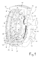
図1は、軸Aの回りに回転可能でかつ内部に通気口を有するブレーキ・ディスク12を備えるディスク・ブレーキ10を三次元的に示す図である。
【0026】
第1キャリア・リング14は、ブレーキ・ディスク12から軸方向に特定距離だけ離れて前記ディスクと平行にかつ軸Aと同軸に配置されている。この第1キャリア・リング14のブレーキ・ディスク12に面する側に複数の摩擦要素16が取り付けられている。摩擦要素16は、以下に詳述するように、ブレーキ・ディスク12をブレーキ作動するのに必要な摩擦力を発生させるために、ブレーキ・ディスク12に対して押しつけられる。第1キャリア・リング14の反対側、すなわち、ブレーキ・ディスク12と面しない側に、一連のウェッジ18が固着されている。各ウェッジ18には、傾斜角αを有する第1面20と傾斜角βを有する第2面22が形成されている。第1キャリア・リング14を平面から見ると、両面20、22は、互いに直接隣接して、基本的に第1キャリア・リング14の周方向に延長している。変更例(図示せず)として、2つの面20、22は図1に例示されるように互いに共通端24において当接せず、その代わりに、それらの面20、22間にキャリア・リング14と平行に延出する部分を有している。
【0027】
図1から明らかなように、2つの面20、22は互いに逆方向に傾き、第2面22の傾斜角βは第1面20の傾斜角αよりも著しく大きい。ウェッジ18は、より明瞭にするために、そのいくつかのみしか図1に示されていないが、キャリア・リング14の周方向から見て、互いに直接的に繋がっている。従って、第1キャリア・リング14の軸方向の全外面はウェッジ18によって覆われている。しかし、他の実施の形態として(図示せず)、第1キャリア・リング14の周方向において、2つの連続するウェッジ18間にある距離を設けてもよい。この場合、キャリア・リング14の軸方向の全外面はウェッジ18によって覆われていないが、その代わり、ウェッジ18は、例えば、グループ化されて配置され、第1キャリア・リング14の周方向において互いに続いている2つのウェッジのグループの間に比較的大きな距離が設けられるとよい。ウェッジ18は第1キャリア・リング14と一体化されてもよいし、別体として作製されてからキャリアリング14に固着されてもよい。
【0028】
第1キャリア・リング14の軸方向外側に、略U字形断面の環状ボルト・キャリア26が配置されている。環状ボルト・キャリア26は、キャリア・リング14に向かって開口される環状空洞28を有し、その環状空洞28内にウェッジ18が突出している。ウェッジ18と同じ数のボルト30(図1には、二個のみが例示されている)がこの環状空洞28内に回転可能に取り付けられている。ウェッジ18と相互作用するように設けられたボルト30の回転軸は軸Aに対して直交している。図1に例示される好適な実施の形態において、各ボルト30は、ボルト・キャリア26に固定された軸に回転可能に取り付けられたスリーブとして具体化されている。
【0029】
電動モータ32は、ボルト・キャリア26の半径方向内側の周面に締結されている。この電動モータ32は、ディスク・ブレーキ10に作動力を付与する電気アクチュエータとして機能し、第1キャリア・リング14の半径方向内側の周面に形成された歯部36と係合する出力ピニオン34を有している。必要に応じて、ギア機構(図示せず)が電動モータ32と出力ピニオン34間に配置されてもよい。
【0030】
ブレーキ・ディスク12の第1キャリア・リング14と対向する側に、第2キャリア・リング38がブレーキ・ディスク12から軸方向にある距離だけ離れてそのブレーキ・ディスク12と平行にかつ軸Aと同軸に配置されている。この第2キャリア・リング38には、ブレーキ・ディスク12に面する側に摩擦要素16’が設けられている。これらの要素は少なくとも本質的に摩擦要素16と対応する点において第2キャリア・リング38に設けられ、ブレーキ操作中にブレーキ・ディスク12に対して押し付けられる。
【0031】
ディスク・ブレーキ10の半径方向外側の領域に、複数のサドル40(図1には三個のサドルが例示されている)が配置されている。これらのサドル40は、ボルト・キャリア26、第1キャリア・リング14、ブレーキ・ディスク12および第2キャリア・リング38と係合し、半径方向内側に突出するアーム42によって、ボルト・キャリア26の軸方向外側の端面および第2キャリア・リング38またはそれに接続される構成要素の軸方向外側の端面に支持される。
【0032】
例示されるディスク・ブレーキ10の機能について説明する。ここで、ディスク・ブレーキ12は矢印ωの方向に回転すると仮定する。この回転方向は、車両に搭載されるディスク・ブレーキ10の前方に向かう走行に相当する。ブレーキ操作を始動するために、電動モータ32が通電され、続いて、第1キャリア・リング14が固着されているボルト・キャリア26対して回転方向ωにおいて角度ψだけ回転するように、出力ピニオン34を駆動する。その結果、ウェッジ18の第1面20が対応するボルト30を押し上げるように当接し、第1キャリア・リング14がブレーキ・ディスク12に対して軸方向に変位され、摩擦要素16がブレーキ・ディスク12に対して押しつけられる。キャリア・リング14の軸方向変位の量sは、式 s=ψ/(2π・P)によって決定される。但し、ψは回転角で、Pは傾斜角αから得られる第1面20の傾斜である。
【0033】
摩擦要素16がブレーキ・ディスク12に押しつけられると、その結果としての反力が生じて、摩擦要素16、第1キャリア・リング14、ボルト・キャリア26およびサドル40を介して、ブレーキ・ディスク12に対する第2キャリア・リング38の軸方向変位をもたらす。その結果、摩擦要素16’が(浮動キャリパの原理で)事実上遅れを生じることなくブレーキ・ディスク12に押しつけられる。
【0034】
ボルト30と相互反応するウェッジ18は自己増力装置を構成する。すなわち、出力ピニオン34を介して電動モータ32によってディスク・ブレーキ10に加えられる作動力は外部からさらに力が加わることなく自動的に増力される。自己増力効果を、図2に概略的に示されたウェッジ18に作用する力の平衡状態に基づいて説明する。図2において、
Finは、ウェッジ18に加えられる入力であり、
FB は、ブレーキ操作中に、ボルト30によって反力となる支持力であり、入力Finと逆方向の力FByとブレーキ・ディスクと直交する圧縮力FBxに分解され、
FN は、力FBxと逆方向の、ブレーキ・ディスクと直交する力であり、
FR は、ウェッジまたは摩擦要素に生じる摩擦力である。
【0035】
この力の平衡によって、ブレーキ・ディスクにおける摩擦力または摩擦トルクFR は、
Fin = −FR ・〔1−tanα/μ〕
の式から明らかなように、傾斜角α、干渉変数である摩擦係数μ、および入力Finにのみ依存する。
【0036】
摩擦係数μは、ブレーキの負荷が大きくなると、比較的大きく変化することがある。ブレーキ操作中に、摩擦係数がこのように変化すると、摩擦力FR が変化し、その結果、ブレーキ作動されるブレーキの構成要素、すなわち、ブレーキ・ディスク12のブレーキ作動による減速状態が変化する。摩擦係数のこのような好ましくない変化を補償するために、例示されたディスク・ブレーキ10は摩擦力を連続的に測定することが可能なセンサ・システム(図示せず)を設けている。この公知のセンサ・システムは、電子制御ユニット(図示せず)に接続されている。電子制御ユニットはセンサ・システムからの受信信号を評価し、詳細には、摩擦力の実値を摩擦力の所定の設定値と比較する。この信号の評価に基づいて、第1キャリア・リング14を回転方向ωまたはその逆方向に回転させることによって、摩擦力の実値を増減させてその実値を設定値と近似させるように、電動モータ32が制御ユニットによって駆動される。
【0037】
システムが良好な制御能力を有するには、特にブレーキ操作の始動時や、ブレーキ負荷が高くブレーキ・ディスク12および摩擦要素16、16’が熱くなるいわゆるフェイディング・モードにブレーキの状態が変化するときに、電動モータ32とウェッジ18間に負荷変動が生じないように、ウェッジ18の第1面20の傾斜Pが選択されることが重要である。
【0038】
負荷変動の抑制は、ブレーキ操作の全範囲にわたって張力のみかまたは圧縮力のみが入力Finとしてモータ32とキャリア・リング14間に加えられるように傾斜角αが選択されること、すなわち、ブレーキ操作の全範囲にわたって入力Finが正または負のいずれかを保つことによって実現される。実際、ある特定の傾斜角αにおいて、入力Finは摩擦係数μの変化によってその正負が変化する可能性がある。その入力Finの正負の変化は駆動列内に存在する遊びの移動範囲において駆動列に好ましくない移動をもたらし、その結果、制御するのが困難な力が飛び跳ねるように生じる。
【0039】
駆動列内の負荷変動を防ぐには、ブレーキ操作の全範囲にわたって、以下の式が満足されることが必要である。
1−tanα/μ<0
この式は、入力Finがブレーキ操作の全範囲にわたって正であることを示し、このような構成のウェッジ装置を圧縮力の加えられるウェッジ装置と呼ぶ。または、駆動列内の負荷変動を防ぐには、ブレーキ操作の全範囲にわたって、以下の式が満足されることが必要である。
1−tanα/μ>0
この式は、入力Finがブレーキ操作の全範囲にわたって負であることを示し、このような構成のウェッジ装置を張力の加えられるウェッジ装置と呼ぶ。
【0040】
もし、入力Finが常に負(張力の加えられるウェッジ装置、FBy<FR )となるように、傾斜角αが選択されるなら、以下の結果が得られる。
【0041】
1.摩擦要素の摩擦係数μは標準的であり、電動モータ32によって加えられる入力Finは比較的高く、その結果、通常のブレーキ操作中において電動モータ32に必要なエネルギーはかなり高い。にも関わらず、電動モータ32に必要なエネルギーは、従来の電気機械式ブレーキと比較して80%以上まで軽減される。
【0042】
2.フェイディングモードにおいて、すなわち、摩擦係数μが低下しているとき、電動モータ32によって加えられる張力は前述の関係に基づいて減少し、従って、必要な摩擦力FR を発生するためのエンジンパワーおよびエンジントルクはほとんど必要とされない。従来の装置と比較して、電動モータ32に必要なエネルギーは、選択される傾斜角αに依存して、95%以上まで軽減される。
【0043】
張力に加えられるウェッジ装置の利点は、増力効果が小さいのでシステムの挙動がより安定し、通常なブレーキ操作中のブレーキの制御能力が改善される点にある。ただし、この利点は、ブレーキが通常に作動しているときはいくらか高いエネルギーが必要である、という犠牲を伴う。
【0044】
一方、入力Finが常に正(圧縮力に加えられるウェッジ装置、FBy>FR )となるように、傾斜角αが選択されるなら、以下の結果が得られる。
【0045】
1.摩擦要素の摩擦係数μは標準的であり、電動モータ32によって加えられる圧縮力Finは理論的には望み通りの低い値に設定可能である。ただし、実際には、制御能力(過度に高い増力効果、干渉変数の影響など)に依存して、過度に小さい圧縮力を選択することはできない。にも関わらず、通常のブレーキ操作において、電動モータ32に必要なエネルギーは、従来の自己増力装置を有しない電気機械式ブレーキと比較して90、95%、それ以上まで軽減される。
【0046】
2.フェーディングモードにおいて、電動モータ32によって加えられる圧縮力は増し、従って、必要な摩擦力FR を発生するためのエンジンパワーおよびエンジントルクは大きくなる。
【0047】
圧縮力の加えられるウェッジ装置の利点は、フェイディングモードにおいて比較的高い力を加えるように設計された電動モータ32が、通常なブレーキ操作中ではトルクと力にかなりの余裕があるので、通常のブレーキ操作中に良好な動的性能を発揮することができる点にある。
【0048】
例示されたディスク・ブレーキ10による前記のブレーキ操作の説明において、圧縮力が加えられるウェッジ装置が基本的には用いられた。すなわち、ウェッジ18は第1キャリア・リング14の対応する回転に基づいてボルト30を加圧する。一方、張力が加えられるウェッジ装置においては、対応する傾斜角αの選択によって予め定めることによって、電動モータ32は反対方向に回転する。駆動列にプレストレスを与える張力の加えられるウェッジ装置は図1に例示されていない。
【0049】
始動されたブレーキ操作を終了させるために、電動モータ32は、出力ピニオン34が作動中に移動したのと反対方向に回転し、その結果、第1キャリア・リング14は始動位置に再び復帰し、すなわち、ウェッジ18の第1面20がボルト30から離れ、キャリア・リング14はブレーキ・ディスク12から軸方向において離れるように移動する。
【0050】
また、逆方向に走行する車両もウェッジ18の傾斜角βを有する第2面22を用いてブレーキ作動される。この第2面22の傾斜角βは、逆方向の走行のブレーキ操作には通常特に大きな摩擦力が必要とされないので、第1面20の傾斜角αよりも著しく大きく選択される。傾斜角αよりも傾斜角βが大きいので、逆方向に走行する場合のブレーキ操作において、電動モータ32は大きいエネルギーが必要であるが、これは逆方向に走行する場合のブレーキ操作は通常低いブレーキ力しか必要としないので不都合とはならない。
【0051】
もしブレーキ・ディスク12が矢印ωと逆方向に回転すると(車両が逆方向に走行すると)、例えば、現在通常に用いられているABSシステムのセンサーシステムによって、回転方向の変化が検出されるので、第2面22がボルト30を押し上げるように当接するまで第1キャリア・リング14が電動モータ32によって回転される。以後のブレーキ操作は前述の通りである。
【0052】
変更例として、逆方向に走行する場合のブレーキ操作を第1面20によって行うことも可能である。ただし、そのために、電動モータ32は(特に圧縮力が加えられるウェッジ装置の場合、すなわち、傾斜角αが大きい場合)十分な力および/またはトルクを必要とする。なぜなら、ウェッジ18とボルト30の組み合わせは非自己増力装置として作用するので、電動モータ22は必要な摩擦力を完全に付与しなければならないからである。
【0053】
実施の形態において詳細に述べられたブレーキはディスク・ブレーキとして実施されているが、ドラム・ブレーキとして実施することも可能である。その場合、ウェッジ18は、例えば、ドラムブレーキのシューの半径方向内側に配置されるとよい。さらに、自己増力効果は、ウェッジ以外に、例えば、4本の連鎖バーのの形態によっても達成される。
【0054】
【発明の効果】
上記のように、本発明によれば、ブレーキ作動される構成要素と電気アクチュータ間に電気アクチュエータによって生じる作動力の自己増力をもたらす装置を設け、さらに摩擦力の設定値と摩擦力の実値を比較する装置を設け、摩擦力の実値が設定値から偏った場合に、それに対応して、電気アクチュエータを駆動してその作動力を増減させて摩擦力の実値を設定値に近似させるように構成したので、電気アクチュエータによって加える作動力を容易に、例えば、従来の値の略2%にまで軽減することができ、その結果、著しく小さく従ってより軽量で安価な、かつ付加的に動的性能の改善された電動モータをアクチュエータとして用いることが可能である。
【図面の簡単な説明】
【図1】本発明によるディスク・ブレーキとして構成された電気機械式ブレーキを三次元的に示す図である。
【図2】図1に例示されたブレーキのウェッジに作用する各力を表す図表である。
【符号の説明】
10 ディスク・ブレーキ
12 ブレーキ・ディスク
14 第1キャリア・リング
16,16’ 摩擦要素
18 ウェッジ
20 第1面
22 第2面
24 共通端
26 環状ボルト・キャリア
28 環状空洞28
30 ボルト
32 電動モータ
34 出力ピニオン
36 歯部
38 第2キャリア・リング
40 サドル
42 アーム
α、β 傾斜角[0001]
BACKGROUND OF THE INVENTION
The present invention provides an actuating force to generate an actuating force and pressurize the friction element against at least one friction element in order to provide a frictional force to a rotatable component of the brake to be braked. The invention relates to an electromechanical brake, in particular for a vehicle, having an applied electric actuator.
[0002]
[Prior art]
Electromechanical brakes are well known per se. DE 195 43 098 C2 (German Patent Specification) describes an electrically operable vehicle brake designed as a disc brake. The brake lining of this vehicle brake is pressed against the brake disc by an electric motor. The electric motor transmits its operating force via a so-called planetary rolling contact threaded spindle to an axially displaceable piston interacting with the brake lining.
[0003]
WO 96/03301 (International Publication Number) describes yet another electrically operable vehicle brake designed as a disc brake. The brake lining of the vehicle brake is pressed against the brake disc by an electric motor that functions as an actuator. This electric motor is provided with a spindle gear mechanism and is connected to an axially displaceable piston acting on the brake lining in the direction of displacement of the brake lining by means of spindle elements of different designs. In this patent document, a gear mechanism for converting torque and rotational speed is optionally provided.
[0004]
[Problems to be solved by the invention]
The main problem with conventional brakes with electric actuators is that the actuators must apply a high actuation force in order to achieve a sufficient braking effect. In order to apply this high actuating force, the actuator requires a large amount of power, and it is necessary to use a very large drive unit, usually an expensive electric motor having a large torque and a large weight as a drive source. As a result, electromechanical brakes have not been widely used to date, for example as vehicle brakes.
[0005]
It is an object of the present invention to provide an electromechanical brake suitable for, for example, a motor vehicle or a track vehicle, having an electric actuator that only needs to apply an actuation force much smaller than that of a conventional brake of the same type. . The present invention further aims to provide an electromechanical brake in which a very good control response and high dynamic performance are particularly important.
[0006]
[Means for Solving the Problems]
To achieve the above object, an electromechanical brake of the present invention of the type described at the outset provides a device for providing a self-intensification of the actuating force generated by the electric actuator between the brake actuated component and the electric actuator. Further, a device for comparing the set value of the frictional force with the actual value of the frictional force is provided, and the device for comparing the frictional force corresponds to the case where the actual value of the frictional force deviates from the set value. The actuator is driven to increase or decrease its operating force to approximate the actual value of the frictional force to a set value.
[0007]
Electric actuator for the force required to produce a predetermined friction force in a self-energizing device used in the present invention to increase the actuating force generated by the electric actuator in a purely mechanical manner without introducing auxiliary force Although the ratio of the actuating force due to is 100% in the conventional electromechanical brake, it is greatly reduced. According to the present invention, the largest part of the force required to produce a predetermined friction force is applied by the self-energizing device. Therefore, the operating force applied by the actuator during normal braking operation can be easily reduced, for example, to about 2% of the conventional value. The power required for the brake of the present invention is also reduced to some extent. As a result, an electric motor that is significantly smaller and therefore lighter and cheaper and additionally has improved dynamic performance can be used as an actuator.
[0008]
So-called self-intensifying brakes are conventionally known, especially in the field of drum brakes for motor vehicles. However, the self-intensifying brake has the disadvantage that the coefficient of friction increases disproportionately as the operating force increases. In conventional hydraulic brake systems, the distribution of braking force in individual wheel brakes and cylinders is determined by the brake line pressure and the hydraulic piston area, so when self-intensifying braking is used, the friction lining and braking of the brake Due to the different coefficients of friction that actually exist between the brake discs or brake drums that are applied, the phenomenon that the friction forces at the individual wheels of the vehicle are very different is inevitable. The driver of the vehicle can also recognize the phenomenon that the frictional force is different for each wheel. This is because such a phenomenon causes the vehicle to lean during braking, that is, the vehicle unintentionally changes the direction of travel. In particular, when a brake operation is performed on a slippery road surface, a side slip may occur due to such a phenomenon that the frictional force is different for each wheel. Due to the disadvantages associated with the phenomenon of different frictional forces, self-intensifying brakes have not been used as useful brakes in the field of motor vehicles for quite some time.
[0009]
The present invention overcomes this long-standing prejudice in this field of expertise and is relatively complex consisting of multiple elements consisting of an engine and downstream power transmission elements (including associated bearings and gear mechanisms). To drive a simple drive train, the fact that electromechanical brakes usually have a sensor system that measures the force or torque and / or position to generate a predetermined distribution of braking force Yes. According to the present invention, such a known sensor system is used without any change in order to perform a comparison between the set value and the actual value relating to the frictional force described above, whereby the set value and the actual value are used. When the difference is detected, the electric actuator is driven so that the actual value of the frictional force approximates the set value, for example, by an electronic control unit connected to the sensor system. In the present specification, the actual value of the frictional force is measured directly or indirectly by a known method.
[0010]
Due to the greatly reduced actuating force due to the actuator, the electromechanical brake according to the invention has a significantly improved dynamic performance compared to the conventional electromechanical brake, so that the electromechanical brake according to the invention The aforementioned associated with the self-energizing device, since fluctuations in the frictional force between the frictional element and the braked component are compensated for the speed, for example it will not adversely affect the driving performance of the motor vehicle. It is possible to take advantage of its advantages by eliminating the disadvantages.
[0011]
According to a preferred embodiment of the electromechanical brake according to the invention, the self-energizing device comprises at least one wedge which is slidably or rollably supported on the associated abutment with an inclination angle α. Have. According to one embodiment, the input applied to the self-energizing device by the electrical actuator is the normal direction of rotation of the braked component, regardless of the change in the coefficient of friction between the friction element and the braked component. Is defined to be always positive with respect to. A wedge having an inclination angle α at which such input is positive is also called a pressure wedge. This is because the size of the self-energizing device depends only on the selection of the inclination angle α, and when the inclination angle α with positive input is selected as described above, the entire braking force is independent of the change in the friction coefficient μ. This is because the size is determined so that a predetermined frictional force is obtained by applying a compressive force to the wedge in the operating state. Here, the compressive force is applied by an electric actuator. By using such a wedge device to which a compressive force is applied, the energy required for the electromechanical brake according to the invention depends on the design, i.e. the choice of the inclination angle α, and has a self-energizing device in normal operation. It can be reduced to 2% of the energy required for conventional electromechanical brakes, and to about 17% in fading mode.
[0012]
Here, the term fading operation means an operating state of a brake in which a temperature change is caused by an extremely strong braking force and gas is released from the brake lining, thereby reducing a coefficient of friction. Brake fading occurs in motor vehicles, especially after repeated braking operations from high speeds or when traveling on relatively long downhills in mountainous areas.
[0013]
According to another embodiment of the electromechanical brake according to the present invention, the input applied to the self-boosting device by the electric actuator is applied to the brake regardless of the change in the coefficient of friction between the friction element and the braked component. The tilt angle α is determined so that it is always negative with respect to the normal direction of rotation of the components to be driven, and pre-stressed in the negative input direction in this embodiment for all drive trains between the electric actuator and the self-energizing device. Is added. Contrary to the wedge device to which the compressive force is applied, when this negative input is continuously added, it is called a wedge device to which tension is applied, and tension is applied to the wedge in each operation state of the brake. . The wedge device to which this tension is applied can be obtained by appropriately selecting an inclination angle α smaller than the inclination angle of the wedge device to which the compressive force is applied. The advantage of a wedge device to which tension is applied is that the boosting effect is low when the tension is applied, so that the brake behaves more stably and, as a result, improves the controllability of the brake during normal braking operation. There is a point that can be. However, this advantage is achieved at the cost of significantly higher energy required during normal braking operation compared to a wedge device to which a compressive force is applied.
[0014]
In the fading mode, a tensioned wedge device has its frictional coefficient μ decreased, so that the applied tension is drastically reduced. In this state, the actuator generates an operating force to generate the necessary frictional force. Almost no need.
[0015]
The wedge device to which the compressive force is applied and the wedge device to which the tension is applied are such that the possibility of load fluctuations that can occur in the drive train is eliminated in the entire operation range of the brake. However, in order to avoid any load fluctuations in the drive train, in the case of a wedge device to which tension is applied, it is necessary to additionally apply prestress to the drive train, as already described.
[0016]
In a preferred embodiment according to the invention, the braked component is a brake disc and the self-energizing device is a carrier ring which is arranged in parallel and coaxial with the brake disc in a gap. The carrier ring is provided with a series of wedges on the side opposite the side facing the brake disc. The wedges each have a first surface supported by a bolt that is rotatably mounted with an inclination angle α.
[0017]
According to one embodiment of this brake, all bolts are provided in an annular bolt carrier that is arranged coaxially with the carrier ring, and the rotational axis of all bolts is relative to the rotational axis of the brake disc. Arranged at right angles, the carrier ring and bolt carrier are rotatable relative to each other about the axis of rotation of the brake disc. The relative rotation of the bolt carrier and carrier ring allows the wedge and bolt to run relative to each other and the gap between the carrier ring and bolt carrier is a function of the relative rotation and tilt angle α. Increase as.
[0018]
The aforementioned carrier ring is preferably designed as an internal tooth having teeth on the inner periphery. The electric actuator and the internal tooth are preferably connected by an output pinion that engages with the tooth portion described above and can be driven by the electric actuator.
[0019]
In a preferred embodiment of such a brake designed as a disc brake according to the invention, the annular bolt carrier is fixed and the carrier ring designed as an internal tooth is connected to the axis of rotation of the brake disc by means of an electric actuator. Around the bolt carrier. However, as a modification, the carrier ring may be designed to be fixed and the bolt carrier to be rotated.
[0020]
In a brake according to the invention with a carrier ring, it is preferred that a plurality of friction elements are arranged on the side of the carrier ring facing the brake disc. These friction elements are axially pressed against the brake disc by a wedge present on the other side of the carrier ring. In consideration of the thermal influence, the plurality of friction elements are preferably arranged apart from each other in the circumferential direction of the carrier ring. However, if a relatively large friction lining surface is required, it is possible to arrange a single continuous annular friction element. The friction element may be directly connected to the carrier ring, for example by gluing, or it may be attached to the carrier ring in a manner that can be easily detached by attaching it to a separate carrier plate.
[0021]
The height of each wedge provided on the carrier ring has a maximum load applied to at least a predetermined adjustment amount of the disc brake, that is, a maximum allowable wear amount of the friction element in a direction orthogonal to the carrier ring. In this case, it is preferable to correspond to the sum of the deformation amount of the brake component supporting the friction element. This adjustment movement amount is given only by the wedge device.
[0022]
In a preferred embodiment of the brake according to the invention with a carrier ring, each wedge is arranged adjacent immediately after the preceding wedge in the circumferential direction of the carrier ring. Thus, play in the movement of the wedge is minimized. Moreover, it is preferable that each wedge is provided with the 2nd surface supported by the volt | bolt attached rotatably. The second surface is preferably inclined in the opposite direction to the first surface and has an inclination angle β larger than the inclination angle α. In such a self-energizing device, the first surface having the inclination angle α is used when the vehicle travels forward, and the second surface inclined at the inclination angle β is used for braking operation on the vehicle traveling in the reverse direction. Used. By making the inclination angle of the second surface larger than the inclination angle α, the overall length of each wedge can be shortened to save space. Even when the inclination angle of the second surface is increased, the braking force required for the braking operation when traveling in the reverse direction is usually significantly higher than the braking force required for the braking operation when traveling forward. It is not inconvenient because it is small.
[0023]
In the preferred embodiment of the brake according to the invention, an electric motor is used as the electric actuator, but other drive units can also be used.
[0024]
DETAILED DESCRIPTION OF THE INVENTION
In the following, a preferred embodiment of an electromechanical brake constructed as a disc brake according to the present invention will be described in detail with reference to the accompanying schematic drawings.
[0025]
FIG. 1 is a three-dimensional view of a
[0026]
The first carrier ring 14 is disposed at a specific distance in the axial direction from the
[0027]
As is apparent from FIG. 1, the two
[0028]
An
[0029]
The
[0030]
On the side of the
[0031]
A plurality of saddles 40 (three saddles are illustrated in FIG. 1) are disposed in a radially outer region of the
[0032]
The function of the exemplified
[0033]
When the
[0034]
The wedge 18 that interacts with the
F in Is the input applied to wedge 18,
F B Is a supporting force that is a reaction force by the
F N Is the force F Bx It is the force that is perpendicular to the brake disc in the opposite direction,
F R Is the friction force generated in the wedge or friction element.
[0035]
This balance of forces causes the frictional force or frictional torque F on the brake disc. R Is
F in = -F R ・ [1-tan α / μ]
As is clear from the equation, the inclination angle α, the friction coefficient μ that is an interference variable, and the input F in Depends only on.
[0036]
The friction coefficient μ may change relatively greatly as the brake load increases. When the friction coefficient changes in this way during the braking operation, the friction force F R As a result, the components of the brake to be braked, that is, the deceleration state due to the brake operation of the
[0037]
In order for the system to have good control capability, especially when the brake operation starts, or when the brake state changes to a so-called fading mode in which the brake load is high and the
[0038]
The load fluctuation can be suppressed by inputting only the tension or the compression force over the entire range of the brake operation. in Is selected so that it is applied between the
[0039]
In order to prevent load fluctuations in the drive train, the following equation must be satisfied over the entire range of braking operations.
1-tan α / μ <0
This equation is input F in Is positive over the entire range of braking operation, and a wedge device having such a configuration is called a wedge device to which a compressive force is applied. Alternatively, in order to prevent load fluctuations in the drive train, it is necessary that the following equation is satisfied over the entire range of brake operation.
1-tan α / μ> 0
This equation is input F in Is negative over the entire range of braking operation, and a wedge device with such a configuration is referred to as a tensioned wedge device.
[0040]
If input F in Is always negative (wedge device to which tension is applied, F By <F R If the tilt angle α is chosen so that:
[0041]
1. The friction coefficient μ of the friction element is standard and the input F applied by the
[0042]
2. In fading mode, i.e. when the coefficient of friction [mu] is decreasing, the tension applied by the
[0043]
The advantage of the wedge device in addition to the tension is that the boosting effect is small so that the behavior of the system is more stable and the controllability of the brake during normal braking operation is improved. However, this advantage comes at the cost of requiring somewhat higher energy when the brake is operating normally.
[0044]
On the other hand, input F in Is always positive (wedge device applied to compressive force, F By > F R If the tilt angle α is chosen so that:
[0045]
1. The friction coefficient μ of the friction element is standard, and the compression force F applied by the
[0046]
2. In the fading mode, the compressive force applied by the
[0047]
The advantage of a wedge device to which a compressive force is applied is that the
[0048]
In the description of the above brake operation by the illustrated
[0049]
In order to finish the started brake operation, the
[0050]
A vehicle traveling in the opposite direction is also braked using the
[0051]
If the
[0052]
As an example of a change, it is also possible to perform the brake operation when traveling in the reverse direction using the first surface 20. However, for that purpose, the
[0053]
The brake described in detail in the embodiment is implemented as a disc brake, but can also be implemented as a drum brake. In that case, the wedge 18 is good to be arrange | positioned at the radial inside of the shoe of a drum brake, for example. Furthermore, the self-boosting effect is achieved not only by the wedge but also by the form of, for example, four chain bars.
[0054]
【The invention's effect】
As described above, according to the present invention, a device for providing a self-intensification of the actuation force generated by the electric actuator is provided between the brake actuated component and the electric actuator, and the frictional force set value and the actual frictional force value A device for comparison is provided, and when the actual value of the frictional force deviates from the set value, correspondingly, the electric actuator is driven to increase or decrease the operating force to approximate the actual value of the frictional force to the set value. As a result, the actuating force applied by the electric actuator can be easily reduced, for example, to about 2% of the conventional value, so that it is significantly smaller and thus lighter, cheaper and additionally dynamic. It is possible to use an electric motor with improved performance as an actuator.
[Brief description of the drawings]
FIG. 1 is a three-dimensional view of an electromechanical brake configured as a disc brake according to the present invention.
FIG. 2 is a chart showing each force acting on a wedge of the brake illustrated in FIG. 1;
[Explanation of symbols]
10 Disc brake
12 Brake disc
14 First carrier ring
16, 16 'friction element
18 wedges
20 First side
22nd side
24 Common end
26 Annular bolt carrier
28
30 volts
32 Electric motor
34 output pinion
36 teeth
38 Second Carrier Ring
40 saddles
42 arms
α, β tilt angle
Claims (13)
Applications Claiming Priority (2)
| Application Number | Priority Date | Filing Date | Title |
|---|---|---|---|
| DE19819564A DE19819564C2 (en) | 1998-04-30 | 1998-04-30 | Self-energizing electromechanical brake |
| DE198195648 | 1998-04-30 |
Publications (2)
| Publication Number | Publication Date |
|---|---|
| JPH11315865A JPH11315865A (en) | 1999-11-16 |
| JP3902874B2 true JP3902874B2 (en) | 2007-04-11 |
Family
ID=7866433
Family Applications (1)
| Application Number | Title | Priority Date | Filing Date |
|---|---|---|---|
| JP27240398A Expired - Lifetime JP3902874B2 (en) | 1998-04-30 | 1998-09-28 | Electromechanical brake |
Country Status (4)
| Country | Link |
|---|---|
| US (1) | US6318513B1 (en) |
| EP (1) | EP0953785B1 (en) |
| JP (1) | JP3902874B2 (en) |
| DE (2) | DE19819564C2 (en) |
Families Citing this family (115)
| Publication number | Priority date | Publication date | Assignee | Title |
|---|---|---|---|---|
| JP3740005B2 (en) * | 1999-11-01 | 2006-01-25 | トヨタ自動車株式会社 | Braking torque control device |
| DE10005758B4 (en) * | 2000-02-09 | 2011-02-24 | Volkswagen Ag | Method for determining the state of wear of a brake lining and corresponding electromechanical brake arrangement |
| GB0018154D0 (en) | 2000-07-25 | 2000-09-13 | Federal Mogul Brake Systems Li | Apparatus and method for controlling a braking system |
| DE10037055A1 (en) * | 2000-07-29 | 2002-02-14 | Bosch Gmbh Robert | disc brake |
| DE10037599A1 (en) * | 2000-08-02 | 2002-02-21 | Bosch Gmbh Robert | Drum brake device |
| DE10046177A1 (en) * | 2000-09-19 | 2002-04-04 | Bosch Gmbh Robert | disc brake |
| DE10056451A1 (en) * | 2000-11-14 | 2002-05-29 | Bosch Gmbh Robert | disc brake |
| DE10104739C1 (en) * | 2001-02-02 | 2002-11-28 | Bosch Gmbh Robert | Disk brake for a vehicle is released by rotating a friction brake lining that is fixed during operation of the disk brake in the same direction as a friction brake lining that is rotated during operation of the disk brake |
| EP1389282A1 (en) | 2001-05-21 | 2004-02-18 | Estop GmbH | Electromechanical brake with self-boosting and adjustable wedge angle |
| DE10154178B4 (en) | 2001-05-21 | 2004-05-13 | Estop Gmbh | Self-energizing electromechanical brake with variable wedge angle |
| DE10149695B4 (en) * | 2001-10-09 | 2004-01-29 | Estop Gmbh | Electromechanical floating caliper partial brake disc brake with self-reinforcement |
| DE10151950B4 (en) | 2001-10-22 | 2005-04-21 | Estop Gmbh | Self-energizing electromechanical disc brake with friction torque detection |
| DE10164317C1 (en) * | 2001-12-28 | 2003-10-09 | Estop Gmbh | Self-energizing electromechanical partial brake disc brake with improved friction lining guidance |
| DE10201607A1 (en) * | 2002-01-16 | 2003-07-24 | Continental Teves Ag & Co Ohg | Disk brake for motor vehicles has an activating device coupled to a brake lining/pad applying brake application stroke force by means of a self-energizing device. |
| DE10201555A1 (en) * | 2002-01-17 | 2003-08-07 | Bosch Gmbh Robert | Electromechanical friction brake for motor vehicle, has disc brake with wedge shaped backing to apply pad to rotor |
| DE10204947A1 (en) * | 2002-02-07 | 2003-08-21 | Zahnradfabrik Friedrichshafen | Electromagnetically actuated friction clutch or brake |
| AU2003206572A1 (en) * | 2002-02-21 | 2003-09-09 | Haldex Brake Products Ab | A disc brake |
| FR2838694B1 (en) * | 2002-04-18 | 2004-07-09 | Bosch Gmbh Robert | BRAKING DEVICE FOR A MOTOR VEHICLE AND BRAKING SYSTEM COMPRISING SUCH A DEVICE |
| DE10218825B4 (en) * | 2002-04-26 | 2004-04-29 | Estop Gmbh | Motor vehicle brake system with parking brake function and electromechanical brake for such a motor vehicle brake system |
| WO2003091591A1 (en) * | 2002-04-26 | 2003-11-06 | Estop Gmbh | Motor vehicle brake system comprising a parking brake function and electromechanical wheel brake for such a motor vehicle brake system |
| US6752247B2 (en) * | 2002-05-06 | 2004-06-22 | Ford Global Technologies, Llc | Method and an assembly for braking a selectively moveable assembly having a controllably varying amount of self energization |
| DE10223389A1 (en) * | 2002-05-25 | 2003-12-04 | Continental Teves Ag & Co Ohg | friction brake |
| US7748793B2 (en) | 2002-05-28 | 2010-07-06 | Estop Gmbh | Fail-safe concept for an electromechanical brake |
| DE50313257D1 (en) * | 2002-05-28 | 2010-12-23 | Estop Gmbh | ERROR SAFETY CONCEPT FOR A SELF-REINFORCED ELECTROMECHANICAL BRAKE |
| DE10226035A1 (en) * | 2002-06-12 | 2003-12-24 | Bosch Gmbh Robert | Brake, especially disc brake |
| DE10229455B4 (en) * | 2002-07-01 | 2005-04-21 | Estop Gmbh | Single-track vehicle with electromechanical disc brake |
| US6932198B2 (en) * | 2002-08-07 | 2005-08-23 | Ford Global Technologies, Llc | Brake assembly and a method for braking a vehicle or another selectively movable assembly |
| DE10255192B4 (en) * | 2002-11-27 | 2015-03-19 | Robert Bosch Gmbh | Electromechanical brake |
| DE10261455B8 (en) * | 2002-12-31 | 2019-05-29 | Robert Bosch Gmbh | Friction brake with self-reinforcement |
| DE10302516A1 (en) * | 2003-01-23 | 2004-08-05 | Robert Bosch Gmbh | Disc brake with mechanical self-reinforcement |
| DE10319082B3 (en) * | 2003-04-28 | 2004-12-16 | Estop Gmbh | Electromechanical brake for rotary components has actuator arrangement with separately controllable actuators, each associated with frictional element moved along wedge surface to press on braked part |
| US7293842B2 (en) * | 2003-07-02 | 2007-11-13 | Haldex Brake Products Ltd. | Control network for vehicle dynamics and ride control systems having distributed electronic control units |
| US6959968B2 (en) * | 2003-07-02 | 2005-11-01 | Haldex Brake Products Ltd. | Central electronic control network for vehicle dynamics and ride control systems in heavy vehicles |
| DE10335402A1 (en) | 2003-08-01 | 2005-02-17 | Robert Bosch Gmbh | Electromechanical friction brake with self-reinforcement |
| US6899202B1 (en) | 2003-08-13 | 2005-05-31 | Mcintyre John | Brake assembly for a bicycle |
| DE10338449A1 (en) * | 2003-08-21 | 2005-03-17 | Robert Bosch Gmbh | Vehicle braking system with self-boosting electromechanical wheel brakes has self- boosting only effective in forward direction of travel for front axle brakes, in reversing, forward, both or no directions for rear axle brakes |
| DE10342013A1 (en) * | 2003-09-11 | 2005-05-04 | Estop Gmbh | Friction clutch esp. for vehicle, has electromechanical actuation arrangement provided with self-amplifying device |
| US7314257B2 (en) | 2003-09-26 | 2008-01-01 | Haldex Brake Products Ab | Tire slip model |
| SE0302563D0 (en) * | 2003-09-26 | 2003-09-26 | Haldex Brake Prod Ab | A parking brake mechanism for a disc brake |
| US20050071070A1 (en) * | 2003-09-26 | 2005-03-31 | Peter Nilsson | Brake system with distributed electronic control units responsive to sensor input |
| US7347304B2 (en) | 2003-09-26 | 2008-03-25 | Haldex Brake Products Ab | System for control of brake actuator |
| US6991302B2 (en) * | 2003-09-26 | 2006-01-31 | Haldex Brake Products Ab | Brake system with distributed electronic control units |
| US7448701B2 (en) | 2003-09-26 | 2008-11-11 | Haldex Brake Products Ab | System for control of brake actuator based at least in part upon tire/road friction force |
| US7497526B2 (en) * | 2003-09-26 | 2009-03-03 | Haldex Brake Products Ab | Brake system with distributed electronic control units |
| US7096108B2 (en) * | 2003-09-26 | 2006-08-22 | Haldex Brake Products Ab | Brake system with distributed electronic control units incorporating failsafe mode |
| US6984001B2 (en) * | 2003-09-29 | 2006-01-10 | Haldex Brake Products Ab | Power supply network for brake system |
| US7359786B2 (en) * | 2003-09-29 | 2008-04-15 | Haldex Brake Products Ab | Control and power supply network for vehicle braking system |
| US7396088B2 (en) * | 2003-09-29 | 2008-07-08 | Haldex Brake Products Ab | Power supply network for brake system |
| US7150506B2 (en) * | 2003-09-29 | 2006-12-19 | Haldex Brake Products Ab | Control network for brake system |
| DE10347792A1 (en) * | 2003-10-14 | 2005-05-12 | Bosch Gmbh Robert | wheel brake |
| DE10347942A1 (en) * | 2003-10-15 | 2005-05-19 | Robert Bosch Gmbh | Self-power boost type electromechanical disk brake for vehicles, has floating caliper equipped with tie rod connected to brake-lining holders which are slid selectively along tie rod to change space between brake-lining holders |
| DE10356936A1 (en) * | 2003-12-05 | 2005-06-30 | Robert Bosch Gmbh | Self-reinforcing electromechanical vehicle brake |
| DE10361265A1 (en) * | 2003-12-24 | 2005-07-28 | Robert Bosch Gmbh | Self-energizing electromechanical friction brake |
| US7055658B2 (en) * | 2003-12-29 | 2006-06-06 | Arvinmeritor Technology, Llc | Gain stabilizing self-energized brake mechanism |
| US20080078631A1 (en) * | 2004-02-05 | 2008-04-03 | Erlston Lester J | Disc brake in combination with brushless electric motor-generator |
| US20060260886A1 (en) * | 2004-02-05 | 2006-11-23 | Erlston Lester J | Coaxial helical brake and method of braking in lightweight brake configuration |
| DE102004008383A1 (en) * | 2004-02-20 | 2005-09-15 | Estop Gmbh | Method for compensating for variation in transmission characteristics of an electronic brake system involves determining operating parameters in two operating conditions and compensating for differences |
| US20050216160A1 (en) * | 2004-03-23 | 2005-09-29 | Delphi Technologies Inc. | Method for detecting electric-mechanical-brake pad drag and/or calculating actuator efficiency |
| DE102004029841A1 (en) * | 2004-06-19 | 2006-01-05 | Robert Bosch Gmbh | Self-energizing electromechanical friction brake |
| CN101065596B (en) * | 2004-10-13 | 2010-09-22 | 克诺尔商用车制动系统有限公司 | Self-energising disk brake and control method for a self-energising brake |
| DE102005030620A1 (en) * | 2004-10-13 | 2006-04-20 | Knorr-Bremse Systeme für Nutzfahrzeuge GmbH | Disc brake in self-boosting design |
| DE102005030618A1 (en) * | 2004-10-13 | 2006-04-20 | Knorr-Bremse Systeme für Nutzfahrzeuge GmbH | Disc brake in self-reinforcing design and control method for a self-energizing brake |
| DE102005030621A1 (en) * | 2004-10-13 | 2006-04-20 | Knorr-Bremse Systeme für Nutzfahrzeuge GmbH | Disc brake in self-reinforcing design and control method for a self-energizing brake |
| DE102005030617A1 (en) * | 2004-10-13 | 2006-04-20 | Knorr-Bremse Systeme für Nutzfahrzeuge GmbH | Disc brake in self-reinforcing design and control method for a self-energizing brake |
| US20060253243A1 (en) * | 2005-05-06 | 2006-11-09 | Jacob Svendenius | System and method for tire/road friction estimation |
| DE102005027916B4 (en) * | 2005-06-16 | 2013-04-11 | Knorr-Bremse Systeme für Nutzfahrzeuge GmbH | Vehicle brake in self-reinforcing design |
| DE102005036827B4 (en) * | 2005-08-04 | 2019-10-31 | Continental Automotive Gmbh | Safety system of a regulated electromechanical vehicle brake equipment |
| DE102005041098A1 (en) * | 2005-08-30 | 2007-03-08 | Siemens Ag | retractor |
| DE102005045114B4 (en) * | 2005-09-21 | 2007-11-29 | Siemens Ag | Electromechanically operated self-energizing brake device |
| DE102005048884B3 (en) * | 2005-10-12 | 2007-05-03 | Siemens Ag | Electromechanical brake with energy storage and downstream power transmission unit |
| DE102005055295B4 (en) * | 2005-11-21 | 2014-02-13 | Continental Automotive Gmbh | Electromechanical brake with backlash-free operation |
| DE102005057544B4 (en) * | 2005-12-01 | 2008-01-10 | Siemens Ag | Method for controlling the current consumption of a self-energizing electromechanical brake |
| DE102006000763B3 (en) * | 2006-01-04 | 2007-04-12 | Siemens Ag | Electromechanical brake for vehicle has stack of elements to maintain stable stress in component being braked |
| DE102006002254B3 (en) * | 2006-01-17 | 2007-07-05 | Siemens Ag | Self-energizing brake e.g. for motor vehicle, has frictional member, which can be pressed by actuator, against friction surface of element to be braked or disengaged |
| US20070199781A1 (en) * | 2006-02-27 | 2007-08-30 | Robert Bosch Corporation | Disc Brake |
| DE102006012440A1 (en) * | 2006-03-17 | 2007-09-20 | Siemens Ag | Brake with spindle and cam arrangement |
| US20070227837A1 (en) * | 2006-03-28 | 2007-10-04 | Akebono Corporation (North America) | Wedge roller ramp parking brake assembly |
| DE102006015032A1 (en) * | 2006-03-31 | 2007-10-11 | Siemens Ag | Frictional coefficient determination method, especially for motor vehicle brakes, involves determining frictional relationship between frictional coefficients and normal force components |
| DE102006015034B4 (en) * | 2006-03-31 | 2010-11-18 | Continental Automotive Gmbh | Method and arithmetic unit for determining a performance parameter of a brake |
| DE102006015741A1 (en) * | 2006-04-04 | 2007-10-11 | Robert Bosch Gmbh | Self-reinforcing electromechanical partial disc brake |
| DE102006024710A1 (en) * | 2006-05-26 | 2007-11-29 | Siemens Ag | Self-energizing brake has emergency release system comprising cam disk with notched edge whose lower rim rests on ball bearings in operating position, but falls so that bearings fit into notches when power is shut off |
| US7630813B2 (en) * | 2006-06-06 | 2009-12-08 | Delphi Technologies, Inc. | Method for controlling electromechanical brakes using parameter identification and no additional sensors |
| DE102006027206A1 (en) * | 2006-06-12 | 2007-12-13 | Siemens Ag | Electromechanical brake for braking e.g. motor vehicle`s wheel, has lock mechanism cooperating with self reinforcement unit such that lock mechanism holds unit in given position, or disconnects unit for replacement of unit |
| DE102006034848A1 (en) * | 2006-07-27 | 2008-01-31 | Siemens Ag | Cord brake i.e. safety belt brake, for motor vehicle, has operating unit standing in active connection with bearing unit such that bearing units are movable relative to each other and brake cords come into frictional contact with brake pad |
| KR101377388B1 (en) * | 2006-08-07 | 2014-03-21 | 콘티넨탈 테베스 아게 운트 코. 오하게 | Method for the operation of an electromechanically operable parking brake |
| DE102006046030A1 (en) * | 2006-09-28 | 2008-04-03 | Siemens Ag | Backlash-free drive for an electromechanical brake device |
| DE102006046029A1 (en) * | 2006-09-28 | 2008-04-03 | Siemens Ag | Asymmmatic braking |
| DE102006051141A1 (en) * | 2006-10-30 | 2008-05-08 | Siemens Ag | Machine tool, production machine and / or handling machine |
| ATE408076T1 (en) * | 2006-11-27 | 2008-09-15 | Haldex Brake Prod Ab | DISC BRAKE AND METHOD FOR DETECTING THE FORCES IN SUCH A DISC BRAKE |
| DE102006058565A1 (en) * | 2006-12-12 | 2008-06-19 | Siemens Ag | Balanced wedge control |
| ITMI20062496A1 (en) * | 2006-12-22 | 2008-06-23 | St Microelectronics Srl | CONTROL SYSTEM FOR BRAKING DEVICES BASED ON A BRAKING TORQUE SENSOR |
| US9732813B2 (en) * | 2006-12-29 | 2017-08-15 | Haldex Brake Products Ab | Park lock and pad wear adjusting arrangement for electrically actuated brake |
| DE102007003497A1 (en) | 2007-01-24 | 2008-07-31 | Siemens Ag | retractor |
| DE102007013421A1 (en) | 2007-03-20 | 2008-09-25 | Siemens Ag | Braking device with a wedge mechanism |
| US7780567B2 (en) * | 2007-06-07 | 2010-08-24 | Gm Global Technology Operations, Inc. | Input brake assembly |
| EP2020538B8 (en) * | 2007-08-03 | 2017-08-23 | Carl Freudenberg KG | Gaiter for a braking device |
| US8925692B2 (en) * | 2007-09-05 | 2015-01-06 | Continental Teves Ag & Co Ohg | Electromechanically actuable parking brake for motor vehicles and a method for actuating the same |
| KR100897942B1 (en) * | 2007-09-17 | 2009-05-18 | 현대모비스 주식회사 | Parking force locking type Single Motor Electronic Wedge Brake System |
| DE102007049562A1 (en) | 2007-10-16 | 2009-04-23 | Continental Automotive Gmbh | Brake with reversible energy storage |
| RU2477398C2 (en) * | 2007-11-27 | 2013-03-10 | Астериа Перформанс Инк. | Annular disc brake, and method for increasing gripping force of brake shoe |
| JP2009209989A (en) * | 2008-03-03 | 2009-09-17 | Harmonic Drive Syst Ind Co Ltd | Brake device of servomotor |
| DE102008015873A1 (en) * | 2008-03-26 | 2009-10-01 | Bombardier Transportation Gmbh | Vehicle, in particular rail vehicle, with a device for monitoring the braking effect |
| EP2123931B1 (en) * | 2008-05-21 | 2012-10-10 | KNORR-BREMSE Systeme für Nutzfahrzeuge GmbH | Parameter estimation method for self-energized brake mechanism |
| AT508296A1 (en) * | 2009-05-19 | 2010-12-15 | Ve Vienna Engineering Forschungs Und Entwicklungs Gmbh | FRICTION BRAKE |
| DE102009038840A1 (en) * | 2009-08-25 | 2011-03-03 | Volkswagen Ag | Seat belt device for a vehicle |
| US9091313B2 (en) | 2013-08-27 | 2015-07-28 | Akebono Brake Corporation | Full contact brake |
| USD790417S1 (en) * | 2014-08-05 | 2017-06-27 | Freni Brembo S.P.A. | Disc brake calliper body |
| USD789854S1 (en) | 2015-12-22 | 2017-06-20 | Mahindra N.A. Tech Center | Disc brake rotor |
| US9856934B2 (en) | 2015-12-22 | 2018-01-02 | Mahindra N.A. Tech Center | Surface ventilated disc brake rotor |
| CN106763348A (en) * | 2017-02-15 | 2017-05-31 | 三环集团有限公司 | A kind of pushing mechanism for disk brake |
| CN106763311B (en) * | 2017-02-15 | 2019-04-12 | 三环集团有限公司 | Full-disc brake with clearance compensation function |
| CN106704419B (en) * | 2017-02-15 | 2018-10-30 | 三环集团有限公司 | A kind of Disk Brake force transfer mechanism |
| KR101977322B1 (en) | 2018-10-22 | 2019-05-10 | 경창산업주식회사 | Self-energizing Brake Caliper |
| KR102043696B1 (en) | 2019-01-16 | 2019-11-12 | 경창산업주식회사 | Self-energizing Brake Caliper |
| DE102019106582A1 (en) * | 2019-03-14 | 2020-09-17 | Franka Emika Gmbh | Braking device for a drive device of a robot |
Family Cites Families (21)
| Publication number | Priority date | Publication date | Assignee | Title |
|---|---|---|---|---|
| GB2034834B (en) * | 1978-10-17 | 1982-11-10 | Powell R E | Disc brake assemblies |
| US4381049A (en) * | 1979-07-30 | 1983-04-26 | Goodyear Aerospace Corporation | Electrically actuated aircraft brakes |
| JPS58146723A (en) | 1982-02-24 | 1983-09-01 | Shinko Electric Co Ltd | Self clamping electromagnetic clutch or brake of high transmission capacity |
| DE3304431C2 (en) * | 1983-02-09 | 1986-10-16 | Liebherr-Aero-Technik Gmbh, 8998 Lindenberg | Servo brake |
| FR2590219B1 (en) * | 1985-11-20 | 1991-02-01 | Bendix France | ELECTRIC BRAKING DEVICE FOR VEHICLE |
| FR2605959B1 (en) * | 1986-10-31 | 1992-01-17 | Bendix France | BRAKING DEVICE FOR VEHICLE |
| DE3709952C1 (en) * | 1987-03-26 | 1988-08-25 | Richard Dipl-Ing Wilke | Electromotive brake actuation device for rail vehicles |
| US4852699A (en) * | 1987-03-31 | 1989-08-01 | Aisin Seiki Kabushiki Kaisha | Disk brake assembly |
| FR2667410B1 (en) * | 1990-09-28 | 1992-12-18 | Bendix Europ Services Tech | ELECTROMECHANICAL CONTROL WITH CENTRIFUGAL STRUCTURE. |
| US5368137A (en) * | 1993-02-12 | 1994-11-29 | General Motors Corporation | Brake apply response control |
| EP0771396B1 (en) | 1994-07-15 | 2003-01-08 | Tyco Flow Control Pacific Pty Ltd | Actuator |
| DE19511287B4 (en) * | 1994-07-21 | 2004-05-06 | Continental Teves Ag & Co. Ohg | Electromechanically actuated disc brake |
| US5598144A (en) * | 1994-12-30 | 1997-01-28 | Actodyne General, Inc. | Anti-theft vehicle system |
| US5831530A (en) * | 1994-12-30 | 1998-11-03 | Lace Effect, Llc | Anti-theft vehicle system |
| DE19543098C2 (en) * | 1995-05-19 | 1997-03-20 | Continental Ag | Brake actuator for electrically operated vehicle brakes |
| JP3196590B2 (en) * | 1995-09-14 | 2001-08-06 | トヨタ自動車株式会社 | Friction engagement device |
| DE19539012A1 (en) * | 1995-10-19 | 1997-04-24 | Teves Gmbh Alfred | Self-reinforcing friction brake |
| US5706918A (en) * | 1995-12-26 | 1998-01-13 | General Motors Corporation | Brake apply mechanism |
| DE19629936C1 (en) * | 1996-07-24 | 1997-11-20 | Siemens Ag | Motor vehicle brake-by-wire brake system |
| CN1239538A (en) | 1996-10-03 | 1999-12-22 | 丰田自动车株式会社 | Braking system including motor-driven disc brake equipped with self-servo mechanism |
| US5823636A (en) * | 1997-02-24 | 1998-10-20 | General Motors Corporation | Vehicle braking system |
-
1998
- 1998-04-30 DE DE19819564A patent/DE19819564C2/en not_active Expired - Lifetime
- 1998-08-25 US US09/140,285 patent/US6318513B1/en not_active Expired - Lifetime
- 1998-09-28 JP JP27240398A patent/JP3902874B2/en not_active Expired - Lifetime
-
1999
- 1999-04-26 DE DE59904687T patent/DE59904687D1/en not_active Expired - Lifetime
- 1999-04-26 EP EP99107398A patent/EP0953785B1/en not_active Expired - Lifetime
Also Published As
| Publication number | Publication date |
|---|---|
| DE59904687D1 (en) | 2003-04-30 |
| EP0953785B1 (en) | 2003-03-26 |
| EP0953785A3 (en) | 2001-02-07 |
| DE19819564A1 (en) | 1999-12-02 |
| US6318513B1 (en) | 2001-11-20 |
| JPH11315865A (en) | 1999-11-16 |
| DE19819564C2 (en) | 2000-06-08 |
| EP0953785A2 (en) | 1999-11-03 |
Similar Documents
| Publication | Publication Date | Title |
|---|---|---|
| JP3902874B2 (en) | Electromechanical brake | |
| US6138801A (en) | Electrically operated brake including two electric motors connected to planetary gear device, and braking system including such brake or brakes | |
| CA1319330C (en) | Brake device | |
| US5931268A (en) | Electrical actuation mechanism suitable for a disc brake assembly | |
| US5322146A (en) | Friction brake for vehicles | |
| EP2907709B1 (en) | Electric-powered parking brake device | |
| JP4838506B2 (en) | Wheel brake | |
| US7172056B2 (en) | Friction brake with mechanical self-boosting and method for its actuation | |
| JPH06327190A (en) | Actuator for electrically driven brake | |
| JP2000507333A (en) | Brake equipment | |
| KR20080113531A (en) | Additional functions embodiment using solenoid mechanism typed single motor electric wedge brake sysrem | |
| GB2312260A (en) | Brake system for a motor vehicle | |
| JP2008516169A (en) | Control method for self-boosting structure type disc brakes and self-boosting brakes | |
| JPH10339339A (en) | Electric motor provided with parking brake and brake actuator for electrically operated brake device therewith | |
| US20080011559A1 (en) | Self Boosting Electromechanical Friction Brake | |
| JP2004514098A (en) | Disc brake | |
| US8091690B2 (en) | Self-boosting disk brake | |
| US20200309213A1 (en) | Brake system with torque distributing assembly | |
| US6142265A (en) | Arrangement for operating a brake of a vehicle | |
| JP3928149B2 (en) | Electric disc brake | |
| KR20090061967A (en) | Planet gear typed electric mechanical brake system | |
| KR101350560B1 (en) | Electric Parking Brake gearing typed Single Motor Electric Wedge Brake System | |
| KR101350688B1 (en) | Torque changed gears for break pad weared adjusting in Single Motor Electric Wedge Brake System | |
| JP2007506908A (en) | Vehicle brake device | |
| JPH09250579A (en) | Electrical type disc brake |
Legal Events
| Date | Code | Title | Description |
|---|---|---|---|
| A521 | Written amendment |
Free format text: JAPANESE INTERMEDIATE CODE: A523 Effective date: 20050126 |
|
| A621 | Written request for application examination |
Free format text: JAPANESE INTERMEDIATE CODE: A621 Effective date: 20050126 |
|
| A977 | Report on retrieval |
Free format text: JAPANESE INTERMEDIATE CODE: A971007 Effective date: 20051020 |
|
| A131 | Notification of reasons for refusal |
Free format text: JAPANESE INTERMEDIATE CODE: A131 Effective date: 20051025 |
|
| A521 | Written amendment |
Free format text: JAPANESE INTERMEDIATE CODE: A523 Effective date: 20060125 |
|
| A131 | Notification of reasons for refusal |
Free format text: JAPANESE INTERMEDIATE CODE: A131 Effective date: 20060328 |
|
| A601 | Written request for extension of time |
Free format text: JAPANESE INTERMEDIATE CODE: A601 Effective date: 20060628 |
|
| A602 | Written permission of extension of time |
Free format text: JAPANESE INTERMEDIATE CODE: A602 Effective date: 20060703 |
|
| A521 | Written amendment |
Free format text: JAPANESE INTERMEDIATE CODE: A523 Effective date: 20060926 |
|
| TRDD | Decision of grant or rejection written | ||
| A01 | Written decision to grant a patent or to grant a registration (utility model) |
Free format text: JAPANESE INTERMEDIATE CODE: A01 Effective date: 20061208 |
|
| A61 | First payment of annual fees (during grant procedure) |
Free format text: JAPANESE INTERMEDIATE CODE: A61 Effective date: 20070105 |
|
| R150 | Certificate of patent or registration of utility model |
Free format text: JAPANESE INTERMEDIATE CODE: R150 |
|
| FPAY | Renewal fee payment (event date is renewal date of database) |
Free format text: PAYMENT UNTIL: 20110112 Year of fee payment: 4 |
|
| FPAY | Renewal fee payment (event date is renewal date of database) |
Free format text: PAYMENT UNTIL: 20110112 Year of fee payment: 4 |
|
| FPAY | Renewal fee payment (event date is renewal date of database) |
Free format text: PAYMENT UNTIL: 20120112 Year of fee payment: 5 |
|
| FPAY | Renewal fee payment (event date is renewal date of database) |
Free format text: PAYMENT UNTIL: 20130112 Year of fee payment: 6 |
|
| R250 | Receipt of annual fees |
Free format text: JAPANESE INTERMEDIATE CODE: R250 |
|
| R250 | Receipt of annual fees |
Free format text: JAPANESE INTERMEDIATE CODE: R250 |
|
| R250 | Receipt of annual fees |
Free format text: JAPANESE INTERMEDIATE CODE: R250 |
|
| R250 | Receipt of annual fees |
Free format text: JAPANESE INTERMEDIATE CODE: R250 |
|
| R250 | Receipt of annual fees |
Free format text: JAPANESE INTERMEDIATE CODE: R250 |
|
| EXPY | Cancellation because of completion of term |