JP3900787B2 - Head protection airbag device - Google Patents
Head protection airbag device Download PDFInfo
- Publication number
- JP3900787B2 JP3900787B2 JP2000094672A JP2000094672A JP3900787B2 JP 3900787 B2 JP3900787 B2 JP 3900787B2 JP 2000094672 A JP2000094672 A JP 2000094672A JP 2000094672 A JP2000094672 A JP 2000094672A JP 3900787 B2 JP3900787 B2 JP 3900787B2
- Authority
- JP
- Japan
- Prior art keywords
- airbag
- inflator
- expansion
- gas
- pillar
- Prior art date
- Legal status (The legal status is an assumption and is not a legal conclusion. Google has not performed a legal analysis and makes no representation as to the accuracy of the status listed.)
- Expired - Lifetime
Links
Images


Description
【0001】
【発明の属する技術分野】
本発明は、自動車に搭載される頭部保護エアバッグ装置に関し、詳しくは、エアバッグの膨張完了形状を素早く確保することができる頭部保護エアバッグ装置に関する。
【0002】
【従来の技術とその課題】
従来、この種の頭部保護エアバッグ装置では、特開平11−321532号公報等に記載されているように、エアバッグが、車内側のフロントピラー部・ルーフサイドレール部にかけての車内側の開口における上縁側の周縁に、折り畳まれて収納されていた。
【0003】
しかし、エアバッグは、前端若しくは後端の一方の端部側から、インフレーターから供給される膨張用ガスを流入させていたことから、膨張用ガスがインフレーターから離れたエアバッグの末端に到達するまでの時間が、長くかかることが避けられなかった。
【0004】
そして、エアバッグ自体が、車両の前後方向にシートを、三列等のように、多く配設させるような車両に対して、搭載される場合には、一層、エアバッグの前後方向の長さが長くなって、膨張用ガスのエアバッグ末端までの到達時間が、長くなってしまう。
【0005】
なお、上記の対処のために、WO 96/26087号公報に記載されているように、エアバッグ内の上縁における前後方向の全域に、下向きに開口したガス吐出口を設けたダクトを配設し、そのダクトにインフレーターに接続させて、エアバッグの全域の展開膨張を素早くすることが考えられる。
【0006】
しかし、上記公報のエアバッグ装置では、エアバッグ内の上縁の前後方向の全長にわたって、剛性を有したダクトを配設させていることから、折り畳んだエアバッグの収納スペースが大きくなり、折り畳んだエアバッグを開口周縁に収納し難かった。
【0007】
本発明は、上記の課題を解決するものであり、エアバッグが前後方向に長くとも、エアバッグの膨張完了までの時間を短縮することができ、かつ、折り畳んだエアバッグの収納も容易な頭部保護エアバッグ装置を提供することを目的とする。
【0008】
【課題を解決するための手段】
本発明に係る第1番目の頭部保護エアバッグ装置では、エアバッグが、フロントピラー部付近からリヤピラー部付近までの車内側の開口の上縁側周縁に折り畳まれて配設され、前記エアバッグの膨張部にインフレーターからの膨張用ガスを流入させて、前記開口を覆うように展開膨張する構成の頭部保護エアバッグ装置であって、
前記エアバッグが、前後方向の略中間位置を境にして、前部側に配置されて後端側に前記膨張用ガスを流入可能な流入口を有した前側膨張部と、後部側に配置されて前端側に前記膨張用ガスを流入可能な流入口を有した後側膨張部と、を備えて構成され、
前記前側・後側膨張部の各流入口が、前記前側・後側膨張部の間の上部に配置されて、前記膨張用ガスを前記前側・後側膨張部へ供給可能な分岐供給手段と連通され、
前記インフレーターが、前記フロントピラー部と前記リヤピラー部との間のピラー部に配設され、
前記分岐供給手段が、前記インフレーターからの膨張用ガスを案内して前側・後側膨張部の各流入口に分岐させるように、三又状に形成され、
前記前側・後側膨張部の各流入口が、相互に接近するように延びるガス流入筒部を備え、
前記分岐供給手段が、
二つの前記ガス流入筒部と、
前記インフレーターと前記各ガス流入筒部とを接続して、前記インフレーターからの膨張用ガスを前記各ガス流入筒部へ案内可能な三つ又状の金属パイプ材からなるディフューザーと、
から構成され、
前記エアバッグの前記前側・後側膨張部が、前記エアバッグの下縁側に配置された連通膨張部によって連通され、
前記インフレーターの配設されているピラー部の上方のルーフサイドレール部のボディ側に、展開膨張時のエアバッグが前記ピラー部のピラーガーニッシュにおける車外側へ侵入しないように、縦板部と横板部とを備えた断面略L字形の遮蔽板が、固着され、
前記横板部に、前記分岐供給手段における前記インフレーターからの膨張用ガスを案内する前記ディフューザーとの干渉を防止するように、凹部が設けられていることを特徴とする。
本発明に係る第2番目の頭部保護エアバッグ装置は、エアバッグが、フロントピラー部付近からリヤピラー部付近までの車内側の開口の上縁側周縁に折り畳まれて配設され、前記エアバッグの膨張部にインフレーターからの膨張用ガスを流入させて、前記開口を覆うように展開膨張する構成の頭部保護エアバッグ装置であって、
前記エアバッグが、前後方向の略中間位置を境にして、前部側に配置されて後端側に前記膨張用ガスを流入可能な流入口を有した前側膨張部と、後部側に配置されて前端側に前記膨張用ガスを流入可能な流入口を有した後側膨張部と、を備えて構成され、
前記前側・後側膨張部の各流入口が、前記前側・後側膨張部の間の上部に配置されて、前記膨張用ガスを前記前側・後側膨張部へ供給可能な分岐供給手段と連通され、
前記インフレーターが、前記フロントピラー部と前記リヤピラー部との間のピラー部に配設され、
前記分岐供給手段が、
可撓性を有した前記エアバッグに配設されて、前記前側・後側膨張部の各流入口とそれぞれ接続される前・後横筒部及び前記インフレーター側に接続される縦筒部を有した三つ又状の連通部と、
前記前・後横筒部の境界部位付近における前記縦筒部と対向する前記連通部の外側面に配置されて、前記縦筒部内に流入する膨張用ガスを前記前・後横筒部に分岐させて流す当板と、
から構成され、
前記エアバッグの前記前側・後側膨張部が、前記エアバッグの下縁側に配置された連通膨張部によって連通され、
前記インフレーターの配設されているピラー部の上方のルーフサイドレール部のボディ側に、展開膨張時のエアバッグが前記ピラー部のピラーガーニッシュにおける車外側へ侵入しないように、縦板部と横板部とを備えた断面略L字形の遮蔽板が、固着され、
前記横板部に、前記分岐供給手段における前記インフレーターからの膨張用ガスを案内する前記連通部の前記縦筒部との干渉を防止するように、凹部が設けられていることを特徴とする。
【0012】
【発明の効果】
本発明に係る頭部保護エアバッグ装置では、エアバッグの前後方向の略中間位置に配設されている各流入口を経て、分岐供給手段から供給される膨張用ガスが、それぞれ、前側・後側膨張部へ流れることから、エアバッグの前端若しくは後端の末端に膨張用ガスが到達する時間を、エアバッグの一方の端部から膨張用ガスを流入させる場合に比べて、短縮させることが可能となる。
【0013】
また、前側・後側膨張部へ分岐させて膨張用ガスを流すための分岐供給手段は、前側・後側膨張部の間であるエアバッグの前後方向の略中間位置に配置されているだけで、エアバッグの前後方向の全域に設けなくとも良いことから、折り畳んだエアバッグを、コンパクトにできて、開口周縁へ容易に収納できる。
【0014】
したがって、本発明に係る頭部保護エアバッグ装置では、エアバッグが前後方向に長くとも、エアバッグの膨張完了までの時間を短縮することができ、さらに、折り畳んだエアバッグの収納も容易となる。
【0015】
そして、前側・後側膨張部の各流入口に、相互に接近するように延びるガス流入筒部を設ける構成とすれば、各ガス流入筒部の軸方向を、的確に、前側膨張部と後側膨張部とに向けることが可能となって、一層、各ガス流入筒部を経て流入する膨張用ガスを、前側膨張部と後側膨張部とのそれぞれの末端まで、素早く到達させることが可能となる。
【0016】
この場合、インフレーターと各ガス流入筒部とを接続して、インフレーターからの膨張用ガスを各ガス流入筒部へ案内可能なディフューザーを配設させ、二つのガス流入筒部とディフューザーとによって分岐供給手段を構成すれば、一つのインフレーターを二つのガス流入筒部に接続させることで、エアバッグの前側・後側膨張部を膨張させることが可能となり、各ガス流入筒部にそれぞれインフレーターを接続させる場合に比べて、エアバッグ装置の搭載スペースを小さくできるとともに、エアバッグ装置の製造コストを低減させることができる。
【0017】
また、分岐供給手段を、エアバッグに配設されて、前側・後側膨張部の各流入口とそれぞれ接続される前・後横筒部及びインフレーター側に接続される縦筒部を有した三つ又状の連通部と、前・後横筒部の境界部位付近における縦筒部と対向する連通部の外側面に配置されて、縦筒部内に流入する膨張用ガスを前・後横筒部に分岐させて流す当板と、から構成しても、一つのインフレーターで、エアバッグの前側・後側膨張部を膨張させることが可能となり、エアバッグ装置の搭載スペースを小さくできるとともに、エアバッグ装置の製造コストを低減させることができる。
【0018】
さらに、インフレーターを、フロントピラー部とリヤピラー部との間のピラー部に配設させるように構成すれば、ピラー部が、開口上縁側のルーフサイドレール部より剛性を有しており、ルーフサイドレール部にインフレーターを配設させる場合に比べて、インフレーターを安定して配設させることができ、インフレーターの配設部位に車外側から衝撃力が作用しても、インフレーターを安定して作動させることができる。
【0019】
【発明の実施の形態】
以下、本発明の一実施形態を図面に基づいて説明する。
【0020】
図1〜5に示す第1実施形態の頭部保護エアバッグ装置M1は、図1に示すように、三列シートの車両に搭載されるもので、車内側のドアや窓部の開口Wの上縁側周縁におけるフロントピラー部FPから、第1・2中間ピラー部P1・P2を経て、リヤピラー部RP付近までのルーフサイドレール部RRに、折り畳まれたエアバッグ10を長く配設させて、構成されている。
【0021】
頭部保護エアバッグ装置M1は、エアバッグ10、ディフューザー28、インフレーター25、取付ブラケット26・31、及び、エアバッグカバー4、を備えて構成されている。
【0022】
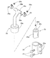
インフレーター25は、図2・3・6に示すように、折り畳まれたエアバッグ10に膨張用ガスGを供給するシリンダタイプとしており、円柱状の本体部25aの上部に複数のガス吐出口25cを備えた頭部25bを配設させて構成されている。インフレーター25は、実施形態の場合、取付ブラケット26を使用して、第1中間ピラー部P1の車体(ボディ1)における車内側Iのインナパネル2に固定されている。また、インフレーター25の上部には、エアバッグ10の後述する二つのガス流入筒部16・17とともに、分岐供給手段36を構成するディフューザー28が結合されている。
【0023】
取付ブラケット26は、板金製として、インフレーター25の本体部25aを挟持してインナパネル2に取り付けるものであり、二本の取付ボルト27を挿通させる取付孔26aを備えて構成されている。取付ボルト27は、取付孔26aを経て、インナパネル2にナット2bを設けて形成した取付孔2aに螺合されることとなる。
【0024】
ディフューザー28は、図2・3・6に示すように、インフレーター25のガス吐出口25cから吐出される膨張用ガスGをエアバッグ10の各ガス流入筒部16・17に案内するものであり、インフレーター本体部25aの上部に嵌め込まれる元部28aと、元部28aの上方で車両の前後方向に分岐する2つの先端部28b・28cと、を備えた三つ又状の金属パイプ材から形成されている。元部28aは、インフレーター本体部25aの上部に溶接・螺合等によって固着されている。各先端部28b・28cには、それぞれ、エアバッグ10の円筒状の各ガス流入筒部16・17が、外装され、かつ、ボルト29aとナット29bとを利用するクランプ29により挟持されて、接続されている。
【0025】
エアバッグカバー4は、図1に示すように、フロントピラー部FPに配置されるピラーガーニッシュ5とルーフサイドレール部RRに配置されるルーフヘッドライニング6とのそれぞれ下縁側のリッド5a・6aから、から構成されている。
【0026】
フロントピラーガーニッシュ5は、合成樹脂製として、フロントピラー部FPの車内側Iにおけるボディ1のインナパネル2に取付固定され、下縁側のリッド5aが、エアバッグ10の展開膨張時、エアバッグ10を突出可能に、車内側Iに開くこととなる。
【0027】
ルーフヘッドライニング6は、図1〜4に示すように、合成樹脂製として、図示しない取付手段によって、ルーフサイドレール部RRの車内側Iにおけるボディ1のインナパネル2に取付固定されている。そして、下縁側のリッド6aが、展開膨張時のエアバッグ10を突出可能に、車内側Iに開くこととなる。なお、リッド6aの下端6bは、図1〜3に示すように、リヤピラー部RP・第1・2中間ピラー部P1・P2の各ガーニッシュ7・8・9の上端7a・8a・9aの車外側Oに侵入して、それらの上端7a・8a・9aに係止されている。
【0028】
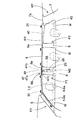
エアバッグ10は、図1・5に示すように、可撓性を有した袋状として、ポリアミド糸等を使用した袋織りによって形成されている。エアバッグ10は、インフレーター25からの膨張用ガスGを流入させて膨らむ膨張部11と、膨張用ガスGを流入させない非膨張部19と、を備えて構成されている。
【0029】
膨張部11は、エアバッグ10の前後方向の略中間部位に位置した第1中間ピラー部P1の部位を境として、前方側の前側膨張部12と、後方側の後側膨張部14と、を備えて構成されている。前側膨張部12と後側膨張部14とは、エアバッグ10の下縁側に配置された連通膨張部13で連通されている。そして、前側膨張部12の後端側上部と後側膨張部14の前端側上部とには、膨張用ガスGを流入させる流入口12a・14aが開口されている。さらに、各流入口12a・14aは、高さ位置を略等しくして、相互に接近するように延びる円筒状のガス流入筒部16・17を一体的に連結させている。
【0030】
各ガス流入筒部16・17は、ディフューザー28とともに、膨張部11に膨張用ガスGを流入させる分岐供給手段36を構成することとなる。そして、ガス流入筒部16は、開口側の先端部16aから元部16bに向う軸方向を、前側膨張部12に向うように、略水平方向に配置させ、ガス流入筒部17は、開口側の先端部17aから元部17bに向う軸方向を、後側膨張部14に向うように、略水平方向に配置させている。
【0031】
非膨張部19は、膨張部11の外周縁で気密性を確保できるように密に織成される周縁部20と、膨張時の膨張部12・14内を区画するように配置されて、膨張部12・14の厚さを各部で略均等にするための規制部22と、板状部23と、を備えて構成されている。規制部22は、膨張部12・14の車内側壁部11aと車外側壁部11bとを結合させるように形成されており、前側膨張部12の領域内では、周縁部20から離れて大小2個形成されるとともに、後側膨張部14の領域内では、周縁部20から離れて大小3個形成されている。
【0032】
板状部23は、エアバッグ10の全体形状を確保して、膨張部11の容積を低減させるために、設けられており、エアバッグ10の前部側の略三角板状の前板状部23aと、後部側の略長方形板状の後板状部23bと、から構成されている。これらの板状部23a・23bは、膨張部11と接していないため、粗く織成されている。
【0033】
そして、エアバッグ10の上縁10a側には、周縁部20から上方へ延びる複数(実施形態では6個)の取付部21が形成されている。各取付部21には、それぞれ、中央に、取付ボルト32(図2・4参照)を挿通させる取付孔21aが袋織り後の孔明け加工により形成されている。
【0034】
各取付部21には、図1・2・4に示すように、折り畳まれたエアバッグ10をボディ1側のインナパネル2に取り付けるための板金製の取付ブラケット31が固定されることとなる。
【0035】
取付ブラケット31は、図1・2・4に示すように、板金製として、各取付部21を挟持するもので、それぞれ、車内側Iの内プレート31aと車外側Oの外プレート31bとを備えて構成され、内・外プレート31a・31bには、各取付部21の取付孔21aに対応する取付孔31cが貫通されている。そして、図4に示すように、取付ボルト32を、取付孔31c・21aに挿通させて、インナパネル2の取付孔2c周縁に固着されたナット2dに螺合させることにより、各取付部21がインナパネル2に取り付けられることとなる。
【0036】
また、第1・2中間ピラー部P1・P2・リヤピラー部RPの上方におけるルーフサイドレール部RRの部位には、図3に示すように、エアバッグ10の展開膨張時に、エアバッグ10がピラーガーニッシュ7・8・9の車外側Oに侵入しないように、縦板部34aと横板部34bとを備えた断面略L字状の板金製の遮蔽板34が、インナパネル2に固着されて配設されている。なお、第1中間ピラー部P1の部位に配置される遮蔽板34には、横板部34bから縦板部34aにかけて、ディフューザー28と干渉しないように、凹部34cが設けられている。これらの遮蔽板34は、実施形態の場合、インナパネル2に溶接されているが、取付ブラケット31の外プレート31bと一体的に形成して、後述するエアバッグ組立体を車両に搭載する際、ボルト32を利用して、インナパネル2に取付固定するようにしても良い。
【0037】
つぎに、第1実施形態の頭部保護エアバッグ装置M1の組立てについて説明すると、まず、エアバッグ10を折り畳む。このエアバッグ10を折り畳む際には、図5に示すように、非膨張状態の平らに展開した状態から、エアバッグ10の上縁10aと平行な折目Cを付けて、下縁10b側から上縁10a側に接近するような、略上下方向に折り重ねる蛇腹折りで、折り畳む。さらに、折り畳んだ後には、所定間隔で破断可能な折り崩れ防止用の図示しないテープ材を巻き付けておく。また、折り畳んだ後には、各取付部21にそれぞれ取付ブラケット31を取り付けておく。
【0038】
そして、各ガス流入筒部16・17の折りを解消して、各ガス流入筒部16・17を、インフレーター25に固着させておいたディフューザー28の対応する先端部28b・28cに対して、外装し、かつ、クランプ29・29で締め付けて接続させ、エアバッグ組立体を形成する。
【0039】
その後、各取付ブラケット26・31をインナパネル2の所定位置に配置させ、各取付孔21a・26a・31cを挿通させてボルト27・32止めし、各取付ブラケット26・31をインナパネル2に固定して、エアバッグ組立体をボディ1に取り付ける。ついで、フロントピラーガーニッシュ5やルーフヘッドライニング6をボディ1に取り付け、さらに、リヤピラーガーニッシュ7や第1・2中間ピラーガーニッシュ8・9をボディ1に取り付ければ、頭部保護エアバッグ装置M1を車両に搭載することができる。
【0040】
車両への搭載後、インフレーター25が作動されれば、インフレーター25からの膨張用ガスGは、図2に示すように、ディフューザー28の元部28aから各先端部28b・28cに流れて、前後方向に分岐され、分岐された膨張用ガスGfが、前方に流れて、ガス流入筒部16を経て、流入口12aからエアバッグ10の前側膨張部12内に流入し、分岐された膨張用ガスGbが、後方に流れて、ガス流入筒部17を経て、流入口14aからエアバッグ10の後側膨張部14内に流入される。そして、エアバッグ10の前側・後側膨張部12・14・連通膨張部13が、折りを解消させつつ、膨張し始めて、エアバッグ10は、図示しないテープ材を破断させ、さらに、フロントピラーガーニッシュ5やルーフヘッドライニング6のリッド5a・6aを押し開いて、図1〜4の二点鎖線で示すように、開口Wを覆うように、大きく展開膨張することとなる。
【0041】
そして、第1実施形態の頭部保護エアバッグ装置M1では、エアバッグ10の前後方向の略中間位置に配設されている各流入口12a・14aを経て、分岐供給手段36から供給される膨張用ガスGf・Gbが、それぞれ、前側・後側膨張部12・14へ流れることから、エアバッグ10の前端若しくは後端の末端に膨張用ガスGf・Gbが到達する時間を、エアバッグの一方の端部から膨張用ガスを流入させる場合に比べて、短縮させることが可能となる。
【0042】
また、前側・後側膨張部12・14へ分岐させて膨張用ガスGf・Gbを流すための分岐供給手段36は、前側・後側膨張部12・14の間であるエアバッグ10の前後方向の略中間位置に配置されているだけで、エアバッグ10の前後方向の全域に設けなくとも良いことから、折り畳んだエアバッグ10を、コンパクトにできて、容易に開口Wの周縁に収納できる。
【0043】
したがって、第1実施形態の頭部保護エアバッグ装置M1では、エアバッグ10が前後方向に長くとも、エアバッグ10の膨張完了までの時間を短縮することができ、さらに、折り畳んだエアバッグ10の収納も容易となる。
【0044】
また、第1実施形態の頭部保護エアバッグ装置M1では、エアバッグ10における前側・後側膨張部12・14の各流入口12a・14aに、相互に接近するように延びるガス流入筒部16・17が設けられており、各ガス流入筒部16・17の軸方向を、的確に、前側膨張部12と後側膨張部14とに向けていることから、一層、各ガス流入筒部16・17を経て流入する膨張用ガスGf・Gbを、前側膨張部12と後側膨張部14とのそれぞれの末端まで、素早く到達させることができる。
【0045】
さらに、実施形態では、インフレーター25と各ガス流入筒部16・17とを接続して、インフレーター25からの膨張用ガスGを各ガス流入筒部16・17へ案内可能な三つ又状のディフューザー28を配設させて、二つのガス流入筒部16・17とディフューザー28とによって分岐供給手段36を構成していることから、一つのインフレーター25で、エアバッグ10の前側・後側膨張部12・14を膨張させることができて、各ガス流入筒部16・17にそれぞれインフレーターを接続させる場合に比べて、エアバッグ装置M1の搭載スペースを小さくできるとともに、エアバッグ装置M1の製造コストを低減させることができる。
【0048】
さらに、第1実施形態では、インフレーター25を、フロントピラー部FPとリヤピラー部RPとの間の第1中間ピラー部P1に配設させており、ピラー部P1が、開口Wの上縁側におけるルーフサイドレール部RRより剛性を有していることから、ルーフサイドレール部RRにインフレーターを配設させる場合に比べて、インフレーター25を安定して配設させることができ、インフレーター25の配設部位に車外側から衝撃力が作用しても、インフレーター25を安定して作動させることができる。
【0050】
図7〜9に示す第2実施形態の頭部保護エアバッグ装置M2は、第1実施形態と同様に、三列シートの車両に搭載されるもので、車内側のドアや窓部の開口Wの上縁側周縁におけるフロントピラー部FPから、第1・2中間ピラー部P1・P2を経て、リヤピラー部RP付近までのルーフサイドレール部RRに、折り畳まれたエアバッグ40を長く配設させて、構成されている。
【0051】
頭部保護エアバッグ装置M2は、エアバッグ40、ディフューザー58、当板49、インフレーター25、取付ブラケット26・31、及び、エアバッグカバー4、を備えて構成され、エアバッグ40とディフューザー58とを除いたインフレーター25・取付ブラケット26・31・エアバッグカバー4は、第1実施形態と同様であるため、同一部位には同一符号を付して説明を省略する。
【0052】
ディフューザー58は、図7〜9・11に示すように、第1実施形態のディフューザー28の元部28aを上方へ延ばした形状の略円筒形状とした金属パイプ材から形成されて、インフレーター25とエアバッグ40の後述する連通部47の縦筒部47cとを接続させている。
【0053】
当板49は、遮蔽板48と一体的に形成されており、この遮蔽板48は、図7〜9・11に示すように、第1中間ピラー部P1の上方におけるルーフサイドレール部RRのインナパネル2に取り付けられている。遮蔽板48は、実施形態の場合、第2中間ピラー部P2やリヤピラー部RPに配置させた遮蔽板34の縦板部34aの上部から車内側Iに第二の横板部を設けたような略コ字形状として、縦板部48aと、下横板部48bと、縦板部48aの上部から車内側Iに延びる上横板部48dと、を備えて構成されている。下横板部48bには、後述する連通部47の縦筒部47cと干渉しないように、車内側Iの縁から車外側Oに凹む凹部48cが形成されている。上・下横板部48b・48d間には、エアバッグ40における連通膨張部13付近が、折り畳まれて収納されることとなる。
【0054】
そして、上横板部48dが当板49を構成することとなり、この当板49は、前後方向の略水平方向に配置されて、この当板49とエアバッグ40の後述する連通部47とが、インフレーター25からの膨張用ガスGを前側・後側膨張部12・14側へ分岐させる分岐供給手段68を構成している。この当板49の中央には、膨張用ガスGを前方と後方とに分岐させ易いように、下方へ山形状に突出する凸部48eが形成されている。
【0055】
さらに、縦板部48aの前後方向両端上部には、ボルト32を挿通可能な取付孔48gを備えた取付部48fが設けられており、遮蔽板48は、これらの取付部48fにエアバッグ40の取付部21と取付ブラケット31の内プレート31aとを配置させて、ボルト32を利用して、エアバッグ40ごとインナパネル2に固定されている。
【0056】
エアバッグ40は、図7・10に示すように、第1実施形態のエアバッグ10と同様に、可撓性を有した袋状として、ポリアミド糸等を使用した袋織りによって形成され、さらに、インフレーター25からの膨張用ガスGを流入させて膨らむ前側・後側膨張部12・14・連通膨張部13を有した膨張部11と、膨張用ガスGを流入させない非膨張部19と、を備えて構成されている。このエアバッグ40は、後述する連通部47が、エアバッグ10のガス流入筒部16・17と相違する他、他の部位をエアバッグ10と同様にしており、それらの同様の各部は、同一符号を付して、説明を省略する。
【0057】
そして、連通部47は、エアバッグ40の前後方向の略中間位置における第1中間ピラー部P1の部位で、かつ、連通膨張部13の上方に、三つ又状に配設されている。連通部47は、前側・後側膨張部12・14にそれぞれ連通して、前後方向に同軸上に配置される前・後横筒部47a・47bと、前・後横筒部47a・47bの境界部位47d付近に連通されて下方に延び、下端側を開口させた縦筒部47cと、から構成されている。縦筒部47cは、インフレーター25に固着されたディフューザー58の上端部58aに外装され、クランプ29を利用して、ディフューザー58と接続されている。
【0058】
第2実施形態の頭部保護エアバッグ装置M2の組立ても、第1実施形態と同様に、まず、非膨張状態の平らに展開した状態から、エアバッグ40の上縁40aと平行な折目Cを付けて、下縁40b側から上縁40a側に接近するような、略上下方向に折り重ねる蛇腹折りで、折り畳んで、破断可能な折り崩れ防止用の図示しないテープ材を巻き付けておく。また、折り畳んだ後には、各取付部21にそれぞれ取付ブラケット31を取り付けておくとともに、内プレート31bを利用して、横板部48b・当板49間に折り畳んだエアバッグ40を配設させた状態で、遮蔽板48をエアバッグ40に組み付けておく。なお、この時、当板49の凸部48eを、前・後横筒部47a・47bの境界部位47dに配置させておく。
【0059】
そして、連通部47の縦筒部47cの折りを解消して、縦筒部47cを、インフレーター25に固着させておいたディフューザー58の上端部58aに対して、外装し、かつ、クランプ29で締め付けて接続させ、エアバッグ組立体を形成する。
【0060】
その後、各取付ブラケット26・31・遮蔽板48をインナパネル2の所定位置に配置させ、各取付孔21a・26a・31c・48gを挿通させてボルト27・32止めし、各取付ブラケット26・31・遮蔽板48をインナパネル2に固定して、エアバッグ組立体をボディ1に取り付ける。ついで、フロントピラーガーニッシュ5やルーフヘッドライニング6をボディ1に取り付け、さらに、リヤピラーガーニッシュ7や第1・2中間ピラーガーニッシュ8・9をボディ1に取り付ければ、頭部保護エアバッグ装置M2を車両に搭載することができる。
【0061】
車両への搭載後、インフレーター25が作動されれば、インフレーター25からの膨張用ガスGが、ディフューザー58からエアバッグ連通部47の縦筒部47c内に流れて、上方に流れる。そして、上向きの膨張用ガスGは、図8に示すように、遮蔽板48における当板49の下面に支持された状態の、連通部47における縦筒部47cと対向する対向壁部47eに衝突して、円滑に前後方向に分岐され、分岐された膨張用ガスGfが、前方に流れて、前横筒部47aを経て、流入口12aからエアバッグ40の前側膨張部12内に流入し、また、分岐された膨張用ガスGbが、後方に流れて、後横筒部47bを経て、流入口14aからエアバッグ40の後側膨張部14内に流入される。そして、エアバッグ40の前側・後側膨張部12・14・連通膨張部13が、折りを解消させつつ、膨張し始めて、エアバッグ40は、図示しないテープ材を破断させ、さらに、フロントピラーガーニッシュ5やルーフヘッドライニング6のリッド5a・6aを押し開いて、図7〜9の二点鎖線で示すように、開口Wを覆うように、大きく展開膨張することとなる。
【0062】
そして、第2実施形態のエアバッグ装置M2でも、エアバッグ40の前後方向の略中間位置に配設されている各流入口12a・14aを経て、分岐供給手段68から供給される膨張用ガスGf・Gbが、それぞれ、前側・後側膨張部12・14へ流れることから、エアバッグ40の前端若しくは後端の末端に膨張用ガスGf・Gbが到達する時間を、エアバッグの一方の端部から膨張用ガスを流入させる場合に比べて、短縮させることが可能となる。
【0063】
また、前側・後側膨張部12・14へ分岐させて膨張用ガスGf・Gbを流すための分岐供給手段68は、前側・後側膨張部12・14の間であるエアバッグ40の前後方向の略中間位置に配置されているだけで、エアバッグ40の前後方向の全域に設けなくとも良いことから、折り畳んだエアバッグ40を、コンパクトにできて、容易に開口Wの周縁に収納できる。
【0064】
したがって、第2実施形態の頭部保護エアバッグ装置M2でも、エアバッグ40が前後方向に長くとも、エアバッグ40の膨張完了までの時間を短縮することができ、さらに、折り畳んだエアバッグ40の収納も容易となる。
【0065】
さらに、この第2実施形態でも、分岐供給手段68を、エアバッグ40に配設されて、前側・後側膨張部12・14にそれぞれ連通する前・後横筒部47a・47b及びインフレーター25側に接続される縦筒部47cを有した三つ又状の連通部47と、前・後横筒部47a・47bの境界部位47d付近における縦筒部47cと対向する対向壁部47eの外側面に配置されて、縦筒部47c内に流入する膨張用ガスGを前・後横筒部47a・47bに分岐させて流す当板49と、から構成して、縦筒部47c側に接続される一つのインフレーター25で、エアバッグ40の前側・後側膨張部12・14を膨張させることができ、エアバッグ装置M2の搭載スペースを小さくできるとともに、エアバッグ装置M2の製造コストを低減させることができる。
【0066】
なお、第2実施形態では、連通部47の対向壁部47eを支持する当板49に、山形状の凸部48eを形成しているため、前・後横筒部47a・47bに分岐して流れる膨張用ガスGf・Gbが、円滑に、前後方向に分岐されることとなる。
【0067】
また、第2実施形態では、当板49を断面略コ字形状の遮蔽板48に一体的に形成した場合を示したが、展開膨張時のエアバッグ40が、ピラーガーニッシュ8の車外側に侵入する虞れがない等の場合には、インナパネル2に固着させるように構成して、当板49単体で構成しても良い。
【0068】
さらに、第1・2実施形態では、インフレーター25をフロントピラーFPに近い第1中間ピラー部P1に配設させた場合を示したが、リヤピラー部RPに近い第2中間ピラー部P2にインフレーター25を配置させて、その部位付近に分岐供給手段36・68を配設させても良い。
【0069】
さらにまた、本発明に係る頭部保護エアバッグ装置は、フロントピラー部FPとリヤピラー部RPとの間に二本の中間ピラー部が配設されている場合だけでなく、一本、あるいは、三本以上の中間ピラー部が配設されている車両に搭載することができる。
【図面の簡単な説明】
【図1】本発明に係る第1実施形態の頭部保護エアバッグ装置を示す使用態様概略図である。
【図2】同実施形態の中間ピラー部付近の拡大図である。
【図3】図2の III− III部位の概略拡大断面図である。
【図4】図1のIV−IV部位の概略拡大断面図である。
【図5】同実施形態に使用するエアバッグの非膨張時における展開状態を示す正面図である。
【図6】同実施形態のディフューザーとインフレーターとを示す斜視図である。
【図7】第2実施形態の頭部保護エアバッグ装置を示す使用態様概略図である。
【図8】同実施形態の中間ピラー部付近の拡大図である。
【図9】図8のIX−IX部位の概略拡大断面図である。
【図10】同実施形態に使用するエアバッグの非膨張時における展開状態を示す正面図である。
【図11】同実施形態の当板とインフレーターとを示す斜視図である。
【符号の説明】
10・40…エアバッグ、
11…膨張部、
12…前側膨張部、
12a・14a…流入口、
14…後側膨張部、
16・17…ガス流入筒部、
25…インフレーター、
28…ディフューザー、
36・68…分岐供給手段、
47…連通部、
47a…前横筒部、
47b…後横筒部、
47c…縦筒部、
49…当板、
FP…フロントピラー部、
RP…リヤピラー部、
P1・P2…中間ピラー部、
W…開口、
M1・M2…頭部保護エアバッグ装置。[0001]
BACKGROUND OF THE INVENTION
The present invention relates to a head protection airbag device mounted on an automobile, and more particularly to a head protection airbag device capable of quickly ensuring the inflation completion shape of an airbag.
[0002]
[Prior art and its problems]
Conventionally, in this type of head protection airbag device, as described in Japanese Patent Application Laid-Open No. 11-321532, the airbag has an opening on the inner side of the vehicle on the front pillar portion and the roof side rail portion. Was folded and stored on the peripheral edge on the upper edge side.
[0003]
However, since the inflating gas supplied from the inflator flows in from the one end side of the front end or the rear end, the air bag reaches the end of the air bag away from the inflator. It was inevitable that it took a long time.
[0004]
When the airbag itself is mounted on a vehicle in which a large number of seats are arranged in the front-rear direction of the vehicle, such as three rows, the length of the airbag in the front-rear direction is further increased. Becomes longer and the time required for the inflation gas to reach the end of the airbag becomes longer.
[0005]
In order to deal with the above, as described in WO 96/26087, a duct provided with a gas discharge port opened downward is provided in the entire front-rear direction of the upper edge of the airbag. Then, it can be considered that the inflator is connected to the duct to quickly expand and inflate the entire area of the airbag.
[0006]
However, in the airbag device of the above publication, since the rigid duct is disposed over the entire length of the upper edge of the airbag in the front-rear direction, the storage space for the folded airbag is increased and folded. It was difficult to store the airbag around the opening edge.
[0007]
The present invention solves the above problems, and even if the airbag is long in the front-rear direction, the time required to complete the inflation of the airbag can be shortened, and the folded airbag can be easily stored. An object is to provide a part protection airbag device.
[0008]
[Means for Solving the Problems]
According to the present inventionFirstIn the head protection airbag device, the airbag is folded and arranged on the upper edge side periphery of the opening inside the vehicle from the vicinity of the front pillar portion to the vicinity of the rear pillar portion, and the airbag is inflated for inflating from the inflator. A head protection airbag device configured to inflate and inflate gas so as to cover the opening,
The airbag is disposed on the front side with a substantially intermediate position in the front-rear direction as a boundary, and is disposed on the rear side with a front inflating portion having an inlet through which the inflation gas can flow into the rear end side. A rear inflatable portion having an inflow port through which the expansion gas can flow into the front end side.
Each inflow port of the front side / rear side expansion part is arranged in an upper part between the front side / rear side expansion part, and communicates with a branch supply means capable of supplying the expansion gas to the front side / rear side expansion part. And
The inflator is disposed in a pillar portion between the front pillar portion and the rear pillar portion;
The branch supply means is formed in a three-pronged shape so as to guide the expansion gas from the inflator and branch it to the respective inlets of the front and rear expansion portions,
Each inflow port of the front side / rear side expansion portion includes a gas inflow tube portion extending so as to approach each other,
The branch supply means is
Two gas inflow cylinders;
A diffuser made of a trifurcated metal pipe material that connects the inflator and the gas inflow cylinders and can guide the expansion gas from the inflator to the gas inflow cylinders;
Consisting of
The front and rear inflating portions of the airbag are communicated by a communicating inflating portion disposed on the lower edge side of the airbag,
A vertical plate portion and a horizontal plate on the body side of the roof side rail portion above the pillar portion where the inflator is disposed so that an airbag during deployment and expansion does not enter the outside of the pillar garnish of the pillar portion. A shielding plate having a substantially L-shaped cross section with a portion,
The horizontal plate is provided with a recess so as to prevent interference with the diffuser for guiding the expansion gas from the inflator in the branch supply unit.It is characterized by.
In a second head protection airbag device according to the present invention, the airbag is folded and disposed on the upper edge side periphery of the opening inside the vehicle from the vicinity of the front pillar portion to the vicinity of the rear pillar portion. A head protection airbag device configured to inflate an inflation gas from an inflator into an inflatable portion and to expand and inflate so as to cover the opening,
The airbag is disposed on the front side with a substantially intermediate position in the front-rear direction as a boundary, and is disposed on the rear side with a front inflating portion having an inlet through which the inflation gas can flow into the rear end side. A rear inflatable portion having an inflow port through which the expansion gas can flow into the front end side.
Each inflow port of the front side / rear side expansion part is arranged in an upper part between the front side / rear side expansion part, and communicates with a branch supply means capable of supplying the expansion gas to the front side / rear side expansion part. And
The inflator is disposed in a pillar portion between the front pillar portion and the rear pillar portion;
The branch supply means is
A front / rear horizontal cylinder part connected to each inlet of the front / rear side inflating part and a vertical cylinder part connected to the inflator side provided on the flexible airbag. A trifurcated communication part,
Arranged on the outer surface of the communicating part facing the vertical cylinder part in the vicinity of the boundary portion of the front and rear horizontal cylinder parts, the expansion gas flowing into the vertical cylinder part branches into the front and rear horizontal cylinder parts And letting it flow,
Consisting of
The front and rear inflating portions of the airbag are communicated by a communicating inflating portion disposed on the lower edge side of the airbag,
A vertical plate portion and a horizontal plate on the body side of the roof side rail portion above the pillar portion where the inflator is disposed so that an airbag during deployment and expansion does not enter the outside of the pillar garnish of the pillar portion. A shielding plate having a substantially L-shaped cross section with a portion,
The horizontal plate portion is provided with a recess so as to prevent interference with the vertical tube portion of the communicating portion that guides the expansion gas from the inflator in the branch supply means.
[0012]
【The invention's effect】
In the head protection airbag device according to the present invention, the inflation gas supplied from the branch supply means via the respective inflow ports disposed at substantially intermediate positions in the front-rear direction of the airbag, respectively, Since it flows to the side inflating portion, the time for the inflation gas to reach the front end or the rear end of the airbag can be shortened as compared with the case where the inflation gas flows from one end of the airbag. It becomes possible.
[0013]
Further, the branch supply means for flowing the inflation gas by branching to the front side / rear side inflating part is merely disposed at a substantially intermediate position in the front-rear direction of the airbag between the front side and rear side inflating parts. Since the airbag does not have to be provided in the entire area in the front-rear direction, the folded airbag can be made compact and can be easily stored in the periphery of the opening.
[0014]
Therefore, in the head protection airbag device according to the present invention, even when the airbag is long in the front-rear direction, the time until the airbag is completely inflated can be shortened, and the folded airbag can be easily stored. .
[0015]
And,If each inflow port of the front side / rear side inflating part is provided with a gas inflow cylinder part extending so as to approach each other, the axial direction of each gas inflow cylinder part can be accurately determined in the front side inflating part and the rear side inflating part. It is possible to direct the expansion gas flowing in through each gas inflow cylinder portion to the respective ends of the front expansion portion and the rear expansion portion more quickly. .
[0016]
in this case,The inflator is connected to each gas inflow cylinder, and a diffuser that can guide the expansion gas from the inflator to each gas inflow cylinder is provided, and the two gas inflow cylinders and the diffuser constitute a branch supply means. Then, by connecting one inflator to two gas inflow cylinders, it becomes possible to inflate the front and rear inflatable parts of the airbag, compared to connecting each inflator to each gas inflow cylinder. Thus, the mounting space for the airbag device can be reduced, and the manufacturing cost of the airbag device can be reduced.
[0017]
Also,The branch supply means is disposed in the airbag, and has a trifurcated shape having front and rear horizontal cylindrical portions connected to the respective inlets of the front and rear inflating portions and a vertical cylindrical portion connected to the inflator side. Arranged on the outer surface of the communicating part and the communicating part facing the vertical cylinder part in the vicinity of the boundary between the front and rear horizontal cylinder parts, the expansion gas flowing into the vertical cylinder part is branched into the front and rear horizontal cylinder parts Even if it consists of a contact plate that flows, it is possible to inflate the front and rear inflated portions of the airbag with a single inflator, so that the mounting space for the airbag device can be reduced and the airbag device can be manufactured. Cost can be reduced.
[0018]
further,If the inflator is configured to be disposed in the pillar part between the front pillar part and the rear pillar part, the pillar part has rigidity from the roof side rail part on the upper edge side of the opening, and the roof side rail part has Compared with the case where the inflator is disposed, the inflator can be stably disposed, and the inflator can be stably operated even when an impact force is applied to the disposed portion of the inflator from the outside of the vehicle.
[0019]
DETAILED DESCRIPTION OF THE INVENTION
Hereinafter, an embodiment of the present invention will be described with reference to the drawings.
[0020]
The head protection airbag device M1 of the first embodiment shown in FIGS. 1 to 5 is mounted on a three-row seat vehicle as shown in FIG. The folded
[0021]
The head protecting airbag device M1 includes the
[0022]
As shown in FIGS. 2, 3, and 6, the
[0023]
The mounting
[0024]
The
[0025]
As shown in FIG. 1, the
[0026]
The
[0027]
As shown in FIGS. 1 to 4, the roof head lining 6 is made of synthetic resin and is fixedly attached to the
[0028]
As shown in FIGS. 1 and 5, the
[0029]
The inflating part 11 includes a front inflating part 12 on the front side and a
[0030]
The
[0031]
The
[0032]
The plate-like portion 23 is provided in order to secure the overall shape of the
[0033]
A plurality (six in the embodiment) of
[0034]
As shown in FIGS. 1, 2, and 4, a mounting
[0035]
As shown in FIGS. 1, 2, and 4, the mounting
[0036]
Further, as shown in FIG. 3, when the
[0037]
Next, the assembly of the head protection airbag device M1 of the first embodiment will be described. First, the
[0038]
Then, the folding of the
[0039]
Thereafter, the mounting
[0040]
If the
[0041]
In the head protection airbag device M1 of the first embodiment, the inflation supplied from the branch supply means 36 via the
[0042]
Further, the branch supply means 36 for branching the front and rear inflating
[0043]
Therefore, in the head protection airbag device M1 of the first embodiment, even if the
[0044]
Further, in the head protection airbag device M1 of the first embodiment, the gas
[0045]
Further, in the embodiment, a trifurcated
[0048]
Further, in the first embodiment, the
[0050]
The head protection airbag device M2 of the second embodiment shown in FIGS. 7 to 9 is mounted on a three-row seat vehicle as in the first embodiment, and is provided with an opening W of a door or a window portion on the inside of the vehicle. The folded
[0051]
The head protecting airbag device M2 includes an
[0052]
As shown in FIGS. 7 to 9 and 11, the
[0053]
The
[0054]
The upper
[0055]
Further,
[0056]
As shown in FIGS. 7 and 10, the
[0057]
The
[0058]
Even in the assembly of the head protection airbag device M2 of the second embodiment, the fold C parallel to the
[0059]
Then, the folding of the vertical
[0060]
Thereafter, the mounting
[0061]
If the
[0062]
Also in the airbag apparatus M2 of the second embodiment, the inflation gas Gf supplied from the branch supply means 68 via the
[0063]
Further, the branch supply means 68 for branching to the front and
[0064]
Therefore, even in the head protecting airbag device M2 of the second embodiment, even if the
[0065]
Further, also in the second embodiment, the branch supply means 68 is disposed in the
[0066]
In the second embodiment, since the
[0067]
In the second embodiment, the case where the
[0068]
Further, in the first and second embodiments, the case where the inflator 25 is disposed in the first intermediate pillar portion P1 close to the front pillar FP is shown, but the
[0069]
Furthermore, the head protection airbag device according to the present invention is not limited to the case where two intermediate pillar portions are disposed between the front pillar portion FP and the rear pillar portion RP, but also one or three. It can be mounted on a vehicle having more than one intermediate pillar portion.
[Brief description of the drawings]
BRIEF DESCRIPTION OF DRAWINGS FIG. 1 is a schematic view of a usage pattern showing a head protection airbag device according to a first embodiment of the present invention.
FIG. 2 is an enlarged view of the vicinity of an intermediate pillar portion of the embodiment.
FIG. 3 is a schematic enlarged cross-sectional view taken along a line III-III in FIG.
4 is a schematic enlarged cross-sectional view of the IV-IV portion of FIG. 1. FIG.
FIG. 5 is a front view showing a deployed state when the airbag used in the embodiment is not inflated;
FIG. 6 is a perspective view showing a diffuser and an inflator according to the embodiment.
FIG. 7 is a schematic view showing how the head protection airbag device according to the second embodiment is used.
FIG. 8 is an enlarged view of the vicinity of the intermediate pillar portion of the embodiment.
9 is a schematic enlarged cross-sectional view of a portion IX-IX in FIG.
FIG. 10 is a front view showing a deployed state when the airbag used in the embodiment is not inflated.
FIG. 11 is a perspective view showing the contact plate and the inflator according to the embodiment.
[Explanation of symbols]
10.40 ... Airbag,
11 ... inflatable part,
12 ... front side expansion part,
12a, 14a ... Inlet,
14 ... rear expansion part,
16.17 ... Gas inflow cylinder,
25 ... Inflator,
28 ... Diffuser,
36.68 ... branch supply means,
47. Communication part,
47a ... Front horizontal cylinder part,
47b ... rear horizontal cylinder part,
47c ... Vertical cylinder part,
49 ... this board,
FP ... Front pillar part,
RP ... Rear pillar part,
P1, P2 ... Intermediate pillar part,
W ... Opening,
M1, M2 ... Head protection airbag device.
Claims (2)
前記エアバッグが、前後方向の略中間位置を境にして、前部側に配置されて後端側に前記膨張用ガスを流入可能な流入口を有した前側膨張部と、後部側に配置されて前端側に前記膨張用ガスを流入可能な流入口を有した後側膨張部と、を備えて構成され、
前記前側・後側膨張部の各流入口が、前記前側・後側膨張部の間の上部に配置されて、前記膨張用ガスを前記前側・後側膨張部へ供給可能な分岐供給手段と連通され、
前記インフレーターが、前記フロントピラー部と前記リヤピラー部との間のピラー部に配設され、
前記分岐供給手段が、前記インフレーターからの膨張用ガスを案内して前側・後側膨張部の各流入口に分岐させるように、三又状に形成され、
前記前側・後側膨張部の各流入口が、相互に接近するように延びるガス流入筒部を備え、
前記分岐供給手段が、
二つの前記ガス流入筒部と、
前記インフレーターと前記各ガス流入筒部とを接続して、前記インフレーターからの膨張用ガスを前記各ガス流入筒部へ案内可能な三つ又状の金属パイプ材からなるディフューザーと、
から構成され、
前記エアバッグの前記前側・後側膨張部が、前記エアバッグの下縁側に配置された連通膨張部によって連通され、
前記インフレーターの配設されているピラー部の上方のルーフサイドレール部のボディ側に、展開膨張時のエアバッグが前記ピラー部のピラーガーニッシュにおける車外側へ侵入しないように、縦板部と横板部とを備えた断面略L字形の遮蔽板が、固着され、
前記横板部に、前記分岐供給手段における前記インフレーターからの膨張用ガスを案内する前記ディフューザーとの干渉を防止するように、凹部が設けられていることを特徴とする頭部保護エアバッグ装置。An airbag is folded and arranged at the upper edge side periphery of the opening inside the vehicle from the vicinity of the front pillar portion to the vicinity of the rear pillar portion, and an inflation gas from an inflator is caused to flow into the inflation portion of the airbag to A head protection airbag device configured to be deployed and inflated to cover
The airbag is disposed on the front side with a substantially intermediate position in the front-rear direction as a boundary, and is disposed on the rear side with a front inflating portion having an inlet through which the inflation gas can flow into the rear end side. A rear inflatable portion having an inflow port through which the expansion gas can flow into the front end side.
Each inflow port of the front side / rear side expansion part is arranged in an upper part between the front side / rear side expansion part, and communicates with a branch supply means capable of supplying the expansion gas to the front side / rear side expansion part. And
The inflator is disposed in a pillar portion between the front pillar portion and the rear pillar portion;
The branch supply means is formed in a three-pronged shape so as to guide the expansion gas from the inflator and branch it to the respective inlets of the front and rear expansion portions,
Each inflow port of the front side / rear side expansion portion includes a gas inflow tube portion extending so as to approach each other,
The branch supply means is
Two gas inflow cylinders;
A diffuser made of a trifurcated metal pipe material that connects the inflator and the gas inflow cylinders and can guide the expansion gas from the inflator to the gas inflow cylinders;
Consisting of
The front and rear inflating portions of the airbag are communicated by a communicating inflating portion disposed on the lower edge side of the airbag,
A vertical plate portion and a horizontal plate on the body side of the roof side rail portion above the pillar portion where the inflator is disposed so that an airbag during deployment and expansion does not enter the outside of the pillar garnish of the pillar portion. A shielding plate having a substantially L-shaped cross section with a portion,
The head protection airbag device according to claim 1, wherein a concave portion is provided in the horizontal plate portion so as to prevent interference with the diffuser that guides the inflation gas from the inflator in the branch supply means .
前記エアバッグが、前後方向の略中間位置を境にして、前部側に配置されて後端側に前記膨張用ガスを流入可能な流入口を有した前側膨張部と、後部側に配置されて前端側に前記膨張用ガスを流入可能な流入口を有した後側膨張部と、を備えて構成され、
前記前側・後側膨張部の各流入口が、前記前側・後側膨張部の間の上部に配置されて、前記膨張用ガスを前記前側・後側膨張部へ供給可能な分岐供給手段と連通され、
前記インフレーターが、前記フロントピラー部と前記リヤピラー部との間のピラー部に配設され、
前記分岐供給手段が、
可撓性を有した前記エアバッグに配設されて、前記前側・後側膨張部の各流入口とそれぞれ接続される前・後横筒部及び前記インフレーター側に接続される縦筒部を有した三つ又状の連通部と、
前記前・後横筒部の境界部位付近における前記縦筒部と対向する前記連通部の外側面に配置されて、前記縦筒部内に流入する膨張用ガスを前記前・後横筒部に分岐させて流す当板と、
から構成され、
前記エアバッグの前記前側・後側膨張部が、前記エアバッグの下縁側に配置された連通 膨張部によって連通され、
前記インフレーターの配設されているピラー部の上方のルーフサイドレール部のボディ側に、展開膨張時のエアバッグが前記ピラー部のピラーガーニッシュにおける車外側へ侵入しないように、縦板部と横板部とを備えた断面略L字形の遮蔽板が、固着され、
前記横板部に、前記分岐供給手段における前記インフレーターからの膨張用ガスを案内する前記連通部の前記縦筒部との干渉を防止するように、凹部が設けられていることを特徴とする頭部保護エアバッグ装置。An airbag is folded and arranged at the upper edge side periphery of the opening inside the vehicle from the vicinity of the front pillar portion to the vicinity of the rear pillar portion, and an inflation gas from an inflator is caused to flow into the inflation portion of the airbag to A head protection airbag device configured to be deployed and inflated to cover
The airbag is disposed on the front side with a substantially intermediate position in the front-rear direction as a boundary, and is disposed on the rear side with a front inflating portion having an inlet through which the inflation gas can flow into the rear end side. A rear inflatable portion having an inflow port through which the expansion gas can flow into the front end side.
Each inflow port of the front side / rear side expansion part is arranged in an upper part between the front side / rear side expansion part, and communicates with a branch supply means capable of supplying the expansion gas to the front side / rear side expansion part. And
The inflator is disposed in a pillar portion between the front pillar portion and the rear pillar portion;
The branch supply means is
A front / rear horizontal cylinder part connected to each inlet of the front / rear side inflating part and a vertical cylinder part connected to the inflator side provided on the flexible airbag. A trifurcated communication part,
Arranged on the outer surface of the communicating part facing the vertical cylinder part in the vicinity of the boundary portion of the front and rear horizontal cylinder parts, the expansion gas flowing into the vertical cylinder part branches into the front and rear horizontal cylinder parts And letting it flow,
Consisting of
The front and rear inflating portions of the airbag are communicated by a communicating inflating portion disposed on the lower edge side of the airbag ,
A vertical plate portion and a horizontal plate on the body side of the roof side rail portion above the pillar portion where the inflator is disposed so that an airbag during deployment and expansion does not enter the outside of the pillar garnish of the pillar portion. A shielding plate having a substantially L-shaped cross section with a portion,
The head is characterized in that a concave portion is provided in the horizontal plate portion so as to prevent interference with the vertical cylinder portion of the communication portion that guides the expansion gas from the inflator in the branch supply means. Part protection airbag device.
Priority Applications (1)
| Application Number | Priority Date | Filing Date | Title |
|---|---|---|---|
| JP2000094672A JP3900787B2 (en) | 2000-03-30 | 2000-03-30 | Head protection airbag device |
Applications Claiming Priority (1)
| Application Number | Priority Date | Filing Date | Title |
|---|---|---|---|
| JP2000094672A JP3900787B2 (en) | 2000-03-30 | 2000-03-30 | Head protection airbag device |
Publications (3)
| Publication Number | Publication Date |
|---|---|
| JP2001277987A JP2001277987A (en) | 2001-10-10 |
| JP2001277987A5 JP2001277987A5 (en) | 2005-05-26 |
| JP3900787B2 true JP3900787B2 (en) | 2007-04-04 |
Family
ID=18609693
Family Applications (1)
| Application Number | Title | Priority Date | Filing Date |
|---|---|---|---|
| JP2000094672A Expired - Lifetime JP3900787B2 (en) | 2000-03-30 | 2000-03-30 | Head protection airbag device |
Country Status (1)
| Country | Link |
|---|---|
| JP (1) | JP3900787B2 (en) |
Families Citing this family (7)
| Publication number | Priority date | Publication date | Assignee | Title |
|---|---|---|---|---|
| JP4696417B2 (en) * | 2001-07-25 | 2011-06-08 | トヨタ自動車株式会社 | Head protection airbag mounting structure |
| JP2004168287A (en) * | 2002-10-29 | 2004-06-17 | Daicel Chem Ind Ltd | Inflator for airbag |
| US7052037B2 (en) | 2002-10-29 | 2006-05-30 | Daicel Chemical Industrials, Ltd. | Inflator for air bag |
| JP2008056119A (en) * | 2006-08-31 | 2008-03-13 | Toyota Motor Corp | Head protection airbag device |
| JP5627200B2 (en) * | 2009-06-03 | 2014-11-19 | 日本プラスト株式会社 | Airbag device |
| CN102256835B (en) * | 2010-03-04 | 2014-01-08 | 丰田自动车株式会社 | Arrangement structure for curtain airbag device |
| CN114834384B (en) * | 2022-05-23 | 2023-11-21 | 一汽奔腾轿车有限公司 | Curtain type safety airbag, control method and automobile |
-
2000
- 2000-03-30 JP JP2000094672A patent/JP3900787B2/en not_active Expired - Lifetime
Also Published As
| Publication number | Publication date |
|---|---|
| JP2001277987A (en) | 2001-10-10 |
Similar Documents
| Publication | Publication Date | Title |
|---|---|---|
| JP3835257B2 (en) | Head protection airbag device | |
| JP3835264B2 (en) | Head protection airbag device | |
| US6502854B2 (en) | Air bag device, production method of an air bag device, activation method of an air bag device and vehicle with an air bag device | |
| JP3700054B2 (en) | Airbag device | |
| US7080853B2 (en) | Airbag for head-protecting airbag device | |
| US7163233B2 (en) | Head-protecting airbag | |
| JPH11235965A (en) | Head protection airbag device | |
| JP3718763B2 (en) | Head protection airbag device | |
| JP5201089B2 (en) | Head protection airbag device | |
| JP3900787B2 (en) | Head protection airbag device | |
| JP3487266B2 (en) | Head protection airbag device | |
| JP2010235043A (en) | Airbag device | |
| JP5435913B2 (en) | Airbag device | |
| EP1167129B1 (en) | Air bag | |
| JP3671874B2 (en) | Head protection airbag device | |
| JP3858675B2 (en) | Head protection airbag device | |
| JP2001328505A (en) | Air bag device | |
| JP2005239038A (en) | Air bag | |
| JP2002316609A (en) | Head protective airbag device | |
| JP3702830B2 (en) | Knee protection airbag device | |
| JP4465935B2 (en) | Head protection airbag device | |
| JP2001277987A5 (en) | ||
| JP2003048503A (en) | Heat part protection air bag device | |
| JP5029578B2 (en) | Head protection airbag device | |
| JP3689845B2 (en) | Head protection airbag device airbag |
Legal Events
| Date | Code | Title | Description |
|---|---|---|---|
| A521 | Written amendment |
Free format text: JAPANESE INTERMEDIATE CODE: A523 Effective date: 20040802 |
|
| A621 | Written request for application examination |
Free format text: JAPANESE INTERMEDIATE CODE: A621 Effective date: 20040802 |
|
| A131 | Notification of reasons for refusal |
Free format text: JAPANESE INTERMEDIATE CODE: A131 Effective date: 20060725 |
|
| A521 | Written amendment |
Free format text: JAPANESE INTERMEDIATE CODE: A523 Effective date: 20060919 |
|
| TRDD | Decision of grant or rejection written | ||
| A01 | Written decision to grant a patent or to grant a registration (utility model) |
Free format text: JAPANESE INTERMEDIATE CODE: A01 Effective date: 20061212 |
|
| A61 | First payment of annual fees (during grant procedure) |
Free format text: JAPANESE INTERMEDIATE CODE: A61 Effective date: 20061225 |
|
| R150 | Certificate of patent or registration of utility model |
Free format text: JAPANESE INTERMEDIATE CODE: R150 Ref document number: 3900787 Country of ref document: JP Free format text: JAPANESE INTERMEDIATE CODE: R150 |
|
| FPAY | Renewal fee payment (event date is renewal date of database) |
Free format text: PAYMENT UNTIL: 20100112 Year of fee payment: 3 |
|
| FPAY | Renewal fee payment (event date is renewal date of database) |
Free format text: PAYMENT UNTIL: 20110112 Year of fee payment: 4 |
|
| FPAY | Renewal fee payment (event date is renewal date of database) |
Free format text: PAYMENT UNTIL: 20120112 Year of fee payment: 5 |
|
| FPAY | Renewal fee payment (event date is renewal date of database) |
Free format text: PAYMENT UNTIL: 20130112 Year of fee payment: 6 |
|
| FPAY | Renewal fee payment (event date is renewal date of database) |
Free format text: PAYMENT UNTIL: 20140112 Year of fee payment: 7 |
|
| EXPY | Cancellation because of completion of term |