JP3899780B2 - Tube fastening structure - Google Patents
Tube fastening structure Download PDFInfo
- Publication number
- JP3899780B2 JP3899780B2 JP2000140833A JP2000140833A JP3899780B2 JP 3899780 B2 JP3899780 B2 JP 3899780B2 JP 2000140833 A JP2000140833 A JP 2000140833A JP 2000140833 A JP2000140833 A JP 2000140833A JP 3899780 B2 JP3899780 B2 JP 3899780B2
- Authority
- JP
- Japan
- Prior art keywords
- tube
- annular
- peripheral surface
- fastening structure
- engagement end
- Prior art date
- Legal status (The legal status is an assumption and is not a legal conclusion. Google has not performed a legal analysis and makes no representation as to the accuracy of the status listed.)
- Expired - Fee Related
Links
Images


Classifications
-
- F—MECHANICAL ENGINEERING; LIGHTING; HEATING; WEAPONS; BLASTING
- F16—ENGINEERING ELEMENTS AND UNITS; GENERAL MEASURES FOR PRODUCING AND MAINTAINING EFFECTIVE FUNCTIONING OF MACHINES OR INSTALLATIONS; THERMAL INSULATION IN GENERAL
- F16L—PIPES; JOINTS OR FITTINGS FOR PIPES; SUPPORTS FOR PIPES, CABLES OR PROTECTIVE TUBING; MEANS FOR THERMAL INSULATION IN GENERAL
- F16L21/00—Joints with sleeve or socket
- F16L21/08—Joints with sleeve or socket with additional locking means
Landscapes
- Engineering & Computer Science (AREA)
- General Engineering & Computer Science (AREA)
- Mechanical Engineering (AREA)
- Clamps And Clips (AREA)
- Joints That Cut Off Fluids, And Hose Joints (AREA)
- Rigid Pipes And Flexible Pipes (AREA)
Description
【0001】
【発明の属する技術分野】
本発明は、チューブと樹脂及び金属等からなる剛性のパイプ等の菅状の相手部材とを流体密に接続したチューブの締結構造に係わる。例えば耐ガソリン性が要求される自動車用のチューブと金属製パイプの締結構造に好適に用いられる。
【0002】
【従来の技術】
従来、この種の締結構造としては、特開平4−171391号に記載されたものが知られている。即ち、図10に示すように、金属チューブ5の接続部外周部に薄肉チューブ7の接続部をはめ合わせ、この薄肉チューブ7の接続部外周部に、この薄肉チューブ7と同材質の保護スリーブ6をはめ合わせ、この保護スリーブ6の接続部外周部を互いに間隔を空けた2カ所以上で金属製スリーブ8により、加締め付ける薄肉チューブ7と金属チューブ5との接続構造であり、また、前記金属チューブ5の外周部に2カ所以上の加締め部のうちのいずれかの加締め部の位置の少なくとも1カ所に溝5aを設け、さらにまた、前記溝5aの寸法が、薄肉チューブの肉厚の1/2よりも小さい寸法の深さで、金属製スリーブ8の1カ所の加締め部の幅寸法よりも小さい幅寸法であることにより構成されている。
【0003】
【発明が解決しようとする課題】
しかしながら、上記薄肉チューブ7は比較的硬質の樹脂が採用されるため、チューブの内周面と金属チューブ5の外周面とのシール性が劣るという問題を有していた。従って、シール性を高めるために外周からスリーブで強く加締める構造が採用されるが、このような加締め作業は、加締装置を必要とするため、自動車等の組み立て現場では採用することは困難である。また、締め付けの際に発生するシワにより、流体漏れが起こるという問題を有していた。
【0004】
本発明は、かかる事情に鑑み、チューブと管状の相手部材とのシール性を容易に高めることができ、しかも、自動車の組み立て現場等、あらゆる所で容易に接続できるチューブ接続体を提供することを第1の目的とする。
【0005】
本発明の他の目的は、締め付けの際に発生するシワによる、流体漏れを防止するチューブ接続体を提供することを目的とする。
【0006】
【課題を解決するための手段及び発明の効果】
上記目的を達成するために、本発明の第1の構成上の特徴(請求項1に対応)は、チューブの一端に相手部材を接続するためのチューブの締結構造体であって、 一端から他端に延びるチューブと、内周面に一端面から軸方向に距離を隔てた位置に形成された環状凹部を有するチューブの一端に形成された係合端部と、チューブの係合端部に挿着された筒状の弾性シール部材と、先端から距離を隔てた位置に、その外周面から軸方向外方に突出した環状突起部を有し、弾性シール部材の内周に挿入可能な挿入端部を備えた管状の相手部材と、チューブの外周に環状に配置された締結部材とを備え、弾性シール部材はチューブの係合端部の内周面に嵌着された外周面をもつ内筒部と、内筒部一端側に係合端部の一端面を覆うと共に係合端部の外周面を覆うように外側に曲げ返されている外筒部とを備え、且つ、内筒部の外周面にチューブの環状凹部に適合した環状の嵌合凸部と内周面に相手部材の環状突起部が嵌合する環状の嵌合凹部を備え、相手部材の挿入端部が、筒状の弾性シール部材の内周面に挿着された状態で、外筒部の外周に、締結部材が締結されており、係合端部の中間に、係合端部の外周面から径方向外方に突出した環状凸部を備えていることを特徴とするチューブの締結構造体を構成したものである。
【0007】
本発明は上述したように、チューブが一端面から軸方向に距離を隔てた位置に形成された環状凹部を有する係合端部を備え、筒状の弾性シール部材がチューブの係合端部の内周面に挿着された外周面をもつ内筒部と、内筒部一端側に係合端部の端面を覆うと共に係合端部の外周面を覆うように外側に曲がった外筒部とを備え、且つ、内筒部の外周面にチューブの環状凹部に適合した嵌合凸部と内周面に相手部材の環状突起部が嵌合する嵌合凹部を備えているので、相手部材は筒状の弾性シール部材に対して軸方向に移動しないように保持されている。そしてこの筒状の弾性シール部材はチューブに対して軸方向に移動しないように保持されている。
また、チューブの一端は弾性シール部材の内筒部と外筒部間に挟持され、外筒部の外周から締結部材で締結されている。従って、相手部材はチューブから抜けるのを防止できる。
【0008】
また、係合端部の中間に、係合端部の外周面から径方向外方に突出した環状凸部を備えていることにより、締結の際に係合端部に発生するシワを環状凸部で留めることができるため、チューブの係合端部と弾性シール部材の内筒部と相手部材の挿入端部間のシール性を高めることができる。
【0009】
また、本発明の第2の構成上の特徴(請求項2に対応)は、前記第1の特徴において、係合端部の内周面に形成された環状凹部が、係合端部の中間部に形成され、締結部材が環状凸部より一端側位置に配置され、弾性シール部材の内筒部が内筒部の環状の嵌合凸部から、軸方向内方に伸びた延長部を備えていることにある。このように、弾性シール部材の内筒部が延長部を備えたことにより、延長部は締結部材が締結される部分から離れた部分にあるため、締結の影響を受けることなく係合端部間のシールが確実に行われる。
【0010】
また、本発明の第3の構成上の特徴(請求項3に対応)は、前記第1又は第2の特徴において、チューブの係合端部の環状凹部と一端面間が周方向に波形を有する波形筒状部に形成されていることにある。これにより、締結部材が締結される部分において波形筒状部によりしわの発生を吸収できるため、締結部分におけるシール性が確保され、流体洩れを確実に防止できる。
【0011】
また、本発明の第4の構成上の特徴(請求項4に対応)は、前記第1又は第2の特徴において、チューブの係合端部の周方向の少なくとも一ヶ所にて、一端面から環状凹部方向に延びるスリットを設けたことにある。これにより、締結部材が締結される部分においてスリットによりしわの発生を吸収できるため、締結部分におけるシール性が確保され、流体洩れを確実に防止できる。また、波形筒状部よりスリットの形成は容易である。
【0012】
また、本発明の第5の構成上の特徴(請求項5に対応)は、前記第1、第2、第3又は第4の特徴において、内筒部の軸方向内端部が、厚さ方向の中間位置にて分岐して互いに径方向外方及び内方に向けて傾斜して延びる環状の外分岐部及び内分岐部になっていることにある。これにより、内筒部は外分岐部において係合端部と緊密に接触してシール性が良好に確保され、内分岐部においては相手部材と緊密に接触してシール性が良好に確保される。
【0013】
また、本発明の第6の構成上の特徴(請求項6に対応)は、前記第1、第2、第3、第4又は第5の特徴において、内筒部は、環状の嵌合凹部から軸方向外方に延びる基部と嵌合凹部から軸方向内方に延びる延長部を備え、基部が相手部材の挿入端部の外径よりもやや大きい内径を有する一方、延長部が相手部材の挿入端部の外径よりもやや小さい内径を有することにある。これにより、挿入端部の基部への挿入を容易にすることができ、一方、延長部においては弾性シール部材と挿入端部とのシール性を高めることができる。
【0014】
また、本発明の第7の構成上の特徴(請求項7に対応)は、前記第1、第2、第3、第4、第5又は第6の特徴において、内筒部の延長部の外周面及び内周面にて軸方向の複数箇所に、径方向外方及び内方に向けて同軸的に突出した環状の突出シール部を設けたことにある。これにより、内筒部は外方に突出した突出シール部により係合端部と緊密に接触してシール性が良好に確保され、また内方に突出した突出シール部により相手部材と緊密に接触してシール性が良好に確保される。
【0015】
また、本発明の第8の構成上の特徴(請求項8に対応)は、前記第1、第2、第3、第4、第5、第6又は第7の特徴において、チューブの構造が、樹脂の単層構造、内層が樹脂,導電性樹脂あるいは金属膜であり外層が樹脂である2層構造、あるいは内層及び外層の中間に接着剤層を設けた3層構造の内のいずれかであることにある。これにより、チューブの構造が、用途に応じて種々選択可能になる。
【0016】
また、本発明の第9の構成上の特徴(請求項9に対応)は、チューブの一端に相手部材を接続するためのチューブの締結構造体であって、一端から他端に延びるチューブと、内周面に一端面から軸方向に距離を隔てた位置に形成された環状凹部を有するチューブの一端に形成された、軸方向に延びている係合端部と、チューブの係合端部に挿着された筒状の弾性シール部材と、先端から距離を隔てた位置に、その外周面から軸方向外方に突出した環状突起部を有し、弾性シール部材の内周に挿入可能な挿入端部を備えた管状の相手部材と、チューブの外周に環状に配置された締結部材とを備え、弾性シール部材はチューブの係合端部の一端面のみを覆うと共に係合端部の内周面に嵌着された外周面をもつ内筒部を備え、且つ、内筒部の外周面にチューブの環状凹部に適合した環状の嵌合凸部と内周面に相手部材の環状突起部が嵌合する環状の嵌合凹部を備え、相手部材の挿入端部が、筒状の弾性シール部材の内周面に挿着された状態で、係合端部の外周に、締結部材が締結されており、係合端部の中間に、係合端部の外周面から径方向外方に突出した環状凸部を備えていることにある。本発明は、上記第1の構成において、弾性シール部材の外筒部を無くしたものであり、これにより、第1の構成の効果に加えて、弾性シール部材のチューブへの挿入を容易に行うことができる。
【0017】
また、係合端部の中間に、係合端部の外周面から径方向外方に突出した環状凸部を備えていることにより、締結の際に係合端部に発生するシワを環状凸部で留めることができるため、チューブの係合端部と弾性シール部材の内筒部と相手部材の挿入端部間のシール性を高めることができる。
【0018】
また、本発明の第10の構成上の特徴(請求項10に対応)は、前記第9の特徴において、係合端部の内周面に形成された環状凹部が、係合端部の中間部に形成され、締結部材が環状凸部より一端側位置に配置され、弾性シール部材の内筒部が内筒部の環状の嵌合凸部から、軸方向内方に伸びた延長部を備えていることにある。このように、弾性シール部材の内筒部が延長部を備えたことにより、延長部は締結部材が締結される部分から離れた部分にあるため、締結の影響を受けることなく係合端部間のシールが確実に行われる。
【0019】
また、本発明の第11の構成上の特徴(請求項11に対応)は、前記第9又は第10の特徴において、チューブの係合端部の環状凹部と一端面間が周方向に波形を有する波形筒状部に形成されていることにある。これにより、締結部材が締結される部分において波形筒状部によりしわの発生を吸収できるため、締結部分におけるシール性が確保され、流体洩れを確実に防止できる。
【0020】
また、本発明の第12の構成上の特徴(請求項12に対応)は、前記第9又は第10の特徴において、チューブの係合端部の周方向の少なくとも一ヶ所にて、一端面から環状凹部方向に延びるスリットを設けたことにある。これにより、締結部材が締結される部分においてスリットによりしわの発生を吸収できるため、締結部分におけるシール性が確保され、流体洩れを確実に防止できる。また、係合端部にスリットを形成することは容易である。
【0021】
また、本発明の第13の構成上の特徴(請求項13に対応)は、前記第9、第10、第11又は第12の特徴において、内筒部の軸方向内端部が、厚さ方向の中間位置にて分岐して互いに径方向外方及び内方に向けて傾斜して延びる環状の外分岐部及び内分岐部になっていることにある。これにより、内筒部は外分岐部において係合端部と緊密に接触してシール性が良好に確保され、内分岐部においては相手部材と緊密に接触してシール性が良好に確保される。
【0022】
また、本発明の第14の構成上の特徴(請求項14に対応)は、前記第9、第10、第11、第12又は第13の特徴において、内筒部は、環状の嵌合凹部から軸方向外方に延びる基部と嵌合凹部から軸方向内方に延びる延長部を備え、基部が相手部材の挿入端部の外径よりもやや大きい内径を有する一方、延長部が相手部材の挿入端部の外径よりもやや小さい内径を有することにある。これにより、挿入端部の基部への挿入を容易にすることができ、一方延長部において弾性シール部材と挿入端部とのシール性を高めることができる。
【0023】
また、本発明の第15の構成上の特徴(請求項15に対応)は、前記第9、第10、第11、第12、第13又は第14の特徴において、内筒部の延長部の外周面及び内周面にて軸方向の複数箇所に、径方向外方及び内方に向けて同軸的に突出した環状の突出シール部を設けたことにある。これにより、内筒部は外方に突出した突出シール部により係合端部と緊密に接触してシール性が良好に確保され、また内方に突出した突出シール部により相手部材と緊密に接触してシール性が良好に確保される。
【0024】
また、本発明の第16の構成上の特徴(請求項16に対応)は、前記第9、第10、第11、第12、第13、第14又は第15の特徴において、チューブの構造が、樹脂の単層構造、内層が樹脂,導電性樹脂あるいは金属膜であり外層が樹脂である2層構造、あるいは内層及び外層の中間に接着剤層を設けた3層構造の内のいずれかであることにある。これにより、チューブの構造が、用途に応じて種々選択可能になる。
【0025】
【発明の実施の形態】
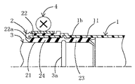
図2において、チューブ1の一端に、内筒部21と外筒部22を備えた弾性シール部材2が嵌着されている係合端部11に相手部材3を挿入した後、その外周をクランプ等の締結部材4で締め付けることにより、チューブと相手部材を流体密に接続したものである。チューブ1の構造は、(1)PA6,PA12,PA11からなる単層構造、(2)内層材がETFE、THV(TFE,HFP,VDFの共重合体)PBN、PBT、EVOH、PVDF等、及びこれらに導電性を付与したもの、及び鉄、ステンレス、アルミニウム等の金属箔、外層材がPA6,PA12,PA11、PE、PP等の樹脂からなる2層構造、あるいは(3)上記(2)の2層構造の中間に接着剤層を設けた3層構造、の内のいずれかである。
【0026】
以下、本発明のチューブの締結構造体を具体的に説明する。
チューブは、ブロー成形又はコルゲート成形したものであって、一端に弾性シール部材を装着可能な係合端部を備え、内周面に凹部、外周面に突部有する環状膨出部が形成されている。弾性シール部材は、相手部材を挿入させて嵌着可能になしたもので、前記係合端部の外周面に嵌着する外筒部と係合端部の内周面に嵌着する内筒部を備えている。内筒部は、その内周面に環状の嵌合凹部、外周面に環状の嵌合凸部有する環状膨出部を備え、環状膨出部を境に端面側に基部、反対側に延長部で形成されている。相手部材は、弾性シール部材へ挿入可能であり、一端に弾性シール部材の凹部に嵌合する環状突起部を備える金属製管状物である。締結部材としては、外筒部外周に環状締結され、金属製であるクランプ等が採用される。
【0027】
次に本発明の実施例を図面に基づいて詳しく説明する。本発明は、チューブ1の一端にパイプ等の相手部材3を接続するためのチューブの締結構造体であって、本発明の好ましい具体例を図1〜図4に基づいて説明する。図において、1がチューブであり、チューブ1は、図3に示すように、後述する相手部材3の挿入端部31の長さに適合した軸方向に延びる係合端部11を一端に備え、係合端部11は、その内周面13に端面から軸方向に距離を隔てた中間位置に環状凹部1bが施されている。好ましくは、この環状凹部1bに対応して外周面12に環状凸部1aがブロー成形により一体に形成されている。
【0028】
そして、このチューブ1の係合端部11に筒状の弾性シール部材2が一端面から挿入されて、所定の位置に軸方向に移動不能に装着されている。この弾性シール部材2は、図2、図4に示すように、チューブ1の内周面13に嵌着される外周面を持つ内筒部21と、内筒部21の一端側に係合端部11の端面を覆うと共に係合端部11の外周面12を覆うように外側に曲げ返されているキャップ状の外筒部22が一体に形成されている。
【0029】
内筒部21は、内周面には相手部材3の環状突起部3aが嵌まる環状の嵌合凹部2bが、また、外周面には図2に示すように、チューブ1の環状凹部1bに適合した環状の嵌合凸部2aが施され、この環状の嵌合凸部2aから、さらに軸方向内方に延びた延長部23と環状の嵌合凸部2aから軸方向外方に延びた基部24とで構成されている。
【0030】
延長部23の軸方向内端部は、図4に示すように、厚さ方向の中間位置にて分岐して、互いに径方向外方及び内方に向けてかつ軸線に対して所定角度傾斜して延びる環状の外分岐部23a及び内分岐部23bになっている。これにより、内筒部21は、外分岐部23aにおいて係合端部11と緊密に接触してシール性が良好に確保され、内分岐部23bにおいては相手部材3と緊密に接触してシール性が良好に確保される。
【0031】
そして、筒状の弾性シール部材2の内周面に相手部材3の挿入端部31が装着されている。この相手部材3は、図2に示すように、挿入端部31に弾性シール部材2の環状の嵌合凹部2bに適合する環状突起部3aが先端から距離を隔てた位置に施されている。
【0032】
つぎに、このように構成されたチューブの締結構造体の組立方法について説明する。先ず、チューブ1の係合端部11の端面側から筒状の弾性シール部材2を係合端部11が弾性シール部材の内筒部21と外筒部22との間に嵌め込むように挿入し、弾性シール部材2の環状の嵌合凸部2aをチューブ1に形成された環状凹部1bに嵌合させる。好ましくは、この時、係合端部11の外周を覆う外筒部22の折り返し端面22aがチューブ1の係合端部11の一端面に当接される。
【0033】
しかる後、弾性シール部材2の外筒部22外周に弛んだ締結部材4を装着し、外筒部22の折り返し端面22a側から管状の相手部材3を挿入し、相手部材3の環状突起部3aを弾性シール部材2の環状凹部2bに嵌合させ、締結部材4で締め付けを行うことによりチューブの締結構造体を構成することができる。
【0034】
また、好ましくは、弾性シール部材2の内筒部21の基部24の内径を相手部材3の挿入端部31の外径より大きくすることにより、挿入端部31の挿入を容易にすることができる。他方、内筒部21の延長部23の内径を挿入端部31の外径より小さくすることにより、弾性シール部材2と挿入端部31とのシール性を高めることができる。
【0035】
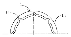
また、本実施例の変形態様1として、図5、6に示すチューブ1は、係合端部11の環状凹部1bと端面間が周方向に波形を有する波形筒状部14に形成されている以外は、図3に示す構造と同一である。このような波形筒状部14を形成することにより、相手部材3の挿入を容易にできる。また、波形筒状部14を設けたことにより、締結部材4が締結される部分において係合端部11においてしわの発生を吸収できるため、締結部分におけるシール性が確保され、流体洩れを防止できる。
【0036】
また、本実施例の変形態様2として、図7に示すチューブ1は、係合端部11の周方向の一ヶ所にて、係合端部11の一端面から環状凸部1aに向けて軸方向に延びるスリット15を設けており、その他は図3に示す構造と同一である。このようなスリット15を設けることにより、相手部材3の挿入を容易にできる。また、スリット15を設けたことにより、締結部材4が締結される部分においてスリットによりしわの発生を吸収できるため、締結部分におけるシール性が確保され、流体洩れを防止できる。また、スリット15の形成は、上記波形筒状部14の形成より容易である。なお、スリット15については、周方向の1個所に限らず、複数箇所に設けることもできる。
【0037】
また、本実施例の変形態様3として、図8に示す弾性シール部材2は、内筒部21の延長部23の外周面及び内周面にて軸方向の複数箇所に、径方向外方及び内方に向けて同軸的に突出した環状の突出シール部25を設けたものであり、その他は図4に示す構造と同一である。これにより、内筒部21は外方に突出した突出シール部25が、係合端部11と緊密に接触してシール性が良好に確保され、内方に突出した突出シール部25により相手部材3と緊密に接触してシール性が良好に確保される。
【0038】
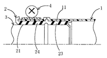
また、本実施例の変形態様4として、図9に示す弾性シール部材2は、上記実施形態において示した外筒部22が無い以外は、図4に示す構造と同一である。このように弾性シール部材2の外筒部22を無くすことにより、弾性シール部材2のチューブ1への挿入を容易にすることができる。
以上本発明の実施例を詳述したがこれらはあくまで一例示であり、本発明はその主旨を逸脱しない範囲において種々変更を加えた形態で構成可能である。
【図面の簡単な説明】
【図1】本発明のチューブ締結構造体の一実施例の下半分を省略した要部断面図である。
【図2】図1の締結方法を説明する、下半分を省略した要部断面図である。
【図3】図1に用いられるチューブの下半分を省略した要部断面図である。
【図4】図1に用いられる弾性シール部材の下半分を省略した断面図である。
【図5】本発明の他の実施例(変形態様1)を説明する斜視図である。
【図6】図5の左から見た下半分を省略した正面図である。
【図7】本発明の他の実施例(変形態様2)を説明する斜視図である。
【図8】本発明の他の実施例(変形態様3)を説明する下半分を省略した要部断面図である。
【図9】さらに、本発明の他の実施例(変形態様4)を説明する下半分を省略した要部断面図である。
【図10】従来技術の締結構造体を説明する要部断面図である。
【符号の説明】
1 チューブ
11 係合端部
12 外周面
13 内周面
14 波形筒状部
15 スリット
1a 環状凸部
1b 環状凹部
2 弾性シール部材
21 内筒部
22 外筒部
23 延長部
24 基部
25 突出シール部
2a 環状の嵌合凸部
2b 環状の嵌合凹部
3 相手部材
3a 環状突部
4 締結部材
5 金属チューブ
5a 溝
6 保護スリーブ
7 薄肉チューブ
8 金属製スリーブ[0001]
BACKGROUND OF THE INVENTION
The present invention relates to a tube fastening structure in which a tube and a flange-like mating member such as a rigid pipe made of resin and metal are fluid-tightly connected. For example, it is suitably used for a fastening structure of a tube and a metal pipe for automobiles that require gasoline resistance.
[0002]
[Prior art]
Conventionally, as this type of fastening structure, the one described in JP-A-4-171391 is known. That is, as shown in FIG. 10, the connection portion of the
[0003]
[Problems to be solved by the invention]
However, since the
[0004]
In view of such circumstances, the present invention provides a tube connector that can easily improve the sealing performance between a tube and a tubular mating member and that can be easily connected at any place such as an assembly site of an automobile. The first purpose.
[0005]
Another object of the present invention is to provide a tube connecting body that prevents fluid leakage due to wrinkles generated during tightening.
[0006]
[Means for Solving the Problems and Effects of the Invention]
In order to achieve the above object, a first structural feature of the present invention (corresponding to claim 1) is a tube fastening structure for connecting a mating member to one end of the tube. A tube extending to the end, an engagement end formed at one end of the tube having an annular recess formed on the inner circumferential surface at a distance from the one end surface in the axial direction, and inserted into the engagement end of the tube. An insertion end that can be inserted into the inner periphery of the elastic seal member and has a cylindrical elastic seal member that is attached, and an annular protrusion that protrudes axially outward from the outer peripheral surface at a distance from the tip. An inner cylinder having an outer peripheral surface fitted to an inner peripheral surface of the engaging end of the tube, and a tubular mating member provided with a portion and a fastening member arranged annularly on the outer periphery of the tube And one end surface of the engagement end portion on one end side of the inner cylinder portion and the outer periphery of the engagement end portion An outer tube portion bent outward to cover the surface, and an annular fitting convex portion adapted to the annular concave portion of the tube on the outer peripheral surface of the inner cylindrical portion and an annular shape of the mating member on the inner peripheral surface A fastening member is provided on the outer periphery of the outer cylindrical portion with an annular fitting recess into which the protrusion is fitted, and the insertion end of the mating member is inserted into the inner peripheral surface of the cylindrical elastic seal member. It is fastened and comprises a tube fastening structure characterized by comprising an annular convex portion protruding radially outward from the outer peripheral surface of the engaging end portion in the middle of the engaging end portion. is there.
[0007]
As described above, the present invention includes an engagement end portion having an annular recess formed at a position spaced in the axial direction from the one end surface, and the cylindrical elastic seal member is provided at the engagement end portion of the tube. An inner cylindrical portion having an outer peripheral surface inserted into the inner peripheral surface, and an outer cylindrical portion bent outward so as to cover the end surface of the engaging end portion on one end side of the inner cylindrical portion and to cover the outer peripheral surface of the engaging end portion with the door, and, since the fitting projection adapted to the annular recess of the tube to the outer peripheral surface and the inner peripheral surface of the inner cylindrical portion is annular protrusion of the mating member has a fitting recess for fitting, mating member Is held so as not to move in the axial direction with respect to the cylindrical elastic seal member. The cylindrical elastic seal member is held so as not to move in the axial direction with respect to the tube.
One end of the tube is sandwiched between the inner cylinder part and the outer cylinder part of the elastic seal member, and is fastened by a fastening member from the outer periphery of the outer cylinder part. Therefore, the counterpart member can be prevented from coming off the tube.
[0008]
Further, by providing an annular convex portion that protrudes radially outward from the outer peripheral surface of the engaging end portion in the middle of the engaging end portion, wrinkles generated at the engaging end portion during fastening are annular convex. Therefore, the sealing performance between the engagement end portion of the tube, the inner cylinder portion of the elastic seal member, and the insertion end portion of the mating member can be enhanced.
[0009]
According to a second structural feature of the present invention (corresponding to claim 2 ), in the first feature , the annular recess formed in the inner peripheral surface of the engagement end portion is an intermediate portion of the engagement end portion. A fastening member is disposed at one end side position from the annular convex portion, and the inner cylinder portion of the elastic seal member includes an extension portion extending inward in the axial direction from the annular fitting convex portion of the inner cylindrical portion. There is in being. Thus, since the inner cylinder part of the elastic seal member is provided with the extension part, the extension part is in a part away from the part to which the fastening member is fastened, so that the engagement end part is not affected by the fastening. Is surely sealed.
[0010]
According to a third structural feature of the present invention (corresponding to claim 3 ), in the first or second feature, the annular recess at the engagement end of the tube and the one end surface have a waveform in the circumferential direction. It exists in being formed in the corrugated cylindrical part which has. Thereby, since the generation of wrinkles can be absorbed by the corrugated tubular portion at the portion where the fastening member is fastened, the sealing performance at the fastening portion is ensured and fluid leakage can be reliably prevented.
[0011]
According to a fourth structural feature of the present invention (corresponding to claim 4 ), in the first or second feature, at least one point in the circumferential direction of the engagement end portion of the tube from one end surface. A slit extending in the direction of the annular recess is provided. Thereby, since generation | occurrence | production of a wrinkle can be absorbed by the slit in the part to which a fastening member is fastened, the sealing performance in a fastening part is ensured and fluid leakage can be prevented reliably. Moreover, it is easier to form the slit than the corrugated cylindrical portion.
[0012]
According to a fifth structural feature (corresponding to claim 5 ) of the present invention, in the first, second, third, or fourth feature, the inner end portion in the axial direction of the inner cylinder portion has a thickness. It is in the form of an annular outer branch portion and inner branch portion that branch at an intermediate position in the direction and extend while inclining radially outward and inward. As a result, the inner cylinder portion is in intimate contact with the engagement end portion at the outer branch portion to ensure good sealing performance, and the inner branch portion is in close contact with the mating member to ensure good sealing performance. .
[0013]
According to a sixth structural feature (corresponding to claim 6 ) of the present invention, in the first, second, third, fourth, or fifth feature, the inner tube portion is an annular fitting recess. A base extending axially outward from the extension and an extension extending axially inward from the fitting recess, the base having an inner diameter slightly larger than the outer diameter of the insertion end of the mating member, while the extension is of the mating member The inner diameter is slightly smaller than the outer diameter of the insertion end. Thereby, it is possible to facilitate the insertion of the insertion end portion into the base portion, while it is possible to improve the sealing performance between the elastic seal member and the insertion end portion in the extension portion.
[0014]
According to a seventh structural feature (corresponding to claim 7 ) of the present invention, in the first, second, third, fourth, fifth or sixth feature, An annular projecting seal portion projecting coaxially toward the radially outer side and the inner side is provided at a plurality of locations in the axial direction on the outer peripheral surface and the inner peripheral surface. As a result, the inner cylinder part comes into close contact with the engagement end part by the projecting seal part projecting outward, and a good sealing performance is ensured, and the projecting seal part projecting inward makes close contact with the mating member. As a result, good sealing performance is ensured.
[0015]
Further, an eighth structural feature of the present invention (corresponding to claim 8 ) is that the tube structure of the first, second, third, fourth, fifth, sixth or seventh feature is the same as that of the first, second, third, fourth, fifth, sixth or seventh feature. Either a single layer structure of resin, a two-layer structure in which the inner layer is a resin, a conductive resin or a metal film, and the outer layer is a resin, or a three-layer structure in which an adhesive layer is provided between the inner layer and the outer layer There is to be. Thereby, the structure of the tube can be variously selected according to the application.
[0016]
Further, a ninth structural feature of the present invention (corresponding to claim 9 ) is a tube fastening structure for connecting a mating member to one end of the tube, the tube extending from one end to the other end, An axially extending engagement end formed on one end of a tube having an annular recess formed at a position spaced axially from one end surface on the inner peripheral surface, and an engagement end of the tube An insertion that can be inserted into the inner periphery of the elastic seal member having an inserted cylindrical elastic seal member and an annular protrusion protruding axially outward from the outer peripheral surface at a distance from the tip. A tubular mating member having an end portion and a fastening member arranged in an annular shape on the outer periphery of the tube, and the elastic seal member covers only one end surface of the engaging end portion of the tube and the inner periphery of the engaging end portion An inner cylinder portion having an outer peripheral surface fitted to the surface, and an outer peripheral surface of the inner cylinder portion An annular fitting convex portion adapted to the annular concave portion of the tube and an annular fitting concave portion into which the annular protrusion of the mating member is fitted on the inner peripheral surface, and the insertion end of the mating member is a cylindrical elastic seal member The fastening member is fastened to the outer periphery of the engaging end portion in a state of being inserted into the inner peripheral surface of the engaging end portion, and protrudes radially outward from the outer peripheral surface of the engaging end portion in the middle of the engaging end portion. It is in having provided the annular convex part . According to the present invention, in the first configuration, the outer cylindrical portion of the elastic seal member is eliminated, and in addition to the effects of the first configuration, the elastic seal member can be easily inserted into the tube. be able to.
[0017]
Further, by providing an annular convex portion that protrudes radially outward from the outer peripheral surface of the engaging end portion in the middle of the engaging end portion, wrinkles generated at the engaging end portion during fastening are annular convex. Therefore, the sealing performance between the engagement end portion of the tube, the inner cylinder portion of the elastic seal member, and the insertion end portion of the mating member can be enhanced.
[0018]
According to a tenth structural feature of the present invention (corresponding to claim 10 ), in the ninth feature, the annular recess formed in the inner peripheral surface of the engaging end is an intermediate portion of the engaging end. A fastening member is disposed at one end side position from the annular convex portion, and the inner cylinder portion of the elastic seal member includes an extension portion extending inward in the axial direction from the annular fitting convex portion of the inner cylindrical portion. There is in being. Thus, since the inner cylinder part of the elastic seal member is provided with the extension part, the extension part is in a part away from the part to which the fastening member is fastened, so that the engagement end part is not affected by the fastening. Is surely sealed.
[0019]
Further, an eleventh structural feature of the present invention (corresponding to claim 11 ) is that in the ninth or tenth feature, the annular recess of the engagement end portion of the tube and the one end surface are corrugated in the circumferential direction. It exists in being formed in the corrugated cylindrical part which has. Thereby, since the generation of wrinkles can be absorbed by the corrugated tubular portion at the portion where the fastening member is fastened, the sealing performance at the fastening portion is ensured and fluid leakage can be reliably prevented.
[0020]
Further, a twelfth structural feature of the present invention (corresponding to claim 12 ) is that, in the ninth or tenth feature, at least one point in the circumferential direction of the engaging end portion of the tube from one end surface. A slit extending in the direction of the annular recess is provided. Thereby, since generation | occurrence | production of a wrinkle can be absorbed by the slit in the part to which a fastening member is fastened, the sealing performance in a fastening part is ensured and fluid leakage can be prevented reliably. Moreover, it is easy to form a slit at the engaging end.
[0021]
According to a thirteenth structural feature of the present invention (corresponding to claim 13 ), in the ninth, tenth, eleventh or twelfth feature, the axially inner end portion of the inner cylinder portion is thick. It is in the form of an annular outer branch portion and inner branch portion that branch at an intermediate position in the direction and extend while inclining radially outward and inward. As a result, the inner cylinder portion is in intimate contact with the engagement end portion at the outer branch portion to ensure good sealing performance, and the inner branch portion is in close contact with the mating member to ensure good sealing performance. .
[0022]
According to a fourteenth structural feature (corresponding to claim 14 ) of the present invention, in the ninth, tenth, eleventh, twelfth or thirteenth feature, the inner tube portion is an annular fitting recess. A base extending axially outward from the extension and an extension extending axially inward from the fitting recess, the base having an inner diameter slightly larger than the outer diameter of the insertion end of the mating member, while the extension is of the mating member The inner diameter is slightly smaller than the outer diameter of the insertion end. Thereby, the insertion of the insertion end portion into the base portion can be facilitated, and the sealing performance between the elastic seal member and the insertion end portion can be enhanced at the extension portion.
[0023]
According to a fifteenth structural feature (corresponding to claim 15 ) of the present invention, in the ninth, tenth, eleventh, twelfth, thirteenth, or fourteenth feature, An annular projecting seal portion projecting coaxially toward the radially outer side and the inner side is provided at a plurality of locations in the axial direction on the outer peripheral surface and the inner peripheral surface. As a result, the inner cylinder part comes into close contact with the engagement end part by the projecting seal part projecting outward, and a good sealing performance is ensured, and the projecting seal part projecting inward makes close contact with the mating member. As a result, good sealing performance is ensured.
[0024]
According to a sixteenth structural feature of the present invention (corresponding to claim 16 ), in the ninth, tenth, eleventh, twelfth, thirteenth, fourteenth, or fifteenth feature, the structure of the tube is Either a single layer structure of resin, a two-layer structure in which the inner layer is a resin, a conductive resin or a metal film, and the outer layer is a resin, or a three-layer structure in which an adhesive layer is provided between the inner layer and the outer layer There is to be. Thereby, the structure of the tube can be variously selected according to the application.
[0025]
DETAILED DESCRIPTION OF THE INVENTION
In FIG. 2, after inserting the
[0026]
Hereinafter, the tube fastening structure of the present invention will be described in detail.
The tube is blow-molded or corrugated, and has an engagement end portion to which an elastic seal member can be attached at one end, and an annular bulging portion having a recess on the inner peripheral surface and a protrusion on the outer peripheral surface is formed. Yes. The elastic seal member can be fitted by inserting a mating member, and an outer cylinder portion that fits on the outer peripheral surface of the engagement end portion and an inner cylinder that fits on the inner peripheral surface of the engagement end portion Department. The inner cylinder part includes an annular bulging part having an annular fitting concave part on the inner peripheral surface and an annular bulging convex part on the outer peripheral surface, and a base part on the end face side with the annular bulging part as a boundary and an extension part on the opposite side It is formed with. The mating member is a metal tubular object that can be inserted into the elastic seal member and has an annular protrusion that fits into one end of the recess of the elastic seal member. As the fastening member, a clamp or the like that is annularly fastened to the outer periphery of the outer cylinder portion and made of metal is employed.
[0027]
Next, embodiments of the present invention will be described in detail with reference to the drawings. The present invention is a tube fastening structure for connecting a
[0028]
A tubular
[0029]
The inner
[0030]
As shown in FIG. 4, the axially inner end of the
[0031]
The insertion end 31 of the
[0032]
Next, a method for assembling the tube fastening structure configured as described above will be described. First, the tubular
[0033]
Thereafter, the loosened
[0034]
Preferably, the insertion end 31 can be easily inserted by making the inner diameter of the
[0035]
Moreover, as a
[0036]
Further, as a modified
[0037]
Moreover, as a
[0038]
Moreover, as a
Although the embodiments of the present invention have been described in detail above, these are merely examples, and the present invention can be configured in various modifications without departing from the spirit of the present invention.
[Brief description of the drawings]
FIG. 1 is a cross-sectional view of a principal part in which a lower half of an embodiment of a tube fastening structure according to the present invention is omitted.
FIG. 2 is a cross-sectional view of a main part, with the lower half omitted, illustrating the fastening method of FIG. 1;
3 is a cross-sectional view of a main part in which a lower half of a tube used in FIG. 1 is omitted.
4 is a cross-sectional view in which the lower half of the elastic seal member used in FIG. 1 is omitted.
FIG. 5 is a perspective view for explaining another embodiment (deformation mode 1) of the present invention.
6 is a front view of the lower half of FIG. 5 as seen from the left.
FIG. 7 is a perspective view for explaining another embodiment (deformation mode 2) of the present invention.
FIG. 8 is a cross-sectional view of an essential part, omitting the lower half, illustrating another embodiment (deformation mode 3) of the present invention.
FIG. 9 is a cross-sectional view of an essential part, omitting the lower half, for explaining another embodiment (deformation mode 4) of the present invention.
FIG. 10 is a cross-sectional view of a main part for explaining a conventional fastening structure.
[Explanation of symbols]
DESCRIPTION OF
2
3
4 Fastening member
5 Metal tube 5a Groove
6 Protection sleeve
7 Thin-walled tube
8 Metal sleeve
Claims (16)
一端から他端に延びる該チューブと、
内周面に一端面から軸方向に距離を隔てた位置に形成された環状凹部を有する該チューブの該一端に形成された、軸方向に延びている係合端部と、
該チューブの該係合端部に挿着された筒状の弾性シール部材と、
先端から距離を隔てた位置に、その外周面から軸方向外方に突出した環状突起部を有し、該弾性シール部材の内周に挿入可能な挿入端部を備えた管状の相手部材と、
該チューブの外周に環状に配置された締結部材とを備え、
前記弾性シール部材は前記チューブの該係合端部の内周面に嵌着された外周面をもつ内筒部と、該内筒部一端側に該係合端部の前記一端面を覆うと共に該係合端部の外周面を覆うように外側に曲げ返されている外筒部とを備え、且つ、該内筒部の外周面に前記チューブの環状凹部に適合した環状の嵌合凸部と該内周面に前記相手部材の環状突起部が嵌合する環状の嵌合凹部を備え、
前記相手部材の挿入端部が、前記筒状の弾性シール部材の内周面に挿着された状態で、
前記外筒部の外周に、前記締結部材が締結されており、
前記係合端部の中間に、該係合端部の外周面から径方向外方に突出した環状凸部を備えていることを特徴とするチューブの締結構造体。A tube fastening structure for connecting a mating member to one end of the tube,
The tube extending from one end to the other;
An axially extending engagement end formed at the one end of the tube having an annular recess formed at a position spaced axially from the one end surface on the inner peripheral surface;
A cylindrical elastic seal member inserted into the engagement end of the tube;
A tubular mating member having an annular protrusion protruding axially outward from its outer peripheral surface at a position spaced from the tip, and having an insertion end that can be inserted into the inner periphery of the elastic seal member;
A fastening member arranged annularly on the outer periphery of the tube,
The elastic seal member covers an inner cylinder portion having an outer peripheral surface fitted to an inner peripheral surface of the engagement end portion of the tube, and covers the one end surface of the engagement end portion on one end side of the inner cylinder portion. An outer tube portion bent outward so as to cover the outer peripheral surface of the engagement end portion, and an annular fitting convex portion adapted to the annular concave portion of the tube on the outer peripheral surface of the inner cylinder portion And an annular fitting recess into which the annular protrusion of the mating member is fitted on the inner peripheral surface,
With the insertion end of the mating member being inserted into the inner peripheral surface of the cylindrical elastic seal member,
The outer periphery of the outer cylindrical portion, the fastening member is fastened,
A tube fastening structure comprising an annular convex portion projecting radially outward from an outer peripheral surface of the engagement end portion in the middle of the engagement end portion .
一端から他端に延びる該チューブと、
内周面に一端面から軸方向に距離を隔てた位置に形成された環状凹部を有する該チューブの該一端に形成された、軸方向に延びている係合端部と、
該チューブの該係合端部に挿着された筒状の弾性シール部材と、
先端から距離を隔てた位置に、その外周面から軸方向外方に突出した環状突起部を有し、該弾性シール部材の内周に挿入可能な挿入端部を備えた管状の相手部材と、
該チューブの外周に環状に配置された締結部材とを備え、
前記弾性シール部材は前記チューブの該係合端部の前記一端面のみを覆うと共に該係合端部の内周面に嵌着された外周面をもつ内筒部を備え、且つ、該内筒部の外周面に前記チューブの環状凹部に適合した環状の嵌合凸部と該内周面に前記相手部材の環状突起部が嵌合する環状の嵌合凹部を備え、
前記相手部材の挿入端部が、前記筒状の弾性シール部材の内周面に挿着された状態で、
前記係合端部の外周に、前記締結部材が締結されており、
前記係合端部の中間に、該係合端部の外周面から径方向外方に突出した環状凸部を備えていることを特徴とするチューブの締結構造体。 A tube fastening structure for connecting a mating member to one end of the tube ,
The tube extending from one end to the other ;
An axially extending engagement end formed at the one end of the tube having an annular recess formed at a position spaced axially from the one end surface on the inner peripheral surface ;
A cylindrical elastic seal member inserted into the engagement end of the tube ;
A tubular mating member having an annular protrusion protruding axially outward from its outer peripheral surface at a position spaced from the tip, and having an insertion end that can be inserted into the inner periphery of the elastic seal member ;
A fastening member arranged annularly on the outer periphery of the tube ,
The elastic seal member includes an inner cylinder portion that covers only the one end surface of the engagement end portion of the tube and has an outer peripheral surface fitted on an inner peripheral surface of the engagement end portion, and the inner cylinder An annular fitting convex portion adapted to the annular concave portion of the tube on the outer peripheral surface of the portion and an annular fitting concave portion into which the annular projection portion of the mating member is fitted to the inner peripheral surface ;
With the insertion end of the mating member being inserted into the inner peripheral surface of the cylindrical elastic seal member ,
The fastening member is fastened to the outer periphery of the engagement end,
A tube fastening structure comprising an annular convex portion projecting radially outward from an outer peripheral surface of the engagement end portion in the middle of the engagement end portion .
Priority Applications (3)
| Application Number | Priority Date | Filing Date | Title |
|---|---|---|---|
| JP2000140833A JP3899780B2 (en) | 1999-05-27 | 2000-05-12 | Tube fastening structure |
| EP00304513A EP1055859B1 (en) | 1999-05-27 | 2000-05-26 | Tube clamping structure |
| US09/578,449 US6478341B1 (en) | 1999-05-27 | 2000-05-26 | Tube clamping structure |
Applications Claiming Priority (3)
| Application Number | Priority Date | Filing Date | Title |
|---|---|---|---|
| JP14804099 | 1999-05-27 | ||
| JP11-148040 | 1999-05-27 | ||
| JP2000140833A JP3899780B2 (en) | 1999-05-27 | 2000-05-12 | Tube fastening structure |
Publications (2)
| Publication Number | Publication Date |
|---|---|
| JP2001041379A JP2001041379A (en) | 2001-02-13 |
| JP3899780B2 true JP3899780B2 (en) | 2007-03-28 |
Family
ID=26478400
Family Applications (1)
| Application Number | Title | Priority Date | Filing Date |
|---|---|---|---|
| JP2000140833A Expired - Fee Related JP3899780B2 (en) | 1999-05-27 | 2000-05-12 | Tube fastening structure |
Country Status (3)
| Country | Link |
|---|---|
| US (1) | US6478341B1 (en) |
| EP (1) | EP1055859B1 (en) |
| JP (1) | JP3899780B2 (en) |
Families Citing this family (18)
| Publication number | Priority date | Publication date | Assignee | Title |
|---|---|---|---|---|
| GB2373303B (en) * | 2001-01-23 | 2004-07-21 | Smiths Group Plc | A pipe coupling having inner and outer layers of deformable material |
| JP4128079B2 (en) | 2001-02-06 | 2008-07-30 | スウエイジロク・カンパニー | Pipe fittings for stainless steel pipes |
| US7407196B2 (en) | 2003-08-06 | 2008-08-05 | Swagelok Company | Tube fitting with separable tube gripping device |
| US7416225B2 (en) | 2001-02-06 | 2008-08-26 | Swagelok Company | Fitting for metal pipe and tubing |
| US7784837B2 (en) | 2003-11-03 | 2010-08-31 | Swagelok Company | Fitting for metal pipe and tubing |
| US7150365B2 (en) * | 2004-02-03 | 2006-12-19 | Rtc Industries, Inc. | Product securement and management system |
| TW200602577A (en) | 2004-04-22 | 2006-01-16 | Swagelok Co | Fitting for tube and pipe |
| US7497483B2 (en) | 2004-04-22 | 2009-03-03 | Swagelok Company | Fitting for tube and pipe with cartridge |
| US7431344B2 (en) * | 2005-08-16 | 2008-10-07 | Cascade Engineering, Inc. | Connection assembly and related method |
| US10215315B2 (en) | 2008-09-05 | 2019-02-26 | Parker-Hannifin Corporation | Tube compression fitting and flared fitting used with connection body and method of making same |
| GB2521479A (en) * | 2013-12-20 | 2015-06-24 | Gm Global Tech Operations Inc | Joining means and method for joining at least two piping elements |
| KR102398921B1 (en) | 2014-05-09 | 2022-05-16 | 스와겔로크 컴패니 | Conduit fitting with components adapted for facilitating assembly |
| CN105042074A (en) * | 2015-06-27 | 2015-11-11 | 奇瑞商用车(安徽)有限公司 | Sealing connecting structure and method for plastic oil filling pipe and fuel tank |
| US10584814B2 (en) | 2016-03-23 | 2020-03-10 | Swagelok Company | Conduit fitting with stroke resisting features |
| JP2017172745A (en) * | 2016-03-25 | 2017-09-28 | 住友電装株式会社 | Grommet fitting structure and grommet |
| US10794524B2 (en) | 2016-09-06 | 2020-10-06 | Keith R. Bunn, SR. | Pipe coupling assembly |
| JP6763346B2 (en) * | 2017-01-23 | 2020-09-30 | 株式会社オートネットワーク技術研究所 | Electromagnetic shield parts and wire harness |
| US11994242B2 (en) * | 2021-10-08 | 2024-05-28 | Little Chief Industries, Inc. | Coupling seal for pipe liners |
Family Cites Families (13)
| Publication number | Priority date | Publication date | Assignee | Title |
|---|---|---|---|---|
| DE369924C (en) * | 1923-02-24 | Rudolf Hoeing | Socket connection for pipes | |
| US3633947A (en) * | 1970-02-20 | 1972-01-11 | Corning Glass Works | Coupling |
| GB1432471A (en) * | 1973-05-14 | 1976-04-14 | Broomhead F | Flexible pipe joints and sealing rings therefor |
| CH664814A5 (en) * | 1984-09-17 | 1988-03-31 | Von Roll Ag | SLEEVE CONNECTION. |
| GB2245944B (en) * | 1990-07-09 | 1993-12-15 | Thermopol Limited | Hose and hollow member arrangements |
| JP2677009B2 (en) | 1990-11-01 | 1997-11-17 | 富士電機株式会社 | Connection structure between thin-walled tube and metal tube |
| JPH06221481A (en) | 1993-01-22 | 1994-08-09 | Toyoda Gosei Co Ltd | Hose |
| JPH06307583A (en) | 1993-04-23 | 1994-11-01 | Toyoda Gosei Co Ltd | Hose |
| JP2850700B2 (en) | 1993-04-27 | 1999-01-27 | 豊田合成株式会社 | hose |
| JPH06307585A (en) | 1993-04-27 | 1994-11-01 | Toyoda Gosei Co Ltd | Hose |
| DE69412988T2 (en) * | 1993-06-14 | 1999-03-25 | Tokai Rubber Industries, Ltd., Komaki, Aichi | HOSE WITH PROTECTION |
| JP3683006B2 (en) | 1995-04-26 | 2005-08-17 | 丸五ゴム工業株式会社 | Fuel hose |
| JP3690053B2 (en) | 1997-03-29 | 2005-08-31 | 東海ゴム工業株式会社 | Resin-rubber composite hose and connection structure of this hose and mating pipe |
-
2000
- 2000-05-12 JP JP2000140833A patent/JP3899780B2/en not_active Expired - Fee Related
- 2000-05-26 US US09/578,449 patent/US6478341B1/en not_active Expired - Fee Related
- 2000-05-26 EP EP00304513A patent/EP1055859B1/en not_active Expired - Lifetime
Also Published As
| Publication number | Publication date |
|---|---|
| JP2001041379A (en) | 2001-02-13 |
| EP1055859A2 (en) | 2000-11-29 |
| EP1055859A3 (en) | 2003-01-08 |
| US6478341B1 (en) | 2002-11-12 |
| EP1055859B1 (en) | 2004-07-28 |
Similar Documents
| Publication | Publication Date | Title |
|---|---|---|
| JP3899780B2 (en) | Tube fastening structure | |
| US5871240A (en) | Hose with a protector | |
| EP1180633B1 (en) | Fuel hose connection structure and fuel hose | |
| JP3431630B2 (en) | Hose with protector | |
| JP3733848B2 (en) | Fuel hose connection structure and fuel hose | |
| JP3568067B2 (en) | Tube connection structure | |
| JP2850700B2 (en) | hose | |
| JP3690053B2 (en) | Resin-rubber composite hose and connection structure of this hose and mating pipe | |
| JP3451692B2 (en) | Low permeability hose and connection structure between low permeability hose and mating member | |
| JP3717225B2 (en) | Tube connection structure | |
| JP2002071065A (en) | Method for joining pressure resistant pipe | |
| JP2003176881A (en) | Hose with protector | |
| JPH0893976A (en) | Tube fitting device | |
| JP3767354B2 (en) | Fuel hose connection structure and fuel hose | |
| JP4448985B2 (en) | Seal connection structure of rigid mating pipe / hose and resin hose | |
| JPH0229351Y2 (en) | ||
| JPH0234538Y2 (en) | ||
| JPH07301379A (en) | Flexible pipe joint | |
| JPH06307585A (en) | Hose | |
| JPH0532714Y2 (en) | ||
| JPH0135999Y2 (en) | ||
| JP3653328B2 (en) | Tube connection structure | |
| JP2003120866A (en) | Hose with protector | |
| JPH08312844A (en) | Composite hose | |
| JPH0538489U (en) | Hose fittings |
Legal Events
| Date | Code | Title | Description |
|---|---|---|---|
| A621 | Written request for application examination |
Free format text: JAPANESE INTERMEDIATE CODE: A621 Effective date: 20040127 |
|
| A977 | Report on retrieval |
Free format text: JAPANESE INTERMEDIATE CODE: A971007 Effective date: 20051201 |
|
| A131 | Notification of reasons for refusal |
Free format text: JAPANESE INTERMEDIATE CODE: A131 Effective date: 20060214 |
|
| A521 | Written amendment |
Free format text: JAPANESE INTERMEDIATE CODE: A523 Effective date: 20060417 |
|
| TRDD | Decision of grant or rejection written | ||
| A01 | Written decision to grant a patent or to grant a registration (utility model) |
Free format text: JAPANESE INTERMEDIATE CODE: A01 Effective date: 20061205 |
|
| A61 | First payment of annual fees (during grant procedure) |
Free format text: JAPANESE INTERMEDIATE CODE: A61 Effective date: 20061218 |
|
| R150 | Certificate of patent or registration of utility model |
Free format text: JAPANESE INTERMEDIATE CODE: R150 |
|
| FPAY | Renewal fee payment (event date is renewal date of database) |
Free format text: PAYMENT UNTIL: 20110112 Year of fee payment: 4 |
|
| FPAY | Renewal fee payment (event date is renewal date of database) |
Free format text: PAYMENT UNTIL: 20120112 Year of fee payment: 5 |
|
| FPAY | Renewal fee payment (event date is renewal date of database) |
Free format text: PAYMENT UNTIL: 20130112 Year of fee payment: 6 |
|
| LAPS | Cancellation because of no payment of annual fees |