JP3898695B2 - 高圧流体発生装置 - Google Patents
高圧流体発生装置 Download PDFInfo
- Publication number
- JP3898695B2 JP3898695B2 JP2004009088A JP2004009088A JP3898695B2 JP 3898695 B2 JP3898695 B2 JP 3898695B2 JP 2004009088 A JP2004009088 A JP 2004009088A JP 2004009088 A JP2004009088 A JP 2004009088A JP 3898695 B2 JP3898695 B2 JP 3898695B2
- Authority
- JP
- Japan
- Prior art keywords
- pilot
- supply
- rod
- piston
- chamber
- Prior art date
- Legal status (The legal status is an assumption and is not a legal conclusion. Google has not performed a legal analysis and makes no representation as to the accuracy of the status listed.)
- Expired - Lifetime
Links
- 239000012530 fluid Substances 0.000 title claims description 32
- 238000012856 packing Methods 0.000 claims description 5
- 238000003825 pressing Methods 0.000 claims description 2
- 238000000034 method Methods 0.000 description 3
- 230000008602 contraction Effects 0.000 description 2
- 230000007423 decrease Effects 0.000 description 2
- 238000007599 discharging Methods 0.000 description 2
- 238000007667 floating Methods 0.000 description 2
- 238000007789 sealing Methods 0.000 description 2
- 238000004891 communication Methods 0.000 description 1
- 238000010276 construction Methods 0.000 description 1
- 238000004519 manufacturing process Methods 0.000 description 1
- 230000002093 peripheral effect Effects 0.000 description 1
Images


Landscapes
- Reciprocating Pumps (AREA)
- Fluid-Pressure Circuits (AREA)
Description
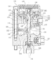
102 シリンダ
104 ピストン
106 給排弁部
108 プランジャ式ポンプ
110 圧力室
114 復帰ばね
122 給気路
124 排気路
126 給排気路
128 給排弁体
130 第1パイロット室
132 第2パイロット室
134 パイロット給気弁
136 パイロット排気弁
142 第1弁部
144 第2弁部
146 第1弁座
148 第2弁座
154 内孔
156 パイロットロッド
158 受け部
Claims (4)
- シリンダ内にピストンを設け、このシリンダ内における前記ピストンの一方の側に復帰バネを設け、他方の側を圧力室として、圧縮空気を給排弁を介して前記圧力室に給排することによって前記ピストンが往復動作し、その往復動作によってプランジャ式ポンプを駆動して、高圧流体を発生する装置であって、
前記給排弁が、前記シリンダが設けられている本体内に、圧縮空気源に接続される給気路と、外界に連通する排気路と、前記圧力室に連通する給排気路と、前記ピストンの移動方向に沿って移動可能である給排弁体とを、有し、
前記給排弁体は、第1及び第2弁部を有し、前記給排気路と前記給気路とを第2弁部で接続し、かつ前記給排気路と前記排気路とを第1弁部で遮断した給気位置と、前記給排気路と前記給気路とを第2弁部で遮断し、かつ前記給排気路と前記排気路とを第1弁部で接続した排気位置とに、切換可能であり、
前記給排弁体の移動方向の一端に第1パイロット室を設け、他端に前記給気路に連通した第2パイロット室を設け、
第1及び第2パイロット室を連通する内孔が、前記給排弁体内を前記ピストンの移動方向に貫通し、
前記ピストンと連動するように前記本体内に設けられたパイロットロッドを、前記内孔に挿通し、第2パイロット室と前記内孔との間を開閉するように前記パイロットロッドに給気弁部を形成し、
前記パイロットロッドの先端による押圧によって開弁されて、第1パイロット室を前記排気路に接続するパイロット排気弁を設け、
前記給排弁体の第1パイロット室側のパイロット圧受圧面積を第2パイロット室側のパイロット圧受圧面積よりも大きく形成した
高圧流体発生装置において、
前記パイロットロッドは、前記内孔、第2パイロット室及び前記圧力室を通って前記ピストンに基端が結合され、前記パイロットロッドが前記ピストンの移動方向に移動可能に、前記パイロットロッドの基端は、前記ピストンに設けたロッド受け部に遊嵌され、前記パイロットロッドの前記内孔側における受圧面積を、前記圧力室側における受圧面積よりも大きく形成した高圧流体発生装置。 - 請求項1記載の高圧流体発生装置において、前記パイロットロッドに設けた前記吸気弁部は、前記給気位置において前記内孔内に位置する前記パイロットロッドの部分に形成した一定の溝幅を有するパッキン溝にパッキンを収容したものである高圧流体発生装置。
- 請求項1記載の高圧流体発生装置において、前記ロッド受け部は、前記ピストンの前記一方の側に設けられた前記プランジャ式ポンプ駆動用ロッドに設けられ、前記パイロットロッドは、前記ピストンを貫通して、前記ロッド受け部に収容されている高圧流体発生装置。
- 請求項1記載の高圧流体発生装置において、前記給気位置において前記パイロットロッドの前記圧力室に位置する部分から前記基端までが、残りの部分よりも小径に形成されている高圧流体発生装置。
Priority Applications (1)
| Application Number | Priority Date | Filing Date | Title |
|---|---|---|---|
| JP2004009088A JP3898695B2 (ja) | 2004-01-16 | 2004-01-16 | 高圧流体発生装置 |
Applications Claiming Priority (1)
| Application Number | Priority Date | Filing Date | Title |
|---|---|---|---|
| JP2004009088A JP3898695B2 (ja) | 2004-01-16 | 2004-01-16 | 高圧流体発生装置 |
Publications (2)
| Publication Number | Publication Date |
|---|---|
| JP2005201164A JP2005201164A (ja) | 2005-07-28 |
| JP3898695B2 true JP3898695B2 (ja) | 2007-03-28 |
Family
ID=34822233
Family Applications (1)
| Application Number | Title | Priority Date | Filing Date |
|---|---|---|---|
| JP2004009088A Expired - Lifetime JP3898695B2 (ja) | 2004-01-16 | 2004-01-16 | 高圧流体発生装置 |
Country Status (1)
| Country | Link |
|---|---|
| JP (1) | JP3898695B2 (ja) |
Cited By (1)
| Publication number | Priority date | Publication date | Assignee | Title |
|---|---|---|---|---|
| WO2021029236A1 (ja) * | 2019-08-09 | 2021-02-18 | 株式会社コスメック | 発動機およびその発動機を備える油圧ポンプ装置 |
Families Citing this family (1)
| Publication number | Priority date | Publication date | Assignee | Title |
|---|---|---|---|---|
| JP5969318B2 (ja) | 2012-08-28 | 2016-08-17 | パスカルエンジニアリング株式会社 | 加圧エア駆動式ピストン往復動型油圧ポンプ |
-
2004
- 2004-01-16 JP JP2004009088A patent/JP3898695B2/ja not_active Expired - Lifetime
Cited By (2)
| Publication number | Priority date | Publication date | Assignee | Title |
|---|---|---|---|---|
| WO2021029236A1 (ja) * | 2019-08-09 | 2021-02-18 | 株式会社コスメック | 発動機およびその発動機を備える油圧ポンプ装置 |
| JP7426122B2 (ja) | 2019-08-09 | 2024-02-01 | 株式会社コスメック | 発動機およびその発動機を備える油圧ポンプ装置 |
Also Published As
| Publication number | Publication date |
|---|---|
| JP2005201164A (ja) | 2005-07-28 |
Similar Documents
| Publication | Publication Date | Title |
|---|---|---|
| US9764456B2 (en) | Pneumatic nail gun | |
| JP5969318B2 (ja) | 加圧エア駆動式ピストン往復動型油圧ポンプ | |
| CA2548404A1 (en) | Impact tool | |
| KR950002979B1 (ko) | 유체압 피스톤 발동기 | |
| JP2014233770A (ja) | 打込機 | |
| JP3898695B2 (ja) | 高圧流体発生装置 | |
| JP5245667B2 (ja) | 打込機 | |
| US6183217B1 (en) | Pilot control valve for controlling a reciprocating pump | |
| JP4428671B2 (ja) | 流体圧発生装置 | |
| JPH03229004A (ja) | 流体圧ピストン発動機 | |
| JP6796291B2 (ja) | エアシリンダ | |
| CN114270034B (zh) | 发动机及具备该发动机的液压泵装置 | |
| US20160327069A1 (en) | Flow passage unit and switching valve | |
| JP4165295B2 (ja) | 開閉弁及び開閉弁を有する打込機 | |
| JP3342929B2 (ja) | 高圧流体発生装置 | |
| US5328339A (en) | Pump driven by air pressure | |
| WO2020218545A1 (ja) | 空気圧工具 | |
| JP7496102B2 (ja) | 発動機およびその発動機を備える油圧ポンプ装置 | |
| JP2676111B2 (ja) | 流体圧駆動連続作動型往復動アクチュエータ | |
| KR102852603B1 (ko) | 수축 완충이 가능한 양방향 앵글 밸브 | |
| JPS5847262Y2 (ja) | 空圧−油圧変換機における切換弁装置 | |
| JP2016221618A (ja) | 打込機 | |
| JP2018185035A (ja) | 液圧シリンダ装置 | |
| JP2676110B2 (ja) | 流体圧駆動連続作動型往復動アクチュエータ | |
| JPH0749041Y2 (ja) | 流体圧駆動連続作動型往復動アクチュエータ |
Legal Events
| Date | Code | Title | Description |
|---|---|---|---|
| A977 | Report on retrieval |
Free format text: JAPANESE INTERMEDIATE CODE: A971007 Effective date: 20060914 |
|
| A131 | Notification of reasons for refusal |
Free format text: JAPANESE INTERMEDIATE CODE: A131 Effective date: 20060926 |
|
| A521 | Request for written amendment filed |
Free format text: JAPANESE INTERMEDIATE CODE: A523 Effective date: 20061122 |
|
| TRDD | Decision of grant or rejection written | ||
| A01 | Written decision to grant a patent or to grant a registration (utility model) |
Free format text: JAPANESE INTERMEDIATE CODE: A01 Effective date: 20061219 |
|
| A61 | First payment of annual fees (during grant procedure) |
Free format text: JAPANESE INTERMEDIATE CODE: A61 Effective date: 20061221 |
|
| R150 | Certificate of patent or registration of utility model |
Ref document number: 3898695 Country of ref document: JP Free format text: JAPANESE INTERMEDIATE CODE: R150 Free format text: JAPANESE INTERMEDIATE CODE: R150 |
|
| FPAY | Renewal fee payment (event date is renewal date of database) |
Free format text: PAYMENT UNTIL: 20100105 Year of fee payment: 3 |
|
| FPAY | Renewal fee payment (event date is renewal date of database) |
Free format text: PAYMENT UNTIL: 20130105 Year of fee payment: 6 |
|
| R250 | Receipt of annual fees |
Free format text: JAPANESE INTERMEDIATE CODE: R250 |
|
| FPAY | Renewal fee payment (event date is renewal date of database) |
Free format text: PAYMENT UNTIL: 20160105 Year of fee payment: 9 |
|
| R250 | Receipt of annual fees |
Free format text: JAPANESE INTERMEDIATE CODE: R250 |
|
| R250 | Receipt of annual fees |
Free format text: JAPANESE INTERMEDIATE CODE: R250 |
|
| R250 | Receipt of annual fees |
Free format text: JAPANESE INTERMEDIATE CODE: R250 |
|
| EXPY | Cancellation because of completion of term |