JP3897397B2 - Injection speed control device for injection molding machine - Google Patents
Injection speed control device for injection molding machine Download PDFInfo
- Publication number
- JP3897397B2 JP3897397B2 JP13228397A JP13228397A JP3897397B2 JP 3897397 B2 JP3897397 B2 JP 3897397B2 JP 13228397 A JP13228397 A JP 13228397A JP 13228397 A JP13228397 A JP 13228397A JP 3897397 B2 JP3897397 B2 JP 3897397B2
- Authority
- JP
- Japan
- Prior art keywords
- pressure
- injection
- mold
- injection speed
- resin pressure
- Prior art date
- Legal status (The legal status is an assumption and is not a legal conclusion. Google has not performed a legal analysis and makes no representation as to the accuracy of the status listed.)
- Expired - Fee Related
Links
Images

Landscapes
- Injection Moulding Of Plastics Or The Like (AREA)
Description
【発明の実施の形態】
【発明の属する技術分野】
この発明は、溶融材料をスクリューを移動させて射出成形型内に射出する射出成形機において使用され、溶融材料の射出速度を制御する射出速度制御装置に関係している。
【従来の技術】
従来、新たな射出成形型を使用して射出成形機により射出成形加工を行う場合には、新たな射出成形型から充分な品質を備えた製品を生み出す為にまず最初に何回か試し打ちをして新たな射出成形型に適した射出速度(即ち溶融材料射出圧)の制御条件を設定しなければならない。
従来このような新たな射出成形型に適した射出速度(即ち溶融材料射出圧)の制御条件の設定は、熟練した作業員が溶融樹脂の種類や射出成形型内の型凹所の大きさや形状等を考慮して勘と経験で行っていた。
しかしながら、熟練した作業員ではなくとも比較的容易に自動的に射出速度 (即ち溶融材料射出圧)の制御条件の設定を行う方法が特開平7−186231号公報に開示されている。ここにおいては、射出速度の制御条件を設定する時にはまず最初に、射出成形機から射出成形型内の型凹所に射出される溶融材料(通常は溶融樹脂)の一定射出速度を手動で射出成形機の射出速度制御装置に仮りに設定する。また、射出成形加工中の基準となる基準樹脂圧力もまた射出速度制御装置に設定する。そしてこの仮りの一定射出速度や基準樹脂圧力は、射出成形機の製造業者や販売業者や使用者により溶融樹脂の種類や射出成形型内の型凹所の大きさや形状等を基礎にして作成されているデータから選択することが出来る。
次に射出成形加工を開始し、射出成形加工の開始とともに射出成形型内の型凹所に射出され充填される溶融樹脂の圧力の検出も開始する。射出成形加工中に溶融樹脂の検出圧力が基準樹脂圧力よりも大きくなると、予め定められていた所定の減速率を溶融樹脂の検出圧力が基準樹脂圧力よりも大きくなった時点の射出速度に乗じて修正された射出速度を設定し、この修正された射出速度に従って射出成型加工が継続される。なおこの所定の減速率も、射出成形機の製造業者や販売業者や使用者により溶融樹脂の種類や射出成形型内の型凹所の大きさや形状等を基礎にして作成されているデータから選択することが出来る。
そして、このような射出速度の修正は射出成形加工中に溶融樹脂の検出圧力が基準樹脂圧力よりも大きくなっている間は所定の周期で繰り返し行われる。溶融樹脂の検出圧力が基準樹脂圧力よりも小さくなると、溶融樹脂の検出圧力が基準樹脂圧力よりも小さくなった時点で採用されていた修正された射出速度がそのまま維持される。
【発明が解決しようとする課題】
上述した如き従来の射出成形機の射出速度制御装置においては、基準樹脂圧力よりも大きくなった時点での溶融樹脂の検出圧力の圧力上昇速度(即ち圧力上昇率)とは無関係に上述した減速率が一定であることが下に記す幾つかの問題を生じさせている。
例えば、上記圧力上昇率が比較的小さく上述した一定の減速率が上記圧力上昇率に比べて大きな場合には、射出速度制御装置を使用して上述した如く溶融材料の検出圧力が上記基準圧力を越えている範囲において検出圧力と基準圧力との差異を無くす射出速度の修正値を演算して求める場合には、射出速度の修正により実際に溶融材料に圧力低下が生じるまでに時間が掛り実際の検出圧力が上記基準圧力に到達するまでの間に射出速度の修正がどんどん行われる為に、ついには射出速度が極めて零に接近し、溶融材料の流速を極めて零にさせてしまうことがある。これもまた、射出成形加工により成形される成形品にひけや流線などの成形不良を生じさせてしまう。
また上記圧力上昇率が比較的大きく上述した一定の減速率が上記圧力上昇率に比べて小さな場合には、より低い射出速度に修正されたにもかかわらず溶融材料に圧力低下が生ぜず、実際の検出圧力が上記基準圧力を大幅に越えて、ついには射出成形型の破損に至ることもある。
このために、上述した如き従来の射出成形機の射出速度制御装置においては、新たな射出成形型に適した射出速度(即ち溶融樹脂射出圧)の制御条件を設定出来るまでに必要な試し打ちの回数を熟練した作業員ではないとなかなか減少させることが出来なった。
この発明は上記事情の下でなされ、この発明の目的は、基準圧力よりも大きくなった溶融材料の検出圧力の圧力上昇率に対応して修正された射出速度を得ることが出来、ひいては修正された射出速度により達成される検出圧力が基準圧力から振れる量を小さくすることが出来て、新たな射出成形型に最適な射出速度の制御条件を熟練した作業員ではなくとも容易に短時間で得ることが出来る、射出成形機の射出速度制御装置を提供することである。
【課題を解決するための手段】
上述したこの発明の目的を解決する為に、この発明に従った射出成形機の射出充填速度制御装置は:溶融材料をスクリューを移動させて射出成形型内に射出し充填する射出成形機において使用され;スクリューの移動中に溶融材料の圧力を検出し、溶融材料の検出圧力を予め設定されている基準圧力と比較し、上記検出圧力が上記基準圧力を越えている範囲において上記検出圧力と上記基準圧力との差異を無くす射出速度の修正値を演算して求め;上記演算においては、上記検出圧力と上記基準圧力との偏差量を求め、この偏差量と上記検出圧力が上記基準圧力を越えた時点の射出速度とからPI(比例積分)演算またはPID(比例積分微分)演算により上記射出速度の修正値を求める;ことを特徴としている。
このような構成においては、スクリューの移動中に検出された溶融材料の圧力と予め設定されている基準圧力との差異を無くす射出速度の修正値を演算して求める場合に、上記演算において、上記検出圧力と上記基準圧力との偏差量を求め、この偏差量と上記検出圧力が上記基準圧力を越えた時点の射出速度とからPI(比例積分)演算またはPID(比例積分微分)演算により上記射出速度の修正値を求めるので、基準圧力よりも大きくなった溶融材料の検出圧力の圧力上昇率に対応して修正された射出速度を得ることが出来、ひいては修正された射出速度により達成される検出圧力が基準圧力から振れる量を小さくすることが出来る。
また前述した特開平7−186231号公報の従来例の如く射出速度を一定とした時に溶融材料の検出圧力は略比例して大きくなる傾向にあり、PI(比例積分)演算またはPID(比例積分微分)演算による射出速度の修正値の設定は、上記検出圧力が上記基準圧力を越えている範囲において閉ループ制御により行われ上記検出圧力が上記基準圧力以下になった時には行われないので、基準圧力に対する検出圧力のオーバーシュートやハンチング現象を防止することが出来る。
【発明の実施の形態】
以下、この発明の1つの実施の形態に従った、射出成形機の射出速度制御装置を添付の図面を参照しながら詳細に説明する。
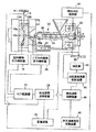
図1は、この発明の1つの実施の形態に従った射出成形機の射出速度制御装置の構成を概略的に示す図である。
夫々の対向表面に型凹所10a,10bが形成されている相互に接合及び離間自在な2つのブロック12A,12Bを所定の圧力で接合させている射出成形型14には、射出成形型14の2つのブロック12A,12B内の型凹所10a,10b中に後述する射出成形機から射出された溶融材料(この実施の形態では溶融樹脂)の圧力により射出成形型14の2つのブロック12A,12Bが開く量を検知する型開量検知器16と、型凹所10a,10b中で型凹所10a,10bに射出され充填された溶融樹脂の圧力を検出する型内溶融材料圧力検知器(この実施の形態では型内樹脂圧力検知器18)と、が設置されている。
この実施の形態において型開量検知器16は検知した型開量をデジタル信号として発信しており、射出速度演算装置38に接続されている。また型内樹脂圧力検知器18は検知した型内樹脂圧力をアナログ信号として発信しており、アナログ/デジタル変換器20を介して射出速度演算装置38に接続されている。
射出成形型14には型凹所10a,10bの溶融樹脂注入孔10cに対して接合及び離間自在な射出成形機22が油圧式移動装置24を介して連結されている。射出成形機22の加熱シリンダ26の射出ノズル26aには射出ノズル26aを介して射出成形型14内の型凹所10a,10bに射出され充填される溶融材料の圧力を検出するノズル内溶融材料圧力検知器(この実施の形態ではノズル内樹脂圧力検知器28)が設置されており、射出スクリュー30のスクリュー駆動油圧手段32にはスクリュー駆動油圧手段32に発生するスクリュー駆動油圧(即ち、射出油圧)を検出しアナログ信号で発信するスクリュー駆動油圧検知器(この実施の形態では射出油圧検知器34)、及びスクリュー移動距離検知器36が接続されている。
ノズル内樹脂圧力検知器28及び射出油圧検知器34の夫々もまたアナログ/デジタル変換器20を介して射出速度演算装置38に接続されている。
射出速度演算装置38は射出速度制御装置40及び記憶装置42に接続されている。
射出速度制御装置40は射出スクリュー30のスクリュー駆動油圧手段32の為に油圧源43に接続されている油圧流体流量制御装置44に接続されている。
記憶装置42にはさらに射出スクリュー移動距離検知器36が接続されており、記憶装置42はまた射出速度設定変換装置46を介して射出速度制御装置40に接続されている。
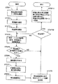
次には、図1を参照しながら概略的な構成が前述されたこの発明の1つの実施の形態に従った射出成形機の射出速度制御装置の動作を図2の流れ図を参照しながら詳細に説明する。
まず最初に射出成形機22から射出成形型14内の型凹所10a,10bに射出される溶融材料の速度(一定射出速度)を手動で図1の記憶装置42に設定する(STEP1)。なおこの一定射出速度は、射出成形機22の製造業者や販売業者や使用者により溶融材料の種類や射出成形型14内の型凹所10a,10bの大きさや形状等を基礎にして作成されているデータから選択することが出来る。
次には、射出中の溶融材料の圧力(この実施の形態では樹脂圧力)を表している型内樹脂圧力またはノズル内樹脂圧力または射出スクリュー30のスクリュー駆動油圧手段32における油圧(即ち、射出油圧)または型開量の少なくともいずれか1つ、好ましくは複数の基準値を、溶融材料の圧力(この実施の形態では樹脂圧力)の基準値として射出スクリュー位置または射出経過時間の関数として記憶装置42に設定する(STEP2)。
そして射出成形加工を開始する(STEP3)と同時に図1の型開量検知器16,型内樹脂圧力検知器18,ノズル内樹脂圧力検知器28,及び射出油圧検知器34による型開量,型内溶融樹脂圧力,ノズル内溶融樹脂圧力,及び射出油圧の少なくともいずれか1つ、好ましくは複数の検出を開始し(STEP4)、検出した型開量,型内溶融樹脂圧力,ノズル内溶融樹脂圧力,及び射出油圧の少なくともいずれか1つ、好ましくは複数が射出速度演算装置38において記憶装置42に設定されている基準値と比較される(STEP5)。
なお上記複数の検出は同時に行うことが出来るし、また所望の順序で行うことも出来る。この実施の形態では、圧力検出周期は射出速度制御周期でもあり、射出成形機22における溶融樹脂の射出充填時間に対して例えば分数比や%比の如き比率で設定されていることが好ましい。
ここにおいて、少なくともいずれか1つ、好ましくは複数のいずれもが対応する基準圧力に到達していない場合には、射出スクリュー30が射出スクリュー終端位置に到達したかどうか(即ち、射出成形加工が終了したかどうか)が判断され(STEP10)、射出スクリュー30が射出スクリュー終端位置に到達していなければ上述したSTEP4に戻る。
上述したSTEP5において、検出した型開量,型内溶融樹脂圧力,ノズル内溶融樹脂圧力,及び射出油圧の少なくともいずれか1つ、好ましくは複数の中の1つが基準圧力を越えた場合には、基準圧力を越えた上記いずれか1つ、好ましくは複数の中の1つと対応する基準圧力との偏差量が射出速度演算装置38において求められる(STEP6)。
射出速度演算装置38はさらに、この偏差を無くするような射出速度の修正値を得る為に、STEP6において求められた偏差量と検出した型開量,型内溶融樹脂圧力,ノズル内溶融樹脂圧力,及び射出油圧の少なくともいずれか1つ、好ましくは複数の中の1つが基準圧力を越えた時点の射出速度とからPI(比例積分)演算またはPID(比例積分微分)演算により上述した偏差量に応じて修正された射出速度修正値を得る(STEP7)。
射出速度制御装置40は射出速度演算装置38において上述した如くして得ることが出来た射出速度修正値に従い油圧流体流量制御装置44を制御する(STEP8)。
このようにして得られた射出速度の修正値と修正が行われた時の射出スクリュー30の位置は、図1に示された記憶装置42に記憶される(STEP9)。
さらに射出スクリュー30が射出スクリュー終端位置に到達したかどうか(即ち、射出成形作業が終了したかどうか)が判断され(STEP10)、射出スクリュー30が射出スクリュー終端位置に到達していなければ上述したSTEP4に戻る。
STEP10において射出スクリュー30が射出スクリュー終端位置に到達していると判断された場合には、射出成形加工の開始時点から射出スクリュー30が射出スクリュー終端位置に到達した射出成形加工の終了時点までの上述した射出速度の修正値や修正が行なわれた時の射出スクリュー30の位置が記憶装置42から読み出され、射出成形機22に予め設定されている所定の射出速度の修正可能な段数で構成された射出速度パターンに変換される(STEP11)。
これにより、この発明の1つの実施の形態に従った射出速度制御装置を使用した射出成形機22において射出成形加工を行う時に、基準圧力よりも大きくなった時点での溶融樹脂の検出圧力の圧力上昇率に対応して修正された射出速度を得ることが出来、ひいては修正された射出速度により達成される検出圧力が基準圧力から振れる量を小さくすることが出来て、新たな射出成形型に最適な射出速度の制御を熟練した作業員ではなくとも容易に短時間で得ることが出来る、
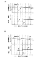
図3の(A)には、従来の射出成形機の射出速度制御装置において射出速度 (即ち射出プランジャの移動速度)に比べて型内溶融樹脂圧(型内樹脂圧力)PA の上昇速度(即ち上昇率)が比較的小さい場合について、射出成形加工中に型開量検知器,型内樹脂圧力検知器,ノズル内樹脂圧力検知器,及び射出油圧検知器により検知される型開量,型内溶融樹脂圧力,ノズル内溶融樹脂圧力,及び射出油圧の中の代表としての型内溶融樹脂圧力(型内樹脂圧力)PA が予め設定されている基準圧PS を越えた場合に、従来の射出成形機の射出速度制御装置が型内溶融樹脂圧力(型内樹脂圧力)PA を基準圧PS よりも低下させようとして、型内溶融樹脂圧力(型内樹脂圧力)PA が予め設定されている基準圧PS を越えている間に所定の減速率で射出速度を低下させる様子を示している。
なおここでは、型内樹脂圧力検知器による型内溶融樹脂圧力(型内樹脂圧力)PA の検知は射出プランジャ位置の変位に沿い所定の間隔で配置された多数の一点鎖線で示す所定の周期で行われている。
この図からは、射出速度(即ち射出プランジャの移動速度)に比べて型内溶融樹脂圧力(型内樹脂圧力)PA の上昇速度(即ち上昇率)が比較的小さい場合には、型内溶融樹脂圧力(型内樹脂圧力)PA が予め設定されている基準圧PS を越えたことを最初に検知した時P1 に、従来の射出成形機の射出速度制御装置の射出速度演算装置が型内溶融樹脂圧力(型内樹脂圧力)PA が基準圧PS を越えたことを最初に検知した時P1 の射出充填速度V0 に所定の一定の減速率を乗じて求めた結果の修正された射出充填速度V1 では、修正された射出速度V1 によりもたらされ検知された型内溶融樹脂圧力(型内樹脂圧力)PA が基準圧PS から急激に大幅に低下してしまうことが分かる。
即ち、上述した一定の減速率により修正された射出速度V1 により達成される修正された検出圧力PA と修正前の検出圧力PA との差異が大きくなって、射出成形加工の終了までに溶融樹脂の検出圧力PA が基準圧PS に到達しなくなってしまったり、溶融樹脂の検出圧力PA が基準圧PS に到達するのに要する時間が遅れて射出成形型14内の型凹所10a,10b中に充分な溶融樹脂が充填されなくなる。
図3の(B)には、この発明の1つの実施の形態に従った射出成形機の射出速度制御装置において、図3の(A)の場合と同様に、射出速度(即ち射出プランジャの移動速度)に比べて型内溶融樹脂圧(型内樹脂圧力)PA の上昇速度(即ち上昇率)が比較的小さい場合について、射出成形加工中に型開量検知器16,型内樹脂圧力検知器18,ノズル内樹脂圧力検知器28,及び射出油圧検知器34により検知される型開量,型内溶融樹脂圧力,ノズル内溶融樹脂圧力,及び射出油圧の中の代表としての型内溶融樹脂圧(型内樹脂圧力)PA が予め設定されている基準圧PS を越えた場合に、この発明の1つの実施の形態に従った射出成形機の射出速度制御装置が型内溶融樹脂圧(型内樹脂圧力)PA を基準圧PS よりも低下させようとして、型内溶融樹脂圧(型内樹脂圧力)PA が予め設定されている基準圧PS を越えている間に上記上昇率に対応して射出速度を低下させる様子を示している。
なおここでも、型内樹脂圧力検知器による型内溶融樹脂圧力(型内樹脂圧力)PA の検知は射出プランジャ位置の変位に沿い所定の間隔で配置された多数の一点鎖線で示す所定の周期で行われている。
この図からは、射出速度(即ち射出プランジャの移動速度)に比べて型内溶融樹脂圧力(型内樹脂圧力)PA の上昇速度(即ち上昇率)が比較的小さい場合には、型内溶融樹脂圧力(型内樹脂圧力)PA が予め設定されている基準圧PS を越えたことを最初に検出した時P1 に、この発明の1つの実施の形態に従った射出成形機の射出速度制御装置の射出速度演算装置38が基準圧PS を越えて最初に検出した型内溶融樹脂圧力(型内樹脂圧力)PA と基準圧PS との偏差量を求め、この偏差量と検出した型内溶融樹脂圧力(型内樹脂圧力)PA が基準圧PS を越えた時点の射出速度VO とからPI(比例積分)演算またはPID(比例積分微分)演算により上記射出速度の修正値を求めた結果の最初に修正された射出速度V1 ´では、最初に修正された射出速度V1 ´に対応して検知される型内溶融樹脂圧力(型内樹脂圧力)PA が基準圧PS から急激に大幅に低下することがないことが分かる。
即ち、上述した如くして最初に修正された射出充填速度V1 ´により達成される最初に修正された検出圧力PA と修正前の検出圧力PA との差異は、基準圧PS を越えて最初に検出した型内溶融樹脂圧力(型内樹脂圧力)PA と基準圧PS との偏差量(即ち基準圧PS を越えて最初に検出した型内溶融樹脂圧力(型内樹脂圧力)PA の上昇速度または上昇率)に対応していて大きくならず、射出成形加工の終了までに溶融樹脂の検出圧力PA が速やかに基準圧PS に到達し、射出成形型14内の型凹所10a,10b中に充分な溶融樹脂を充填させることが出来る。
図4の(A)には、従来の射出成形機の射出速度制御装置において射出速度 (即ち射出プランジャの移動速度)に比べて型内溶融樹脂圧力(型内樹脂圧力)PA の上昇速度(即ち上昇率)が比較的大きな場合について、射出成形加工中に型開量検知器,型内樹脂圧力検知器,ノズル内樹脂圧力検知器,及び射出油圧検知器により検知される型開量,型内溶融樹脂圧力,ノズル内溶融樹脂圧力,及び射出油圧の中の代表としての型内溶融樹脂圧力(型内樹脂圧力)PA が予め設定されている基準圧PS を越えた場合に、従来の射出成形機の射出速度制御装置が型内溶融樹脂圧力(型内樹脂圧力)PA を基準圧PS よりも低下させようとして、型内溶融樹脂圧力(型内樹脂圧力)PA が予め設定されている基準圧PS を越えている間に所定の減速率で射出速度を低下させる様子を示している。
なおここでも、型内樹脂圧力検知器による型内溶融樹脂圧力(型内樹脂圧力)PA の検知は射出プランジャ位置の変位に沿い所定の間隔で配置された多数の一点鎖線で示す所定の周期で行われている。
この図からは、射出速度(即ち射出プランジャの移動速度)に比べて型内溶融樹脂圧力(型内樹脂圧力)PA の上昇速度(即ち上昇率)が比較的大きな場合には、型内溶融樹脂圧力(型内樹脂圧力)PA が予め設定されている基準圧PS を越えたことを最初に検知した時P1 に、従来の射出成形機の射出速度制御装置の射出速度演算装置が型内溶融樹脂圧力(型内樹脂圧力)PA が基準圧PS を越えたことを最初に検知した時P1 の射出速度V0 に所定の一定の減速率を乗じて求めた結果の最初に修正された射出速度V1 では、最初に修正された射出速度V1 に対応して検知された型内溶融樹脂圧力(型内樹脂圧力)PA がなかなか低下しないことが分かる。この結果として、所定の周期で検知された型内溶融樹脂圧力(型内樹脂圧力)PA が予め設定されている基準圧PS よりも減少するまで、所定の周期で所定の一定の減速率を乗じて引き続き修正された射出速度V2 ,V3 が求められるが、検知された型内溶融樹脂圧力(型内樹脂圧力)PA が基準圧PS よりも減少に変更された時点では、検知された型内溶融樹脂圧力(型内樹脂圧力)PA の上昇が続いている間に修正が重ねられた後の射出速度V3 に従い検知された型内溶融樹脂圧力(型内樹脂圧力)PA が急激に減少するようになり、やがて基準圧PS から急激に大幅に低下してしまうことが分かる。
即ち、修正が重ねられた後の射出速度V3 により達成される修正が重ねられた後の検出圧力PA と修正前の検出圧力PA との差異が大きくなって、射出成形加工の終了までに溶融樹脂の検出圧力PA が基準樹脂圧PS に到達しなくなってしまったり、溶融樹脂の検出圧力PA が基準圧PS に到達するのに要する時間が遅れて射出成形型14内の型凹所10a,10b中に充分な溶融樹脂が充填されなくなる。
図4の(B)には、この発明の1つの実施の形態に従った射出成形機の射出速度制御装置において、図4の(A)の場合と同様に、射出速度(即ち射出プランジャの移動速度)に比べて型内溶融樹脂圧力(型内樹脂圧力)PA の上昇速度 (即ち上昇率)が比較的大きな場合について、射出成形加工中に型開量検知器16,型内樹脂圧力検知器18,ノズル内樹脂圧力検知器28,及び射出油圧検知器34により検知される型開量,型内溶融樹脂圧力,ノズル内溶融樹脂圧力,及び射出油圧の中の代表としての型内溶融樹脂圧力(型内樹脂圧力)PA が予め設定されている基準圧PS を越えた場合に、この発明の1つの実施の形態に従った射出成形機の射出速度制御装置が型内溶融樹脂圧力(型内樹脂圧力)PA を基準圧PS よりも低下させようとして、型内溶融樹脂圧力(型内樹脂圧力)PA が予め設定されている基準圧PS を越えている間の射出速度を上記上昇率に対応して低下させる様子を示している。
なおここでも、型内樹脂圧力検知器18による型内溶融樹脂圧力(型内樹脂圧力)PA の検知は射出プランジャ位置の変位に沿い所定の間隔で配置された多数の一点鎖線で示す所定の周期で行われている。
この図からは、射出速度(即ち射出プランジャの移動速度)に比べて型内溶融樹脂圧力(型内樹脂圧力)PA の上昇速度(即ち上昇率)が比較的大きな場合には、型内溶融樹脂圧力(型内樹脂圧力)PA が予め設定されている基準圧PS を越えたことを最初に検出した時P1 に、この発明の1つの実施の形態に従った射出成形機の射出速度制御装置の射出速度演算装置38が基準圧PS を越えて最初に検出した型内溶融樹脂圧力(型内樹脂圧力)PA と基準圧PS との偏差量を求め、この偏差量と検出した型内溶融樹脂圧力(型内樹脂圧力)PA が基準圧PS を越えた時点の射出速度VO とからPI(比例積分)演算またはPID(比例積分微分)演算により上記射出速度の修正値を求めた結果の最初に修正された射出速度V1 ´では、最初に修正された射出充填速度V1 ´によりもたらされて検知された型内溶融樹脂圧力(型内樹脂圧力)PA が急激に大幅に低下することが分かる。
しかしながら、次の検出周期の時P2 に検出された型内溶融樹脂圧力(型内樹脂圧力)PA も予め設定されている基準圧PS を越えていることにより、この発明の1つの実施の形態に従った射出成形機の射出速度制御装置の射出速度演算装置38が基準圧PS を越えて次の検出周期の時P2 に検出した型内溶融樹脂圧力(型内樹脂圧力)PA と基準圧PS との偏差量を求め、この偏差量と次の検出周期の時P2 に検出された型内溶融樹脂圧力(型内樹脂圧力)PA をもたらした最初に修正された射出充填速度V1 ´とからPI(比例積分)演算またはPID (比例積分微分)演算により求めた結果の次の検出周期の時P2 に修正された射出速度V2 ´では、次の検出周期の時P2 に修正された射出速度V2 ´によりもたらされ検知された型内溶融樹脂圧力(型内樹脂圧力)PA が基準圧PS から急激に大幅に低下しないことが分かる。
即ち、上述した如くして最初に修正された射出速度V1 ´によりもたらされる最初に修正された型内溶融樹脂圧力(型内樹脂圧力)PA と最初の修正前の型内溶融樹脂圧力(型内樹脂圧力)PA との差異は、基準圧PS を越えて最初に検出した型内溶融樹脂圧力(型内樹脂圧力)PA と基準圧PS との偏差量(即ち基準圧PS を越えて最初に検出した型内溶融樹脂圧力(型内樹脂圧力)PA の上昇速度または上昇率)に対応していて大きく、またこれに続いて修正された射出充填速度V2 ´により達成される次に修正された型内溶融樹脂圧力(型内樹脂圧力)PA と最初に修正された型内溶融樹脂圧力(型内樹脂圧力)PA との差異は、基準圧PS を越えて次の検出周期に検出した型内溶融樹脂圧力(型内樹脂圧力)PA と基準圧PS との偏差量(即ち基準圧PS を越えて次の検出周期に検出した型内溶融樹脂圧力(型内樹脂圧力)PA の上昇速度または上昇率)に対応していて小さい。この為に射出成形加工の終了までに溶融樹脂の検出圧力PA が速やかに基準圧PS に収束し、射出成形型14内の型凹所10a,10b中に充分な溶融樹脂を充填させることが出来る。
【発明の効果】
以上詳述した如く、この発明に従った射出成形機の射出速度制御装置によれば、基準圧力よりも大きくなった溶融材料の検出圧力の圧力上昇率に対応して修正された射出速度を得ることが出来、ひいては修正された射出速度により達成される検出圧力が基準圧力から振れる量を小さくすることが出来て、新たな射出成形型に最適な射出速度の制御を熟練した作業員ではなくとも容易に短時間で得ることが出来る。
【図面の簡単な説明】
【図1】この発明の1つの実施の形態に従った射出成形機の射出速度制御装置の構成を概略的に示す図である。
【図2】図1の射出成形機の射出速度制御装置の動作を示す流れ図である。
【図3】(A)は、従来の射出成形機の射出速度制御装置において射出速度(即ち射出プランジャの移動速度)に比べて型内溶融樹脂圧力(型内樹脂圧力)PA の上昇速度(即ち上昇率)が比較的小さい場合について、射出速度とそれに対応する型内樹脂圧力PA との関係を、型内樹脂圧力PA が予め設定されている基準圧PS を越えた場合に、従来の射出成形機の射出速度制御装置が上記比較的小さな上昇率とは無関係に射出速度を比較的大きく低下させてそれに対応する型内樹脂圧力が急激に低下する様子とともに示しており、
(B)は、図1の射出成形機の射出速度制御装置において、上記(A)の場合と同様に、射出速度(即ち射出プランジャの移動速度)に比べて型内溶融樹脂圧(型内樹脂圧力)PA の上昇速度(即ち上昇率)が比較的小さい場合について、射出速度とそれに対応する型内樹脂圧力PA との関係を、型内樹脂圧力PA が予め設定されている基準圧PS を越えた場合に、図1の射出成形機の射出速度制御装置が上記比較的小さな上昇率に対応して射出速度を比較的小さく低下させてそれに対応する型内樹脂圧力が緩やかに低下する様子とともに示している。
【図4】(A)は、従来の射出成形機の射出速度制御装置において射出速度(即ち射出プランジャの移動速度)に比べて型内溶融樹脂圧力(型内樹脂圧力)PA の上昇速度(即ち上昇率)が比較的大きな場合について、射出速度とそれに対応する型内樹脂圧力PA との関係を、型内樹脂圧力PA が予め設定されている基準圧PS を越えた場合に、従来の射出成形機の射出速度制御装置が上記比較的大きな上昇率とは無関係に射出速度を序々に緩やかに低下させてそれに対応する型内樹脂圧力が最初は緩やかに最終的には急激に低下する様子とともに示しており、
(B)は、図1の射出成形機の射出速度制御装置において、上記(A)の場合と同様に、射出速度(即ち射出プランジャの移動速度)に比べて型内溶融樹脂圧(型内樹脂圧力)PA の上昇速度(即ち上昇率)が比較的小さい場合について、射出速度とそれに対応する型内樹脂圧力PA との関係を、型内樹脂圧力PA が予め設定されている基準圧PS を越えた場合に、図1の射出成形機の射出速度制御装置が上記比較的大きな上昇率に対応して射出速度を最初は急激に最終的には緩やかに低下させてそれに対応する型内樹脂圧力が最初は急激に最終的には緩やかに低下する様子とともに示している。
【符号の説明】
12 射出成形機
14 射出成形型
16 型開量検知器
18 型内樹脂圧力検知器
28 ノズル内樹脂圧力検知器
30 射出スクリュ−
34 射出油圧検知器
38 射出速度演算装置DETAILED DESCRIPTION OF THE INVENTION
BACKGROUND OF THE INVENTION
The present invention relates to an injection speed control apparatus that is used in an injection molding machine that injects a molten material into an injection mold by moving a screw, and controls the injection speed of the molten material.
[Prior art]
Conventionally, when injection molding processing is performed by an injection molding machine using a new injection mold, first, several trial runs are made to produce a product with sufficient quality from the new injection mold. Thus, it is necessary to set the control conditions of the injection speed (that is, the molten material injection pressure) suitable for the new injection mold.
Conventionally, the control conditions of injection speed (ie, molten material injection pressure) suitable for such new injection molds are set by skilled workers by the type of molten resin and the size and shape of the mold recess in the injection mold. It was done with intuition and experience in consideration of the above.
However, Japanese Patent Laid-Open No. 7-186231 discloses a method for automatically and relatively easily setting the control conditions of the injection speed (ie, the molten material injection pressure) even if it is not a skilled worker. Here, when setting the injection speed control conditions, first of all, manually injection molding a constant injection speed of the molten material (usually molten resin) injected from the injection molding machine into the mold recess in the injection mold. Temporarily set in the injection speed control device of the machine. Further, a reference resin pressure that is a reference during the injection molding process is also set in the injection speed control device. This temporary constant injection speed and reference resin pressure are created by manufacturers, distributors and users of injection molding machines based on the type of molten resin and the size and shape of the mold recess in the injection mold. You can select from existing data.
Next, the injection molding process is started, and the detection of the pressure of the molten resin that is injected and filled into the mold recess in the injection mold is started together with the start of the injection molding process. If the detected pressure of the molten resin becomes larger than the reference resin pressure during the injection molding process, the injection speed at the time when the detected pressure of the molten resin becomes larger than the reference resin pressure is multiplied by a predetermined deceleration rate set in advance. The corrected injection speed is set, and the injection molding process is continued according to the corrected injection speed. This predetermined deceleration rate is also selected from data created by manufacturers, distributors and users of injection molding machines based on the type of molten resin and the size and shape of the mold recess in the injection mold. I can do it.
Such correction of the injection speed is repeatedly performed at a predetermined cycle while the detected pressure of the molten resin is higher than the reference resin pressure during the injection molding process. When the detected pressure of the molten resin becomes lower than the reference resin pressure, the corrected injection speed adopted when the detected pressure of the molten resin becomes lower than the reference resin pressure is maintained as it is.
[Problems to be solved by the invention]
In the conventional injection speed control device for an injection molding machine as described above, the deceleration rate described above is independent of the pressure increase rate (that is, the pressure increase rate) of the detected pressure of the molten resin when it becomes higher than the reference resin pressure. The constant is causing some problems as described below.
For example, when the pressure increase rate is relatively small and the above-described constant deceleration rate is larger than the pressure increase rate, the detected pressure of the molten material is set to the reference pressure using the injection speed control device as described above. When calculating the correction value of the injection speed that eliminates the difference between the detected pressure and the reference pressure in the range that exceeds, it takes time until the actual pressure drop occurs in the molten material due to the correction of the injection speed. Since the injection speed is continually corrected until the detected pressure reaches the reference pressure, the injection speed eventually approaches very zero, and the flow rate of the molten material may become extremely zero. This also causes molding defects such as sink marks and streamlines in the molded product molded by the injection molding process.
In addition, when the pressure increase rate is relatively large and the above-described constant deceleration rate is small compared to the pressure increase rate, the molten material does not decrease in pressure even though the injection speed is corrected to be lower. The detected pressure greatly exceeds the reference pressure, and eventually the injection mold may be damaged.
For this reason, in the injection speed control device of the conventional injection molding machine as described above, it is necessary to perform a test shot required until a control condition of an injection speed (that is, a molten resin injection pressure) suitable for a new injection mold can be set. It was difficult to reduce the number of times unless it was a skilled worker.
The present invention has been made under the above circumstances, and the object of the present invention is to obtain a corrected injection speed corresponding to the rate of pressure increase of the detected pressure of the molten material that has become larger than the reference pressure, and thus is corrected. The detection pressure achieved by the injection speed can be reduced from the reference pressure, and the optimum injection speed control conditions for a new injection mold can be easily obtained in a short time even without skilled workers. It is to provide an injection speed control device for an injection molding machine.
[Means for Solving the Problems]
In order to solve the above-mentioned object of the present invention, an injection filling speed control device for an injection molding machine according to the present invention is used in: an injection molding machine for injecting molten material into an injection mold by moving a screw. The pressure of the molten material is detected during the movement of the screw, the detected pressure of the molten material is compared with a preset reference pressure, and the detected pressure and the detected pressure are within the range where the detected pressure exceeds the reference pressure. A correction value for the injection speed that eliminates the difference from the reference pressure is calculated and obtained; in the calculation, a deviation amount between the detected pressure and the reference pressure is obtained, and the deviation amount and the detected pressure exceed the reference pressure. The correction value of the injection speed is obtained by PI (proportional integral) calculation or PID (proportional integral derivative) calculation from the injection speed at the time point.
In such a configuration, when calculating the correction value of the injection speed that eliminates the difference between the pressure of the molten material detected during the movement of the screw and the preset reference pressure, A deviation amount between the detected pressure and the reference pressure is obtained, and the injection is performed by PI (proportional integral) calculation or PID (proportional integral derivative) calculation from the deviation amount and the injection speed when the detected pressure exceeds the reference pressure. Since the speed correction value is obtained, a corrected injection speed corresponding to the pressure increase rate of the detected pressure of the molten material that has become larger than the reference pressure can be obtained, and thus the detection achieved by the corrected injection speed. The amount by which the pressure swings from the reference pressure can be reduced.
In addition, when the injection speed is constant as in the conventional example of Japanese Patent Laid-Open No. 7-186231 described above, the detected pressure of the molten material tends to increase substantially proportionally, and PI (proportional integral) calculation or PID (proportional integral differential) ) Setting of the correction value of the injection speed by calculation is not performed when the detected pressure falls below the reference pressure because the detected pressure exceeds the reference pressure and is not performed when the detected pressure falls below the reference pressure. Detection pressure overshoot and hunting phenomenon can be prevented.
DETAILED DESCRIPTION OF THE INVENTION
Hereinafter, an injection speed control device for an injection molding machine according to an embodiment of the present invention will be described in detail with reference to the accompanying drawings.
FIG. 1 is a diagram schematically showing a configuration of an injection speed control device for an injection molding machine according to one embodiment of the present invention.
In this embodiment, the mold
An
Each of the in-nozzle
The injection
The
Further, an injection screw
Next, the operation of the injection speed control device of the injection molding machine according to the embodiment of the present invention, whose schematic configuration is described above with reference to FIG. 1, will be described in detail with reference to the flowchart of FIG. explain.
First, the speed (fixed injection speed) of the molten material injected from the
Next, the in-mold resin pressure representing the pressure of the molten material during injection (resin pressure in this embodiment), the resin pressure in the nozzle, or the hydraulic pressure in the screw drive hydraulic means 32 of the injection screw 30 (that is, injection hydraulic pressure). ) Or at least one of the mold opening amounts, preferably a plurality of reference values, as a reference value for the pressure of the molten material (resin pressure in this embodiment) as a function of the injection screw position or the injection elapsed time. (STEP 2).
At the same time as the injection molding process is started (STEP 3), the mold opening amount and mold by the mold
The plurality of detections can be performed simultaneously or in a desired order. In this embodiment, the pressure detection cycle is also an injection speed control cycle, and is preferably set at a ratio such as a fraction ratio or a% ratio with respect to the injection filling time of the molten resin in the
Here, if at least any one, preferably all of the plurality, has not reached the corresponding reference pressure, whether or not the
In STEP 5 described above, when at least one of the detected mold opening amount, in-mold molten resin pressure, in-nozzle molten resin pressure, and injection hydraulic pressure, preferably one of the plurality exceeds the reference pressure, A deviation amount between any one of the above, preferably one of the plurality exceeding the reference pressure, and the corresponding reference pressure is obtained in the injection speed calculation device 38 (STEP 6).
Further, in order to obtain a correction value of the injection speed so as to eliminate this deviation, the injection
The injection
The correction value of the injection speed obtained in this way and the position of the
Further, it is determined whether or not the
If it is determined in STEP 10 that the
As a result, when the injection molding process is performed in the
FIG. 3A shows an in-mold molten resin pressure (in-mold resin pressure) P as compared with the injection speed (that is, the movement speed of the injection plunger) in an injection speed control device of a conventional injection molding machine. A Die detected by mold opening detector, in-mold resin pressure detector, in-nozzle resin pressure detector, and injection hydraulic pressure detector during injection molding when the rate of increase in the rate of movement (ie rate of increase) is relatively small In-mold molten resin pressure (in-mold resin pressure) P as a representative of opening amount, in-mold molten resin pressure, in-nozzle molten resin pressure, and injection hydraulic pressure A Is a preset reference pressure P S In the case of exceeding the injection pressure control device of the conventional injection molding machine, the in-mold molten resin pressure (in-mold resin pressure) P A Reference pressure P S In-mold molten resin pressure (resin pressure in mold) P A Is a preset reference pressure P S It shows a state in which the injection speed is reduced at a predetermined deceleration rate while the value exceeds.
Here, in-mold molten resin pressure (in-mold resin pressure) P by the in-mold resin pressure detector is used. A Is detected at a predetermined cycle indicated by a number of alternate long and short dash lines arranged at predetermined intervals along the displacement of the injection plunger position.
From this figure, compared to the injection speed (that is, the movement speed of the injection plunger), the in-mold molten resin pressure (in-mold resin pressure) P A In the case where the rate of increase (that is, the rate of increase) is relatively small, the in-mold molten resin pressure (in-mold resin pressure) P A Is a preset reference pressure P S P when the first detection of exceeding 1 In addition, the injection speed calculation device of the injection speed control device of the conventional injection molding machine is an in-mold molten resin pressure (in-mold resin pressure) P A Is the reference pressure P S P when the first detection of exceeding 1 Injection filling speed V 0 The injection filling speed V corrected as a result obtained by multiplying the predetermined constant deceleration rate by 1 Then, the corrected injection speed V 1 In-mold molten resin pressure (resin pressure in mold) P A Is the reference pressure P S It turns out that it falls rapidly drastically.
That is, the injection speed V corrected by the constant deceleration rate described above. 1 The corrected detection pressure P achieved by A And detected pressure P before correction A And the detected pressure P of the molten resin before the end of the injection molding process A Is the reference pressure P S Or the detected pressure P of the molten resin A Is the reference pressure P S The time required to reach the position is delayed, and the mold recesses 10a and 10b in the
FIG. 3 (B) shows an injection speed (that is, movement of the injection plunger) in the injection speed control apparatus for an injection molding machine according to one embodiment of the present invention, as in FIG. 3 (A). In-mold molten resin pressure (in-mold resin pressure) P A In the case where the rising speed (ie, the rising rate) is relatively small, the mold
Here again, the in-mold molten resin pressure (in-mold resin pressure) P by the in-mold resin pressure detector is used. A This detection is performed at a predetermined cycle indicated by a number of alternate long and short dash lines arranged at predetermined intervals along the displacement of the injection plunger position.
From this figure, compared to the injection speed (that is, the movement speed of the injection plunger), the molten resin pressure in the mold (resin pressure in the mold) P A In the case where the rate of increase (that is, the rate of increase) is relatively small, the in-mold molten resin pressure (in-mold resin pressure) P A Is a preset reference pressure P S P when first detected that 1 In addition, the injection speed calculation device 38 of the injection speed control device of the injection molding machine according to one embodiment of the present invention provides the reference pressure P S In-mold molten resin pressure (resin pressure in mold) P detected first beyond A And reference pressure P S The amount of deviation is calculated, and the amount of deviation and the detected molten resin pressure (resin pressure in the mold) P A Is the reference pressure P S Injection speed V O The injection speed V corrected at the beginning of the result of obtaining the correction value of the injection speed by PI (proportional integral) calculation or PID (proportional integral derivative) calculation from 1 In ´, the first corrected injection speed V 1 In-mold molten resin pressure (in-mold resin pressure) P detected corresponding to ' A Is the reference pressure P S It can be seen that there is no drastic drastic decrease.
That is, the injection filling speed V first corrected as described above. 1 The first corrected detected pressure P achieved by ' A And detected pressure P before correction A The difference from the reference pressure P S In-mold molten resin pressure (resin pressure in mold) P detected first beyond A And reference pressure P S Deviation (ie, reference pressure P S In-mold molten resin pressure (resin pressure in mold) P detected first beyond A The rising pressure or the rising rate of the molten resin is not increased, and the detected pressure P of the molten resin is reached by the end of the injection molding process. A Is promptly the reference pressure P S The mold recesses 10a and 10b in the
FIG. 4A shows the in-mold molten resin pressure (in-mold resin pressure) P as compared with the injection speed (that is, the movement speed of the injection plunger) in the injection speed control device of the conventional injection molding machine. A Die detected by mold opening detector, in-mold resin pressure detector, in-nozzle resin pressure detector, and injection hydraulic pressure detector during injection molding when the rate of increase in the rate of movement (ie rate of increase) is relatively large In-mold molten resin pressure (in-mold resin pressure) P as a representative of opening amount, in-mold molten resin pressure, in-nozzle molten resin pressure, and injection hydraulic pressure A Is a preset reference pressure P S In the case of exceeding the injection pressure control device of the conventional injection molding machine, the in-mold molten resin pressure (in-mold resin pressure) P A Reference pressure P S In-mold molten resin pressure (resin pressure in mold) P A Is a preset reference pressure P S It shows a state in which the injection speed is reduced at a predetermined deceleration rate while the value exceeds.
Here again, the in-mold molten resin pressure (in-mold resin pressure) P by the in-mold resin pressure detector is used. A Is detected at a predetermined cycle indicated by a number of alternate long and short dash lines arranged at predetermined intervals along the displacement of the injection plunger position.
From this figure, compared to the injection speed (that is, the movement speed of the injection plunger), the molten resin pressure in the mold (resin pressure in the mold) P A In the case where the rate of increase (that is, the rate of increase) is relatively large, the in-mold molten resin pressure (in-mold resin pressure) P A Is a preset reference pressure P S P when the first detection of exceeding 1 In addition, the injection speed calculation device of the injection speed control device of the conventional injection molding machine is an in-mold molten resin pressure (in-mold resin pressure) P A Is the reference pressure P S P when the first detection of exceeding 1 Injection speed V 0 The injection speed V corrected at the beginning of the result obtained by multiplying by a predetermined constant deceleration rate 1 Then, the first corrected injection speed V 1 In-mold molten resin pressure (in-mold resin pressure) P detected corresponding to A It turns out that does not fall easily. As a result, in-mold molten resin pressure (in-mold resin pressure) P detected at a predetermined cycle. A Is a preset reference pressure P S The injection speed V is continuously corrected by multiplying by a predetermined constant deceleration rate in a predetermined cycle until it decreases. 2 , V Three Is detected, but the detected in-mold molten resin pressure (in-mold resin pressure) P A Is the reference pressure P S When the pressure is changed to decrease, the detected in-mold molten resin pressure (in-mold resin pressure) P A The injection speed V after corrections are repeated while the rise continues Three In-mold molten resin pressure (in-mold resin pressure) P detected according to A Suddenly decreases, and eventually the reference pressure P S It turns out that it falls rapidly drastically.
That is, the injection speed V after the correction is repeated Three Detected pressure P after the correction achieved by A And detected pressure P before correction A And the detected pressure P of the molten resin before the end of the injection molding process A Is the standard resin pressure P S Or the detected pressure P of the molten resin A Is the reference pressure P S The time required to reach the position is delayed, and the mold recesses 10a and 10b in the
FIG. 4B shows the injection speed (that is, the movement of the injection plunger) in the injection speed control device for an injection molding machine according to one embodiment of the present invention, as in FIG. In-mold molten resin pressure (in-mold resin pressure) P A In the case where the rising speed (ie, the rate of increase) is relatively large, the mold
In this case as well, the in-mold molten resin pressure (in-mold resin pressure) P by the in-mold
From this figure, compared to the injection speed (that is, the movement speed of the injection plunger), the molten resin pressure in the mold (resin pressure in the mold) P A In the case where the rate of increase (that is, the rate of increase) is relatively large, the in-mold molten resin pressure (in-mold resin pressure) P A Is a preset reference pressure P S P when first detected that 1 In addition, the injection
However, at the next detection cycle, P 2 In-mold molten resin pressure (in-mold resin pressure) P detected in A Is a preset reference pressure P S The injection
That is, the first corrected injection speed V as described above. 1 The first corrected in-mold molten resin pressure (in-mold resin pressure) P caused by ' A And in-mold molten resin pressure (in-mold resin pressure) P before the first correction A The difference from the reference pressure P S In-mold molten resin pressure (resin pressure in mold) P detected first beyond A And reference pressure P S Deviation (ie, reference pressure P S In-mold molten resin pressure (resin pressure in mold) P detected first beyond A The injection filling speed V which is large and subsequently corrected. 2 Next corrected in-mold molten resin pressure (in-mold resin pressure) P achieved by ' A And the first corrected molten resin pressure (resin pressure in the mold) P A The difference from the reference pressure P S In-mold molten resin pressure (in-mold resin pressure) P detected in the next detection cycle A And reference pressure P S Deviation (ie, reference pressure P S In-mold molten resin pressure (in-mold resin pressure) P detected in the next detection cycle A The rate of increase or rate of increase is small. For this reason, the detected pressure P of the molten resin by the end of the injection molding process A Is promptly the reference pressure P S And the mold recesses 10a and 10b in the
【The invention's effect】
As described above in detail, according to the injection speed control device for an injection molding machine according to the present invention, a corrected injection speed is obtained in accordance with the rate of increase in the detected pressure of the molten material that has become larger than the reference pressure. The detection pressure achieved by the modified injection speed can be reduced from the reference pressure, and the optimum injection speed control for a new injection mold can be controlled even by a skilled worker. It can be easily obtained in a short time.
[Brief description of the drawings]
FIG. 1 is a diagram schematically showing a configuration of an injection speed control device of an injection molding machine according to one embodiment of the present invention.
2 is a flowchart showing the operation of an injection speed control device of the injection molding machine of FIG. 1. FIG.
FIG. 3A is a view showing an in-mold molten resin pressure (in-mold resin pressure) P compared with an injection speed (that is, a movement speed of an injection plunger) in an injection speed control device of a conventional injection molding machine. A The injection speed and the corresponding in-mold resin pressure P in the case where the ascent rate (ie, rate of increase) is relatively small A In-mold resin pressure P A Is a preset reference pressure P S When the injection speed control device of the conventional injection molding machine exceeds the above, the injection speed is relatively reduced regardless of the relatively small increase rate, and the corresponding in-mold resin pressure rapidly decreases. Shows,
(B) is an in-mold molten resin pressure (in-mold resin) compared with the injection speed (that is, the movement speed of the injection plunger) in the injection speed control device of the injection molding machine of FIG. Pressure) P A The injection speed and the corresponding in-mold resin pressure P in the case where the ascent rate (ie, rate of increase) is relatively small A In-mold resin pressure P A Is a preset reference pressure P S 1, the injection speed control device of the injection molding machine of FIG. 1 reduces the injection speed relatively small corresponding to the relatively small increase rate, and the resin pressure in the mold correspondingly decreases gradually. Together with
FIG. 4A is a view showing an in-mold molten resin pressure (in-mold resin pressure) P as compared with an injection speed (that is, a movement speed of an injection plunger) in an injection speed control device of a conventional injection molding machine. A Injection rate and the corresponding in-mold resin pressure P when the rate of increase (ie rate of increase) is relatively large A In-mold resin pressure P A Is a preset reference pressure P S The injection speed control device of the conventional injection molding machine gradually reduces the injection speed gradually regardless of the relatively large increase rate, and the corresponding in-mold resin pressure is gradually reduced at the beginning. It shows with a state of suddenly decreasing,
(B) is an in-mold molten resin pressure (in-mold resin) compared with the injection speed (that is, the movement speed of the injection plunger) in the injection speed control device of the injection molding machine of FIG. Pressure) P A The injection speed and the corresponding in-mold resin pressure P in the case where the ascent rate (ie, rate of increase) is relatively small A In-mold resin pressure P A Is a preset reference pressure P S In the case of exceeding the above, the injection speed control device of the injection molding machine in FIG. It is shown with how the pressure initially drops rapidly and finally slowly.
[Explanation of symbols]
12 Injection molding machine
14 Injection mold
16 type open detector
18 Resin pressure detector in mold
28 Nozzle resin pressure detector
30 Injection screw
34 Injection oil pressure detector
38 Injection speed calculation device
Claims (1)
スクリューの移動中に溶融材料の圧力を検出し、溶融材料の検出圧力を予め設定されている基準圧力と比較し、上記検出圧力が上記基準圧力を越えている範囲において上記検出圧力と上記基準圧力との差異を無くす射出速度の修正値を演算して求める射出速度制御装置であって、
上記演算においては、上記検出圧力と上記基準圧力との偏差量を求め、この偏差量と上記検出圧力が上記基準圧力を越えた時点の射出速度とからPI(比例積分)演算またはPID(比例積分微分)演算により上記射出速度の修正値を求める、
ことを特徴とする射出成形機の射出速度制御装置。Used in injection molding machines that inject and fill molten material into an injection mold by moving a screw,
The pressure of the molten material is detected during movement of the screw, the detected pressure of the molten material is compared with a preset reference pressure, and the detected pressure and the reference pressure are within a range where the detected pressure exceeds the reference pressure. a injection speed control device Ru determined by calculating the correction value of the injection speed to eliminate the difference between,
In the calculation, a deviation amount between the detected pressure and the reference pressure is obtained, and a PI (proportional integral) calculation or a PID (proportional integral) is calculated from the deviation amount and the injection speed when the detected pressure exceeds the reference pressure. Find the correction value of the injection speed by (differential) calculation.
An injection speed control device for an injection molding machine.
Priority Applications (1)
| Application Number | Priority Date | Filing Date | Title |
|---|---|---|---|
| JP13228397A JP3897397B2 (en) | 1997-05-22 | 1997-05-22 | Injection speed control device for injection molding machine |
Applications Claiming Priority (1)
| Application Number | Priority Date | Filing Date | Title |
|---|---|---|---|
| JP13228397A JP3897397B2 (en) | 1997-05-22 | 1997-05-22 | Injection speed control device for injection molding machine |
Publications (2)
| Publication Number | Publication Date |
|---|---|
| JPH10315290A JPH10315290A (en) | 1998-12-02 |
| JP3897397B2 true JP3897397B2 (en) | 2007-03-22 |
Family
ID=15077670
Family Applications (1)
| Application Number | Title | Priority Date | Filing Date |
|---|---|---|---|
| JP13228397A Expired - Fee Related JP3897397B2 (en) | 1997-05-22 | 1997-05-22 | Injection speed control device for injection molding machine |
Country Status (1)
| Country | Link |
|---|---|
| JP (1) | JP3897397B2 (en) |
Families Citing this family (3)
| Publication number | Priority date | Publication date | Assignee | Title |
|---|---|---|---|---|
| US6835337B2 (en) * | 2001-05-07 | 2004-12-28 | Munekata Co., Ltd. | Method for controlling the forward movement speed of the screw in an injection molding machine |
| CN112917855B (en) * | 2021-01-22 | 2022-08-30 | 杭州电子科技大学 | Flexible switching control method and device of injection molding machine |
| JP7625937B2 (en) | 2021-03-30 | 2025-02-04 | トヨタ自動車株式会社 | Injection molding machine, additive manufacturing device, and pressure control method |
-
1997
- 1997-05-22 JP JP13228397A patent/JP3897397B2/en not_active Expired - Fee Related
Also Published As
| Publication number | Publication date |
|---|---|
| JPH10315290A (en) | 1998-12-02 |
Similar Documents
| Publication | Publication Date | Title |
|---|---|---|
| US6056902A (en) | Method and apparatus for molding a plastic article including injecting based upon a pressure-dominated control algorithm after detecting an indicia of a decrease in the surface area of the melt front | |
| US5853630A (en) | Low pressure method for injection molding a plastic article | |
| GB2286145A (en) | Method for automatically setting injection moulding speed condition | |
| KR19980018302A (en) | Apparatus and apparatus for manufacturing article having computer readable program code for forming article | |
| JPS5835460B2 (en) | transfer molding machine | |
| JP3212237B2 (en) | Automatic setting method of injection molding speed condition of injection molding machine | |
| US5554326A (en) | Control method of injection molding machine | |
| JP3897397B2 (en) | Injection speed control device for injection molding machine | |
| EP3810393B1 (en) | Method for controlling an injection molding machine | |
| JPH07256712A (en) | Molding method for injection molding machine | |
| JPH10272663A (en) | Method for optimizing molding conditions of injection molding machine | |
| JPS636341B2 (en) | ||
| JP2807924B2 (en) | Control device for injection molding machine | |
| JPH08281756A (en) | Operation control method of injection molding machine | |
| JP3457839B2 (en) | Injection speed control device for injection molding machine | |
| JPH0679432A (en) | Automatic controller for injecting speed of injection forming apparatus | |
| JP3257767B2 (en) | Injection speed control device for injection molding machine | |
| JP3872446B2 (en) | Injection molding method | |
| JPS62199421A (en) | Method for molding control of injection molding machine using variable pump | |
| JPH10109339A (en) | Injection molding machine molding condition setting method | |
| JPH0541751U (en) | Injection molding equipment | |
| JP3142718B2 (en) | Control method of disk forming machine | |
| JPH0443493B2 (en) | ||
| JP2606977Y2 (en) | Injection molding equipment | |
| JPS5892510A (en) | Injection molding device for ceramic product |
Legal Events
| Date | Code | Title | Description |
|---|---|---|---|
| A61 | First payment of annual fees (during grant procedure) |
Free format text: JAPANESE INTERMEDIATE CODE: A61 Effective date: 20061219 |
|
| R150 | Certificate of patent or registration of utility model |
Free format text: JAPANESE INTERMEDIATE CODE: R150 |
|
| FPAY | Renewal fee payment (event date is renewal date of database) |
Free format text: PAYMENT UNTIL: 20100105 Year of fee payment: 3 |
|
| S531 | Written request for registration of change of domicile |
Free format text: JAPANESE INTERMEDIATE CODE: R313531 |
|
| FPAY | Renewal fee payment (event date is renewal date of database) |
Free format text: PAYMENT UNTIL: 20100105 Year of fee payment: 3 |
|
| R350 | Written notification of registration of transfer |
Free format text: JAPANESE INTERMEDIATE CODE: R350 |
|
| FPAY | Renewal fee payment (event date is renewal date of database) |
Free format text: PAYMENT UNTIL: 20100105 Year of fee payment: 3 |
|
| FPAY | Renewal fee payment (event date is renewal date of database) |
Free format text: PAYMENT UNTIL: 20110105 Year of fee payment: 4 |
|
| FPAY | Renewal fee payment (event date is renewal date of database) |
Free format text: PAYMENT UNTIL: 20120105 Year of fee payment: 5 |
|
| FPAY | Renewal fee payment (event date is renewal date of database) |
Free format text: PAYMENT UNTIL: 20130105 Year of fee payment: 6 |
|
| FPAY | Renewal fee payment (event date is renewal date of database) |
Free format text: PAYMENT UNTIL: 20130105 Year of fee payment: 6 |
|
| FPAY | Renewal fee payment (event date is renewal date of database) |
Free format text: PAYMENT UNTIL: 20140105 Year of fee payment: 7 |
|
| LAPS | Cancellation because of no payment of annual fees |