JP3893199B2 - Automatic paper feeder - Google Patents
Automatic paper feeder Download PDFInfo
- Publication number
- JP3893199B2 JP3893199B2 JP24702997A JP24702997A JP3893199B2 JP 3893199 B2 JP3893199 B2 JP 3893199B2 JP 24702997 A JP24702997 A JP 24702997A JP 24702997 A JP24702997 A JP 24702997A JP 3893199 B2 JP3893199 B2 JP 3893199B2
- Authority
- JP
- Japan
- Prior art keywords
- kicker
- cam
- paper
- deposit
- attached
- Prior art date
- Legal status (The legal status is an assumption and is not a legal conclusion. Google has not performed a legal analysis and makes no representation as to the accuracy of the status listed.)
- Expired - Fee Related
Links
Images


Classifications
-
- B—PERFORMING OPERATIONS; TRANSPORTING
- B65—CONVEYING; PACKING; STORING; HANDLING THIN OR FILAMENTARY MATERIAL
- B65H—HANDLING THIN OR FILAMENTARY MATERIAL, e.g. SHEETS, WEBS, CABLES
- B65H3/00—Separating articles from piles
- B65H3/02—Separating articles from piles using friction forces between articles and separator
- B65H3/06—Rollers or like rotary separators
- B65H3/0607—Rollers or like rotary separators cooperating with means for automatically separating the pile from roller or rotary separator after a separation step
-
- B—PERFORMING OPERATIONS; TRANSPORTING
- B65—CONVEYING; PACKING; STORING; HANDLING THIN OR FILAMENTARY MATERIAL
- B65H—HANDLING THIN OR FILAMENTARY MATERIAL, e.g. SHEETS, WEBS, CABLES
- B65H3/00—Separating articles from piles
- B65H3/02—Separating articles from piles using friction forces between articles and separator
- B65H3/06—Rollers or like rotary separators
- B65H3/0638—Construction of the rollers or like rotary separators
-
- B—PERFORMING OPERATIONS; TRANSPORTING
- B65—CONVEYING; PACKING; STORING; HANDLING THIN OR FILAMENTARY MATERIAL
- B65H—HANDLING THIN OR FILAMENTARY MATERIAL, e.g. SHEETS, WEBS, CABLES
- B65H3/00—Separating articles from piles
- B65H3/34—Article-retaining devices controlling the release of the articles to the separators
-
- B—PERFORMING OPERATIONS; TRANSPORTING
- B65—CONVEYING; PACKING; STORING; HANDLING THIN OR FILAMENTARY MATERIAL
- B65H—HANDLING THIN OR FILAMENTARY MATERIAL, e.g. SHEETS, WEBS, CABLES
- B65H3/00—Separating articles from piles
- B65H3/46—Supplementary devices or measures to assist separation or prevent double feed
- B65H3/52—Friction retainers acting on under or rear side of article being separated
- B65H3/5207—Non-driven retainers, e.g. movable retainers being moved by the motion of the article
- B65H3/5215—Non-driven retainers, e.g. movable retainers being moved by the motion of the article the retainers positioned under articles separated from the top of the pile
- B65H3/5223—Retainers of the pad-type, e.g. friction pads
-
- B—PERFORMING OPERATIONS; TRANSPORTING
- B65—CONVEYING; PACKING; STORING; HANDLING THIN OR FILAMENTARY MATERIAL
- B65H—HANDLING THIN OR FILAMENTARY MATERIAL, e.g. SHEETS, WEBS, CABLES
- B65H3/00—Separating articles from piles
- B65H3/46—Supplementary devices or measures to assist separation or prevent double feed
- B65H3/56—Elements, e.g. scrapers, fingers, needles, brushes, acting on separated article or on edge of the pile
- B65H3/565—Elements, e.g. scrapers, fingers, needles, brushes, acting on separated article or on edge of the pile for reintroducing partially separated articles in the stack
-
- B—PERFORMING OPERATIONS; TRANSPORTING
- B65—CONVEYING; PACKING; STORING; HANDLING THIN OR FILAMENTARY MATERIAL
- B65H—HANDLING THIN OR FILAMENTARY MATERIAL, e.g. SHEETS, WEBS, CABLES
- B65H9/00—Registering, e.g. orientating, articles; Devices therefor
- B65H9/10—Pusher and like movable registers; Pusher or gripper devices which move articles into registered position
-
- B—PERFORMING OPERATIONS; TRANSPORTING
- B65—CONVEYING; PACKING; STORING; HANDLING THIN OR FILAMENTARY MATERIAL
- B65H—HANDLING THIN OR FILAMENTARY MATERIAL, e.g. SHEETS, WEBS, CABLES
- B65H2301/00—Handling processes for sheets or webs
- B65H2301/40—Type of handling process
- B65H2301/42—Piling, depiling, handling piles
- B65H2301/422—Handling piles, sets or stacks of articles
- B65H2301/4222—Squaring-up piles
-
- B—PERFORMING OPERATIONS; TRANSPORTING
- B65—CONVEYING; PACKING; STORING; HANDLING THIN OR FILAMENTARY MATERIAL
- B65H—HANDLING THIN OR FILAMENTARY MATERIAL, e.g. SHEETS, WEBS, CABLES
- B65H2404/00—Parts for transporting or guiding the handled material
- B65H2404/10—Rollers
- B65H2404/12—Rollers with at least an active member on periphery
- B65H2404/121—Rollers with at least an active member on periphery articulated around axis parallel to roller axis
-
- B—PERFORMING OPERATIONS; TRANSPORTING
- B65—CONVEYING; PACKING; STORING; HANDLING THIN OR FILAMENTARY MATERIAL
- B65H—HANDLING THIN OR FILAMENTARY MATERIAL, e.g. SHEETS, WEBS, CABLES
- B65H2404/00—Parts for transporting or guiding the handled material
- B65H2404/10—Rollers
- B65H2404/12—Rollers with at least an active member on periphery
- B65H2404/122—Rollers with at least an active member on periphery rotated around an axis parallel to the roller axis
-
- B—PERFORMING OPERATIONS; TRANSPORTING
- B65—CONVEYING; PACKING; STORING; HANDLING THIN OR FILAMENTARY MATERIAL
- B65H—HANDLING THIN OR FILAMENTARY MATERIAL, e.g. SHEETS, WEBS, CABLES
- B65H2601/00—Problem to be solved or advantage achieved
- B65H2601/20—Avoiding or preventing undesirable effects
- B65H2601/25—Damages to handled material
- B65H2601/253—Damages to handled material to particular parts of material
- B65H2601/2531—Edges
-
- Y—GENERAL TAGGING OF NEW TECHNOLOGICAL DEVELOPMENTS; GENERAL TAGGING OF CROSS-SECTIONAL TECHNOLOGIES SPANNING OVER SEVERAL SECTIONS OF THE IPC; TECHNICAL SUBJECTS COVERED BY FORMER USPC CROSS-REFERENCE ART COLLECTIONS [XRACs] AND DIGESTS
- Y10—TECHNICAL SUBJECTS COVERED BY FORMER USPC
- Y10S—TECHNICAL SUBJECTS COVERED BY FORMER USPC CROSS-REFERENCE ART COLLECTIONS [XRACs] AND DIGESTS
- Y10S271/00—Sheet feeding or delivering
- Y10S271/902—Reverse direction of sheet movement
Landscapes
- Engineering & Computer Science (AREA)
- Mechanical Engineering (AREA)
- Sheets, Magazines, And Separation Thereof (AREA)
Description
【0001】
【発明の属する技術分野】
本発明はハードコピー媒体制御装置に関する。更に詳しくは、プリンタ、プロッタ、複写機、ファクシミリ装置等に使用するシート状の紙供給装置における紙の制御装置及び方法に関する。
【0002】
【従来の技術】
ハードコピー制御装置用給紙装置はその技術分野において周知である。自動シートプリンタにおいてシート状の紙(以下、単に「紙」と称する)の堆積体(以下、「スタック」と称する)は通常ローラ組立体又は他の機構を使用するプリンタ、プロッタ、複写機、ファクシミリ装置等に自動的に供給される。前記自動給紙装置の重要な機能は前記紙の先端縁と該紙上に包含されるプリントの第1行との平行、即ち、前記紙と前記プリントとの逸れ量を制御することである。
前記紙と前記プリントとの間の小さな逸れ量でも印刷物に歪みをもたらし、より大きな前記逸れ量は前記印刷物の湾曲をもたらし、不均一なプリント品質又はプリンタ内での前記紙の詰まりになる。前記逸れは一般に、前記紙が供給トレーにある前記紙の前記スタックに供給されたり、あるいは前記スタックから取り出されるときに生じる。従って、前記紙が取り出され、その上に印刷される前に、前記紙と前記印刷機構との間の前記逸れ量を最小にすることが望ましい。
【0003】
従来の印刷装置は前記逸れ量を最小にするために種々の技術及び装置を使用している。幾つかの従来装置は前記紙シートを一対の失速ローラに押し込むことによって、前記紙に湾曲を発生させ、前記紙の先端縁を前記ローラ対に平行させることにより前記逸れ量を最小にしている。その後、前記ローラが作動されて前記紙を印刷領域内に前進させる。
このような技術は前記紙を前記ローラ間のニップ領域に送り込ませるのに充分に長く前記ローラを失速させるクラッチ機構を必要とする。更に、この技術は前記紙が前記逸れを矯正するに充分に大きく、しかも前記紙が前記失速ローラ間の前記ニップ領域からはじき出ないように充分に小さくなければならないので、前記紙が湾曲する間、該紙の正確な制御を必要とする。
【0004】
従来技術の他の装置は前記紙を基準壁に対して向け、該基準壁に整列させ、印刷前に如何なる逸れも除去するテーパ付ローラを使用している。この技術はローラ組立体の区域に大きく平坦な表面と相当低速なローラを必要とする。更に、別の装置は逸れ矯正機構を全く具備せず、前記ローラ組立体への前記紙の正確な供給に全て依存している。
【0005】
前記逸れを最小にすることに加え、前記給紙装置は、前記紙が前記スタックから取り出されてから装置外に排出されるまで、前記各紙の正確な制御を維持しなければならない。従来の通常のプリンタ、プロッタ、複写機、ファクシミリ装置等の前記給紙装置は、前記紙を前記スタックから取り出し、前記紙を印刷機構に送り、前記紙を行送りし、印刷済みの前記紙を排出するために別々のモータ及び伝動装置を使用している。
このような給紙装置は、キャリッジ駆動モータをしばしば妨害したり、ソレノイドのようなトリガ手段を必要とする複雑なタイミング機構を有している。前記多数のモータ及び他の電気構成要素が前記給紙機構のコストを増加させる。更に、前記複雑な給紙装置は前記紙詰まり及び逸れ誤差の発生機会と同様に、該給紙装置を経て一頁を通過させるために必要な時間を増加させる。
【0006】
最小限の制御装置を有する給紙装置のための技術で必要なものが、1993年7 月13日付でJackson等に特許付与された「 Method and Appratus for Paper
Control in a Printer」と題する米国特許第5,226,743 号明細書によってある程度提案され、その開示内容が参考のためここに記述されている。
前記文献は単一のモータ駆動機構、枠体、プラテン、前記紙を前記プラテン上に前進させるためのローラ組立体、及び前記紙の一方の端縁だけを選択的に接触させ、前記紙が前記ローラ組立体から解放されると前記紙を前方に押し進めるためのキッカー要素、を具備するプリンタ機構における前記紙の制御用装置を開示し、且つ請求項に包含させている。
【0007】
前記引用特許に記載された装置に関連する種々の利点にもかかわらず、廉価で高い生産量と共に前記装置を介して前記紙の確実且つ正確な制御が可能な給紙装置において技術的に更なる改良の必要性が残されている。この必要性は前記キッカーの役割に対して特に確かなことである。
前記キッカーは前記給紙装置における前記紙の移動を補助するために使用される。例えば、前記キッカーは前記Jackson特許に開示されているように、収容トレー内への印刷された頁の移動を補助するために使用される。その変更例では、前記キッカーは印刷作動中に前記各紙の印刷が既知の初期状態から開始するように、給紙装置における前記紙スタックをリセットするために使用される。
【0008】
近年、各種のシート給紙装置が知られている。通常、給紙は前記紙の上面にあるローラと前記紙の底面にある摩擦パッドを使用して行われる。この場合、前記キッカーは前記ローラと前記パッドとの間のニップ領域からの前記紙の移動を補助し、多数同時送りを防止する。
【0009】
【発明が解決しようとする課題】
しかしながら、市販のキッカー機構は多数の部品を必要とし、従って、高価で、相当のスペースを必要としてる。依って、次世代のハードコピー装置のために廉価で、しかも有効なキッカー機構の必要性が残されている。
【0010】
本発明は前述した従来技術の問題点を解消し、コンパクトな構造で廉価なキッカー装置によって前記媒体の先端縁とプリントの第1行との逸れを最小にする自動給紙装置を提供することを目的とするものである。
【0011】
【課題を解決するための手段】
本発明のかかる目的は、堆積体からシート状媒体を選択的に移動させるための軸に取り付けられた取り出しタイヤと、前記堆積体上の前記媒体を第1位置に保持するキッカーと、前記キッカーを第1の位置から第2の位置に偏倚させるために前記軸に取り付けられたカムとを具備して成ることを特徴とする自動給紙装置によって達成される。
【0012】
【作用】
当該技術分野における要求は本発明の給紙装置によって対処されている。一般に、本発明装置はスタックから媒体のシートを選択的に移動させる取り出し装置を具備する。前記スタック上に前記媒体を保持するために役立つキッカーの幾つかの実施態様が開示されている。第1の実施態様において、カムが前記取り出し装置に結合されて、前記スタック上に前記媒体を保持する第1の位置から前記媒体が前記取り出し装置を経て移動可能な第2の位置まで前記キッカーを偏倚させる。
第1の実施態様の特定の実施において、前記取り出し装置は枠体及び該枠体に対して回転運動するために該枠体に取り付けられた軸を具備する。前記取り出し装置は前記軸に取り付けられ、それと共に回転するようになっている取り出しタイヤを具備する。前記キッカーは前記枠体に取り付けられ、前記スタック上の前記媒体を第1の位置に保持する。前記カムは回転サイクルの第1の部分の期間中に前記キッカーを偏倚させ、前記カムが第2の回転位置にあると、前記キッカーを解放するように適合される。
【0013】
第2の実施態様において、前記カムは該カムが逆回転すると、前記キッカーに係合する突出端部を与える輪郭を付けている。これは前記キッカーをして分離ロール上の残存する前記媒体を前記スタック上にに押し戻させ、傾斜した媒体トレーを利用するプリンタに特に良く適合される。
【0014】
第3の実施態様において、前記キッカーは分離ロールと共に軸上にに取り付けらる。この実施態様の特定の実施において、前記キッカーは前記軸が回転し、前記スタックと係合するにつれて撓むところの可撓性プラスチック片である。前記キッカーは前記軸の周りを回転した後、前記分離ロール上に残存する前記媒体を前記スタック上に押し戻す。
この実施の特に新規な局面は、第1の軸取り付けられた前記各取り出しタイヤと第2の軸に取り付けられた前記分離ロールとの間で分離ばねとして前記媒体を使用することにある。前記分離ばね効果は前記スタック上の他の媒体シートからの前記各媒体シートの分離を容易にすることにある。
【0015】
最後に、第4の実施態様は二個の取り出しタイヤの間に取り付けられた複数の小さい重力作動キッカーを有することを開示する。前記キッカーは前記取り出しタイヤが第1方向に回転しているとき邪魔にならないところに去り、前記取り出しタイヤが逆回転しているとき所定位置に落下して前記媒体を前記スタックに押し戻すように適合される。
【0016】
【発明の実施の形態】
本発明の自動給紙装置の一実施態様について添付した図面に基づき以下に詳述する。本発明をここに特定の適用に関する例示として説明するが、本発明はそれに限定されないことを理解すべきである。当業者及びここ提案されている開示内容を利用できる者は、本発明の範囲内で別の変更、適用、実施態様、及び本発明の有用な別の分野を夫々認識するであろう。
【0017】
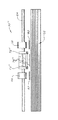
図1は、その一部を除去したハウジングを有する本発明の給紙装置の第1の実施態様に組み入れたプリンタの斜視図である。当業者は本発明の開示内容がその範囲から逸脱することなくプリンタ、プロッタ、複写機、ファクシミリ装置及び他のハードコピー媒体制御装置に使用できることを認識するであろう。
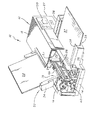
図1に示すように、前記プリンタ10は紙制御装置15及び印刷組立体20を包含するハウジング組立体12を具備する。前記ハウジング組立体12はそこから上方に突出する一対の枠壁18を有する略長方形の基台14から成っている。略L字状の断面形状及びリップを有する支持部(図示せず)が前記各枠壁18の間に延伸し、供給組立体30を支持する。
【0018】
前記紙制御装置15及び印刷組立体20の構成要素は前記基台14、各環枠壁18及び支持部に固定される。カバー16は前記基台14に着脱可能に取り付けられてその内部への出入を許容する。堆積体32(以後、「スタック」と称する)における紙シート(以後、単に「紙」と称する)又は他のプリント媒体を包含するトレー34は前記プリンタ10の内に着脱可能に取り付けられる。
収容トレー36は前記基台14に固定される。前記収容トレー36は印刷された前記紙を収容するために前記カバー16の前方にある開口部から外方に突出する。前記各紙は前記紙制御装置15によって、前記紙が前記収容トレー36に向けて前進するにつれて前記印刷組立体20がインクを前記紙の上に付着させる印刷領域を通して移動される。
【0019】
当該技術分野で周知であり、且つ前記Jackson 特許で詳細に記述され、ここにその開示内容が組み入れられているように、前記印刷組立体20は前記印刷領域を通してキャリッジロッド23の上で前後に走行するプリントヘッド・キャリッジ22を具備する。
前記プリントヘッド・キャリッジ22は駆動ワイヤスプール29によりキャリッジモータに連結された駆動ワイヤ24により、当業者に周知の方法で、双方向に移動する。前記プリントヘッド・キャリッジ22は、その底部にプリントヘッドを有する一個以上のプリントヘッド・カートリッジ(図示せず)を具備する。
【0020】
前記プリントヘッド・カートリッジは、可撓性を有する電気相互接続ストリップ26により、図1に破線で示したマイクロプロセッサ130 に接続される。前記マイクロプロセッサ130 はキャリッジモータ(図示せず)を制御する。制御パネル27は、前記印刷組立体20の作動に関係する種々のオプションの選択のための前記マイクロプロセッサ130 に電気的に結合される。
このような制御作動は当該技術分野で既知で入手可能なマイクロプロセッサによって与えられる。前記印刷組立体20の構造及び作動は本発明を全く構成せず、従って、以後詳細に記述しないことにする。更に、前記マイクロプロセッサ130 は図1で前記制御パネル27の近くに図示されているが、仮に必要な電気接続が前記プリンタ10の他の要素に対してなされるならば、前記マイクロプロセッサ130 が前記ハウジング12内の別の場所に位置決め可能であることは当業者にとって明らかであろう。
【0021】
本発明の開示内容によれば、前記紙制御装置15は、一枚の前記紙を前記スタック32から取り出すための第1及び第2の取り出しタイヤ66,68、及びその後、前記スタック32を初期状態にリセットするためのキッカー装置70を具備する。前記キッカー装置70は幾つかの実施態様に関連して開示される。当業者は本発明の開示内容を組み入れる別の実施態様がその範囲から逸脱することなく実現されることを認識するであろう。
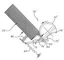
本発明の開示内容を利用するキッカー装置の第1の実施態様は図1、図2〜図6に示されている。図2〜図5はその作動サイクルの種々の段階における本発明のキッカー装置70の第1の実施態様の簡略化された側面図を示す。図6は本発明の開示内容を取り入れたキッカー装置70の第1の実施態様の簡略化された正面図である。
【0022】
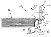
図1〜図6に示すように、第1の実施態様において、前記キッカー装置70は第1の取り出しタイヤ66と第2の取り出しタイヤ68との間で取り出し軸64に取り付けられたキッカーカム72を具備する。図2〜図5の各側面図に示されているように、前記キッカーカム72は三日月に似た半円D字形状を有する。前記キッカーカム72はプラスチック材又は他の適当な材料から形成される。
前記カム72は前記キッカー76に係合するように適合されたカム面の一方端部に突起73を有する。前記カム面は他方端部74まで全体的に弓形である。以下に詳述するように、前記キッカー76がもはやそれと接触しない位置、即ち、前記カム面74の他方端部の位置まで前記キッカーカム72が回転すると、前記カム面の弓形は前記キッカー76の原点位置への円滑な復帰を容易にする。
【0023】
この実施態様において、前記キッカー76は略平面状構造のプラスチック片である。その端部近傍で、前記キッカー76はそれらの間に溝78を画成する上方に突出する部分77及び79によって略U字形を成す。前記溝78はその回転サイクルの一部の期間中に前記キッカーカム72と係合するように適合される。前記上方に突出する部分77,79は、以下に詳述するように、前記スタック32上の前記紙に係合し、それをリセットする。
前記キッカー76は旋回点75を前記プリンタ10の枠壁18、基台14、又は他の強固な構造体に旋回可能に取り付けられ、キッカーばね80により付勢されている。前記キッカーばね80の一方端部は前記キッカー76の遠方の他方端部に取り付けられ、該キッカーばね80の他方端部は前記ハウジング組立体12に固定される。
【0024】
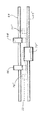
分離パッド82は第2のばね84の影響を受けて上下に移動し、前記各取り出しタイヤ66,68によって前記スタック32から引き外されるにつれ、充分な分離力が前記紙に付与されることを保証する(図6を参照)。前記スタック32は更に第3のばね86により上方に付勢される。
図2は前記キッカーばね80によって前方に付勢された前記キッカー76により原点位置にある本発明のキッカー装置70の第1の実施態様を示す。作動中、前記マイクロプロセッサ130 の制御による取り出しサイクルの開始後、前記各取り出しタイヤ66,68 及び前記キッカーカム72が回転を始める。
【0025】
図3は前記取り出しサイクルの開始後の本発明のキッカー機構70の第1の実施態様を示す。前記キッカーカム72は前記キッカー76を第2の位置まで押し出して前記紙を前記各取り出しタイヤ66,68 (図2〜図3に図示せず)に接触させることを可能にする。前記紙の前記スタック32は前記軸64から離れて動作する通常のスタック高さ制御カム機構(図示せず)により前記第3のばね86の影響を受けて、前記各取り出しタイヤ66,68 に接触するように上昇することが許容されている。
前記分離パッド82は前記各取り出しタイヤ66,68 によって押し下げられている。前記キッカーカム72の外周辺は前記キッカー76を前記第2の位置に維持する。
前記各取り出しタイヤ66,68 は、当該技術分野で周知のように前記各取り出しタイヤ66,68 が前記紙の上を回転すると、該紙を移動させるに有効な摩擦係数(例えば、前記紙に対し1.6 以下)を有する。前記分離パッド82は通常前記紙に対し1.0 以下の摩擦係数を有し、それによって前記スタック32から一枚の前記紙の取り出しを補助する。
【0026】
図4は前記紙が前記キッカー76の上を移動して給紙ロールにより取り出されるときの本発明のキッカー機構70の第1の実施態様を示す。前記各取り出しタイヤ66,68 及び前記キッカーカム72は反時計方向の回転を続け、前記紙の前記スタック32は前記スタック高さ制御カム機構(図示せず)によって下降される。前記キッカー76は一枚の前記紙がその上を完全に通過するまで前記キッカーカム72による押し出しが継続される。
前記一枚の前記紙が通過してから、前記キッカーカム72は前記他方端部74が前記キッカー76と接触する点を越えて回転する。前記キッカー76は前記キッカーばね80の荷重によって、前記分離パッド82に残存する全ての前記紙を前記スタック32に押し戻す。
【0027】
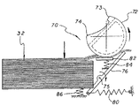
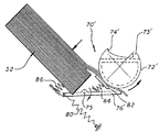
図5は前記キッカー76以外の全ての部材が前記原点位置に戻っている本発明のキッカー機構70の第1の実施態様を示す。しかる後、前記キッカー機構70は前記キッカーカム72及びキッカー76が前記原点位置に戻り、その初期状態になる。図2の実施態様は前記媒体の水平スタックに特に適するが、図7〜図13の第2の実施態様は前記媒体の傾斜スタックを使用するよう設計されている。
前記スタック32を傾斜させる理由は前記プリンタ10の占有面積を減少させることにある。しかしながら、前記スタック32が傾けられると、更に多数の前記紙が重力のために前記分離パッド82上に残る。残念ながら、前記紙を前記分離パッド82から該分離パッドを損傷させずに、取り除くに充分に強い前記キッカーばね80を巧みに処理することは困難である。
【0028】
図7はその一部を除去したハウジングを有する本発明の給紙装置の第2の実施態様を取り入れたプリンタの斜視図である。この給紙装置は、以下に詳述するように、供給トレー34がハウジング組立体12に対して傾斜し、且つキッカー機構70’が図1の前記キッカー機構70と異なること以外は、図1のものと本質的に同一であることを注目されたい。
【0029】
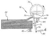
図8〜図13はその作動サイクルの種々の段階における本発明のキッカー機構70' の第2の実施態様の簡略化された側面図を示す。前記キッカー機構70' の第2の実施態様は、カム面の他方端部74' の延伸部分が異なるだけで第1の実施態様と同じである。
先ず、前記キッカー機構70' の第2の実施態様の作動は、図8〜図11に示したように、第1の実施態様のキッカー機構70と同じである。一枚の前記紙がキッカー76' の上を通過した後、キッカーカム72' が図12に示すように逆回転し、前記キッカーカム72の延伸した前記他方端部74が前記キッカー76を押し戻して前記キッカー76を前記スタック32に対して押し上げる。最後に、図13に原点位置にある前記キッカー機構70' が示されている。
【0030】
図14〜図17はその作動サイクルの種々の段階における本発明のキッカー機構70''の第3の実施態様の簡略化された側面図を示す。図18は本発明のキッカー機構70''の第3の実施態様の正面図である。この設計は分離を行うために千鳥状に入れ子されたロールを使用する逆回転ロール設計である。自動給紙装置に逆回転ロールを使用することは全く普通の概念である。
しかしながら、逆回転ロールの使用による主な問題点は、各ロール間の力がある範囲内に維持することが困難であり、モータのトルクが高速作動で低く保とうとする場合、トルクリミッタを使用しなければならないことにある。更に、前記キッカー機構70''はこれらの使用に関連して信頼性が向上する可能性があるにもかかわらず、形状寸法の制約のためこれらのシステムに採用されない。
【0031】
図14〜図18に示したように、本発明の第3のキッカー機構70''は、第1及び第2のD字状の取り出しタイヤ66,68の間に取り付けられた分離ロール72''を具備する。前記分離ロール72''はプラスチックから成り、約1.0 の前記紙に対する摩擦係数を有する。第1及び第2の可撓性キツカー76''及び77''は、図18の正面図で破線で示したように、前記第1及び第2の取り出しタイヤ66,68の外側で前記分離ロール72''を有するキッカー軸65''に配設されている。
前記各可撓性キッカー76'',77''は、マイラー(du pont 社の商標名 Mylar)または他の適当な材料から成り、その厚さは約 0.4mmである。前記各可撓性キッカー76'',77''は以下に詳述するように、前記スタック32を有効にリセットするのに十分に長く形成される。前記各可撓性キッカー76'',77''は可撓性を有するように形成され、前記紙の前記スタック32が前記各取り出しタイヤ66,68の下に配置される。
【0032】
第3の実施態様の作動は図14〜図17に関連して最も良く図示されている。図14はその原点位置で初期設定された前記第3のキッカー機構70''を示す。前記各取り出しタイヤ66,68及び前記分離ロール72''は取り出しサイクル当たり1回転正確に回転駆動される。前記取り出しサイクルの開始時に持ち上げられて前記各取り出しタイヤ66,68に差し出され、前記取り出しサイクルが完了する前に下げられる。
図15は反時計方向に回転して上方にある数葉の前記紙を上昇した前記スタック32から前記分離領域に引き寄せている前記各取り出しタイヤ66,68を示す。同時に、前記分離ロール72''も反時計方向に回転して、最上部の前記紙33を除く全ての前記紙が前記各可撓性キッカー76'',77''を越えることを阻止する。この分離ロール72''の反時計方向の回転は前記各可撓性キッカー76'',77''を極端に屈曲させる。
【0033】
図16は既に下降している前記スタック32と、同じ方向に回転し続けている前記各取り出しタイヤ66,68及び前記分離ロール72''を示す。前記分離ロール72''が余分の前記紙の供給を阻止し続けている間に、前記各可撓性キッカー76'',77''は一枚の前記紙33がその上を通過すると、前記一枚の前記紙33によって後方に屈曲される。
最後に、図17は前記原点位置に戻っている全て構成要素を示す。前記一枚の紙33によって解放された前記各可撓性キッカー76'',77''は、真直ぐになり、余分な前記紙を前記分離領域から前記スタック32上に、そして初期設定位置に押し戻す。
【0034】
図18に示すように、前記紙33は前記各ロールの周りに屈曲すると分離ばねとして使用される。これは高価なトルクリミッタ及び分離力に関連する厳しい許容誤差の必要性を緩和させる。更に、前記分離ロール72''にトルクリミッタがないので、前記各可撓性キッカー76'',77''は前記分離領域を一掃するために使用される。これは前記紙の前記スタックを傾斜させることを可能にし、前記傾斜が前述した装置の占有面積を減少させる。
【0035】
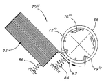
図19〜図24はその作動サイクルの種々の段階における本発明のキッカー機構70''' の第4の実施態様の簡略化された側面図を示す。図25は本発明のキッカー機構70''' の第4の実施態様の正面図である。図19〜図25に示したように、本発明のキッカー機構70''' は第1及び第2の各取り出しタイヤ66,68の間で取り出し軸64に取り付けられた第1及び第2のキッカータイヤ72''' 及び73''' を具備する。
複数のプラスチックキッカー要素76''' が前記第1及び第2のキッカータイヤ72''' 及び73''' の間に配設される。前記各キッカー要素76''' はピン81''' の周りを旋回運動のために取り付けられたブレードであり、運動リミツタ79''' に接触するまで、重力の影響を受けて自由に落下する。前記運動リミツタ79''' は、図19〜図24に示したように前記キッカー要素76''' の運動の範囲を制限するように配設されたプラスチックまたは金属の釘、ピン、または突起である。
【0036】
図19は始動位置にある前記キッカー機構70''' を示す。この実施のための原点位置は存在しない。前記軸64が回転すると、前記各キッカー要素76''' が中心を外れて回転し、前記軸64が反時計方向に回転すると、(図19〜図22に示したように)押上げられて邪魔にならないところに退避し、前記軸64が時計方向に回転すると、(図23及び図24に示すように)落下して前記紙を押す。前記分離パッド82は上下に移動して充分な分離力を保証し、ばね84によって上方に付勢される。前記スタック32も上方に付勢されるが、該スタック32は前記取り出しサイクルの開始時に持ち上げられ、その完了前に下げられる。
【0037】
図20は前記取り出しサイクル開始後の前記キッカー機構70''' を示す。前記各紙は順方向(反時計方向)回転で前記各キッカー要素76''' を押上げ、邪魔にならないところに退避させる。前記紙の前記スタック32は前記各取り出しタイヤ66,68 に接触するように持ち上げられ、最上部の数葉の前記紙が前記分離領域に引き込まれている。図21は更に順方向に回転した前記軸64を示し、前記各キッカー要素76''' の運動を説明するのに役立つ。
図22は前記最上部の前記紙が完全に送られた後の前記キッカー機構70''' を示す。図23は回転方向を逆にしている前記キッカータイヤ72''' 及び落下して前記紙を前記分離領域から押し出している前記キッカー要素76''' を示す。図24は前記分離領域から完全に蹴り出され前記紙の前記スタック32上にある前記紙を示す。
【0038】
前述したように、本発明はここに特定の適用に対する特定の実施態様に関して記述した。当業者及びここ提案されている開示内容を利用できる者は、本発明の範囲内で別の変更、適用、実施態様、及び本発明の有用な別の分野を夫々認識するであろう。例えば、本発明はここに示した付勢装置に限定されない。当業者は前記キッカー要素が付勢ばねに代わり固有のばね力で(旋回可能に取り付ける代わりに)強固に取り付けることができることを認識するであろう。なお、本発明による自動給紙装置の各実施態様を列挙すれば概ね以下の通りである。
【0039】
1) 堆積体からシート状媒体を選択的に移動させるための軸に取り付けられた取り出しタイヤと、前記堆積体上の前記媒体を第1位置に保持するキッカーと、前記キッカーを第1位置から第2位置に偏倚させるために前記軸に取り付けられたカムとを具備して成ることを特徴とする自動給紙装置。
【0040】
2) 上記1)の自動給紙装置であって、前記カムが第1方向の回転サイクルの一部の期間中に前記キッカーを偏倚させ、前記カムが第2方向の回転位置にあるとき前記キッカーを解放するように適合することを特徴とする自動給紙装置。
【0041】
3) 上記2)の自動給紙装置であって、前記カムが第2方向に回転すると、前記キッカーを前記堆積体に向けて押す付けるように形成されることを特徴とする自動給紙装置。
【0042】
4) 上記1)の自動給紙装置であって、前記キッカーが枠体に旋回可能に取り付けられていることを特徴とする自動給紙装置。
【0043】
5) 上記4)の自動給紙装置であって、前記キッカーの他方端部がばねにより前記枠体に取り付けられていることを特徴とする自動給紙装置。
【0044】
6) 上記5)の自動給紙装置であって、前記キッカーの一方端部が前記カムと係合することを特徴とする自動給紙装置。
【0045】
7) 上記1)の自動給紙装置であって、前記カムが略D字状に形成されていることを特徴とする自動給紙装置。
【0046】
8) 上記1)の自動給紙装置であって、前記カムがその端縁に沿って隆起部を具備することを特徴とする自動給紙装置。
【0047】
9) 上記8)の自動給紙装置であって、前記カムが弓形の断面形状を有することを特徴とする自動給紙装置。
【0048】
10) 上記1)の自動給紙装置であって、前記シート状の媒体が分離ばねとして機能することを特徴とする自動給紙装置。
【0049】
11) 上記1)の自動給紙装置であって、更に、前記軸を逆回転させ、それにより前記キッカーをして前記堆積体上に前記媒体を押し戻させる前記軸を逆転させる手段を具備して成ることを特徴とする自動給紙装置。
【0050】
12) 上記1)の自動給紙装置であって、前記キッカーが前記軸に取り付けられた前記第1及び第2のキッカータイヤの間に取り付けられた複数のブレードを具備することを特徴とする自動給紙装置。
【0051】
【発明の効果】
以上、記述した本発明の自動給紙装置は次に記すような新規な効果を奏するものである。即ち、本発明の自動給紙装置は、前記堆積体からシート状媒体を選択的に移動させるための前記軸に取り付けられた前記取り出しタイヤと、前記堆積体上の前記媒体を第1位置に保持する前記キッカーと、前記キッカーを第1位置から第2位置に偏倚させるために前記軸に取り付けられた前記カムとを具備して成るので、前記カムは回転サイクルの一部の期間中に前記堆積体上の前記媒体に係合し、更に前記キッカーを第2の位置まで押し出して前記媒体を前記各取り出しタイヤに接触させることが可能になり、更に反時計方向の回転を続け、前記一枚の媒体が前記キッカー上を完全に通過してから、前記キッカーの原点位置復帰力によって分離パッド上に残存する全ての前記媒体を前記堆積体に押し戻すことが可能になった。
【0052】
従って、本発明の自動給紙装置は従来装置のような前記ローラと前記パッドとの間の分離領域における前記媒体の多数同時送りの発生を防止し、コンパクトな構造で廉価なキッカー装置によって前記媒体の先端縁とプリントの第1行との逸れを最小にする自動給紙装置を提供することが可能になった。
【図面の簡単な説明】
【図1】本発明の自動給紙装置の第1の実施態様を組み込んだプリンタの斜視図である。
【図2】図1において原点位置にあるキッカー装置の側面図である。
【図3】図1において取り出しサイクルの開始後のキッカー装置の側面図である。
【図4】図1において紙がキッカー装置の上を移動して給紙ロールにより取り出されるときのキッカー装置の側面図である。
【図5】図7においてキッカー装置以外の全ての部材が原点位置に戻っている状態のキッカー装置の側面図である。
【図6】図1におけるキッカー装置の正面図である。
【図7】本発明の自動給紙装置の第2の実施態様を組み込んだプリンタの斜視図である。
【図8】図7において原点位置にあるキッカー装置の側面図である。
【図9】図7において取り出しサイクルの開始後のキッカー装置の側面図である。
【図10】図7において紙がキッカー装置の上を移動して給紙ロールにより取り出されるときのキッカー装置の側面図である。
【図11】図7においてキッカー装置以外の全ての部材が原点位置に戻っている状態のキッカー装置の側面図である。
【図12】図7においてキッカーカムの逆回転によってキッカーが紙をスタック上に押し戻しているキッカー装置の側面図である。
【図13】図7においてキッカー装置も原点位置に戻っている状態のキッカー装置の側面図である。
【図14】本発明の自動給紙装置の第3の実施態様において原点位置にあるキッカー装置の側面図である。
【図15】本発明の自動給紙装置の第3の実施態様において取り出しサイクルの開始後のキッカー装置の側面図である。
【図16】本発明の自動給紙装置の第3の実施態様において紙がキッカー装置の上を移動して給紙ロールにより取り出されるときのキッカー装置の側面図である。
【図17】本発明の自動給紙装置の第3の実施態様において原点位置に戻っている状態のキッカー装置の側面図である。
【図18】本発明の自動給紙装置の第3の実施態様におけるキッカー装置の正面図である。
【図19】本発明の自動給紙装置の第4の実施態様において始動位置にあるキッカー装置の側面図である。
【図20】本発明の自動給紙装置の第4の実施態様において取り出しサイクルの開始後のキッカー装置の側面図である。
【図21】本発明の自動給紙装置の第4の実施態様において更に順方向に回転するキッカー装置の側面図である。
【図22】本発明の自動給紙装置の第4の実施態様において最上部の紙が完全に送られた後のキッカー装置の側面図である。
【図23】本発明の自動給紙装置の第4の実施態様において逆転するキッカータイヤと紙を分離領域から押し戻しているキッカー要素を示すキッカー装置の側面図である。
【図24】本発明の自動給紙装置の第4の実施態様において分離領域からスタック上に完全に蹴り出され紙を示すキッカー装置の側面図である。
【図25】本発明の自動給紙装置の第4の実施態様における本発明の自動給紙装置の第4の実施態様におけるキッカー装置の正面図である。
【符号の説明】
15 自動給紙装置
32 スタック
64 軸
66 取り出しタイヤ
68 取り出しタイヤ
72 カム
76 キッカー
80 ばね[0001]
BACKGROUND OF THE INVENTION
The present invention relates to a hard copy medium control apparatus. More particularly, the present invention relates to a paper control device and method in a sheet-like paper supply device used in a printer, a plotter, a copying machine, a facsimile machine or the like.
[0002]
[Prior art]
Paper feeders for hard copy control devices are well known in the art. In an automatic sheet printer, a stack of sheet-like paper (hereinafter simply referred to as “paper”) (hereinafter referred to as “stack”) is usually a printer, plotter, copier, facsimile using a roller assembly or other mechanism. Automatically supplied to the device. An important function of the automatic paper feeder is to control the amount of deviation between the leading edge of the paper and the first line of the print contained on the paper, that is, the deviation between the paper and the print.
A small amount of deflection between the paper and the print can also cause distortion in the print, and a larger amount of deflection can cause the print to bend, resulting in uneven print quality or jamming of the paper in the printer. The deflection generally occurs when the paper is fed into or removed from the stack of paper in a supply tray. Accordingly, it is desirable to minimize the amount of deflection between the paper and the printing mechanism before the paper is removed and printed thereon.
[0003]
Conventional printing devices use various techniques and devices to minimize the deflection. Some conventional devices generate a curve in the paper by pushing the paper sheet into a pair of stall rollers, and minimize the amount of deflection by making the leading edge of the paper parallel to the roller pair. Thereafter, the roller is actuated to advance the paper into the printing area.
Such a technique requires a clutch mechanism that stalls the roller long enough to feed the paper into the nip area between the rollers. Furthermore, this technique requires that the paper is large enough to correct the deflection and small enough so that the paper does not pop out of the nip area between the stalled rollers, so that the paper is curved. , Requires precise control of the paper.
[0004]
Other devices in the prior art use tapered rollers that point the paper against the reference wall, align it with the reference wall, and remove any deviations before printing. This technique requires large flat surfaces and fairly slow rollers in the area of the roller assembly. In addition, other devices do not have any deflection correction mechanism and rely entirely on the accurate supply of the paper to the roller assembly.
[0005]
In addition to minimizing the deflection, the paper feeder must maintain precise control of each paper from the time the paper is removed from the stack until it is discharged out of the device. The paper feeding device such as a conventional ordinary printer, plotter, copying machine, facsimile machine, etc. takes out the paper from the stack, sends the paper to a printing mechanism, feeds the paper, and feeds the printed paper. Separate motors and transmissions are used for discharging.
Such paper feeders have complex timing mechanisms that often obstruct the carriage drive motor or require triggering means such as solenoids. The multiple motors and other electrical components increase the cost of the paper feed mechanism. Further, the complex paper feeder increases the time required to pass a page through the paper feeder, as well as the opportunity for the paper jam and misalignment error.
[0006]
Necessary technology for a paper feeder with a minimum control device was granted a patent to Jackson et al. On July 13, 1993 "Method and Appratus for Paper"
Proposed to some extent by US Pat. No. 5,226,743 entitled “Control in a Printer”, the disclosure of which is hereby incorporated by reference.
The document selectively contacts only a single motor drive mechanism, a frame, a platen, a roller assembly for advancing the paper on the platen, and one edge of the paper. An apparatus for controlling the paper in a printer mechanism comprising a kicker element for pushing the paper forward when released from a roller assembly is disclosed and included in the claims.
[0007]
Despite the various advantages associated with the device described in the cited patent, it is technically further in a paper feeding device that allows reliable and precise control of the paper through the device with low cost and high production. There remains a need for improvement. This need is especially true for the role of the kicker.
The kicker is used to assist the movement of the paper in the paper feeder. For example, the kicker is used to assist in moving printed pages into a storage tray, as disclosed in the Jackson patent. In that variation, the kicker is used to reset the paper stack in the paper feeder so that printing of each paper starts from a known initial state during a printing operation.
[0008]
In recent years, various sheet feeding apparatuses are known. Usually, paper feeding is performed using a roller on the top surface of the paper and a friction pad on the bottom surface of the paper. In this case, the kicker assists the movement of the paper from the nip area between the roller and the pad and prevents multiple simultaneous feeds.
[0009]
[Problems to be solved by the invention]
However, commercially available kicker mechanisms require a large number of parts and are therefore expensive and require considerable space. Thus, there remains a need for an inexpensive and effective kicker mechanism for the next generation of hardcopy devices.
[0010]
The present invention solves the above-mentioned problems of the prior art, and provides an automatic paper feeder that minimizes the deviation between the leading edge of the medium and the first line of the print by a low-cost kicker device having a compact structure. It is the purpose.
[0011]
[Means for Solving the Problems]
Such an object of the present invention is to provide a take-out tire attached to a shaft for selectively moving a sheet-like medium from a deposit, a kicker that holds the medium on the deposit in a first position, and the kicker. It is achieved by an automatic paper feeder comprising a cam attached to the shaft for biasing from a first position to a second position.
[0012]
[Action]
The need in the art is addressed by the paper feeder of the present invention. In general, the apparatus of the present invention comprises a pick-up device that selectively moves a sheet of media from a stack. Several embodiments of kickers that serve to hold the media on the stack are disclosed. In a first embodiment, a cam is coupled to the pick-up device to move the kicker from a first position holding the medium on the stack to a second position where the medium can move through the pick-up device. Bias.
In a particular implementation of the first embodiment, the take-out device comprises a frame and a shaft attached to the frame for rotational movement relative to the frame. The take-out device comprises a take-out tire attached to the shaft and adapted to rotate therewith. The kicker is attached to the frame and holds the medium on the stack in a first position. The cam is adapted to bias the kicker during a first part of a rotation cycle and release the kicker when the cam is in a second rotational position.
[0013]
In a second embodiment, the cam is contoured to provide a projecting end that engages the kicker when the cam rotates in reverse. This is particularly well suited to printers that use the tilted media tray to cause the kicker to push the remaining media on the separation roll back onto the stack.
[0014]
In a third embodiment, the kicker is mounted on a shaft with a separation roll. In a particular implementation of this embodiment, the kicker is a piece of flexible plastic that flexes as the shaft rotates and engages the stack. After the kicker rotates around the axis, it pushes the medium remaining on the separation roll back onto the stack.
A particularly novel aspect of this implementation consists in using the medium as a separation spring between each take-out tire attached to the first axle and the separation roll attached to the second axle. The separation spring effect is to facilitate separation of each media sheet from other media sheets on the stack.
[0015]
Finally, the fourth embodiment discloses having a plurality of small gravity-actuated kickers mounted between two take-off tires. The kicker is adapted to leave out of the way when the take-out tire rotates in the first direction, and to fall into place when the take-out tire rotates in reverse and push the media back into the stack. The
[0016]
DETAILED DESCRIPTION OF THE INVENTION
An embodiment of the automatic paper feeder of the present invention will be described in detail below with reference to the accompanying drawings. While the present invention is described herein by way of example for a particular application, it should be understood that the invention is not limited thereto. Those skilled in the art and those who have access to the proposed disclosure will each recognize other modifications, applications, embodiments, and other useful areas of the invention within the scope of the invention.
[0017]
FIG. 1 is a perspective view of a printer incorporated in a first embodiment of a paper feeding device of the present invention having a housing with a part thereof removed. Those skilled in the art will recognize that the present disclosure can be used in printers, plotters, copiers, facsimile machines, and other hardcopy media control devices without departing from the scope thereof.
As shown in FIG. 1, the
[0018]
The components of the
The
[0019]
As is well known in the art and described in detail in the Jackson patent, the disclosure of which is incorporated herein, the
The
[0020]
The printhead cartridge is connected by a flexible
Such control operations are provided by microprocessors known and available in the art. The structure and operation of the
[0021]
According to the disclosure of the present invention, the
A first embodiment of a kicker device that utilizes the disclosure of the present invention is illustrated in FIGS. 2-5 show simplified side views of a first embodiment of the
[0022]
As shown in FIGS. 1 to 6, in the first embodiment, the
The
[0023]
In this embodiment, the
The
[0024]
The
FIG. 2 shows a first embodiment of the
[0025]
FIG. 3 shows a first embodiment of the
The
Each take-out
[0026]
FIG. 4 shows a first embodiment of the
After the sheet of paper has passed, the
[0027]
FIG. 5 shows a first embodiment of the
The reason for tilting the
[0028]
FIG. 7 is a perspective view of a printer incorporating a second embodiment of the paper feeding device of the present invention having a housing with a part thereof removed. This paper feeder is shown in FIG. 1 except that the
[0029]
8-13 show simplified side views of a second embodiment of the kicker mechanism 70 'of the present invention at various stages of its operating cycle. The second embodiment of the kicker mechanism 70 'is the same as the first embodiment except that the extended portion of the other end 74' of the cam surface is different.
First, the operation of the second embodiment of the kicker mechanism 70 'is the same as that of the
[0030]
FIGS. 14-17 show simplified side views of a third embodiment of the
However, the main problem with the use of reverse rotating rolls is that it is difficult to maintain the force between each roll within a certain range. There is something that must be done. Furthermore, the kicker mechanism 70 '' may not be employed in these systems due to geometry constraints, despite the potential for increased reliability associated with their use.
[0031]
As shown in FIGS. 14-18, the third kicker mechanism 70 '' of the present invention is provided with a separating roll 72 '' mounted between the first and second D-shaped take-out
Each of the
[0032]
The operation of the third embodiment is best illustrated with reference to FIGS. FIG. 14 shows the third kicker mechanism 70 '' initialized at the origin. Each of the take-out
FIG. 15 shows the take-out
[0033]
FIG. 16 shows the
Finally, FIG. 17 shows all components returning to the origin position. Each
[0034]
As shown in FIG. 18, when the
[0035]
19-24 show simplified side views of a fourth embodiment of the kicker mechanism 70 '''of the present invention at various stages of its operating cycle. FIG. 25 is a front view of the fourth embodiment of the
A plurality of plastic kicker elements 76 '''are disposed between the first and second kicker tires 72''' and 73 '''. Each kicker element 76 '''is a blade mounted for pivotal movement around a pin 81''' and falls freely under the influence of gravity until it contacts the movement limiter 79 ''' . The motion limiter 79 '''is a plastic or metal nail, pin, or protrusion arranged to limit the range of motion of the kicker element 76''' as shown in FIGS. is there.
[0036]
FIG. 19 shows the kicker mechanism 70 '''in the starting position. There is no origin position for this implementation. When the
[0037]
FIG. 20 shows the
FIG. 22 shows the kicker mechanism 70 '''after the topmost paper has been completely fed. FIG. 23 shows the
[0038]
As noted above, the present invention has been described herein with reference to a particular embodiment for a particular application. Those skilled in the art and those who have access to the proposed disclosure will each recognize other modifications, applications, embodiments, and other useful areas of the invention within the scope of the invention. For example, the present invention is not limited to the biasing device shown here. One skilled in the art will recognize that the kicker element can be rigidly attached (instead of pivotally attached) instead of a biasing spring with an inherent spring force. The embodiments of the automatic paper feeder according to the present invention are listed as follows.
[0039]
1) A take-out tire attached to a shaft for selectively moving the sheet-like medium from the deposit, a kicker that holds the medium on the deposit in a first position, and the kicker from a first position to a first An automatic paper feeder comprising a cam attached to the shaft for biasing to two positions.
[0040]
2) The automatic paper feeder of 1) above, wherein the cam biases the kicker during a part of a rotation cycle in the first direction, and the kicker is in the rotation position in the second direction. An automatic paper feeder characterized by being adapted to release.
[0041]
3) The automatic paper feeder according to 2), wherein the automatic paper feeder is formed so as to press the kicker toward the deposit when the cam rotates in the second direction.
[0042]
4) The automatic paper feeder according to 1) above, wherein the kicker is pivotably attached to a frame.
[0043]
5) The automatic paper feeder according to 4) above, wherein the other end of the kicker is attached to the frame body by a spring.
[0044]
6) The automatic paper feeder according to 5) above, wherein one end of the kicker is engaged with the cam.
[0045]
7) The automatic paper feeder according to 1) above, wherein the cam is formed in a substantially D shape.
[0046]
8) The automatic paper feeder according to 1) above, wherein the cam includes a raised portion along an edge thereof.
[0047]
9) The automatic paper feeder according to 8) above, wherein the cam has an arcuate cross-sectional shape.
[0048]
10) The automatic paper feeder according to 1) above, wherein the sheet-like medium functions as a separation spring.
[0049]
11) The automatic paper feeder of 1) further comprising means for reversing the shaft to reversely rotate the shaft, thereby causing the kicker to push the medium back onto the deposit. An automatic paper feeder characterized by comprising.
[0050]
12) The automatic paper feeder of 1) above, wherein the kicker comprises a plurality of blades attached between the first and second kicker tires attached to the shaft. Paper feeder.
[0051]
【The invention's effect】
As described above, the automatic sheet feeder according to the present invention has the following novel effects. That is, the automatic paper feeder of the present invention holds the take-out tire attached to the shaft for selectively moving a sheet-like medium from the deposit and the medium on the deposit in a first position. The kicker and the cam attached to the shaft for biasing the kicker from a first position to a second position, so that the cam is deposited during a portion of a rotational cycle. Engaging the medium on the body, further pushing the kicker to the second position to allow the medium to contact each of the take-out tires, and continue to rotate counterclockwise, After the medium has completely passed over the kicker, all of the medium remaining on the separation pad can be pushed back to the deposit by the return-to-origin force of the kicker.
[0052]
Accordingly, the automatic paper feeder of the present invention prevents the simultaneous feeding of a large number of the media in the separation region between the roller and the pad as in the conventional device, and the medium is provided by an inexpensive kicker device with a compact structure. It has become possible to provide an automatic paper feeder that minimizes the deviation between the leading edge of the print and the first line of the print.
[Brief description of the drawings]
FIG. 1 is a perspective view of a printer incorporating a first embodiment of an automatic paper feeder of the present invention.
FIG. 2 is a side view of the kicker device at the origin position in FIG.
FIG. 3 is a side view of the kicker device after the start of the take-out cycle in FIG. 1;
4 is a side view of the kicker device when the paper moves on the kicker device in FIG. 1 and is taken out by a paper feed roll. FIG.
FIG. 5 is a side view of the kicker device in a state where all members other than the kicker device in FIG. 7 have returned to the origin position.
6 is a front view of the kicker device in FIG. 1. FIG.
FIG. 7 is a perspective view of a printer incorporating a second embodiment of the automatic paper feeder of the present invention.
FIG. 8 is a side view of the kicker device at the origin position in FIG. 7;
FIG. 9 is a side view of the kicker device after the start of the take-out cycle in FIG.
FIG. 10 is a side view of the kicker device when the paper moves on the kicker device and is taken out by a paper feed roll in FIG. 7;
11 is a side view of the kicker device in a state in which all members other than the kicker device in FIG. 7 have returned to their original positions.
12 is a side view of the kicker device in which the kicker pushes the paper back onto the stack by the reverse rotation of the kicker cam in FIG. 7;
13 is a side view of the kicker device in FIG. 7 in a state where the kicker device is also returned to the origin position.
FIG. 14 is a side view of the kicker device at the origin position in the third embodiment of the automatic paper feeder of the present invention.
FIG. 15 is a side view of the kicker device after the start of the take-out cycle in the third embodiment of the automatic paper feeder of the present invention.
FIG. 16 is a side view of the kicker device when the paper moves on the kicker device and is taken out by the paper feed roll in the third embodiment of the automatic paper feeder of the present invention.
FIG. 17 is a side view of the kicker device in a state in which the automatic paper feeder of the present invention is returned to the origin position in the third embodiment.
FIG. 18 is a front view of a kicker device according to a third embodiment of the automatic paper feeder of the present invention.
FIG. 19 is a side view of the kicker device in the starting position in the fourth embodiment of the automatic paper feeder of the present invention.
FIG. 20 is a side view of the kicker device after the start of the take-out cycle in the fourth embodiment of the automatic paper feeder of the present invention.
FIG. 21 is a side view of a kicker device that further rotates in the forward direction in the fourth embodiment of the automatic paper feeder of the present invention.
FIG. 22 is a side view of the kicker device after the uppermost paper is completely fed in the fourth embodiment of the automatic paper feeder of the present invention.
FIG. 23 is a side view of the kicker device showing the kicker tire rotating in reverse and the kicker element pushing the paper back from the separation area in the fourth embodiment of the automatic paper feeder of the present invention.
FIG. 24 is a side view of the kicker device showing the paper that is completely kicked out of the separation area onto the stack in the fourth embodiment of the automatic paper feeder of the present invention.
FIG. 25 is a front view of a kicker device according to a fourth embodiment of the automatic paper feeder of the present invention in the fourth embodiment of the automatic paper feeder of the present invention.
[Explanation of symbols]
15 Automatic paper feeder
32 stacks
64 axes
66 tire
68 Take-out tire
72 cams
76 Kicker
80 spring
Claims (11)
堆積体から1枚ずつ媒体を選択的に移動させる第1手段と、
前記枠体に取り付けられて、前記堆積体の媒体を初期状態である第1位置に保持するキッカーを備えた、媒体を第1位置に保持するキッカー手段と、
前記第1手段に連結され、前記キッカー手段を前記第1位置から前記第1手段が媒体に接触する第2位置に偏倚させると共に、前記第2位置から前記第1位置に偏倚させる偏倚手段とを有し、
前記偏倚手段は、前記軸に取り付けられたキッカーカムを備え、前記キッカーカムは2つの端部を有し、第1の方向に回転するサイクルでは前記端部の1つによって前記キッカーを前記第1位置から前記第2位置に偏倚させると共に、前記端部の1つが前記キッカー手段と接触する点を越えた回転位置で前記キッカーを開放し、更に前記カムは前記カムが第2の方向に回転するとき前記堆積体に向けて前記端部の別な1つが前記キッカーを押し付け、キッカー手段を前記第1位置に押し戻すように形成されていることを特徴とする自動給紙装置。A frame with a rotating shaft attached thereto;
First means for selectively moving the medium one by one from the deposit;
Kicker means for holding the medium in the first position, comprising a kicker attached to the frame body and holding the medium of the deposited body in the first position which is an initial state ;
Biasing means coupled to the first means for biasing the kicker means from the first position to a second position where the first means contacts the medium and biasing from the second position to the first position; Have
The biasing means comprises a kicker cam attached to the shaft, the kicker cam having two ends, and in a cycle rotating in a first direction, the kicker is moved from the first position by one of the ends. Biasing to the second position and opening the kicker in a rotational position beyond the point where one of the ends contacts the kicker means, and the cam further moves when the cam rotates in the second direction. An automatic paper feeding device, wherein another one of the end portions presses the kicker toward the deposit and pushes the kicker means back to the first position .
前記枠体に取り付けられて回転する軸と、
前記軸に取り付けられて回転する取り出しタイヤと、
前記枠体に取り付けられて紙を初期状態である第1位置に保持する位置を備えたキッカーと、
前記軸に取り付けられた2つの端部を備えるキッカーカムとを有し、
前記キッカーカムは第1の方向に回転するサイクルでは前記端部の1つによって前記キッカーを偏倚させ、前記端部の1つが前記キッカー手段と接触する点を越えた回転位置で前記キッカーを開放し、前記カムが第2の方向に回転するとき前記カムは前記端部の別な1つが前記キッカーを堆積体に向けて押し付けるように形成されて前記キッカーが前記第1位置に戻ることを特徴とする自動給紙装置。A frame,
An axis attached to the frame and rotating;
A take-out tire attached to the shaft and rotating;
A kicker that is attached to the frame and has a position for holding the paper in a first position, which is an initial state ;
A kicker cam with two ends attached to the shaft;
The kicker cam biases the kicker by one of the ends in a cycle rotating in a first direction, and releases the kicker at a rotational position beyond the point where one of the ends contacts the kicker means ; When the cam rotates in the second direction, the cam is formed such that another one of the ends presses the kicker against the deposit, and the kicker returns to the first position. Automatic paper feeder.
キッカーによって堆積体の媒体を初期状態である第1位置に保持するステップと、
前記取り出しタイヤに連結された2つの端部を有するカムが第1の方向に回転すると前記端部の1つが前記キッカーを前記第1位置から前記取り出しタイヤが媒体に接触する第2位置に偏倚させるステップと、
前記キッカーを前記端部の別な1つで前記堆積体に押し付けるように前記カムを逆転させ、媒体を前記第1位置に押し戻すステップとを有する堆積体から媒体を移動させる方法。Selectively moving the medium one by one from the deposit by a takeout tire;
Holding the deposit medium in a first position, which is an initial state, by a kicker;
When a cam having two ends connected to the takeout tire rotates in a first direction, one of the ends biases the kicker from the first position to a second position where the takeout tire contacts the media . Steps,
Reversing the cam to press the kicker against the deposit at another one of the ends and moving the media out of the deposit with pushing the media back to the first position .
前記取り出し軸に取り付けられ、前記軸線周りに回転する一部の期間は堆積体の上部にあるシートを取り出すのを容易にし、前記軸線周りに逆回転する別な期間で堆積体から取り出された余分なシートを戻すのを容易にするタイヤ状のキッカーカムであって、
前記キッカーカムは外周に弓形の切り欠き部と、前記切り欠き部の端縁に隆起部を備えているキッカーカムと、
前記キッカーカムの下方にあって中央に溝を有し、前記キッカーカムが原点位置にあるとき、前記隆起部と係合するように前方に偏倚された旋回可能なキッカーと、
前記キッカーカムの前記隆起部によって堆積体から離れる方向に上部のシートが押されて取り出されるように、前記軸の一部の回転期間中は前記上部のシートと係合して前記上部のシートを取り出して、前記キッカーの方に移動させ、通過させる、前記取り出し軸上の前記キッカーの両側に取り付けられた対となる取り出しタイヤとを有し、
前記キッカーは前記取り出し軸が1回転を完了すると前記逆回転し、前記堆積体から引き出された余分なシートを押し戻すことを特徴とする堆積体から個々のシートを取り出す紙制御装置。A take-off shaft comprising an axis and mounted to rotate about said axis;
A portion of the period attached to the take-out shaft and rotating around the axis facilitates removal of the sheet on top of the deposit and an extra period removed from the deposit in another period of reverse rotation around the axis. A tire-like kicker cam that makes it easy to return the correct sheet,
The kicker cam has an arcuate notch on the outer periphery, and a kicker cam provided with a raised portion on the edge of the notch,
A pivotable kicker that is below the kicker cam and has a groove in the center, biased forward to engage the raised portion when the kicker cam is in the origin position;
The upper sheet is engaged with the upper sheet during the rotation of a part of the shaft so that the upper sheet is pushed out by the raised portion of the kicker cam in a direction away from the deposit. A pair of take-out tires attached to both sides of the kicker on the take-out shaft, which is moved toward and through the kicker,
The paper control device for taking out individual sheets from the deposit, wherein the kicker rotates backward when the take-out shaft completes one rotation, and pushes back an extra sheet pulled out from the deposit.
Applications Claiming Priority (2)
| Application Number | Priority Date | Filing Date | Title |
|---|---|---|---|
| US08/715,683 US5882004A (en) | 1996-09-18 | 1996-09-18 | Automatic sheet feeding mechanism |
| US715-683 | 1996-09-18 |
Publications (2)
| Publication Number | Publication Date |
|---|---|
| JPH1087093A JPH1087093A (en) | 1998-04-07 |
| JP3893199B2 true JP3893199B2 (en) | 2007-03-14 |
Family
ID=24875075
Family Applications (1)
| Application Number | Title | Priority Date | Filing Date |
|---|---|---|---|
| JP24702997A Expired - Fee Related JP3893199B2 (en) | 1996-09-18 | 1997-09-11 | Automatic paper feeder |
Country Status (4)
| Country | Link |
|---|---|
| US (2) | US5882004A (en) |
| EP (3) | EP1205412B1 (en) |
| JP (1) | JP3893199B2 (en) |
| DE (3) | DE69728192T2 (en) |
Families Citing this family (52)
| Publication number | Priority date | Publication date | Assignee | Title |
|---|---|---|---|---|
| US6059281A (en) * | 1996-10-03 | 2000-05-09 | Canon Kabushiki Kaisha | Sheet feeding apparatus |
| DE69719282T2 (en) * | 1996-10-22 | 2003-11-13 | Seiko Epson Corp | sheet feeder |
| JPH11310341A (en) * | 1998-04-28 | 1999-11-09 | Oki Data Corp | Paper feeder and paper feeding method of printer |
| US6332608B1 (en) * | 1999-01-06 | 2001-12-25 | Canon Kabushiki Kaisha | Sheet feeding apparatus |
| US6257569B1 (en) * | 1999-02-24 | 2001-07-10 | Hewlett-Packard Company | Apparatus and method for delivery of sheet media to a printer |
| EP1165417B1 (en) * | 2000-01-19 | 2004-07-28 | Sagem SA | Apparatus having means for realigning a stack of record carriers to be printed |
| JP3680312B2 (en) * | 2000-05-31 | 2005-08-10 | セイコーエプソン株式会社 | Paper feeder |
| US6874778B2 (en) * | 2000-10-31 | 2005-04-05 | Canon Kabushiki Kaisha | Sheet feeding apparatus and image forming apparatus provided with same |
| US6457707B1 (en) | 2000-11-22 | 2002-10-01 | Hewlett-Packard Co. | Automatic document feeder |
| US6632061B2 (en) | 2001-03-30 | 2003-10-14 | Hewlett-Packard Development Company, L.P. | Booklet maker with sheet wise trim |
| US6824132B2 (en) * | 2001-05-10 | 2004-11-30 | Canon Kabushiki Kaisha | Sheet feeding apparatus and recording apparatus |
| US6896253B2 (en) * | 2001-05-10 | 2005-05-24 | Canon Kabushiki Kaisha | Sheet material feeding apparatus and recording apparatus |
| US20030095722A1 (en) * | 2001-11-19 | 2003-05-22 | Regimbal Laurent A. | Method and apparatus to detect and compensate for skew in a printing device |
| US6637742B2 (en) | 2002-02-11 | 2003-10-28 | Lexmark International, Inc. | Multi-function media eject system in an ink jet printer |
| US6796556B2 (en) | 2002-02-11 | 2004-09-28 | Lexmark International, Inc. | Multi-function media eject system in an ink jet printer |
| US7040614B2 (en) * | 2002-02-18 | 2006-05-09 | Canon Kabushiki Kaisha | Sheet feeding device and recording apparatus |
| US6663098B2 (en) * | 2002-04-25 | 2003-12-16 | Hewlett-Packard Development Company, L.P. | Compound kicker in media handling system |
| US7165765B2 (en) * | 2002-06-07 | 2007-01-23 | Canon Kabushiki Kaisha | Sheet feeding apparatus and recording apparatus |
| JP2004035229A (en) * | 2002-07-05 | 2004-02-05 | Sharp Corp | Sheet feeder |
| JP2004083202A (en) * | 2002-08-27 | 2004-03-18 | Matsushita Electric Ind Co Ltd | Separation paper feeder |
| US6832862B2 (en) | 2003-02-28 | 2004-12-21 | Eastman Kodak Company | System for opening and closing a resealable cartridge |
| CN1307057C (en) * | 2003-07-15 | 2007-03-28 | 明基电通股份有限公司 | Recording medium feeding system and method |
| US7197971B2 (en) | 2003-07-18 | 2007-04-03 | Hewlett-Packard Development Company, L.P. | Device for trimming sheet material |
| TWM242504U (en) * | 2003-11-13 | 2004-09-01 | Benq Corp | A sheet-feeding apparatus |
| US7100914B2 (en) * | 2004-01-15 | 2006-09-05 | Hewlett-Packard Development Company, L.P. | Sheet media input |
| US7267334B2 (en) * | 2004-06-03 | 2007-09-11 | Hewlett-Packard Development Company, L.P. | Active media kicker system |
| JP4378229B2 (en) * | 2004-06-14 | 2009-12-02 | キヤノン株式会社 | Automatic feeding device and recording device |
| JP2006117391A (en) | 2004-10-21 | 2006-05-11 | Seiko Epson Corp | Method for driving medium feeding device, drive control program, and recording device |
| US7300049B2 (en) * | 2005-01-12 | 2007-11-27 | Pitney Bowes Ltd. | Feed of sheet material in a feeder/separator |
| US20060255528A1 (en) * | 2005-05-13 | 2006-11-16 | Kyocera Mita Corporation | Sheet separating/conveying mechanism and sheet conveying apparatus therewith |
| US7549633B2 (en) * | 2005-09-15 | 2009-06-23 | Canon Kabushiki Kaisha | Sheet conveying apparatus, image recording apparatus, and image reading apparatus |
| JP2007137559A (en) * | 2005-11-16 | 2007-06-07 | Ricoh Co Ltd | Paper feeding device |
| US7513495B2 (en) * | 2005-12-13 | 2009-04-07 | Hewlett-Packard Development Company, L.P. | Separator |
| US7852526B2 (en) * | 2006-04-28 | 2010-12-14 | Hewlett-Packard Development Company, L.P. | Separator |
| JP4720611B2 (en) * | 2006-05-15 | 2011-07-13 | 富士ゼロックス株式会社 | Sheet supply apparatus and image forming apparatus |
| US7665724B2 (en) * | 2007-03-08 | 2010-02-23 | Hewlett-Packard Development Company, L.P. | Kicker |
| TWI318930B (en) * | 2007-06-15 | 2010-01-01 | Primax Electronics Ltd | Document-feeding apparatus with improved sheet-separating structure |
| JP4826812B2 (en) * | 2007-06-20 | 2011-11-30 | セイコーエプソン株式会社 | Feeding device, recording device |
| KR20090006303A (en) * | 2007-07-11 | 2009-01-15 | 삼성전자주식회사 | Kicking unit and image forming apparatus including the same |
| US8360414B2 (en) * | 2007-10-15 | 2013-01-29 | Hewlett-Packard Development Company, L.P. | Imaging device |
| US8910932B2 (en) | 2011-06-30 | 2014-12-16 | Hewlett-Packard Development Company, L.P. | Separator assembly for use with printers |
| AU2011373053B2 (en) * | 2011-07-13 | 2015-10-29 | Essity Hygiene And Health Aktiebolag | Dispenser and stack of sheet products |
| JP2013220862A (en) * | 2012-04-12 | 2013-10-28 | Sumitomo Rubber Ind Ltd | Sheet separation pad and image forming apparatus |
| JP6188493B2 (en) * | 2012-08-30 | 2017-08-30 | キヤノン株式会社 | Feeding device and recording device |
| JP6089562B2 (en) * | 2012-10-11 | 2017-03-08 | ブラザー工業株式会社 | Sheet feeding device |
| US10390664B2 (en) | 2012-10-26 | 2019-08-27 | Essity Hygiene And Health Aktiebolag | Separation unit and a dispenser comprising a separation unit |
| WO2014065731A1 (en) * | 2012-10-26 | 2014-05-01 | Sca Hygiene Products Ab | Separation unit and a dispenser comprising a separation unit |
| WO2014065733A1 (en) | 2012-10-26 | 2014-05-01 | Sca Hygiene Products Ab | Dispenser |
| JP6136893B2 (en) * | 2013-11-27 | 2017-05-31 | ブラザー工業株式会社 | Image forming apparatus |
| ES2927885T3 (en) | 2014-04-28 | 2022-11-11 | Essity Hygiene & Health Ab | Dispenser |
| US9302866B1 (en) * | 2015-02-24 | 2016-04-05 | Lexmark International, Inc. | Pick mechanism pick roll tire having multiple tread widths |
| JP6924369B2 (en) * | 2017-05-30 | 2021-08-25 | セイコーエプソン株式会社 | Recording device |
Family Cites Families (15)
| Publication number | Priority date | Publication date | Assignee | Title |
|---|---|---|---|---|
| US3601394A (en) * | 1969-07-03 | 1971-08-24 | Xerox Corp | Sheet retaining apparatus |
| EP0047541B1 (en) * | 1980-09-08 | 1984-10-03 | Agfa-Gevaert N.V. | Dispenser for dispensing photographic sheets from a stack |
| JPS58109334A (en) * | 1981-12-21 | 1983-06-29 | Minolta Camera Co Ltd | Sheet feeder |
| GB2126993B (en) * | 1982-09-21 | 1986-08-13 | Xerox Corp | Separating sheets from a tray |
| US4541623A (en) * | 1982-12-27 | 1985-09-17 | International Business Machines Corporation | Alignment restraint station |
| JPH0742003B2 (en) * | 1988-11-28 | 1995-05-10 | 三田工業株式会社 | Double feed prevention paper feed device for image forming apparatus |
| JPH02221039A (en) * | 1989-02-17 | 1990-09-04 | Minolta Camera Co Ltd | Sheet feeding device |
| US5026042A (en) * | 1990-01-22 | 1991-06-25 | Xerox Corporation | Sheet feeder for copiers and printers |
| US5226743A (en) * | 1991-04-16 | 1993-07-13 | Hewlett-Packard Company | Method and apparatus for paper control in a printer |
| DE69227551T2 (en) * | 1991-08-21 | 1999-05-27 | Canon Kk | Automatic sheet feeder |
| JP2512258B2 (en) * | 1992-03-11 | 1996-07-03 | 松下電器産業株式会社 | Sheet feeding device |
| US5316285A (en) * | 1993-04-30 | 1994-05-31 | Hewlett-Packard Company | Sheet media realignment mechanism |
| JP3822652B2 (en) * | 1994-04-26 | 2006-09-20 | ブラザー工業株式会社 | Paper transport device |
| US5474288A (en) * | 1994-07-21 | 1995-12-12 | Lo; Thomas Y.-C. | Sheet feeder for computer printer with paper release drag reduction to lengthen life of printer sheet input rollers |
| JP3320982B2 (en) * | 1996-07-09 | 2002-09-03 | 京セラミタ株式会社 | Paper feeder |
-
1996
- 1996-09-18 US US08/715,683 patent/US5882004A/en not_active Expired - Lifetime
-
1997
- 1997-09-04 EP EP02075142A patent/EP1205412B1/en not_active Expired - Lifetime
- 1997-09-04 EP EP02075141A patent/EP1199268B1/en not_active Expired - Lifetime
- 1997-09-04 DE DE69728192T patent/DE69728192T2/en not_active Expired - Fee Related
- 1997-09-04 DE DE69723401T patent/DE69723401T2/en not_active Expired - Fee Related
- 1997-09-04 DE DE69730059T patent/DE69730059T2/en not_active Expired - Fee Related
- 1997-09-04 EP EP97306868A patent/EP0845429B1/en not_active Expired - Lifetime
- 1997-09-11 JP JP24702997A patent/JP3893199B2/en not_active Expired - Fee Related
-
1998
- 1998-12-15 US US09/211,088 patent/US6082729A/en not_active Expired - Lifetime
Also Published As
| Publication number | Publication date |
|---|---|
| EP1205412A1 (en) | 2002-05-15 |
| EP0845429A1 (en) | 1998-06-03 |
| JPH1087093A (en) | 1998-04-07 |
| US6082729A (en) | 2000-07-04 |
| EP1199268B1 (en) | 2004-07-28 |
| DE69730059T2 (en) | 2005-09-01 |
| DE69728192T2 (en) | 2005-01-27 |
| EP1199268A1 (en) | 2002-04-24 |
| DE69730059D1 (en) | 2004-09-02 |
| DE69723401T2 (en) | 2004-04-15 |
| EP0845429B1 (en) | 2003-07-09 |
| DE69723401D1 (en) | 2003-08-14 |
| US5882004A (en) | 1999-03-16 |
| DE69728192D1 (en) | 2004-04-22 |
| EP1205412B1 (en) | 2004-03-17 |
Similar Documents
| Publication | Publication Date | Title |
|---|---|---|
| JP3893199B2 (en) | Automatic paper feeder | |
| EP0734875B1 (en) | Sheet supplying apparatus | |
| JP2872452B2 (en) | Automatic paper feeder and recording device | |
| US6135444A (en) | Automatic sheet feeding mechanism | |
| JPH11217132A (en) | Automatic paper feeder | |
| JP2000007161A (en) | Sheet feed tray | |
| JP2007119189A (en) | Sheet feeder and recording device | |
| JP3679652B2 (en) | Automatic paper feeder and recording device | |
| JP2801438B2 (en) | Automatic paper feeder and recording device | |
| JP2801439B2 (en) | Automatic paper feeder and recording device | |
| JP3772776B2 (en) | Paper package | |
| JP3015142B2 (en) | Automatic paper feeder and recording device | |
| JP2007238234A (en) | Paper feeding device | |
| JP2003520743A (en) | Apparatus having guide means for guiding a record carrier for scanning | |
| JPH06191650A (en) | Automatic paper feeding device and recording device | |
| JP3689905B2 (en) | Paper feeding method, paper feeding device, and recording device | |
| JP3770730B2 (en) | Printer paper separation mechanism | |
| JP4193049B2 (en) | Recording device | |
| JPH11217124A (en) | Paper sheet feeder | |
| JP3362601B2 (en) | Paper feeder | |
| JP2002087606A (en) | Paper feeding device | |
| JPH05338835A (en) | Sheet loader and image forming device | |
| JP2003520168A (en) | Apparatus having means for realigning a stack of printing record carriers | |
| JPH09226109A (en) | Ink jet printer | |
| EP1630114A2 (en) | Sheet feed device and image formation device |
Legal Events
| Date | Code | Title | Description |
|---|---|---|---|
| A521 | Written amendment |
Free format text: JAPANESE INTERMEDIATE CODE: A523 Effective date: 20040831 |
|
| A621 | Written request for application examination |
Free format text: JAPANESE INTERMEDIATE CODE: A621 Effective date: 20040831 |
|
| A131 | Notification of reasons for refusal |
Free format text: JAPANESE INTERMEDIATE CODE: A131 Effective date: 20060322 |
|
| A521 | Written amendment |
Free format text: JAPANESE INTERMEDIATE CODE: A523 Effective date: 20060607 |
|
| A131 | Notification of reasons for refusal |
Free format text: JAPANESE INTERMEDIATE CODE: A131 Effective date: 20060823 |
|
| A521 | Written amendment |
Free format text: JAPANESE INTERMEDIATE CODE: A523 Effective date: 20061017 |
|
| TRDD | Decision of grant or rejection written | ||
| A01 | Written decision to grant a patent or to grant a registration (utility model) |
Free format text: JAPANESE INTERMEDIATE CODE: A01 Effective date: 20061121 |
|
| A61 | First payment of annual fees (during grant procedure) |
Free format text: JAPANESE INTERMEDIATE CODE: A61 Effective date: 20061211 |
|
| R150 | Certificate of patent or registration of utility model |
Free format text: JAPANESE INTERMEDIATE CODE: R150 |
|
| LAPS | Cancellation because of no payment of annual fees |