JP3893191B2 - Calibration value measurement method for measurement imaging device - Google Patents
Calibration value measurement method for measurement imaging device Download PDFInfo
- Publication number
- JP3893191B2 JP3893191B2 JP15893897A JP15893897A JP3893191B2 JP 3893191 B2 JP3893191 B2 JP 3893191B2 JP 15893897 A JP15893897 A JP 15893897A JP 15893897 A JP15893897 A JP 15893897A JP 3893191 B2 JP3893191 B2 JP 3893191B2
- Authority
- JP
- Japan
- Prior art keywords
- measurement
- imaging device
- jig
- amount
- imaging
- Prior art date
- Legal status (The legal status is an assumption and is not a legal conclusion. Google has not performed a legal analysis and makes no representation as to the accuracy of the status listed.)
- Expired - Fee Related
Links
Images


Description
【0001】
【発明の属する技術分野】
本発明は電子部品実装設備等における計測用撮像装置を校正するための校正値の測定方法に関するものである。
【0002】
【従来の技術】
近年、電子部品実装分野では電子部品を高速かつ高精度に回路基板に実装する技術が必要とされている。一般的には電子部品や基板マークを撮像して得られる画像データを高速で処理して、電子部品の位置や回転量、基板マークの中心位置を正確に検出し、電子部品の実装位置や回転量の補正を行う画像認識技術が取り入れられている。
【0003】
画像認識では計測用撮像装置により撮像された画像データを処理して補正量を決定するため、撮像装置の取付精度に補正量が左右されることになる。そこで、予め計測用撮像装置の取付誤差を測定し、取付誤差の校正を行った上で補正値を算出することにより高精度な実装を実現している。
【0004】
撮像装置の取付誤差により実装位置・回転の補正量の計測精度が低下する要因としては主に3つ挙げられる。
【0005】
1つ目の要因は、撮像装置の取付位置ずれである。図7(a)に示すように画像認識では撮像装置41により撮像視野42を撮像して得られた画像データ44のどの位置に対象43が存在するかを計測して位置補正量(dx,dy)を得るため、撮像視野42に対する相対位置しか測定できない。そのため、図4(b)に示すように撮像視野42の中心に位置するように対象43を配置しても、撮像装置41自体の取付位置がずれていればその分だけ対象43の位置がずれて計測される。
【0006】
2つ目の要因は、撮像装置の取付回転ずれである。図8(a)に示すように画像認識では撮像装置41により撮像視野42を撮像して得られた画像データ44で対象43がどれだけ回転しているかを計測して回転補正量θを得るため、撮像視野42に対する相対回転量しか測定できない。そのため、図8(b)に示すように撮像視野42内で回転しないように対象43を配置しても撮像装置41自体の取付が回転していればその分だけ対象43の回転量がずれて計測される。
【0007】
3つ目の要因は、撮像装置と対象の距離のずれによる1画素の実寸換算値のずれである。距離のずれにはレンズ形状のずれによる光学的なずれもあるが簡単のために撮像装置と対象の位置関係のずれで説明をする。図9(a)に示すように撮像装置41で対象43を撮像して画像パターン45を得る。1画素の実寸換算値は対象43の幅Lと画像パターン45の幅lの比から算出される。そのため、図9(b)に示すように撮像装置41を対象43から遠ざけると、得られる画像パターン46は遠ざける前の画像パターン45に比べ小さくなり、その分だけ1画素の実寸換算値に誤差が生じる。
【0008】
これらの誤差要因を校正するためには、これらの誤差要因によって生じる誤差をあらかじめ正確に測定する必要がある。従来一般的に用いられていた方法として、正方形治具を測定する方法がある。図10(a)に示すように、幅Lの正方形の治具52を視野の中心位置に回転しない状態で設置する。撮像装置41で撮像して治具52の画像パターン53を得る。次に図10(b)に示すように画像パターン53の各辺に対し明るさ変化のある点を検出し、それらの点を直線近似した直線54を求める。次に図10(c)に示すように各辺で求めた直線の交点から治具パターン53の頂点55を求め、各頂点の位置を平均した点が治具パターン53の中心になる。そして、もし撮像装置41の取付位置がずれている場合、図10(d)に示すようにずれ量(dx,dy)が求められる。また、直線54の傾きを平均したものが治具パターン73の回転量となるが、撮像装置41の取付が回転している場合、図10(d)に示すように取付回転ずれ量θが求められる。さらに、治具52の幅Lと治具画像パターン53の幅lの比から1画素の実寸換算値を求めることができる。
【0009】
その他の方法として治具を視野内で移動させる方法がある。図11(a)に示すように、まず治具62を視野の中心から水平、垂直方向へそれぞれL離れた位置に配置し、撮像装置41で撮像して治具62の画像パターン63を得る。図11(b)に示すように周囲と明るさの異なる画像パターン63と周囲との境界を検出し、境界点の平均から画像パターン63の中心64を求める。次に、図11(a)の矢印で示すように治具62を2Lづつ移動させ、図11(c)に示すように前述の方法で画像パターンの中心65、66、67を求める。撮像装置41の取付位置ずれがなければ、各画像パターンの中心64、65、66、67を平均した点が視野の中心となるが、取付位置ずれがあれば、図11(d)に示すようにずれ量(dx,dy)が求められる。また、中心64−65、65−66、66−67、67−64を結ぶ直線の傾きから撮像装置41の取付回転ずれ量θが求められる。さらに、治具62の移動距離2Lと中心64−65、65−66、66−67、67−64間の距離の比から1画素の実寸換算値を求めることができる。
【0010】
【発明が解決しようとする課題】
ところが、正方形治具を使用する場合、照明の加減や治具のエッジ形状などによる治具の光り方によって誤差が生じてしまうという問題がある。図12(a)に示すように、画像データ71において治具パターン72の各辺を検出する処理において、検出対象となる直線73上の明るさ変化はグラフ74のようになる。
【0011】
この時にエッジ点を検出するためのしきい値を75の値に定めると治具パターン72のエッジラインは76のようになり、治具パターン72の外側になる。また、しきい値を77に定めるとエッジライン78に示すように治具パターン72の内側になってしまう。治具パターンのエッジ付近の明るさ変化は照明の照明角度やエッジ形状によって急勾配になったり、緩やかな勾配になったりするため、正しいエッジ位置を検出するのは困難となる。
【0012】
もし、2辺のエッジラインが間違ってしまうと、図12(b)に示すように中心位置に誤差dx,dyを生じてしまう。また、1コーナーのエッジ情報のみ間違ってしまうと、図12(c)に示すように傾きに誤差θを生じてしまう。さらに、均等に全辺が間違えば図12(d)に示すように治具パターンのサイズlはl’のようになるため、1画素の実寸換算値に誤差を生じてしまう。
【0013】
治具を視野内で移動する方法の場合は、正方形治具と異なりエッジ位置の誤差はあまり生じない。というのは正方形治具の場合より対象が小さいため、エッジの誤差は全体に同様に発生する。同様に発生しているためそれらを平均した中心はエッジ誤差のない時と同じ位置になる。この方法は同じ方法で測定した異なる位置で測定治具の中心位置を使って校正値を算出するためエッジ誤差による影響が少ないといえる。しかし、この方法では移動のための手段による誤差が生じる。そのため、移動が正確に行われなければ正方形治具のように位置ずれや回転ずれや1画素実寸換算値ずれが発生してしまう。
【0014】
また、正方形治具を使用する場合、もう一つの問題点がある。それは、撮像装置の回転ずれ量の計測である。回転ずれ量の計測では撮像された測定治具パターンの回転量を計測しそれを撮像装置の回転ずれ量として求めるが、その場合測定治具の回転量が0であるという前提条件が必要となる。しかし、実際には測定治具の回転量を0にするのは大変困難であり、実装設備においてすべてを自動的に計測する場合には大きな障害となる。
【0015】
本発明は、上記従来の問題点に鑑み、計測用撮像装置においてその校正値を自動的にかつ高精度に測定することができる校正値測定方法を提供することを目的としている。
【0016】
【課題を解決するための手段】
第1の発明の計測用撮像装置の校正値測定方法は、周囲の所定位置に所定間隔で検出対象を配した測定治具を校正対象である撮像装置と所定の位置関係に設置する第1の工程と、設置された測定治具を撮像し画像データを得る第2工程と、測定治具の画像データより周囲の検出対象の各中心位置を検出する第3工程と、検出対象の各中心位置から撮像装置の校正値を計算する第4工程とを備えた計測用撮像装置の校正値測定方法であって、前記測定治具は、正方形平面の各辺に円形の検出対象を等間隔に配し、前記校正値は、検出対象の中心位置の平均値から撮像装置の取付位置ずれ量を計算し、各辺の検出対象の中心位置に近似される直線の傾きから撮像装置の取付回転ずれ量を算出するものである。
さらに好適には、検出対象の間隔から撮像装置の1画素の実寸換算値を計算するものである。
【0017】
このように測定治具の周囲に配した検出対象の中心位置から各校正値を測定するため、照明や測定治具のエッジ形状の影響を受け難い上、複数の検出対象を測定して平均化することでより高精度な校正値を測定することができる。
【0019】
また、第2の発明の計測用撮像装置の校正値測定方法は、上記第1工程と、設置された測定治具を測定治具又は撮像装置を移動しながら1行づつ撮像する1次元の撮像素子を有する撮像装置を使用して撮像し画像データを得る第2工程と、上記第3工程と、移動方向に沿う辺に配された検出対象の中心位置に近似された直線の傾きと移動方向に対向する辺に配された検出対象の中心位置に近似された直線の傾きをそれぞれ計算する第4工程と、移動方向に沿う辺の傾きから測定治具の回転量を計算し、移動方向に対向する辺の傾きから移動方向に沿う辺の傾きを差し引いた傾きから撮像装置の取付回転ずれ量を算出する第5工程とを備えるものであり、これにより1次元の撮像素子を有する撮像装置について同様に校正値を測定することができ、さらに移動方向に沿う辺の傾きが測定治具の回転量を表し、移動方向に対向する辺の傾きが測定治具と撮像装置の回転ずれ量の和を表しているので、測定治具の回転量と撮像装置の取付回転ずれ量を同時にそれぞれ分離して測定することができ、測定治具の回転量を0にするような調整が必要でなくなる。
【0020】
また、第3の発明の計測用撮像装置の校正値測定方法は、1次元の撮像素子を有する撮像装置と2次元の撮像素子を有する撮像装置をそれぞれ1つ以上含む複数の撮像装置を有する電子部品実装設備において、第2の発明の校正方法を用い測定治具の回転量を取得する第1工程と、第1の発明の校正方法により撮像装置の校正値を算出する第2工程と、撮像装置が2次元の撮像素子を有する撮像装置の場合第2工程で求められた撮像装置の取付回転ずれ量から第1工程で求められた測定治具の回転量を引いて真の撮像装置の取付回転ずれ量を算出し直す第3工程とを備えるものであり、上記のように測定治具の回転量を0にするような調整を行う必要がなく、自動的に全ての撮像装置の校正値を正確に測定することができる。
【0021】
【発明の実施の形態】
以下、本発明の第1の実施形態の計測用撮像装置の校正値測定方法について、図1、図2を参照して説明する。
【0022】
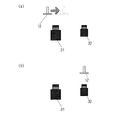
図1のステップ#11で、図2(a)に示すように、正方形平面の各辺に円形の検出対象を等間隔に配した測定治具12を校正対象である撮像装置11の視野中央で撮像される位置に回転しない状態で設置する。次に、ステップ#12で設置された測定治具12を撮像し、画像データ13を得る。次に、ステップ#13で、図2(b)に示すように得られた画像データを格子状にスキャンし、明るさ変化の大きい位置14つまり正方形平面の各辺に配された円形検出対象を検出する。明るさの変化の大きい位置14を検出したら、隣合う変化の大きい位置へと順次追跡を行い、円形検出対象の境界点15を検出する。同様にして全ての円形検出対象の境界点15を検出する。全ての円形の検出対象の境界点15が求まったら、各円形検出対象の境界点15の重心を求め、それを円形検出対象の中心位置と決定する。次に、ステップ#14で、校正値を計算する。
【0023】
校正値の計算は次のようにして行われる。図2(c)に示すように検出された円形検出対象の中心位置P1〜P32の平均から測定治具12の中心16を算出する。はじめに測定治具12を視野の中心に位置するように設置していたので、算出した中心16と視野中心とのずれ量dx,dyが撮像装置11の取付位置ずれ量となる。
【0024】
次に、図2(d)に示すように各辺の円形検出対象の中心位置を直線近似17とし、それらの直線の傾きからθ1〜θ4を求める。得られたθ1〜θ4の平均から測定治具12の傾きθを求める。始めに測定治具12を回転しない状態で設置しているので、測定治具12の傾きθが撮像装置の取付回転ずれ量となる。
【0025】
次に、図2(e)に示すように対面する円形検出対象間の距離l1〜l18の平均から測定治具の画像パターン18のサイズlを求める。測定治具のサイズLと画像パターン18のサイズlの比から1画素の実寸換算値を算出する。
【0026】
次に、本発明の第2の実施形態の計測用撮像装置の校正値測定方法について、図3、図4を参照して説明する。
【0027】
図4(a)に示すように対象物又は撮像装置を移動しながら1行づつ撮像する1次元の撮像素子を有する撮像装置21をθだけ回転させて取付けている場合、正方形の対象物24を矢印の方向に移動させて撮像すると、まず正方形対象物24の頂点Bが撮像され続いて頂点Aが撮像されていく。従って入力された画像パターン25は正方形ABCDでなく平行四辺形A’B’C’D’となる。撮像された平行四辺形A’B’C’D’において頂点A’の位置は正方形の頂点Aに対し、
A'x=Ax+L×( cosθ−cos2θ)
A'y=Ay+L× sinθ
という関係で表される。ここで、撮像装置21の取付回転ずれ量がそれほど大きくないことを考えれば、X方向への変位は無視できる値であるから、回転ずれしている1次元の撮像素子を有する撮像装置21で撮影した場合、撮像された画像は撮像素子と垂直方向へ回転ずれ量分だけ変位することになる。本実施形態ではこの特性を利用し、測定治具の回転量と撮像装置の取付回転ずれ量を同時に測定する。
【0028】
まず、図3のステップ#21で、図4(b)に示すように、正方形平面の各辺に円形検出対象を等間隔に配した測定治具12を校正対象となる1次元の撮像素子を有する撮像装置21の視野中央で撮像されるように設置する。このとき測定治具12は回転していてもかまわない。次に、ステップ#22で1次元の撮像素子を有する撮像装置21を矢印の方向へ移動しながら測定治具12を撮像し、画像データ23を得る。次に、ステップ#23で上記第1の実施形態で説明したのと同じ要領で測定治具の画像データより正方形平面の各辺に配された円形検出対象の各中心位置を検出する。
【0029】
次に、ステップ#24で測定治具12の傾きを計算し、続いてステップ#25で回転ずれ量を算出する。図4(c)に示すように、各辺の円形検出対象の中心位置を直線近似27し、それらの直線の傾きθ1〜θ4を求める。そして左右の辺の傾きをθ3、θ4の平均値で求め、上下の辺の傾きをθ1、θ2の平均値で求める。上述のように、左右辺では回転ずれした1次元の撮像素子を有する撮像装置21の影響を受けないので、求められた左右辺の傾きは測定治具12の回転量となる。上下辺では回転ずれした1次元の撮像素子を有する撮像装置21の影響を受けるので、求められた上下辺の傾きは測定治具12の回転量と撮像装置21の回転ずれ量が含まれている。よって、上下辺の傾きから左右辺の傾きを差し引いた傾きが撮像装置21の取付回転ずれ量となる。
【0030】
次に、本発明の第3の実施形態の計測用撮像装置の校正値測定方法について、図5、図6を参照して説明する。
【0031】
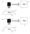
図6(a)に示すように大・小2種の視野サイズの撮像装置を搭載した電子部品実装設備における撮像装置の校正値測定について説明する。大視野撮像装置31は1次元の撮像素子を有する撮像装置で、小視野撮像装置32は2次元の撮像素子を有する撮像装置である。まず、上記第1、第2の実施形態と同様の測定治具12を大視野撮像装置31の視野中央へ撮像されるように矢印の方向へ移動しながら撮像する。そうしてまず、ステップ#31で第2の実施形態で説明した要領で測定治具12の回転量を測定し、合わせてステップ#32、#33で第1及び第2の実施形態で説明した要領にて大視野撮像装置31の取付位置ずれ量、取付回転ずれ量、1画素の実寸換算値を測定する。
【0032】
次に、図6(b)に示すように測定治具12を小視野撮像装置32の視野中央で撮像されるように測定治具12が回転しないように平行移動して配置し、小視野撮像装置32で撮像する。そしてステップ#32、#33で第1の実施形態で説明した要領にて小視野撮像装置32の取付位置ずれ量、取付回転ずれ量、1画素の実寸換算値を測定する。測定された取付回転ずれ量には測定治具12の回転量も含まれているので、測定された取付回転ずれ量から先に求めた測定治具12の回転量を差し引いて真の小視野撮像装置32の取付回転ずれ量を求める。
【0033】
【発明の効果】
本発明の計測用撮像装置の校正値測定方法によれば、以上の説明から明らかなように、測定治具の周囲に配した検出対象の中心位置から各校正値を測定するため、照明や測定治具のエッジ形状の影響を受け難い上、複数の検出対象を測定して平均化することでより高精度な校正値を測定することができる。
【0034】
また、測定治具の回転量を撮像装置の取付回転ずれ量とは別に測定することができるため、電子部品実装設備において測定治具の回転量を0にするような調整が必要でなく、自動的に全ての撮像装置の校正値を正確に測定することができる等の効果を発揮する。
【図面の簡単な説明】
【図1】本発明の計測用撮像装置の校正値測定方法の第1の実施形態のフローチャートである。
【図2】同実施形態の校正値測定方法の説明図である。
【図3】本発明の計測用撮像装置の校正値測定方法の第2の実施形態のフローチャートである。
【図4】同実施形態の校正値測定方法の説明図である。
【図5】本発明の計測用撮像装置の校正値測定方法の第2の実施形態のフローチャートである。
【図6】同実施形態の校正値測定方法の説明図である。
【図7】校正値である取付位置ずれ量の説明図である。
【図8】校正値である取付回転ずれ量の説明図である。
【図9】校正値である1画素の実寸換算値の説明図である。
【図10】従来例の計測用撮像装置の校正値測定方法の説明図である。
【図11】他の従来例の計測用撮像装置の校正値測定方法の説明図である。
【図12】従来例の校正値測定方法における測定誤差発生の説明図である。
【符号の説明】
11、21、31、32 撮像装置
12 測定治具
13、23 撮像した画像データ[0001]
BACKGROUND OF THE INVENTION
The present invention relates to a calibration value measurement method for calibrating a measurement imaging apparatus in an electronic component mounting facility or the like.
[0002]
[Prior art]
In recent years, in the electronic component mounting field, a technology for mounting electronic components on a circuit board at high speed and with high accuracy is required. Generally, image data obtained by imaging electronic components and board marks is processed at high speed to accurately detect the position and rotation amount of electronic components and the center position of board marks, and the mounting position and rotation of electronic components. Image recognition technology that corrects the amount is incorporated.
[0003]
In the image recognition, the correction amount is determined by processing the image data captured by the measurement imaging device, and the correction amount depends on the mounting accuracy of the imaging device. Therefore, the mounting error of the measurement imaging device is measured in advance, the mounting error is calibrated, and the correction value is calculated, thereby realizing high-accuracy mounting.
[0004]
There are mainly three factors that cause the measurement accuracy of the mounting position / rotation correction amount to decrease due to the mounting error of the imaging apparatus.
[0005]
The first factor is the mounting position shift of the imaging device. As shown in FIG. 7A, in the image recognition, the position correction target (dx, dy) is measured by measuring at which position of the image data 44 obtained by imaging the imaging
[0006]
The second factor is the mounting rotation deviation of the imaging device. As shown in FIG. 8A, in the image recognition, the rotation correction amount θ is obtained by measuring how much the
[0007]
The third factor is a shift in the actual size conversion value of one pixel due to a shift in the distance between the imaging apparatus and the target. Although there is an optical shift due to a shift in the lens shape as a shift in the distance, for the sake of simplicity, the shift in the positional relationship between the imaging apparatus and the target will be described. As shown in FIG. 9A, the
[0008]
In order to calibrate these error factors, it is necessary to accurately measure errors caused by these error factors in advance. As a conventionally used method, there is a method of measuring a square jig. As shown in FIG. 10A, a
[0009]
Another method is to move the jig within the field of view. As shown in FIG. 11A, first, the
[0010]
[Problems to be solved by the invention]
However, when a square jig is used, there is a problem that an error occurs due to the lighting of the jig or the way the jig shines due to the edge shape of the jig. As shown in FIG. 12A, in the process of detecting each side of the
[0011]
At this time, if the threshold value for detecting the edge point is set to a value of 75, the edge line of the
[0012]
If the edge lines on the two sides are wrong, errors dx and dy occur at the center position as shown in FIG. If only the edge information of one corner is wrong, an error θ occurs in the slope as shown in FIG. Furthermore, if all sides are mistaken evenly, the jig pattern size l becomes l ′ as shown in FIG. 12D, and an error occurs in the actual size conversion value of one pixel.
[0013]
In the method of moving the jig within the field of view, unlike the square jig, there is not much error in the edge position. Because the object is smaller than in the case of the square jig, the error of the edge similarly occurs in the whole. Since they are generated in the same manner, the average of the centers is the same position as when there is no edge error. In this method, the calibration value is calculated using the center position of the measuring jig at different positions measured by the same method, so that it can be said that the influence of the edge error is small. However, this method causes an error due to the means for movement. Therefore, if the movement is not performed accurately, a positional deviation, a rotational deviation, and a one-pixel actual size converted value deviation occur as in a square jig.
[0014]
There is another problem when using a square jig. It is a measurement of the amount of rotational deviation of the imaging device. In the measurement of the rotation deviation amount, the rotation amount of the imaged measurement jig pattern is measured and obtained as the rotation deviation amount of the imaging device. In this case, the precondition that the rotation amount of the measurement jig is zero is necessary. . However, in practice, it is very difficult to reduce the rotation amount of the measuring jig to zero, and this is a great obstacle when all of the mounting equipment is automatically measured.
[0015]
An object of the present invention is to provide a calibration value measuring method capable of automatically and accurately measuring a calibration value in a measurement imaging apparatus in view of the above-described conventional problems.
[0016]
[Means for Solving the Problems]
According to a first aspect of the present invention, there is provided a calibration value measuring method for a measurement imaging apparatus in which a measurement jig in which detection targets are arranged at predetermined intervals around a predetermined position is placed in a predetermined positional relationship with an imaging apparatus as a calibration target. A step, a second step of capturing an image of the installed measurement jig and obtaining image data, a third step of detecting each central position of the surrounding detection target from the image data of the measurement jig, and each central position of the detection target And a fourth step of calculating a calibration value of the imaging device from the measurement device, wherein the measurement jig arranges circular detection targets at equal intervals on each side of the square plane. The calibration value calculates the mounting position deviation amount of the imaging apparatus from the average value of the center positions of the detection targets, and the mounting rotation deviation amount of the imaging apparatus from the slope of the straight line approximated to the center position of the detection targets on each side. Is calculated .
More preferably, the actual size conversion value of one pixel of the imaging device is calculated from the interval of the detection target.
[0017]
Since each calibration value is measured from the center position of the detection target placed around the measurement jig in this way, it is not easily affected by the lighting or the edge shape of the measurement jig, and multiple detection targets are measured and averaged. By doing so, a more accurate calibration value can be measured.
[0019]
According to a second aspect of the present invention, there is provided a calibration value measurement method for a measurement imaging apparatus, wherein the first step is a one-dimensional imaging in which an installed measurement jig is imaged line by line while moving the measurement jig or the imaging apparatus. A second step of obtaining an image data by imaging using an imaging device having an element; the third step; a slope of a straight line approximated to a center position of a detection target arranged on a side along the moving direction; and a moving direction The fourth step of calculating the inclination of the straight line approximated to the center position of the detection object arranged on the side opposite to the side, and the amount of rotation of the measuring jig is calculated from the inclination of the side along the moving direction. A fifth step of calculating an attachment rotation deviation amount of the imaging apparatus from an inclination obtained by subtracting an inclination of the side along the moving direction from an inclination of the opposite side, and thereby an imaging apparatus having a one-dimensional image sensor Similarly, the calibration value can be measured. Further, the inclination of the side along the moving direction represents the rotation amount of the measuring jig, and the inclination of the side facing the moving direction represents the sum of the rotational deviation amounts of the measuring jig and the imaging device. The amount of rotation and the amount of attachment rotation deviation of the imaging device can be measured separately at the same time, and adjustment to make the amount of rotation of the measuring jig zero is not necessary.
[0020]
According to a third aspect of the present invention, there is provided a calibration value measuring method for an imaging apparatus for measurement, which includes a plurality of imaging apparatuses each including one or more imaging apparatuses having a one-dimensional imaging element and one imaging apparatus having a two-dimensional imaging element. In a component mounting facility, a first step of acquiring the rotation amount of the measuring jig using the calibration method of the second invention, a second step of calculating a calibration value of the imaging device by the calibration method of the first invention, and imaging When the apparatus has an imaging device having a two-dimensional image sensor, the true image pickup apparatus is attached by subtracting the rotation amount of the measuring jig obtained in the first step from the attachment rotation deviation amount obtained in the second step. And a third step for recalculating the amount of rotational deviation, and it is not necessary to adjust the rotational amount of the measuring jig to zero as described above, and the calibration values of all imaging devices are automatically set. Can be measured accurately.
[0021]
DETAILED DESCRIPTION OF THE INVENTION
Hereinafter, a calibration value measurement method for the measurement imaging apparatus according to the first embodiment of the present invention will be described with reference to FIGS. 1 and 2.
[0022]
In
[0023]
The calibration value is calculated as follows. The
[0024]
Next, as shown in FIG. 2 (d), the center position of the circular detection target of each side is set to the
[0025]
Next, as shown in FIG. 2E, the size l of the
[0026]
Next, a calibration value measurement method for the measurement imaging apparatus according to the second embodiment of the present invention will be described with reference to FIGS.
[0027]
As shown in FIG. 4A, when the
A′x = Ax + L × (cos θ−cos 2 θ)
A'y = Ay + L × sinθ
It is expressed by the relationship. Here, considering that the amount of mounting rotation deviation of the
[0028]
First, in
[0029]
Next, the inclination of the measuring
[0030]
Next, a calibration value measurement method for the measurement imaging apparatus according to the third embodiment of the present invention will be described with reference to FIGS.
[0031]
The calibration value measurement of the image pickup apparatus in the electronic component mounting facility in which the image pickup apparatus having two types of large and small visual field sizes as shown in FIG. The large-
[0032]
Next, as shown in FIG. 6B, the
[0033]
【The invention's effect】
According to the calibration value measurement method of the measurement imaging apparatus of the present invention, as is apparent from the above description, each calibration value is measured from the center position of the detection target arranged around the measurement jig. It is difficult to be influenced by the edge shape of the jig, and more accurate calibration values can be measured by measuring and averaging a plurality of detection targets.
[0034]
In addition, since the rotation amount of the measurement jig can be measured separately from the amount of mounting rotation deviation of the imaging device, there is no need to adjust the rotation amount of the measurement jig to zero in the electronic component mounting facility, and automatic In particular, it is possible to accurately measure the calibration values of all the imaging devices.
[Brief description of the drawings]
FIG. 1 is a flowchart of a first embodiment of a calibration value measuring method for an imaging apparatus for measurement according to the present invention.
FIG. 2 is an explanatory diagram of a calibration value measurement method according to the embodiment.
FIG. 3 is a flowchart of a second embodiment of the calibration value measuring method of the measurement imaging apparatus of the present invention.
FIG. 4 is an explanatory diagram of a calibration value measuring method according to the embodiment;
FIG. 5 is a flowchart of a second embodiment of the calibration value measuring method of the measurement imaging apparatus of the present invention.
FIG. 6 is an explanatory diagram of a calibration value measuring method according to the embodiment;
FIG. 7 is an explanatory diagram of a mounting position deviation amount that is a calibration value.
FIG. 8 is an explanatory diagram of a mounting rotation deviation amount that is a calibration value.
FIG. 9 is an explanatory diagram of an actual size converted value of one pixel which is a calibration value.
FIG. 10 is an explanatory diagram of a calibration value measurement method of a conventional measurement imaging apparatus.
FIG. 11 is an explanatory diagram of a calibration value measuring method of another conventional imaging apparatus for measurement.
FIG. 12 is an explanatory diagram of measurement error generation in the calibration value measurement method of the conventional example.
[Explanation of symbols]
11, 21, 31, 32
Claims (4)
Priority Applications (1)
| Application Number | Priority Date | Filing Date | Title |
|---|---|---|---|
| JP15893897A JP3893191B2 (en) | 1997-06-16 | 1997-06-16 | Calibration value measurement method for measurement imaging device |
Applications Claiming Priority (1)
| Application Number | Priority Date | Filing Date | Title |
|---|---|---|---|
| JP15893897A JP3893191B2 (en) | 1997-06-16 | 1997-06-16 | Calibration value measurement method for measurement imaging device |
Publications (2)
| Publication Number | Publication Date |
|---|---|
| JPH116711A JPH116711A (en) | 1999-01-12 |
| JP3893191B2 true JP3893191B2 (en) | 2007-03-14 |
Family
ID=15682633
Family Applications (1)
| Application Number | Title | Priority Date | Filing Date |
|---|---|---|---|
| JP15893897A Expired - Fee Related JP3893191B2 (en) | 1997-06-16 | 1997-06-16 | Calibration value measurement method for measurement imaging device |
Country Status (1)
| Country | Link |
|---|---|
| JP (1) | JP3893191B2 (en) |
Families Citing this family (7)
| Publication number | Priority date | Publication date | Assignee | Title |
|---|---|---|---|---|
| JPS61156213A (en) * | 1984-12-28 | 1986-07-15 | Canon Inc | Zoom lens |
| JP5318334B2 (en) * | 2006-05-19 | 2013-10-16 | Juki株式会社 | Method and apparatus for detecting position of object |
| JP5318728B2 (en) * | 2009-11-04 | 2013-10-16 | 大和小田急建設株式会社 | Deformation detection method of concrete surface layer by infrared method |
| JP6025386B2 (en) * | 2012-05-02 | 2016-11-16 | キヤノン株式会社 | Image measuring apparatus, image measuring method, and image measuring program |
| JP6955697B2 (en) * | 2017-03-02 | 2021-10-27 | 株式会社リコー | Conveyor device, image forming device and post-processing device |
| CN108613630B (en) * | 2018-04-28 | 2022-03-11 | 中国计量大学 | Two-wire tube level bubble offset measurement method based on image processing technology |
| WO2020129850A1 (en) * | 2018-12-21 | 2020-06-25 | オムロン株式会社 | Method for correcting values detected by linear scales |
-
1997
- 1997-06-16 JP JP15893897A patent/JP3893191B2/en not_active Expired - Fee Related
Also Published As
| Publication number | Publication date |
|---|---|
| JPH116711A (en) | 1999-01-12 |
Similar Documents
| Publication | Publication Date | Title |
|---|---|---|
| US6535291B1 (en) | Calibration methods for placement machines incorporating on-head linescan sensing | |
| US6067165A (en) | Position calibrating method for optical measuring apparatus | |
| US7177740B1 (en) | Method and apparatus for dynamic measuring three-dimensional parameters of tire with laser vision | |
| US4738025A (en) | Automated apparatus and method for positioning multicontact component | |
| JP4901903B2 (en) | 3D inspection system | |
| US5671056A (en) | Three-dimensional form measuring apparatus and method | |
| US20070121122A1 (en) | Method for the automatic parameterization of measuring systems | |
| US20210291376A1 (en) | System and method for three-dimensional calibration of a vision system | |
| US6861282B2 (en) | Semiconductor package and semiconductor package mounting method | |
| CN112539714B (en) | Eccentricity detection method, processing method and detection equipment | |
| JP2010281621A (en) | Three-dimensional shape measuring instrument | |
| JP3893191B2 (en) | Calibration value measurement method for measurement imaging device | |
| KR101633139B1 (en) | A method and means for measuring positions of contact elements of an electronic components | |
| US5978094A (en) | Alignment device and method based on imaging characteristics of the image pickup system | |
| JP4284765B2 (en) | Robot hand position measuring device | |
| JPH01236700A (en) | Inspection and orientation recognition method of component lead | |
| JP2001124700A (en) | Calibration method of inspection machine with line sensor camera | |
| JP3823488B2 (en) | IC lead float inspection device and inspection method | |
| KR20090004642A (en) | Method for placing at least one component provided with connection points on a substrate, as well as such a device | |
| JP3369235B2 (en) | Calibration method for measuring distortion in three-dimensional measurement | |
| JPS6311804A (en) | Mark position detection system for positioning | |
| JPH0652167B2 (en) | Image processing method | |
| JP3923168B2 (en) | Component recognition method and component mounting method | |
| JPH04338700A (en) | Board mark recognition device | |
| JP3779118B2 (en) | Method for detecting displacement of camera in imaging apparatus, method for detecting tilt of camera in imaging apparatus, and method for correcting movement amount of camera in imaging apparatus |
Legal Events
| Date | Code | Title | Description |
|---|---|---|---|
| A621 | Written request for application examination |
Free format text: JAPANESE INTERMEDIATE CODE: A621 Effective date: 20040528 |
|
| A977 | Report on retrieval |
Free format text: JAPANESE INTERMEDIATE CODE: A971007 Effective date: 20051221 |
|
| A131 | Notification of reasons for refusal |
Free format text: JAPANESE INTERMEDIATE CODE: A131 Effective date: 20060516 |
|
| A521 | Written amendment |
Free format text: JAPANESE INTERMEDIATE CODE: A523 Effective date: 20060705 |
|
| TRDD | Decision of grant or rejection written | ||
| A01 | Written decision to grant a patent or to grant a registration (utility model) |
Free format text: JAPANESE INTERMEDIATE CODE: A01 Effective date: 20061114 |
|
| A61 | First payment of annual fees (during grant procedure) |
Free format text: JAPANESE INTERMEDIATE CODE: A61 Effective date: 20061211 |
|
| R150 | Certificate of patent or registration of utility model |
Free format text: JAPANESE INTERMEDIATE CODE: R150 |
|
| FPAY | Renewal fee payment (event date is renewal date of database) |
Free format text: PAYMENT UNTIL: 20091215 Year of fee payment: 3 |
|
| FPAY | Renewal fee payment (event date is renewal date of database) |
Free format text: PAYMENT UNTIL: 20101215 Year of fee payment: 4 |
|
| FPAY | Renewal fee payment (event date is renewal date of database) |
Free format text: PAYMENT UNTIL: 20101215 Year of fee payment: 4 |
|
| FPAY | Renewal fee payment (event date is renewal date of database) |
Free format text: PAYMENT UNTIL: 20111215 Year of fee payment: 5 |
|
| FPAY | Renewal fee payment (event date is renewal date of database) |
Free format text: PAYMENT UNTIL: 20111215 Year of fee payment: 5 |
|
| FPAY | Renewal fee payment (event date is renewal date of database) |
Free format text: PAYMENT UNTIL: 20121215 Year of fee payment: 6 |
|
| FPAY | Renewal fee payment (event date is renewal date of database) |
Free format text: PAYMENT UNTIL: 20121215 Year of fee payment: 6 |
|
| FPAY | Renewal fee payment (event date is renewal date of database) |
Free format text: PAYMENT UNTIL: 20131215 Year of fee payment: 7 |
|
| S533 | Written request for registration of change of name |
Free format text: JAPANESE INTERMEDIATE CODE: R313533 |
|
| R350 | Written notification of registration of transfer |
Free format text: JAPANESE INTERMEDIATE CODE: R350 |
|
| S111 | Request for change of ownership or part of ownership |
Free format text: JAPANESE INTERMEDIATE CODE: R313113 |
|
| R350 | Written notification of registration of transfer |
Free format text: JAPANESE INTERMEDIATE CODE: R350 |
|
| LAPS | Cancellation because of no payment of annual fees |