JP3891069B2 - Fuel cell separator - Google Patents
Fuel cell separator Download PDFInfo
- Publication number
- JP3891069B2 JP3891069B2 JP2002233621A JP2002233621A JP3891069B2 JP 3891069 B2 JP3891069 B2 JP 3891069B2 JP 2002233621 A JP2002233621 A JP 2002233621A JP 2002233621 A JP2002233621 A JP 2002233621A JP 3891069 B2 JP3891069 B2 JP 3891069B2
- Authority
- JP
- Japan
- Prior art keywords
- cell
- flow path
- gas flow
- metal plate
- terminal
- Prior art date
- Legal status (The legal status is an assumption and is not a legal conclusion. Google has not performed a legal analysis and makes no representation as to the accuracy of the status listed.)
- Expired - Fee Related
Links
Images
Classifications
-
- H—ELECTRICITY
- H01—ELECTRIC ELEMENTS
- H01M—PROCESSES OR MEANS, e.g. BATTERIES, FOR THE DIRECT CONVERSION OF CHEMICAL ENERGY INTO ELECTRICAL ENERGY
- H01M8/00—Fuel cells; Manufacture thereof
- H01M8/02—Details
- H01M8/0202—Collectors; Separators, e.g. bipolar separators; Interconnectors
- H01M8/0204—Non-porous and characterised by the material
- H01M8/0206—Metals or alloys
- H01M8/0208—Alloys
- H01M8/021—Alloys based on iron
-
- H—ELECTRICITY
- H01—ELECTRIC ELEMENTS
- H01M—PROCESSES OR MEANS, e.g. BATTERIES, FOR THE DIRECT CONVERSION OF CHEMICAL ENERGY INTO ELECTRICAL ENERGY
- H01M8/00—Fuel cells; Manufacture thereof
- H01M8/02—Details
- H01M8/0202—Collectors; Separators, e.g. bipolar separators; Interconnectors
- H01M8/0204—Non-porous and characterised by the material
- H01M8/0213—Gas-impermeable carbon-containing materials
-
- H—ELECTRICITY
- H01—ELECTRIC ELEMENTS
- H01M—PROCESSES OR MEANS, e.g. BATTERIES, FOR THE DIRECT CONVERSION OF CHEMICAL ENERGY INTO ELECTRICAL ENERGY
- H01M8/00—Fuel cells; Manufacture thereof
- H01M8/02—Details
- H01M8/0202—Collectors; Separators, e.g. bipolar separators; Interconnectors
- H01M8/0204—Non-porous and characterised by the material
- H01M8/0223—Composites
- H01M8/0228—Composites in the form of layered or coated products
-
- H—ELECTRICITY
- H01—ELECTRIC ELEMENTS
- H01M—PROCESSES OR MEANS, e.g. BATTERIES, FOR THE DIRECT CONVERSION OF CHEMICAL ENERGY INTO ELECTRICAL ENERGY
- H01M8/00—Fuel cells; Manufacture thereof
- H01M8/02—Details
- H01M8/0202—Collectors; Separators, e.g. bipolar separators; Interconnectors
- H01M8/0258—Collectors; Separators, e.g. bipolar separators; Interconnectors characterised by the configuration of channels, e.g. by the flow field of the reactant or coolant
-
- H—ELECTRICITY
- H01—ELECTRIC ELEMENTS
- H01M—PROCESSES OR MEANS, e.g. BATTERIES, FOR THE DIRECT CONVERSION OF CHEMICAL ENERGY INTO ELECTRICAL ENERGY
- H01M8/00—Fuel cells; Manufacture thereof
- H01M8/02—Details
- H01M8/0271—Sealing or supporting means around electrodes, matrices or membranes
- H01M8/0273—Sealing or supporting means around electrodes, matrices or membranes with sealing or supporting means in the form of a frame
-
- H—ELECTRICITY
- H01—ELECTRIC ELEMENTS
- H01M—PROCESSES OR MEANS, e.g. BATTERIES, FOR THE DIRECT CONVERSION OF CHEMICAL ENERGY INTO ELECTRICAL ENERGY
- H01M8/00—Fuel cells; Manufacture thereof
- H01M8/24—Grouping of fuel cells, e.g. stacking of fuel cells
- H01M8/2465—Details of groupings of fuel cells
- H01M8/2483—Details of groupings of fuel cells characterised by internal manifolds
-
- Y—GENERAL TAGGING OF NEW TECHNOLOGICAL DEVELOPMENTS; GENERAL TAGGING OF CROSS-SECTIONAL TECHNOLOGIES SPANNING OVER SEVERAL SECTIONS OF THE IPC; TECHNICAL SUBJECTS COVERED BY FORMER USPC CROSS-REFERENCE ART COLLECTIONS [XRACs] AND DIGESTS
- Y02—TECHNOLOGIES OR APPLICATIONS FOR MITIGATION OR ADAPTATION AGAINST CLIMATE CHANGE
- Y02E—REDUCTION OF GREENHOUSE GAS [GHG] EMISSIONS, RELATED TO ENERGY GENERATION, TRANSMISSION OR DISTRIBUTION
- Y02E60/00—Enabling technologies; Technologies with a potential or indirect contribution to GHG emissions mitigation
- Y02E60/30—Hydrogen technology
- Y02E60/50—Fuel cells
Landscapes
- Chemical & Material Sciences (AREA)
- Life Sciences & Earth Sciences (AREA)
- Engineering & Computer Science (AREA)
- Manufacturing & Machinery (AREA)
- Sustainable Development (AREA)
- Sustainable Energy (AREA)
- Chemical Kinetics & Catalysis (AREA)
- Electrochemistry (AREA)
- General Chemical & Material Sciences (AREA)
- Composite Materials (AREA)
- Fuel Cell (AREA)
Description
【0001】
【発明の属する技術分野】
本発明は低温型燃料電池、とくに固体高分子電解質型燃料電池、のセパレータに関し、セパレータの金属板の表面処理構造に関する。
【0002】
【従来の技術】
固体高分子電解質型燃料電池は、膜−電極アッセンブリ(MEA:Membrane-Electrode Assembly )とセパレータとの積層体からなる。膜−電極アッセンブリは、イオン交換膜からなる電解質膜とこの電解質膜の一面に配置された触媒層からなる電極(アノード、燃料極)および電解質膜の他面に配置された触媒層からなる電極(カソード、空気極)とからなる。膜−電極アッセンブリとセパレータとの間には、アノード側、カソード側にそれぞれ拡散層が設けられる。セパレータには、アノードに燃料ガス(水素)を供給するための燃料ガス流路が形成され、カソードに酸化ガス(酸素、通常は空気)を供給するための酸化ガス流路が形成されている。また、セパレータには冷媒(通常、冷却水)を流すための冷媒流路も形成されている。膜−電極アッセンブリとセパレータを重ねてセルを構成し、少なくとも1つのセルからモジュールを構成し、モジュールを積層してセル積層体とし、セル積層体のセル積層方向両端に、ターミナル、インシュレータ、エンドプレートを配置し、セル積層体をセル積層方向に締め付け、セル積層体の外側でセル積層方向に延びる締結部材(たとえば、テンションプレート)、ボルト・ナットにて固定して、スタックを構成する。
各セルの、アノード側では、水素を水素イオン(プロトン)と電子にする反応が行われ、水素イオンは電解質膜中をカソード側に移動し、カソード側では酸素と水素イオンおよび電子(隣りのMEAのアノードで生成した電子がセパレータを通してくる、またはセル積層方向一端のセルのアノードで生成した電子が外部回路を通して他端のセルのカソードにくる)から水を生成するつぎの反応が行われる。
アノード側:H2 →2H+ +2e-
カソード側:2H+ +2e- +(1/2)O2 →H2 O
各セル毎に、または複数のセル毎に、セルで正常な発電が行われていることを確認するとともに、セル電圧に基づいて反応ガスの流量制御を行ったり、異常電圧の場合にモータにガイドをかけるために、セル電圧がモニタされる。
特開平11−339828号は、燃料電池のセル電圧モニタを開示している。また、特開2001−283880は、メタルセパレータのガス流路部の耐食性向上のために、メタルセパレータ全体にカーボンコートを施すことを開示している。
【0003】
【発明が解決しようとする課題】
しかし、従来技術には、つぎの問題がある。
メタルセパレータの、セル電圧モニタ端子接触部にカーボンコートが施されていると、メタルセパレータの、端子接触部の接触抵抗が安定しなくなり、セル電圧検出精度が低下する。また、カーボンコートを施さないと、ガス流路部の腐食の進行が早くなる。したがって、端子接触部の接触抵抗の安定と、ガス流路部の耐食性とを両立させることが困難である。
本発明の目的は、ガス流路部の耐食性を低下させることなく、端子接触部の接触抵抗を安定させることができる、燃料電池のセパレータを提供することにある。
【0004】
【課題を解決するための手段】
上記目的を達成する本発明はつぎの通りである。
(1) 金属板を有し、該金属板はガス流路部とガス流路部外にセル電圧モニター端子との接触部を有する燃料電池のセパレータであって、
前記ガス流路部では、前記金属板に金属メッキが施されるとともに該金属メッキの上にカーボンコートが施されており、
前記ガス流路部外の前記セル電圧モニター端子との接触部では、カーボンコート時に前記セル電圧モニター端子との接触部をマスキングすることにより、前記金属板に前記金属メッキが施されたままとされている燃料電池のセパレータ。
(2) 前記金属板はステンレス板であり、前記金属メッキは金メッキである(1)記載の燃料電池のセパレータ。
(3) 前記ガス流路部は周囲をシール材でシールされており、該シール材の内縁より外が前記ガス流路部外である(1)記載の燃料電池のセパレータ。
【0005】
上記(1)〜(3)の燃料電池のセパレータでは、ガス流路部では、金属メッキが施されるとともに該金属メッキの上にカーボンコートが施されており、ガス流路部外のセル電圧モニター端子との接触部では、カーボンコート時に前記セル電圧モニター端子との接触部をマスキングすることにより、金属板に金属メッキが施されたままとされているので、ガス流路部には耐食性のある表面処理を施し、セル電圧モニター端子接触部には接触抵抗を少なくし、かつ、安定化させる表面処理を施すことにより、ガス流路部の耐食性を良好に維持しながら、端子接触部の接触抵抗を安定させることができる。その結果、端子接触部の接触抵抗の安定と、ガス流路部の耐食性とを容易に両立させることができる。
ガス流路部の表面処理はカーボンコートを含み、セル電圧モニター端子との接触部の表面処理は金属メッキのままでカーボンコートを含まないようにしたので、ガス流路部の耐食性を良好に維持しながら、端子接触部の接触抵抗を安定させることができる。その結果、端子接触部の接触抵抗の安定と、ガス流路部の耐食性とを容易に両立させることができる。
【0006】
【発明の実施の形態】
以下に、本発明の燃料電池のセパレータを図1〜図8を参照して説明する。
本発明で対象となる燃料電池は低温型燃料電池であり、たとえば固体高分子電解質型燃料電池10である。該燃料電池10は、たとえば燃料電池自動車に搭載される。ただし、自動車以外に用いられてもよい。
【0007】
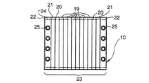
固体高分子電解質型燃料電池10は、図1、図2に示すように、膜−電極アッセンブリ(MEA:Membrane-Electrode Assembly )とセパレータ18との積層体からなる。膜−電極アッセンブリは、イオン交換膜からなる電解質膜11と、この電解質膜の一面に配置された触媒層12からなる電極(アノード、燃料極)14および電解質膜11の他面に配置された触媒層15からなる電極(カソード、空気極)17とからなる。膜−電極アッセンブリとセパレータ18との間には、アノード側、カソード側にそれぞれ拡散層13、16が設けられる。
膜−電極アッセンブリとセパレータ18を重ねてセル19を構成し、少なくとも1つのセルからモジュールを構成し、モジュールを積層してセル積層体とし、セル積層体のセル積層方向両端に、ターミナル20、インシュレータ21、エンドプレート22を配置し、セル積層体をセル積層方向に締め付け、セル積層体の外側でセル積層方向に延びる締結部材(たとえば、テンションプレート24)、ボルト・ナット25にて固定して、スタック23を構成する。
【0008】
セパレータ18には、アノード14に燃料ガス(水素)を供給するための燃料ガス流路27が形成され、カソード17に酸化ガス(酸素、通常は空気)を供給するための酸化ガス流路28が形成されている。また、セパレータには冷媒(通常、冷却水)を流すための冷媒流路26も形成されている。冷媒流路26はセル毎に、または複数のセル毎に(たとえば、モジュール毎に)設けられている。
セパレータ18は、金属板29と樹脂フレーム30とを有する合成セパレータである。
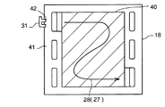
図3に示すように、金属板29はセル面内中央部にガス流路部40とガス流路部外の部分41とを有し、ガス流路部40にガス流路27、28が形成される。ガス流路部40では金属板29は一面で燃料ガスと酸化ガスの何れか一方に触れ、他面で冷却水または燃料ガスと酸化ガスの他方に触れる。ガス流路部40は周囲で接着剤、シール材でシールされ、シール部内縁より外がガス流路部外の部分41で、ガス流路部外の部分41ではガスマニホールド部を除き金属板29は燃料ガス、酸化ガスに接触しない。樹脂フレーム40はセル面内のセル外周部に設けられる。
【0009】
プラス側の金属板29とマイナス側の金属板29との間にMEAが挟まれ、セル面内中央部では金属板29のMEA側にガス流路27、28が形成され、周囲部ではプラス側の金属板29とマイナス側の金属板29との間に電解質膜11が挟まれる。金属板29同士の間、樹脂フレーム30と金属板29との間、金属板29と電解質膜11との間は、シール材を兼ねる接着剤にてシールされる。
電解質膜11を挟んで対峙するプラス側の金属板とマイナス側の金属板との間には電位差があり、その電位差は約1ボルトである。1つのセル19のプラス側の金属板29と、隣りのセル19のマイナス側の金属板29とはセル面内中央部で接触していて、電位差はない。
【0010】
複数のセル電圧モニター31が燃料電池スタック23に取付けられている。
各セル電圧モニター31は、燃料電池スタックへの固定部35を有する1つのハウジング33と、そのハウジング33で保持された1つ以上の端子32を含む。端子32は導電性で金属製(金属メッキのものを含む)であり、ハウジング33は非導電性でたとえば樹脂製である。
各セル電圧モニター31の1つ以上の端子32は、そのセル電圧モニター31のハウジング33内で、端子32同士互いに並列に、かつ、燃料電池スタック23のセル積層方向に列状に、配置されている。
また、各セル電圧モニター31に1つづつ設けられた複数のハウジング33は燃料電池スタック23の側面(四側の側面の一つの側面)に配置されている。
セル電圧モニター31の極数は、そのセル電圧モニター31のハウジング33に保持される端子32の数と等しい。たとえば、図4は、極数が2のセル電圧モニター31と極数が8のセル電圧モニター31との2種類のセル電圧モニター31がスタック23に取り付けられた場合を示している。
【0011】
各セル電圧モニター31の各端子32は、セル19の同極(プラスならプラス、マイナスならマイナス)の金属板29に接触されてそのセル19の電位を検出する。たとえば、一つの端子32が一つのセル19のプラス極の金属板29に接触されると、隣りの端子32は隣りのセル19のプラス極の金属板29に接触される。そのため、隣接する端子32間には少なくとも1セルの厚さ分のピッチ間隔があり、各ハウジング33において、端子32同士の干渉を生じることなく、複数の端子32をセル積層方向に並べて配置することができる。そして、隣接する端子32間にはハウジング33の仕切板33jが位置していて、端子32同士が接触して短絡することを防止している。
【0012】
図1に示すように、セル電圧モニター31の端子32の金属板29とのコンタクト部34は、金属板29部位に設けられており、セル電圧モニター31のハウジング33の燃料電池への固定部35は、樹脂フレーム30部位に設けられている。
コンタクト部34と固定部35とは離れている。
【0013】
セパレータ18の金属板29には、ガス流路部外の部分41に、セル電圧モニター31の端子32との接触部42が形成される。コンタクト部34は端子32に設けられ接触部42は金属板29に設けられ、両者が接触する。
セパレータ18の金属板29には、ガス流路部40とセル電圧モニター端子との接触部42とで異なる表面処理が施されている。
ガス流路部40の表面処理はカーボンコートを含み、セル電圧モニター端子との接触部42の表面処理はカーボンコートを含まない。
【0014】
金属板29はたとえばステンレス板で、その表面に導電性の金属メッキ、たとえば金メッキ、が施されている。そして、メッキにピンホールがある場合にはそこからステンレス板の腐食が進行するおそれがあるので、腐食の進行が予想されるガス流路部40においては、ガスと接触する側の面に、耐食性を向上させるためにメッキの上からカーボンコートを施し、ピンホールをカーボン粉末または粒子で埋めるようにする。ガス流路部であっても冷却水に接触する側の面は、酸素がないのでメッキのままで、カーボンコートは施されない。また、ガス流路部であっても燃料ガスである水素に触れる場合は水素接触面にはカーボンコートは施さなくてもよい(ただし、施してもよい)。
【0015】
また、ガス流路部外の部分41にもカーボンコートを施すと、とくにセル電圧モニター31の端子32との接触部42にもカーボンコートを施すと、セル電圧モニター31の端子32との接触部42では接触電気抵抗が安定しなくなるか、または安定しなくなるおそれがあるので、ガス流路部外の部分41には、とくにセル電圧モニター端子との接触部42には、カーボンコートを施さないようにする(ただし、ガス流路部外の部分41であっても、セル電圧モニター端子との接触部42以外の部分には、カーボンコートを施してもよい)。したがって、セル電圧モニター31の端子32は、ステンレス板に直接、または導電性の金属メッキ、たとえば金メッキ、が施されている場合は導電性の金属メッキ、たとえば金メッキ、に直接、接触する。カーボンコートを施さない面は、カーボンコーティング時にマスキングすることにより、容易にマスキングした部位だけカーボンコートが形成されないようにすることができる。
【0016】
セル電圧モニター31は、燃料電池スタック23へ、つぎのように取付けられる。
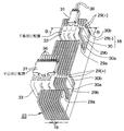
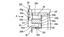
図4〜図8に示すように、スタック23のうちセル電圧モニター31が取付けられる部位には、樹脂フレーム30に第1の溝30aと第2の溝30bが形成されている。第1の溝30aと第2の溝30bとは離れた位置に形成されており互いに平行である。プラス極の金属板29とマイナス極の金属板29とのうち何れか一方の金属板29に端子31が接触される。端子31が接触される方の金属板29には、樹脂フレーム30の第1の溝30aのみと位置、形状を対応させて狭幅の溝29aが形成されており、端子31が接触されない方の金属板29には、樹脂フレーム30の第1の溝30aと第2の溝30bの両方にわたる広幅の溝29bが形成されている。
【0017】
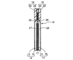
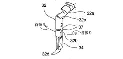
端子32は、導線36に接続されている。端子32は、側面視でL字状のL字状部材からなり、L字の第1の脚32aと、L字の第2の脚32bと、L字の折れ曲がり部32cとを有する。端子32は、第1の脚32aでかしめによって導線36に連結される。端子32の第2の脚32bは折れ曲がり部32cと反対側の端部に一対のアーム32dを有し、一対のアーム32d間にセパレータの金属板29を挟んで金属板29と接触し、金属板29とのコンタクト部(電気的接触部)34を構成している。
【0018】
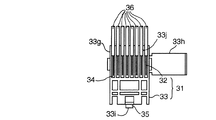
ハウジング33は、側面視でF字状のF字状部材からなり、F字の柱33aと、柱33aの先端33dから柱33aと直交方向に延びる第1の脚33bと、柱33aの中間部33eから柱33aと直交方向に延びる第2の脚33cとを有する。
セル電圧モニター31がスタック23に取付けられた時には、ハウジング33の第1の脚33bは樹脂フレーム30に第1の溝30aと金属板29の溝29aに突入し、ハウジング33の第2の脚33cは樹脂フレーム30に第2の溝30bと金属板29の溝29bに突入する。
【0019】
ハウジング33の柱33aの、先端33dと反対側の端部33fから中間部33eまでの間の部分、および第2の脚33cとは、端子32を保持する端子保持部33gを構成する。端子32を端子保持部33gに挿入後ハウジング33の蓋33hを閉じて端子32が端子保持部33gから抜け出ないようにする。
また、ハウジング33の第1の脚33bには、第2の脚33cに対向する側と反対側の面に該面から突出する爪33iが形成されている。爪33iは、樹脂フレーム30の第1の溝30aの、爪対応部に形成された爪係合凹部30cに入り、爪係合凹部30cと係合し、爪33iと爪係合凹部30cはセル電圧モニター31の燃料電池に固定する固定部35を構成している。
金属板29の溝29a、29bの、ハウジング33の第1の脚33bに対向する縁部は、樹脂フレーム30の第1の溝30aの、ハウジング33の第1の脚33bに対向する縁部よりも、第1の脚33bから離れていて爪33iと当たらず、爪33iが爪係合凹部30cに入ることを阻害しない。
【0020】
端子32には、一対のアーム32dと折れ曲がり部32cとの間に、スリット37が形成されていて、第1の脚32aが一対のアーム32dに対してセル積層方向に若干首振りすることができるようになっている。これによって、セルの厚さ方向の寸法に誤差があっても、それを吸収して端子32を取付けることができるようにしてある。このスリット37があっても、セル数が多くなると寸法誤差が積算されて大きな誤差となってその誤差を吸収できなくなるので、1つのハウジング33に保持される端子32の数は約10以下とすることが望ましい。
【0021】
また、図4に示すように、ハウジング33は、スタック23のセル積層方向に左右互い違いに配置されて、千鳥配置となっている。燃料電池スタック23の各セルには、ハウジング33の千鳥状の配置の左右の両方の列に対して、セル電圧モニター31を取り付けるためのセル電圧モニター取付け部が設けられている。各セル電圧モニター取付け部は、樹脂フレーム30の第1の溝30a、第2の溝30b、爪係合凹部30c、金属板29の2つの溝29a、29bを含む。セルには、千鳥配置の左列か右列かのハウジング33が取付けられ固定されるが、ハウジング33が取付けられる方の列に対応する部位にはセル電圧モニター取付け部が形成されことは勿論であるが、ハウジングが取付けられない方の列に対応する部位にも、セル電圧モニター取付け部が形成されている。これによって、左右列2つのセル電圧モニター取付け部がいずれのセルにも形成され、いずれのセルも、2つのセル電圧モニター取付け部が形成された構造をとる。その結果、セル電圧モニター取付けに1種類のセルを用意すればよく、従来のように左列の端子が取付けられるセルと右列の端子が取付けられるセルとの構造を変えて2種類のセルを用意する必要がなくなる。
【0022】
つぎに、本発明の燃料電池のセパレータの作用を説明する。
まず、セパレータ18の金属板29の表面処理を、ガス流路部40とセル電圧モニター端子接触部42とで変えたので、ガス流路部40には耐食性のある表面処理を施し、セル電圧モニター端子接触部42には接触抵抗を少なくし、かつ、安定化させる表面処理を施すことにより、ガス流路部40の耐食性を良好に維持しながら、端子接触部42の接触抵抗を安定させることができる。その結果、端子接触部42の接触抵抗の安定と、ガス流路部40の耐食性とを容易に両立させることができる。
【0023】
具体的には、セパレータ18の金属板29のガス流路部40の表面処理はカーボンコートを含み、セパレータ18の金属板29のセル電圧モニター端子との接触部42の表面処理はカーボンコートを含まないようにしたので、ガス流路部40の耐食性を良好に維持しながら、端子接触部42の接触抵抗を安定させることができる。その結果、端子接触部42の接触抵抗の安定と、ガス流路部40の耐食性とを容易に両立させることができる。
セパレータ18の金属板29は、たとえばステンレス板のガス流路部表面に金メッキしたものからなるが、ガス流路部40は、とくに酸化ガス流路28が形成されているガス流路部40は、生成水と酸素に触れるので、酸化しやすい環境にあり、もしも金メッキにピンホールがあると、ステンレス素地の腐食が進行しやすいので、カーボンコートを施してメッキ層のピンホールを埋め、耐食性を向上させる。しかし、カーボンコートを施すと表面の凹凸等により、金属板29の端子接触部42の接触抵抗が安定しにくくなり、検出電位の精度が低下する。本発明では、金属板29の端子接触部42はカーボンコートを施さず、導電性金属メッキ、とくに金メッキのままとしたので、端子接触部42の接触抵抗が安定し、検出電位の精度が向上する。
【0024】
【発明の効果】
請求項1〜3の燃料電池のセパレータによれば、ガス流路部では、金属板に金属メッキが施されるとともに該金属メッキの上にカーボンコートが施されており、ガス流路部外のセル電圧モニター端子との接触部では、カーボンコート時に前記セル電圧モニター端子との接触部をマスキングすることにより、金属板に金属メッキが施されたままとされているので、ガス流路部には耐食性のある表面処理を施し、セル電圧モニター端子接触部には接触抵抗を少なくし、かつ、安定化させる表面処理を施すことにより、ガス流路部の耐食性を良好に維持しながら、端子接触部の接触抵抗を安定させることができる。その結果、端子接触部の接触抵抗の安定と、ガス流路部の耐食性とを容易に両立させることができる。
ガス流路部の表面処理はカーボンコートを含み、セル電圧モニター端子との接触部の表面処理は金属メッキのままでカーボンコートを含まないようにしたので、ガス流路部の耐食性を良好に維持しながら、端子接触部の接触抵抗を安定させることができる。その結果、端子接触部の接触抵抗の安定と、ガス流路部の耐食性とを容易に両立させることができる。
【図面の簡単な説明】
【図1】燃料電池スタックの、セル積層方向と直交する方向から見た、側面図である。
【図2】燃料電池スタックの単セルの一部分の断面図である。
【図3】本発明の燃料電池のセパレータの正面図である。
【図4】本発明の燃料電池のセパレータが組み付けられたスタックへのセル電圧モニター取付け構造の斜視図である。
【図5】図4のB−B線で切断して見た断面図である。
【図6】図4のセル電圧モニター取付け構造の側面図である。
【図7】図6のうちセル電圧モニターの、図6におけるA方向視図である。
【図8】図6のうちセル電圧モニターの、端子のみの斜視図である。
【符号の説明】
10 (固体高分子電解質型)燃料電池
11 電解質膜
12、15 触媒層
13、16 拡散層
14 電極(アノード、燃料極)
17 電極(カソード、空気極)
18 セパレータ
19 セル
20 ターミナル
21 インシュレータ
22 エンドプレート
23 スタック
24 締結部材(テンションプレート)
25 ボルト
26 冷媒流路(冷却水流路)
27 燃料ガス流路
28 酸化ガス流路
29 金属板
29a、29b 溝
30 樹脂フレーム
30a 第1の溝
30b 第2の溝
30c 爪係合凹部
31 セル電圧モニター
32 端子
32a 第1の脚
32b 第2の脚
32c 折れ曲がり部
32d 一対のアーム
33 ハウジング
33a 柱
33b 第1の脚
33c 第2の脚
33d 先端
33e 中間部
33f 反対側端部
33g 端子保持部
33h 蓋
33i 爪
33j 仕切板
34 コンタクト部
35 抜け止め部
36 導線
37 スリット
40 ガス流路部40
41 ガス流路部外の部分
42 セル電圧モニター端子との接触部[0001]
BACKGROUND OF THE INVENTION
The present invention relates to a separator for a low temperature fuel cell, particularly a solid polymer electrolyte fuel cell, and to a surface treatment structure for a metal plate of the separator.
[0002]
[Prior art]
A solid polymer electrolyte fuel cell includes a laminate of a membrane-electrode assembly (MEA) and a separator. The membrane-electrode assembly includes an electrolyte membrane composed of an ion exchange membrane, an electrode composed of a catalyst layer disposed on one surface of the electrolyte membrane (anode, fuel electrode), and an electrode composed of a catalyst layer disposed on the other surface of the electrolyte membrane ( Cathode, air electrode). Between the membrane-electrode assembly and the separator, diffusion layers are provided on the anode side and the cathode side, respectively. In the separator, a fuel gas passage for supplying fuel gas (hydrogen) to the anode is formed, and an oxidizing gas passage for supplying oxidizing gas (oxygen, usually air) to the cathode. The separator is also formed with a refrigerant flow path for flowing a refrigerant (usually cooling water). A cell is formed by stacking a membrane-electrode assembly and a separator, a module is formed from at least one cell, a module is stacked to form a cell stack, and terminals, insulators, end plates are formed at both ends of the cell stack in the cell stacking direction. The cell stack is clamped in the cell stacking direction, and fixed by fastening members (for example, tension plates), bolts, and nuts extending in the cell stacking direction outside the cell stack.
In each cell, a reaction for converting hydrogen into hydrogen ions (protons) and electrons is performed on the anode side, and the hydrogen ions move through the electrolyte membrane to the cathode side. On the cathode side, oxygen, hydrogen ions, and electrons (neighboring MEA) Next, the following reaction is performed to generate water from electrons generated at the anode of the first electrode through the separator or electrons generated at the anode of the cell at one end in the cell stacking direction through the external circuit to the cathode of the other cell.
Anode side: H 2 → 2H + + 2e −
Cathode side: 2H + + 2e − + (1/2) O 2 → H 2 O
Confirm that normal power generation is performed in each cell or every multiple cells, control the flow rate of the reaction gas based on the cell voltage, and guide the motor in case of abnormal voltage In order to apply, the cell voltage is monitored.
Japanese Patent Application Laid-Open No. 11-339828 discloses a cell voltage monitor for a fuel cell. Japanese Patent Laid-Open No. 2001-283880 discloses that a carbon coat is applied to the entire metal separator in order to improve the corrosion resistance of the gas flow path portion of the metal separator.
[0003]
[Problems to be solved by the invention]
However, the prior art has the following problems.
When the carbon coat is applied to the cell voltage monitor terminal contact portion of the metal separator, the contact resistance of the metal contact of the terminal contact portion becomes unstable, and the cell voltage detection accuracy decreases. Moreover, if the carbon coat is not applied, the progress of corrosion of the gas flow path portion is accelerated. Therefore, it is difficult to achieve both stable contact resistance of the terminal contact portion and corrosion resistance of the gas flow path portion.
The objective of this invention is providing the separator of a fuel cell which can stabilize the contact resistance of a terminal contact part, without reducing the corrosion resistance of a gas flow path part.
[0004]
[Means for Solving the Problems]
The present invention for achieving the above object is as follows.
(1) It has a metal plate, and the metal plate is a separator for a fuel cell having a gas channel part and a contact part with a cell voltage monitor terminal outside the gas channel part,
In the gas flow path section, the metal plate is subjected to metal plating and a carbon coat is applied to the metal plating.
In the contact portion with the cell voltage monitor terminal outside the gas flow path portion, the metal plate is left subjected to the metal plating by masking the contact portion with the cell voltage monitor terminal during carbon coating. Fuel cell separator.
(2) The fuel cell separator according to (1), wherein the metal plate is a stainless steel plate, and the metal plating is gold plating.
(3) The fuel cell separator according to (1), wherein the gas flow path portion is sealed with a sealing material, and the outside of the sealing material is outside the gas flow path portion.
[0005]
In the fuel cell separators of the above (1) to (3) , the gas flow path portion is subjected to metal plating and a carbon coat is applied to the metal plating, so that the cell voltage outside the gas flow path portion. At the contact portion with the monitor terminal, the metal plate is left with metal plating by masking the contact portion with the cell voltage monitor terminal at the time of carbon coating . By applying a certain surface treatment and reducing the contact resistance to the cell voltage monitor terminal contact part and stabilizing the surface treatment, the contact of the terminal contact part is maintained while maintaining good corrosion resistance of the gas flow path part. Resistance can be stabilized. As a result, the stability of the contact resistance of the terminal contact portion and the corrosion resistance of the gas flow path portion can be easily achieved.
Surface treatment of the gas flow path unit includes a carbon coating, the surface treatment of the contact portion between the cell voltage monitor terminal was free of carbon coating remains metal plating, good corrosion resistance of the gas flow path portion The contact resistance of the terminal contact portion can be stabilized while maintaining. As a result, the stability of the contact resistance of the terminal contact portion and the corrosion resistance of the gas flow path portion can be easily achieved.
[0006]
DETAILED DESCRIPTION OF THE INVENTION
Below, the separator of the fuel cell of this invention is demonstrated with reference to FIGS.
The target fuel cell in the present invention is a low-temperature fuel cell, for example, a solid polymer
[0007]
As shown in FIGS. 1 and 2, the solid polymer
The membrane-electrode assembly and the
[0008]
The
The
As shown in FIG. 3, the
[0009]
The MEA is sandwiched between the plus-
There is a potential difference between the plus side metal plate and the minus side metal plate facing each other with the
[0010]
A plurality of cell voltage monitors 31 are attached to the
Each cell voltage monitor 31 includes one
One or
A plurality of
The number of poles of the cell voltage monitor 31 is equal to the number of
[0011]
Each
[0012]
As shown in FIG. 1, the
The
[0013]
In the
The
The surface treatment of the gas
[0014]
The
[0015]
Further, when carbon coating is applied also to the
[0016]
The cell voltage monitor 31 is attached to the
As shown in FIGS. 4 to 8, a
[0017]
The terminal 32 is connected to the
[0018]
The
When the cell voltage monitor 31 is attached to the
[0019]
The portion of the
Further, the
Edges of the
[0020]
In the terminal 32, a
[0021]
Further, as shown in FIG. 4, the
[0022]
Next, the operation of the fuel cell separator of the present invention will be described.
First, since the surface treatment of the
[0023]
Specifically, the surface treatment of the gas
The
[0024]
【The invention's effect】
According to the fuel cell separator of claims 1 to 3 , in the gas flow path portion, the metal plate is subjected to metal plating and the metal plating is applied to the metal plating. In the contact part with the cell voltage monitor terminal, the metal plate is kept plated by masking the contact part with the cell voltage monitor terminal at the time of carbon coating. By applying a surface treatment with corrosion resistance and reducing the contact resistance to the cell voltage monitor terminal contact portion and stabilizing the surface treatment, the contact portion of the terminal is maintained while maintaining good corrosion resistance of the gas flow path portion. The contact resistance can be stabilized. As a result, the stability of the contact resistance of the terminal contact portion and the corrosion resistance of the gas flow path portion can be easily achieved.
Surface treatment of the gas flow path unit includes a carbon coating, the surface treatment of the contact portion between the cell voltage monitor terminal was free of carbon coating remains metal plating, good corrosion resistance of the gas flow path portion The contact resistance of the terminal contact portion can be stabilized while maintaining. As a result, the stability of the contact resistance of the terminal contact portion and the corrosion resistance of the gas flow path portion can be easily achieved.
[Brief description of the drawings]
FIG. 1 is a side view of a fuel cell stack as viewed from a direction orthogonal to a cell stacking direction.
FIG. 2 is a cross-sectional view of a part of a single cell of a fuel cell stack.
FIG. 3 is a front view of a separator of a fuel cell according to the present invention.
FIG. 4 is a perspective view of a structure for attaching a cell voltage monitor to a stack in which a separator of a fuel cell of the present invention is assembled.
5 is a cross-sectional view taken along line BB in FIG.
6 is a side view of the cell voltage monitor mounting structure of FIG. 4. FIG.
7 is a view in the A direction in FIG. 6 of the cell voltage monitor in FIG. 6;
FIG. 8 is a perspective view of only the terminal of the cell voltage monitor in FIG. 6;
[Explanation of symbols]
10 (Solid Polymer Electrolyte Type)
17 electrodes (cathode, air electrode)
18
25
27
41 Portion outside gas
Claims (3)
前記ガス流路部では、前記金属板に金属メッキが施されるとともに該金属メッキの上にカーボンコートが施されており、
前記ガス流路部外の前記セル電圧モニター端子との接触部では、カーボンコート時に前記セル電圧モニター端子との接触部をマスキングすることにより、前記金属板に前記金属メッキが施されたままとされている燃料電池のセパレータ。 A metal plate, the metal plate is a separator for a fuel cell having a gas channel portion and a contact portion with a cell voltage monitor terminal outside the gas channel portion,
In the gas flow path section, the metal plate is subjected to metal plating and a carbon coat is applied to the metal plating.
In the contact portion with the cell voltage monitor terminal outside the gas flow path portion, the metal plate is left subjected to the metal plating by masking the contact portion with the cell voltage monitor terminal during carbon coating. Fuel cell separator.
Priority Applications (4)
| Application Number | Priority Date | Filing Date | Title |
|---|---|---|---|
| JP2002233621A JP3891069B2 (en) | 2002-08-09 | 2002-08-09 | Fuel cell separator |
| US10/629,764 US7459228B2 (en) | 2002-08-09 | 2003-07-30 | Separator for fuel cell including a terminal of a cell voltage monitor |
| CA2436562A CA2436562C (en) | 2002-08-09 | 2003-08-06 | Separator for fuel cell |
| DE10336510A DE10336510B4 (en) | 2002-08-09 | 2003-08-08 | Separator for fuel cell and fuel cell stack |
Applications Claiming Priority (1)
| Application Number | Priority Date | Filing Date | Title |
|---|---|---|---|
| JP2002233621A JP3891069B2 (en) | 2002-08-09 | 2002-08-09 | Fuel cell separator |
Publications (2)
| Publication Number | Publication Date |
|---|---|
| JP2004079193A JP2004079193A (en) | 2004-03-11 |
| JP3891069B2 true JP3891069B2 (en) | 2007-03-07 |
Family
ID=31185140
Family Applications (1)
| Application Number | Title | Priority Date | Filing Date |
|---|---|---|---|
| JP2002233621A Expired - Fee Related JP3891069B2 (en) | 2002-08-09 | 2002-08-09 | Fuel cell separator |
Country Status (4)
| Country | Link |
|---|---|
| US (1) | US7459228B2 (en) |
| JP (1) | JP3891069B2 (en) |
| CA (1) | CA2436562C (en) |
| DE (1) | DE10336510B4 (en) |
Cited By (2)
| Publication number | Priority date | Publication date | Assignee | Title |
|---|---|---|---|---|
| WO2009054366A1 (en) * | 2007-10-23 | 2009-04-30 | Toyota Jidosha Kabushiki Kaisha | Fuel cell separator manufacturing method and fuel cell manufacturing method |
| DE112008003032T5 (en) | 2007-11-12 | 2010-09-02 | Toyota Jidosha Kabushiki Kaisha, Toyota-shi | Method for producing a fuel cell separator |
Families Citing this family (21)
| Publication number | Priority date | Publication date | Assignee | Title |
|---|---|---|---|---|
| KR101127028B1 (en) | 2003-11-19 | 2012-03-26 | 아쿠아훼아리 가부시키가이샤 | Fuel cell |
| US7153600B2 (en) * | 2004-02-24 | 2006-12-26 | General Motors Corporation | Integrated cell voltage monitoring module |
| FR2887690B1 (en) * | 2005-06-28 | 2007-09-14 | Peugeot Citroen Automobiles Sa | BIPOLAR PLATE FOR FUEL CELL COMPRISING HOUSING FOR MEASURING CONNECTOR |
| FR2887689B1 (en) * | 2005-06-28 | 2007-09-21 | Peugeot Citroen Automobiles Sa | BIPOLAR PLATE FOR FUEL CELL COMPRISING A CONNECTION CHANNEL |
| DE102005032467A1 (en) * | 2005-07-08 | 2007-01-11 | Volkswagen Ag | Contact arrangement for fuel cell stack electrodes has contacts of different electrical polarities spaced at surround perpendicular to stack direction |
| JP5034273B2 (en) * | 2006-03-07 | 2012-09-26 | トヨタ自動車株式会社 | Fuel cell |
| JP5011759B2 (en) * | 2006-03-07 | 2012-08-29 | トヨタ自動車株式会社 | Fuel cell with cell voltage monitor |
| JP4910461B2 (en) * | 2006-04-13 | 2012-04-04 | トヨタ自動車株式会社 | Fluid introduction member for fuel cell stack and fuel cell stack |
| US7361065B1 (en) * | 2006-11-03 | 2008-04-22 | Tyco Electronics Corporation | Connector assembly for conductive plates |
| JP5233181B2 (en) * | 2007-06-27 | 2013-07-10 | トヨタ自動車株式会社 | Fuel cell |
| JP4434264B2 (en) | 2007-11-05 | 2010-03-17 | トヨタ自動車株式会社 | Fuel cell, fuel cell manufacturing method and fuel cell gas flow channel structure |
| JP5307441B2 (en) * | 2008-04-22 | 2013-10-02 | 本田技研工業株式会社 | Fuel cell stack |
| JP5188459B2 (en) * | 2009-06-10 | 2013-04-24 | 本田技研工業株式会社 | Fuel cell stack |
| US9502731B2 (en) * | 2010-11-18 | 2016-11-22 | GM Global Technology Operations LLC | Fuel cell plate features to resolve differences in component tolerances |
| JP5728283B2 (en) * | 2011-04-22 | 2015-06-03 | 本田技研工業株式会社 | Fuel cell |
| JP5604361B2 (en) * | 2011-04-22 | 2014-10-08 | 本田技研工業株式会社 | Fuel cell |
| GB2506927A (en) * | 2012-10-15 | 2014-04-16 | Intelligent Energy Ltd | Cell voltage monitoring connector system for a fuel cell stack |
| DE102013013295A1 (en) * | 2013-08-12 | 2015-02-12 | Airbus Defence and Space GmbH | Ion dosing device for an energy storage device, method for manufacturing an ion dosing device and energy storage device |
| JP6569582B2 (en) * | 2016-04-11 | 2019-09-04 | トヨタ自動車株式会社 | Manufacturing method of fuel cell separator |
| JP6568011B2 (en) * | 2016-04-28 | 2019-08-28 | トヨタ自動車株式会社 | Surface treatment method of separator material for fuel cell |
| DE102016225438B4 (en) * | 2016-12-19 | 2026-03-05 | Bayerische Motoren Werke Aktiengesellschaft | Connecting element for electrically contacting separator plates of a fuel cell stack |
Family Cites Families (16)
| Publication number | Priority date | Publication date | Assignee | Title |
|---|---|---|---|---|
| JP3141908B2 (en) * | 1993-03-24 | 2001-03-07 | 株式会社エクォス・リサーチ | Fuel cell temperature controller |
| JPH09139218A (en) * | 1995-11-14 | 1997-05-27 | Ishikawajima Harima Heavy Ind Co Ltd | Molten carbonate fuel cell separator and method of manufacturing the same |
| JP3854682B2 (en) * | 1997-02-13 | 2006-12-06 | アイシン高丘株式会社 | Fuel cell separator |
| US5858569A (en) * | 1997-03-21 | 1999-01-12 | Plug Power L.L.C. | Low cost fuel cell stack design |
| WO1999019927A1 (en) * | 1997-10-14 | 1999-04-22 | Nisshin Steel Co., Ltd. | Separator for low temperature type fuel cell and method of production thereof |
| JP4707786B2 (en) * | 1998-05-07 | 2011-06-22 | トヨタ自動車株式会社 | Manufacturing method of gas separator for fuel cell |
| JP4069494B2 (en) * | 1998-05-29 | 2008-04-02 | アイシン精機株式会社 | Fuel cell stack with cell voltage measurement terminal |
| JPH11354142A (en) * | 1998-06-11 | 1999-12-24 | Toshiba Corp | Solid polymer electrolyte fuel cell |
| JP3468739B2 (en) | 1999-12-27 | 2003-11-17 | 新東ブレーター株式会社 | Method for attaching metal having high corrosion resistance and low contact resistance to carbon to fuel cell separator |
| JP4087039B2 (en) * | 2000-03-14 | 2008-05-14 | 本田技研工業株式会社 | Fuel cell |
| JP2001283880A (en) | 2000-03-30 | 2001-10-12 | Nisshin Steel Co Ltd | Low temperature fuel cell separator and method for producing the same |
| US6724194B1 (en) * | 2000-06-30 | 2004-04-20 | Ballard Power Systems Inc. | Cell voltage monitor for a fuel cell stack |
| JP4493836B2 (en) * | 2000-12-18 | 2010-06-30 | 本田技研工業株式会社 | Cell voltage detection device for fuel cell |
| US7682714B2 (en) * | 2001-05-25 | 2010-03-23 | Toyota Jidosha Kabushiki Kaisha | Connecting structure of a cell monitor connector to a fuel cell stack |
| JP2002358993A (en) * | 2001-05-31 | 2002-12-13 | Mitsubishi Electric Corp | Stacked fuel cell and method for measuring cell voltage |
| JP3868784B2 (en) * | 2001-10-02 | 2007-01-17 | 本田技研工業株式会社 | Fuel cell |
-
2002
- 2002-08-09 JP JP2002233621A patent/JP3891069B2/en not_active Expired - Fee Related
-
2003
- 2003-07-30 US US10/629,764 patent/US7459228B2/en not_active Expired - Fee Related
- 2003-08-06 CA CA2436562A patent/CA2436562C/en not_active Expired - Fee Related
- 2003-08-08 DE DE10336510A patent/DE10336510B4/en not_active Expired - Fee Related
Cited By (2)
| Publication number | Priority date | Publication date | Assignee | Title |
|---|---|---|---|---|
| WO2009054366A1 (en) * | 2007-10-23 | 2009-04-30 | Toyota Jidosha Kabushiki Kaisha | Fuel cell separator manufacturing method and fuel cell manufacturing method |
| DE112008003032T5 (en) | 2007-11-12 | 2010-09-02 | Toyota Jidosha Kabushiki Kaisha, Toyota-shi | Method for producing a fuel cell separator |
Also Published As
| Publication number | Publication date |
|---|---|
| JP2004079193A (en) | 2004-03-11 |
| CA2436562A1 (en) | 2004-02-09 |
| DE10336510B4 (en) | 2005-11-24 |
| CA2436562C (en) | 2012-04-17 |
| US20040028969A1 (en) | 2004-02-12 |
| DE10336510A1 (en) | 2004-02-26 |
| US7459228B2 (en) | 2008-12-02 |
Similar Documents
| Publication | Publication Date | Title |
|---|---|---|
| JP3891069B2 (en) | Fuel cell separator | |
| US7625657B2 (en) | Fuel cell and fuel cell stack | |
| US7323269B2 (en) | Fuel cell | |
| JP4098582B2 (en) | Fuel cell with cell voltage monitor | |
| KR101941739B1 (en) | Fuel cell stack | |
| US20060024561A1 (en) | Fuel cell stack | |
| CN101375451B (en) | Fuel cell stack with high flood resistance | |
| JP2004079192A (en) | Mounting structure of cell voltage monitor to fuel cell stack | |
| JP2002124285A5 (en) | ||
| JP2002124285A (en) | Fuel cell voltage measuring device | |
| JP2007087766A (en) | Fuel cell stack | |
| JP4211317B2 (en) | Cell voltage monitor | |
| US7722977B2 (en) | Fuel cell stack comprising current collector provided at least at one fluid passage | |
| JP3870719B2 (en) | Fuel cell having connection structure of cell voltage monitoring connector to cell | |
| US7846589B2 (en) | Fuel cell having separator with cell voltage terminal | |
| JP4595476B2 (en) | Fuel cell | |
| JP5034273B2 (en) | Fuel cell | |
| JP4726182B2 (en) | Fuel cell stack | |
| JP4134615B2 (en) | Fuel cell | |
| JP2006100021A (en) | Fuel cell stack | |
| JP2005293924A (en) | Cell voltage monitoring device for fuel cell and its mounting method to fuel cell stack | |
| JP2003297395A (en) | Fuel cell | |
| JP2006140166A (en) | Fuel cell monitoring device | |
| JP2006140166A5 (en) | ||
| JP3788273B2 (en) | Fuel cell having cell monitor mounting structure |
Legal Events
| Date | Code | Title | Description |
|---|---|---|---|
| A621 | Written request for application examination |
Free format text: JAPANESE INTERMEDIATE CODE: A621 Effective date: 20050316 |
|
| A977 | Report on retrieval |
Free format text: JAPANESE INTERMEDIATE CODE: A971007 Effective date: 20060815 |
|
| A131 | Notification of reasons for refusal |
Free format text: JAPANESE INTERMEDIATE CODE: A131 Effective date: 20060822 |
|
| A521 | Request for written amendment filed |
Free format text: JAPANESE INTERMEDIATE CODE: A523 Effective date: 20061023 |
|
| TRDD | Decision of grant or rejection written | ||
| A01 | Written decision to grant a patent or to grant a registration (utility model) |
Free format text: JAPANESE INTERMEDIATE CODE: A01 Effective date: 20061114 |
|
| A61 | First payment of annual fees (during grant procedure) |
Free format text: JAPANESE INTERMEDIATE CODE: A61 Effective date: 20061127 |
|
| FPAY | Renewal fee payment (event date is renewal date of database) |
Free format text: PAYMENT UNTIL: 20101215 Year of fee payment: 4 |
|
| FPAY | Renewal fee payment (event date is renewal date of database) |
Free format text: PAYMENT UNTIL: 20101215 Year of fee payment: 4 |
|
| FPAY | Renewal fee payment (event date is renewal date of database) |
Free format text: PAYMENT UNTIL: 20111215 Year of fee payment: 5 |
|
| LAPS | Cancellation because of no payment of annual fees |