JP3887273B2 - Fuel tank connector - Google Patents
Fuel tank connector Download PDFInfo
- Publication number
- JP3887273B2 JP3887273B2 JP2002165961A JP2002165961A JP3887273B2 JP 3887273 B2 JP3887273 B2 JP 3887273B2 JP 2002165961 A JP2002165961 A JP 2002165961A JP 2002165961 A JP2002165961 A JP 2002165961A JP 3887273 B2 JP3887273 B2 JP 3887273B2
- Authority
- JP
- Japan
- Prior art keywords
- fuel tank
- connector
- gas barrier
- fuel
- cylindrical
- Prior art date
- Legal status (The legal status is an assumption and is not a legal conclusion. Google has not performed a legal analysis and makes no representation as to the accuracy of the status listed.)
- Expired - Fee Related
Links
Images


Landscapes
- Cooling, Air Intake And Gas Exhaust, And Fuel Tank Arrangements In Propulsion Units (AREA)
- Branch Pipes, Bends, And The Like (AREA)
Description
【0001】
【発明の属する技術分野】
この発明は、燃料タンク用コネクタ、特に、燃料タンクからの燃料蒸発ガスの漏れ出しを効果的に減少させるようにしたコネクタの提供に関する。
【0002】
【従来の技術】
燃料タンク100には、通例、燃料の供給管や、燃料から生ずるガスを案内する管101などが該タンク100に接続して備えられている。
かかる各種の管101は、図23及び図24で示されるように当該燃料タンク100に備えられるコネクタ110によって接続されている。
【0003】
この図23及び図24で示されるコネクタ110は、管101の接続される管状部111と、この管状部111における一端部側の外周部から側方に突き出すように備えられていると共に該タンク100における開口100a上を覆うように該タンク100面に溶着される鍔状部112と、前記管状部111と反対側の該鍔状部112に備えられているフューエルカットオフバルブ113とを有する構成としてあり、前記管状部111と鍔状部112とが高密度ポリエチレンによって一体に成形してある。
【0004】
また、この図示例に係るコネクタ110における前記フューエルカットオフバルブ113は、前記管状部111における孔に連通する孔の開口部分に弁座113a’を備えた弁座体113aを有する下面開口のポリアセタールからなる筒状をなすフロート室構成箱状部113bと、上部に弁体部113eを一体に有すると共に該箱状部113b内に上下動可能に納め入れられるフロート113cと、該箱状部113bの下面側の開口を塞いで、該箱状部113bと共に該フロート113cの組み入れられるフロート室を構成する蓋体113dとを備えた構成としてあり、前記フロート113cの上昇に伴って、前記弁座113a’に前記フロート113cの前記弁体部113eが密に接して閉弁される構成としてある。
【0005】
かかるコネクタ110は、前記フューエルカットオフバルブ113における箱状部113bを成形金型内にインサートした状態でなされるプラスチック成形などによって、該箱状部113bの上部側を前記鍔状部112内に埋め付け状態にして該箱状部113bを該鍔状部112に一体に備えた構成としてあると共に、この箱状部113bの備えられている前記鍔状部112の外周部分を、前記タンク100の開口100aから該箱状部113bを該タンク100内に差入れた状態で、該タンク100の開口縁周側方にある当該タンク100面部に溶着した構成としてある。
【0006】
【発明が解決しようとする課題】
このように構成されるコネクタ110にあっては、前記コネクタ110を構成する鍔状部112と管状部111とが高密度ポリエチレンによって構成されていることから、前記タンク100の開口100aの開口縁と、このタンク100に溶着備えられたコネクタ110における前記箱状部113bとの間に備えられる当該コネクタ110における鍔状部112部分を通して、該タンク100内などにおいて生ずる燃料からの蒸発ガスが、規制値以内ではあるが、該タンク100外に漏れ出すことが予想された。
【0007】
この発明は、かかる従来のコネクタにおいて予想される燃料タンクからの燃料蒸発ガスの漏れ出しを効果的に減少させるようにした成形容易なコネクタの提供を目的としている。
【0008】
【課題を解決するための手段】
この発明は前記の目的を達成するために、請求項1記載の発明を、燃料タンクの開口部に備え付けられて該燃料タンクと該燃料タンクに接続される管とを連通状態に接続するコネクタであって、
該コネクタが、筒状部と、該筒状部の外周側に備えられ且つ前記燃料タンクの開口よりも大きい面を有する鍔状部とを備えたガスバリヤ性合成樹脂製のガスバリヤ体を備えて構成してあると共に、
該ガスバリヤ体が、
ポリブチレンテレフタレート製、
ポリフェニレンスルフィド製、
リキッドクリスタルポリマ製、
脂肪族ポリケトン製、
芳香族ポリアミド製、
エチレン−ビニルアルコール共重合体と高密度ポリエチレンとのブレンドポリマー製、
ポリアミドとポリエチレンとのブレンドポリマー製、
ポリアミドと高密度ポリエチレンとのブレンドポリマー製、
又は、ポリエチレンテレフタレート製であり、
しかも、前記ガスバリヤ体の表面の少なくとも一部が接着性オレフィン樹脂、ポリエチレン又は高密度ポリエチレン製の外殻体部で覆われていると共に、
この外殻体部が、当該ガスバリア体の鍔状部の先端を覆って前記燃料タンクの外面部に向けて突き出す環状突き出し部を有しており、
さらに、前記ガスバリア体の鍔状部の先端側に前記燃料タンクの外面部に向けて、前記ポリエチレン又は高密度ポリエチレン製の外殻体部の環状突き出し部とほぼ同じ寸法分突き出された環状突出し部が備えられていると共に、
このガスバリア体の環状突き出し部と前記ポリエチレン又は高密度ポリエチレン製の外殻体部の環状突き出し部との間に、前記燃料タンクの外面部側において開放された空隙が形成してあることを特徴とする燃料タンク用コネクタとしてある。
【0009】
このように構成される燃料タンク用コネクタにあっては、前記燃料タンク内にもたらされる燃料からの蒸発ガスが、当該コネクタ部分から漏れ出すのを効果的に減じることができる。
【0010】
また、一体に外殻体部を備えられたガスバリヤ体を、当該外殻体部において燃料タンクに対して、確実且つ容易に溶着して備え付けることができる。
【0011】
特に、前記燃料からの蒸発ガスの当該燃料タンクからの漏れ出しを前記ガスバリヤ体によって効果的に減じながら、燃料タンクの表面側層を高密度ポリエチレンとした燃料タンクに対して前記外殻体部の環状突き出し部によって溶着強度を高く確保させた状態でコネクタを取り付けることができる。
【0012】
前記外殻体部の環状突き出し部を加熱溶融させた際に、かかる溶融された環状突き出し部を構成するポリエチレン又は高密度ポリエチレンを前記空隙に入り込ませることができることから、これにより溶融された当該ポリエチレン又は高密度ポリエチレンを広い範囲に押し広げさせた状態で燃料タンクに当該環状突き出し部を溶着させることができる。
【0013】
また、前記外殻体部の環状突き出し部を燃料タンクに溶着させた後も、前記空隙が残されるように当該溶着を行うことにより、燃料ないし燃料からの蒸発ガスによってガスバリア体が膨潤してもこの残された空隙によってこの膨潤分を吸収して、外殻体部の環状突き出し部と燃料タンクとの溶着箇所にこの溶着強度を低下させるような力が作用され難いようにすることができる。
【0014】
また、前記目的を達成するために、請求項2に記載の発明を、前記請求項1に記載の発明において、前記コネクタが、燃料供給管の接続用コネクタであることを特徴とする燃料タンク用コネクタとしてある。
【0015】
このように構成される燃料タンク用コネクタにあっては、前記特長に併せて、燃料から生ずる蒸発ガスの漏洩を効果的に減じた状態で、燃料供給管を燃料タンクに接続することができる。
【0016】
また、前記目的を達成するために、請求項3に記載の発明を、前記請求項1に記載の発明において、前記コネクタが、通気管の接続用コネクタであることを特徴とする燃料タンク用コネクタとしてある。
【0017】
このように構成される燃料タンク用コネクタにあっては、前記特長に併せて、燃料から生ずる蒸発ガスの漏洩を効果的に減じた状態で、通気管を燃料タンクに接続することができる。
【0018】
また、前記目的を達成するために、請求項4に記載の発明を、前記請求項1に記載の発明において、前記コネクタがフューエルカットオフバルブを備えていることを特徴とする燃料タンク用コネクタとしてある。
【0019】
このように構成される燃料タンク用コネクタにあっては、前記特長に併せて、燃料から生ずる蒸発ガスの漏洩を効果的に減じた状態で、管と燃料タンクとをフューエルカットオフバルブを備えたコネクタで接続することができる。
【0020】
【発明の実施の形態】
以下、この発明の典型的な各実施に形態に係る燃料タンク用コネクタAについて詳細に説明する。
【0021】
図1〜図3は、この発明の前提となる第1の実施の形態に係る燃料タンク用コネクタAを示したものであって、図1では、この実施の形態に係る燃料タンク用コネクタAを燃料タンクBに備え付ける前の状態を、当該燃料タンクBの一部と共に縦断面して示しており、図2では、この燃料タンク用コネクタAを燃料タンクBに備え付けるために当該燃料タンクBの面に燃料タンク用コネクタAを添装した状態を上方から見て示している。
また、図3では、この燃料タンク用コネクタAを燃料タンクBに備え付けた状態を、当該燃料タンクBの一部と共に縦断面して示している。
【0022】
図4〜図6は、この発明の前提となる第2の実施の形態に係る燃料タンク用コネクタAを示したものであって、図4では、この実施の形態に係る燃料タンク用コネクタAを燃料タンクBに備え付ける前の状態を、当該燃料タンクBの一部と共に縦断面して示しており、図5では、この燃料タンク用コネクタAを燃料タンクBに備え付けるために当該燃料タンクBの面に燃料タンク用コネクタAを添装した状態を上方から見て示している。
また、図6では、この燃料タンク用コネクタAを燃料タンクBに備え付けた状態を、当該燃料タンクBの一部と共に縦断面して示している。
【0023】
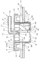
図7〜図9は、この発明の前提となる第3の実施の形態に係る燃料タンク用コネクタAを示したものであって、図7では、この実施の形態に係る燃料タンク用コネクタAを燃料タンクBに備え付ける前の状態を、当該燃料タンクBの一部と共に縦断面して示しており、図8では、この燃料タンク用コネクタAを燃料タンクBに備え付けるために当該燃料タンクBの面に燃料タンク用コネクタAを添装した状態を上方から見て示している。
また、図9では、この燃料タンク用コネクタAを燃料タンクBに備え付けた状態を、当該燃料タンクBの一部と共に縦断面して示している。
【0024】
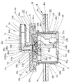
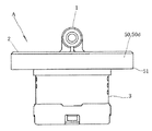
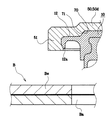
図10〜図16ならびに図19および図20は、この発明を適用して構成された第4の実施の形態に係る燃料タンク用コネクタAを示したものであって、図10ないし図12では、かかる燃料タンク用コネクタAを異なる向きから見てそれぞれ示しており、また、図13では、かかる燃料タンク用コネクタAを燃料タンクBに備え付ける前の状態を、当該燃料タンクBの一部と共に縦断面して示しており、図14では、この燃料タンク用コネクタAを燃料タンクBに備え付けた状態を、当該燃料タンクBの一部と共に縦断面して示している。また、図15では、このように燃料タンクBに備え付けられる燃料タンク用コネクタAの当該燃料タンクBに溶着される部分を拡大した状態で、また、図16では、当該燃料タンクBに溶着されたかかる部分を拡大した状態で、それぞれ示している。また、図19では、図10ないし図16に示される構成例と燃料タンクBに溶着される部分の構成を一部異ならせた構成例を理解しやすいように、かかる構成例における燃料タンクBに溶着される部分を拡大した状態で、また、図20では、当該燃料タンクBに溶着されたかかる部分を拡大した状態で、示している。
なお、図17および図18ならびに図21および図22に示される例は、この発明に係るものではなく、この発明と前提を共通にする燃料タンク用コネクタAを示したものであって、図17、図21では、図10ないし図16に示される構成例と燃料タンクBに溶着される部分の構成を一部異ならせた構成例を理解しやすいように、かかる構成例における燃料タンクBに溶着される部分を拡大した状態で、また、図18、図22では、当該燃料タンクBに溶着されたかかる部分を拡大した状態で、それぞれ示している。(図18は図17の構成例を燃料タンクBに溶着させた状態を、図22は図21の構成例を燃料タンクBに溶着させた状態を、それぞれ示している。)
【0025】
この典型的な実施の形態に係る燃料タンク用コネクタAは、燃料タンクBに開設された開口Baを外側から覆うように該開口Baの開口部Bcに備え付けられて該燃料タンクBと該燃料タンクBに接続される管Cとを連通状態に接続するコネクタAであって、該コネクタAが、筒状部11と、該筒状部11の外周側に備えられ且つ前記燃料タンクBの開口Baよりも大きい面を有する鍔状部12とを備えたガスバリヤ性合成樹脂製のガスバリヤ体10を備えて構成してあると共に、該ガスバリヤ体10が、ポリブチレンテレフタレート製、ポリフェニレンスルフィド製、リキッドクリスタルポリマ製、脂肪族ポリケトン製、芳香族ポリアミド製、エチレン−ビニルアルコール共重合体と高密度ポリエチレンとのブレンドポリマー製、ポリアミドとポリエチレンとのブレンドポリマー製、ポリアミドと高密度ポリエチレンとのブレンドポリマー製又はポリエチレンテレフタレート製である構成としてあり、前記燃料タンクB内にもたらされる燃料からの蒸発ガスが、当該コネクタA部分から漏れ出すのを効果的に減じるようにしてある。
【0026】
かかる燃料タンク用コネクタAは、典型的には、耐燃料油性などの当該燃料タンク用コネクタAに要請される各種の特性を備えたものとして構成され、前記燃料タンクBに備えられている各種の開口Baの開口部Bcに備えられて、この燃料タンクBに接続備えられる各種の管C、例えば、各種の通気管や、燃料供給管などの当該燃料タンクBに対する接続に用いられる。
【0027】
また、かかる燃料タンク用コネクタAは、このコネクタAに各種の弁機構、例えば、フューエルカットオフバルブ3などを備え、又は、これらの弁機構を備えない状態で、前記燃料タンクBに各種の管Cを接続するのに用いられる。
【0028】
また、かかる燃料タンク用コネクタAを構成するガスバリヤ体10は、当該コネクタAの構成に適し、且つ、燃料から生じて前記燃料タンクB内にもたらされる各種の燃料から生ずるガスの透過し難い素材であるポリブチレンテレフタレート、ポリフェニレンスルフィド、リキッドクリスタルポリマ、脂肪族ポリケトン、芳香族ポリアミド、エチレン−ビニルアルコール共重合体と高密度ポリエチレンとのブレンドポリマー、ポリアミドとポリエチレンとのブレンドポリマー製、ポリアミドと高密度ポリエチレンとのブレンドポリマー又はポリエチレンテレフタレートの、いずれかによって構成してあればよく、これによって、当該コネクタAに、典型的なガスバリヤ機能をもたらすことができる。
【0029】
なお、上記ガスバリヤ体10を構成するガスバリヤ性合成樹脂は、いずれも燃料から生ずる各種ガスの透過し難いものであって、その典型的なガスバリヤ性合成樹脂を高密度ポリエチレンと対比して、以下の燃料透過性試験を同一の条件で行ったところ、該高密度ポリエチレンの燃料透過量に対して、前記典型的なガスバリヤ性合成樹脂の燃料透過量は、いずれも著しく少なく、かかる高密度ポリエチレンに対しこれら典型的なガスバリヤ性合成樹脂はいずれも優れたガスバリヤ性を有することが認められた。
【0030】
[燃料透過性試験」
前記典型的な各ガスバリヤ性合成樹脂製試料と前記高密度ポリエチレン製試料とを夫々各別に測定対象合成樹脂製試料として用意すると共に、この各測定対象合成樹脂製試料に夫々対応する直径38mmのアルミカップを用意し、
試験薬品として、
(1)無鉛レギュラーガソリン(JIS K2202 2号相当品)…試薬1と、
(2)無鉛レギュラーガソリン(JIS K2202 2号相当品)90vol%とエタノール10vol%との混合燃料…試薬2とを用意し、
4.6gの前記試薬1を入れた前記アルミカップと、4.6gの前記試薬2を入れた前記アルミカップとを任意複数個用意すると共に、一個のアルミカップの開口を前記用意された測定対象合成樹脂製試料の一つで密閉するように、前記夫々のアルミカップ上に前記各測定対象合成樹脂製試料を個別に載置固定し、60℃の試験温度において48時間経過後における減少重量測定によって、11.341cm2 の透過面積の48時間の燃料透過量を気相法で測定した燃料透過性試験(JIS Z 0208−76に準じた燃料透過性試験)において表1の通りであった。
【0031】
【表1】

また、このガスバリヤ体10は、筒状部11と、該筒状部11の外周側に備えられ且つ前記開口Baよりも大きい面を有する鍔状部12とを備えて構成されており、更に、必要に応じて、当該燃料タンク用コネクタAに必要とされる他の任意の構成を備えたものとして構成される。
【0033】
すなわち、前記コネクタAは、かかるガスバリヤ体10を構成する筒状部11及び鍔状部12を一部に含んで構成される筒状部1及び鍔状部2を備えた構成としてある。また、かかる筒状部1及び鍔状部2にフューエルカットオフバルブ3などの他の構成部分を備え付けて当該コネクタAを構成するようにしてあってもよい。
【0034】
また、かかる燃料タンク用コネクタAの備え付けられる燃料タンクBは、いかなる構成の燃料タンクBであってもよく、例えば、全体が合成樹脂製の燃料タンクBや、前記開口周縁Bb側方の外面部を前記コネクタAに溶着可能な合成樹脂製として、他の部分を他の合成樹脂や、金属や、更に他の適宜の素材によって構成した燃料タンクBとしてあってもよい。
【0035】
また、かかる構成からなる燃料タンク用コネクタAは、前記ガスバリヤ体10における鍔状部12の外周部を、前記燃料タンクBのガスバリヤ性合成樹脂Bdに溶着して、該燃料タンクBに備え付けられる構成とすることによって、前記特長に併せて、燃料タンクからの燃料蒸発ガスの漏れ出しを、より効果的に減少させることができる。
【0036】
また、かかる構成からなる燃料タンク用コネクタAは、前記ガスバリヤ体10の表面の少なくとも一部、典型的には、前記筒状部11内を除く該ガスバリヤ体10の表面の少なくとも一部が接着性オレフィン樹脂製の外殻体部50aで覆われる構成とすることによって、前記特長に併せて、一体に外殻体部50aを備えられたガスバリヤ体10を、当該外殻体部50において燃料タンクBに対して、確実且つ容易に溶着して備え付けることができる。
【0037】
また、かかる構成からなる燃料タンク用コネクタAは、前記ガスバリヤ体10の表面の少なくとも一部を覆う接着性オレフィン樹脂製の外殻体部50aの表面の少なくとも一部と該外殻体部50aで覆われていない前記ガスバリヤ体10の表面の少なくとも一部が高密度ポリエチレン製の外殻体部50bで覆われた構成とすることによって、前記特長に併せて、前記ガスバリヤ体10に対して高密度ポリエチレン製の外殻体部50bを、より容易且つ確実に備えることができ、当該コネクタAを、より確実且つ容易に、燃料タンクBに溶着して備え付けることができる。
【0038】
また、かかる構成からなる燃料タンク用コネクタAは、前記鍔状部12の先端側に、前記燃料タンクBの外面部に向けて突き出す環状突出し部12aが備えられた構成とすることによって、前記特長に併せて、前記蒸発ガスの、当該燃料タンクBからの漏れ出しを効果的に減少させた状態での、当該コネクタAの燃料タンクBに対する取付けにおける設計の自由度を増すことができる。
【0039】
また、かかる構成からなる燃料タンク用コネクタAは、該コネクタAを、燃料供給管の接続用コネクタとすることによって、前記特長に併せて、燃料から生ずる蒸発ガスの漏洩を効果的に減じた状態で、燃料供給管を燃料タンクBに接続することができる。
【0040】
また、かかる構成からなる燃料タンク用コネクタAは、該コネクタAを、通気管の接続用コネクタとすることによって、前記特長に併せて、燃料から生ずる蒸発ガスの漏洩を効果的に減じた状態で、通気管を燃料タンクBに接続することができる。
【0041】
また、かかる構成からなる燃料タンク用コネクタAは、該コネクタAをフューエルカットオフバルブ3を備えた構成とすることによって、前記特長に併せて、燃料から生ずる蒸発ガスの漏洩を効果的に減じた状態で、管Cと燃料タンクBとをフューエルカットオフバルブ3を介して接続することができる。
【0042】
(1) 第1の実施の形態に係る燃料タンク用コネクタA
先ず、図1〜図3で示される第1の実施の形態に係る燃料タンク用コネクタAについて具体的に説明する。
この図示例に係る燃料タンク用コネクタAは、燃料タンクBに各種の管Cを接続する手段として構成されており、特に、典型的なフューエルカットオフバルブ3を備えた燃料タンク用コネクタAとして示されている。
【0043】
この図示例に係る燃料タンク用コネクタAは、燃料タンクBに開設された開口Baを外側から覆うように該開口Baの開口部Bcに備え付けられて該燃料タンクBと該燃料タンクBに接続される管Cとを連通状態に接続するコネクタAであって、該コネクタAが、筒状部11と、該筒状部11の外周側に備えられ且つ前記燃料タンクBの開口Baよりも大きい面を有する鍔状部12とを備えたガスバリヤ性合成樹脂製のガスバリヤ体10を備えて構成してあると共に、該ガスバリヤ体10が、ポリブチレンテレフタレート製、ポリフェニレンスルフィド製、リキッドクリスタルポリマ製、脂肪族ポリケトン製、芳香族ポリアミド製、エチレン−ビニルアルコール共重合体と高密度ポリエチレンとのブレンドポリマー製、ポリアミドとポリエチレンとのブレンドポリマー製、ポリアミドと高密度ポリエチレンとのブレンドポリマー製又はポリエチレンテレフタレート製である構成としてあり、この図示例にあっては、前記ガスバリヤ体10の表面の少なくとも一部が外殻体部50によって覆われた構成、より具体的には、該ガスバリヤ体10の表面の少なくとも一部が接着性オレフィン樹脂製の外殻体部50aで覆われていると共に、この外殻体部50aの少なくとも一部と、この外殻体部50aで覆われていない該ガスバリヤ体10の表面の少なくとも一部が高密度ポリエチレン製の外殻体部50bによって覆われた構成としてあり、この外殻体部50で前記燃料タンクBに溶着されて前記燃料タンクB内にもたらされる燃料からの蒸発ガスが、当該コネクタA部分から漏れ出すのを効果的に減じるようにしてある。
【0044】
この図示例に係るコネクタAは、かかる燃料タンクBに各種の管Cを連結する手段として用いられるものであって、この図示例にあっては、その典型例として、典型的なフューエルカットオフバルブ3を備えて燃料タンクBの上部側に備え付けられるコネクタAを示しており、燃料から蒸発されるガスなどをキャニスタなどに移送案内すると共に、燃料タンクB内にある燃料液面の変動に際して、当該燃料の流出を防止するようにしてある。
【0045】
この図示例に係るコネクタAの備えられる燃料タンクBは、少なくとも当該コネクタAにおける外殻体部50の溶着されるタンク部分、即ち、当該燃料タンクBにおける少なくとも開口周縁Bb側方の外面部を、この外殻体部50に溶着可能な合成樹脂製とされた構成としてあり、しかも、ガスバリヤ層、即ち、前記燃料からの蒸発ガスの透過し難い層を備えたものとして構成してある。
【0046】
この燃料タンクBは、典型的には、該燃料タンクBを、前記コネクタAの溶着に都合の良い合成樹脂、例えば、高密度ポリエチレンなどによって、当該燃料タンクBの表面側層Beを構成してあると共に、燃料からの蒸発ガスの透過し難いガスバリヤ性合成樹脂Bdの層を備えた構成としてあり、この図示例にあっては、このガスバリヤ性合成樹脂Bdが表面に露出するように、前記開口周縁Bbに沿った部分に周回凹段部Bfを構成するように前記表面側層Beを取り除いた構成としてある。
【0047】
この図示例に係るコネクタAは、孔1eを備えた筒状部1と、該筒状部1の外周側に備えられ、且つ、前記開口Baよりも大きい面を有する鍔状部2と、フューエルカットオフバルブ3とを備えた構成としてあり、燃料タンクBの開口Baから、燃料タンクB内に前記フューエルカットオフバルブ3における筒状体20を構成する筒部23側を差し入れた状態で、前記鍔状部2を、少なくとも開口周縁Bb側方を合成樹脂製とした燃料タンクBにおける当該合成樹脂製の燃料タンクBの面部に溶着して、該燃料タンクBと該燃料タンクBに接続される管Cとを前記孔1eで連通状態に接続させるコネクタAとしてある。
なお、この図示例に係る開口Baは円形の開口Baとしてあると共に、前記鍔状部2が円板状の構成としてあり、この鍔状部2が前記開口Baの直径よりも大きい直径に構成してある。
【0048】
この図示例に係るコネクタAは、更に、具体的には、一旦上方に向けて突き出すように備えられた縦向き筒状部1aと、この縦向き筒状部1aの上部側に、該縦向き筒状部1aから直角に屈曲して連接されている横向き筒状部1bとを備えた筒状部1と、この筒状部1における前記縦向き筒状部1aの下部側の外周側から側方に張り出すように備えられた円板状をなす鍔状部2とを有すると共に、これにフューエルカットオフバルブ3を備えた構成、即ち、この鍔状部2の下面側、即ち、前記筒状部1の備えられている側と反対の側に、該鍔状部2から隆起するように備えられている盤状部21と、この盤状部21の周縁部から下方に向けて突き出すように備えられている円筒状の筒部23と、この筒部23の下端縁に備えられている掛止突部23bを掛止孔24cに掛止して備え付けられる蓋体24と、前記盤状部21における前記筒状部1の孔1eに連続して備えられている凹部22内に備え付けられる弁座体30と、この弁座30bを有する弁座体30を備えた盤状部21及び筒部23並びに蓋体24によって構成されるフロート室内に、このフロート室内に流入する液体の液面レベルの変化に対応して上下方向に移動自在に納め入れられるフロート40とを有し、このフロート40の上部側に備えられている弁体部40aを、該フロート40の燃料液面の変動に伴う弁座30bに向けた移動に伴って、前記弁座体30における弁座30bに密着して、前記筒状部1の孔1eを塞ぎ状態とする構成としてある。
【0049】
かかるコネクタAに備えられるガスバリヤ体10は、燃料タンクB内にもたらされるガス、典型的には、燃料から蒸発されるガスの透過を極力阻止する機能を備えたガスバリヤ性合成樹脂としての、ポリブチレンテレフタレート製、ポリフェニレンスルフィド製、リキッドクリスタルポリマ製、脂肪族ポリケトン製、芳香族ポリアミド製、エチレン−ビニルアルコール共重合体と高密度ポリエチレンとのブレンドポリマー製、ポリアミドとポリエチレンとのブレンドポリマー製、ポリアミドと高密度ポリエチレンとのブレンドポリマー製又はポリエチレンテレフタレート製としてあり、この図示例にあっては、前記孔1eを構成する孔11eを備えた筒状部11と、この筒状部11の一端側の外周部から側方に張出すように備えられている鍔状部12とを備えた構成としてある。
【0050】
前記筒状部11は、エルボ状をなすように縦向き筒状部11bと該縦向き筒状部11bに直角に連続されている横向き筒状部11aとを備えた構成としてあり、この縦向き筒状部11bの下端側の外周部から側方に突き出すように前記鍔状部12が一体に備えられた構成としてある。
【0051】
かかる縦向き筒状部11bの外周部に備えられる鍔状部12は、前記燃料タンクBにおける開口Baよりも大きい面を備えた構成、即ち、この筒状部11に備えられる鍔状部12を、この筒状部11の外周部から、前記燃料タンクBにおける開口周縁Bbの側方部に向けて延びるように備えられた構成としてあり、更に、具体的には、該鍔状部12が円形板状としてあり、この鍔状部12が前記円形状に構成されている開口Baの直径よりも大きい直径を備えたものとして構成してある。
【0052】
かかる構成の鍔状部12における前記燃料タンクBの外面に向き合う側、即ち、前記筒状部11の突き出し側と反対の側にある該鍔状部12の外周縁部から下方、即ち、燃料タンクBの側に向けて屈曲状に、環状突き出し部12aを突き出し状に備えた構成としてある。
【0053】
かかる構成からなるガスバリヤ体10における下面側、即ち、前記筒状部11の突き出し側と反対の側に、前記フューエルカットオフバルブ3が一体に備えられた構成としてある。
【0054】
このフューエルカットオフバルブ3は、上部側に盤状部21を一体に備えて前記ガスバリヤ体10と一体に構成されている筒状体20と、この筒状体20における該盤状部21に一体に備えられている弁座体30と、この筒状体20における下面開口の筒部23の下端側に備え付けられて該開口を塞ぐ蓋体24と、この蓋体24によって塞がれる筒状体20内に構成されるフロート室内に納め入れられて、燃料液面の変動に追随して、前記弁座体30における弁座30bの開閉をなすフロート40とを備えた構成としてある。
【0055】
このフューエルカットオフバルブ3を構成する筒状体20は、盤状部21と、この盤状部21から一体に突き出し状態に備えられている筒部23とを備えた構成としてあり、各種の合成樹脂、典型的には、ガスバリヤ性合成樹脂、例えば、ポリアセタールなどによって構成してある。
【0056】
この筒状体20を構成する盤状部21は、その厚さ内に、外部に連通して、成形樹脂の流入される空洞部21aを有していると共に、その外周縁部から下方に向けて該盤状部21に一体に、前記筒部23を備えた構成としてあり、また、盤状部21のほぼ中央部には、前記筒状部11の孔11eに連通して、該筒状部11の開口部11cを構成する凹部22を備えた構成としてある。
【0057】
この盤状部21に備えられる凹部22は、前記筒状部11の孔11eに連通するように備えられており、この孔11eよりも大きい孔径のものとして構成してあり、この図示例にあっては、前記盤状部21の下部側に、上方に凹むように備えられている拡径凹段状孔部22aと、この拡径凹段状孔部22aの上部側から前記筒状部11側に向けて備えられる円錐状孔部22bと、この円錐状孔部22bから、該筒状部11の側に至るように備えられた凹段状孔部22cとして構成してある。
【0058】
また、前記筒部23は、前記盤状部21から一体に突設状態に備えられている下面開口の筒体として構成してあると共に、その下端縁である先端側の外側部に、蓋体24の組み付け用の掛止突部23bを設けてあり、しかも、その外周壁部に、複数の孔23aを備えた構成としてあると共に、該筒部23の内壁の先端側から前記盤状部21の側に向けて備えられる複数のガイドリブ23cを有する構成としてある。
【0059】
この筒部23に備えられる孔23aは、フロート40を納め入れ、且つ、蓋体24で塞がれる当該筒部23内と燃料タンクB内との間におけるガスなどの移動を円滑になし得る構成を備えたものとしてある。
【0060】
かかる構成からなる筒状体20と、前記ガスバリヤ体10は、例えば、この筒状体20を、成形金型内にインサートすると共に、この成形金型内に該ガスバリヤ体10の成形用合成樹脂を射出などによって注入し、当該筒状体20における前記空洞部21aに対する当該成形用合成樹脂の充填と共に、この筒状体20における盤状部21の周側部と、この盤状部21における前記筒部23の突設側と反対側にある面とを当該成形合成樹脂によって覆うように、当該ガスバリヤ体10を成形することによって、この筒状体20と前記ガスバリヤ体10とを一体に構成してある。
【0061】
即ち、この図示例にあっては、前記ガスバリヤ体10を、該盤状部21における前記筒部23の突設側と反対側にある面を覆うと共に該面から更に側方に突き出すように備えられている鍔状部12と、この鍔状部12の下面側から該盤状部21の周側面を覆うように突き出し状態に備えられている覆い部12bと、該盤状部21における凹段状孔部22cに連通する孔11eを備えるように、前記鍔状部12の上面から上方に突き出すように備えられている筒状部11と、前記鍔状部12の先端側から下方に向けて屈曲状に備えられている環状突き出し部12aとを備えるように、前記筒状体20に一体に設けてある。
【0062】
このように筒状体20に一体に備えられるガスバリヤ体10は、その表面、この図示例にあっては、前記覆い部12bの表面部と、この表面部から前記環状突き出し部12aの先端を経て前記筒状部11の開口端11dに到る当該ガスバリヤ体10における表面を外殻体部50によって覆った構成としてある。
かかるガスバリヤ体10に備えられる外殻体部50は、例えば、前記筒状体20に該ガスバリヤ体10を一体に備えると共に、これを成形金型内にインサートしてなされるプラスチック成形によって当該ガスバリヤ体10の表面部に設けることができる。
【0063】
このようにガスバリヤ体10の表面を覆うように備えられる外殻体部50は、このガスバリヤ体10に一体に成形可能であり、しかも、前記燃料タンクBに溶着可能な合成樹脂によって構成してあり、この図示例にあっては、前記覆い部12bの表面部と、この表面部から前記環状突き出し部12aの先端を経て前記縦向き筒状部11bの途中まで到る当該ガスバリヤ体10の表面を覆う接着性オレフィン樹脂製外殻体部50aと、前記環状突き出し部12aを覆っている該接着性オレフィン樹脂製外殻体部50aにおける前記燃料タンクBに面した面に連続されている外周面と、この外周面から前記筒状部11の開口端11dに到る面、即ち、当該間にあって、前記接着性オレフィン樹脂製外殻体部50a及びガスバリヤ体10により構成されている表面とを覆う高密度ポリエチレン製外殻体部50bとを一体に積層状態に備えた構成としてある。
【0064】
即ち、この図示例にあっては、前記ガスバリヤ体10における鍔状部12及び筒状部12に、前記外殻体部50を一体に備えた状態で、当該コネクタAにおける鍔状部2及び筒状部1を構成してあり、この鍔状部2の先端部に、前記環状突き出し部12a及び該環状突き出し部12aを覆う外殻体部50によって構成される環状突き出し部2aを備えた構成としてある。
【0065】
次いで、前記筒状体20における盤状部21の凹部22に備え付けられて、前記フューエルカットオフバルブ3の弁座30bを構成する弁座体30は、該盤状部21に対する溶着に適し、しかも、この盤状部21と共にガスバリヤ機能を当該コネクタAにもたらす合成樹脂、即ち、燃料から蒸発されるガスの透過を効果的に防止する各種ガスバリヤ性合成樹脂、例えば、ポリアセタールなどによって構成してあり、前記フロート40における弁体部40aを受け入れ塞がれる弁座30bを、上下方向に貫通して備えられている孔30aの孔縁部に備えていると共に前記凹部22に組み入れられる形状を備えた構成としてある。
【0066】
即ち、この弁座体30は、ほぼ中心部に前記孔1e、11eに連通する上下方向に貫通する孔30aを備えていると共に、この孔30aの中央部を縮径孔部30a’とし、この縮径孔部30a’から下方を漸次該孔30aの下端縁に向けて拡径とする円錐孔状の弁座30bとして構成してあり、また、この弁座体30の上部側に前記孔30aを取り巻くように環状凹溝30cが設けてあり、この環状凹溝30cによって該弁座体30の上部側の中央部に筒状部30dを形成してあると共に、この筒状部30dを構成する環状凹溝30cの外方を上部側円盤状部30eとし、また、この上部側円盤状部30eよりも下方側を、この上部側円盤状部30eよりも大きい直径の下部側円盤状部30fとして構成してあり、且つ、前記上部側円盤状部30eの外周面に環状シール材31を嵌め付けた状態で、この上部側円盤状部30eの上端側を前記円錐状孔部22bに押し当て、且つ、該下部側円盤状部30fの上端面を前記拡径凹段状孔部22aにおける上端面に密着するように、該下部側円盤状部30fを前記最下段にある拡径凹段状孔部22aに納め入れた状態で、この弁座体30を前記盤状部21に溶着、一体に備え付けてある。
【0067】
かかる構成からなる筒状体20内に組み入れられるフロート40は、例えば、ポリアセタールなどによって構成してあり、筒部23内で、前記ガイドリブ23cに案内されて燃料液面の変動に伴って円滑に上下方向に移動し得るように備えられており、燃料液面の変動に伴う該弁座30bに向けた移動に際して、前記弁座30bに密着して該弁座体30の孔30aを塞ぐ弁体部40aを、その上端部側に備えた構成としてあり、その下部側のほぼ中央部に上方に凹む凹部40bを有し、しかも、この凹部40b内に、更に上方に凹む環状凹部40b’を有し、該凹部40b内に円形台状部40cを備えた構成としてあると共に、この凹部40bと該フロート40の上端面とを連通する孔40dを備えた構成としてある。
【0068】
次いで、このフューエルカットオフバルブ3を構成するフロート40を前記筒部23内に組入れ状態に維持する蓋体24は、円板状をなす底板部24aの周縁部から上方に起立する筒状周壁部24bを有し、この筒状周壁部24b内に前記筒部23を、該筒部23の先端を該底板部24aに当接させるように受け入れると共に、この筒部23に備えられている掛止突部23bを該筒状周壁部24bに備えられている掛止孔24cの孔縁に掛止して、該筒部23に組み付けられた構成としてあり、この蓋体24の内側のほぼ中央部に備えられている円形台状部24dと前記フロート40における円形台状部40cに嵌め付けた圧縮コイルバネ41によって、該フロート40を該筒部23内において容易に燃料液面の変動に追随して浮き上り移動し得るように組み付けてある。
【0069】
かかる筒部23内にフロート40を組み付ける蓋体24は、その底板部24aに上下に貫通する複数の孔24eを設けてあり、この筒部23内に対して燃料やガスなどが容易に流出入し得る構成としてある。
【0070】
なお、前記圧縮コイルバネ41は、前記フロート40が燃料液によって浮力を浮けていない状態で、該フロート40の重量とバランスを保って、このフロート40が、前記弁体部40aを前記弁座30bから離れた位置に維持されるように弾持し、このフロート40が燃料液による浮力を受けた際に、この浮力によって該フロート40が容易に浮き上がり移動し得ると共に、車両の転倒などに際して、該フロート40を、その浮力に抗して、該フロート40における弁体部40aを前記弁座30bに押しつけ得るように構成してある。
【0071】
かかる構成からなる前記外殻体部50とガスバリヤ体10とを備えて構成される筒状部1と鍔状部2とを有すると共にフューエルカットオフバルブ3を備えて構成されるコネクタAは、このフューエルカットオフバルブ3を構成する盤状部21に前記弁座体30を一体に溶着、備え付けると共に、前記筒部23内にフロート40を納め入れ、且つ、この納め入れフロート40との間に前記圧縮コイルバネ41を介装した状態で、この筒部23の下部開口に蓋体24を組み付けて構成してある。
【0072】
このように構成されたコネクタAは、この図示例にあっては、前記筒部23側を、前記燃料タンクBの上部側に備えられている開口Baから該燃料タンクB内に差し入れると共に、前記燃料タンクBに備えられている周回凹段部Bfに露出されている前記ガスバリヤ性合成樹脂Bdに、該コネクタAにおける前記ガスバリヤ体10の環状突き出し部12aが溶着され、且つ、燃料タンクBに、前記環状突き出し部2aが溶着されるように、この周回凹段部Bfに該環状突き出し部2aを納め入れると共に、前記環状突き出し部12aを前記ガスバリヤ性合成樹脂Bdに溶着し、且つ、該環状突き出し部2aにおける外殻体部50を燃料タンクBに溶着して備え付けられる。
【0073】
かかるコネクタAの燃料タンクBの開口部Bcに対する取り付けによって、前記燃料からの蒸発ガスの当該燃料タンクBからの漏れ出しを前記ガスバリヤ体10によって効果的に減ずることができる。
【0074】
また、前記コネクタAの燃料タンクBに対する取り付けを、当該コネクタAの燃料タンクBに対する溶着とすることによって、このコネクタAを容易且つ確実に燃料タンクBに備え付けることができる。
また、かかる溶着による当該コネクタAの燃料タンクBに対する取り付けにおいて、該コネクタAにおけるガスバリヤ体10を該燃料タンクBにおけるガスバリヤ性合成樹脂Bdに溶着することによって、前記ガスの当該燃料タンクBからの漏れ出しを、更に、効果的に減少させることができる。
【0075】
このように燃料タンクBに備え付けられたコネクタAに、適宜管Cを接続して用いる。
この管Cの接続される当該コネクタAにおける筒状部1は、この接続される管Cが容易且つ確実に接続状態を維持され得るように、この図示例にあっては、この筒状部1における横向き筒状部1bの外周面に、先窄まりの円錐状案内部1cと、この円錐状案内部1cの頂端から該横向き筒状部1bに到る垂直な段差状面1dを備えた隆起部を複数備えた構成としてある。
【0076】
(2) 第2の実施の形態に係る燃料タンク用コネクタA
次いで、図4〜図6で示される第2の実施の形態に係る燃料タンク用コネクタAについて具体的に説明する。
この図示例に係る燃料タンク用コネクタAは、燃料タンクBに各種の管Cを接続する手段として構成されており、特に、典型的なフューエルカットオフバルブ3を備えて、燃料タンクBの上部側に備えられるコネクタAとして示されている。
【0077】
この図示例に係る燃料タンク用コネクタAは、燃料タンクBに開設された開口Baを外側から覆うように該開口Baの開口部Bcに備え付けられて該燃料タンクBと該燃料タンクBに接続される管Cとを連通状態に接続するコネクタAであって、該コネクタAが、筒状部11と、該筒状部11の外周側に備えられ且つ前記燃料タンクBの開口Baよりも大きい面を有する鍔状部12とを備えたガスバリヤ性合成樹脂製のガスバリヤ体10を備えて構成してあると共に、該ガスバリヤ体10が、ポリブチレンテレフタレート製、ポリフェニレンスルフィド製、リキッドクリスタルポリマ製、脂肪族ポリケトン製、芳香族ポリアミド製、エチレン−ビニルアルコール共重合体と高密度ポリエチレンとのブレンドポリマー製、ポリアミドとポリエチレンとのブレンドポリマー製、ポリアミドと高密度ポリエチレンとのブレンドポリマー製又はポリエチレンテレフタレート製である構成としてあり、この図示例にあっては、前記ガスバリヤ体10の表面の少なくとも一部を外殻体部50によって覆われた構成、より具体的には、該ガスバリヤ体10の表面を接着性オレフィン樹脂製の外殻体部50aで覆われた構成としてあり、この外殻体部50で前記燃料タンクBに溶着されて前記燃料タンクB内にもたらされる燃料からの蒸発ガスが、当該コネクタA部分から漏れ出すのを効果的に減じるようにしてある。
【0078】
この第2の実施の形態に係る燃料タンク用コネクタAは、当該コネクタAに備えられる外殻体部50を、接着性オレフィン樹脂の単一層として、この燃料タンク用コネクタAを構成するガスバリヤ体10に設けた以外の構成を、前記第1の実施の形態に係る燃料タンク用コネクタAの構成と同一又は実質的に同一の構成としてあり、同一の方法で燃料タンクBに備えつけ用いることができる。
従って、前記第1の実施の形態に係る燃料タンク用コネクタAの構成と同一又は実質的に同一の構成部分には、同一の番号を付して、その説明を省略する。
【0079】
この第2の実施の形態に係る燃料タンク用コネクタAにおいて、前記ガスバリヤ体10に備えられる外殻体部50は、前記第1の実施の形態に係る燃料タンク用コネクタAにおけると同様に、例えば、前記筒状体20に該ガスバリヤ体10を一体に備えると共に、これを成形金型内にインサートしてなされるプラスチック成形によって当該ガスバリヤ体10の表面部に設けることができる。
【0080】
このようにガスバリヤ体10の表面を覆うように備えられる外殻体部50は、このガスバリヤ体10に一体に成形可能であり、しかも、前記燃料タンクBに溶着可能な合成樹脂によって構成してあり、この図示例にあっては、前記覆い部12bの表面部と、この表面部から前記環状突き出し部12aの先端を経て前記筒状部11の開口端11dに到る当該ガスバリヤ体10の表面を、該ガスバリヤ体10と一体になるように覆う接着性オレフィン樹脂製外殻体部50aによって構成してある。
【0081】
このように構成されたコネクタAは、この図示例にあっては、前記筒部23側を、前記燃料タンクBの上部側に備えられている開口Baから該燃料タンクB内に差し入れると共に、前記燃料タンクBに備えられている周回凹段部Bfに露出されている前記ガスバリヤ性合成樹脂Bdに、該コネクタAにおける前記ガスバリヤ体10の環状突き出し部12aが溶着され、且つ、燃料タンクBに、前記環状突き出し部2aが溶着されるように、この周回凹段部Bfに該環状突き出し部2aを納め入れると共に、前記環状突き出し部12aを前記ガスバリヤ性合成樹脂Bdに溶着し、且つ、該環状突き出し部2aにおける外殻体部50を燃料タンクBに溶着して備え付けられる。
【0082】
かかるコネクタAの燃料タンクBの開口部Bcに対する取り付けによって、前記燃料からの蒸発ガスの当該燃料タンクBからの漏れ出しを前記ガスバリヤ体10によって効果的に減ずることができる。
また、前記コネクタAの燃料タンクBに対する取り付けを、当該コネクタAの燃料タンクBに対する溶着とすることによって、このコネクタAを容易且つ確実に燃料タンクBに備え付けることができる。
また、かかる溶着による当該コネクタAの燃料タンクBに対する取り付けにおいて、該コネクタAにおけるガスバリヤ体10を該燃料タンクBにおけるガスバリヤ性合成樹脂Bdに溶着することによって、前記ガスの当該燃料タンクBからの漏れ出しを、更に、効果的に減少させることができる。
【0083】
(3) 第3の実施の形態に係る燃料タンク用コネクタA
次いで、図7〜図9で示される第3の実施の形態に係る燃料タンク用コネクタAについて具体的に説明する。
この図示例に係る燃料タンク用コネクタAは、燃料タンクBに各種の管Cを接続する手段として構成されており、特に、典型的なフューエルカットオフバルブ3を備えた燃料タンク用コネクタAとして示されている。
【0084】
この図示例に係る燃料タンク用コネクタAは、燃料タンクBに開設された開口Baを外側から覆うように該開口Baの開口部Bcに備え付けられて該燃料タンクBと該燃料タンクBに接続される管Cとを連通状態に接続するコネクタAであって、該コネクタAが、筒状部11と、該筒状部11の外周側に備えられ且つ前記燃料タンクBの開口Baよりも大きい面を有する鍔状部12とを備えたガスバリヤ性合成樹脂製のガスバリヤ体10を備えて構成してあると共に、該ガスバリヤ体10が、ポリブチレンテレフタレート製、ポリフェニレンスルフィド製、リキッドクリスタルポリマ製、脂肪族ポリケトン製、芳香族ポリアミド製、エチレン−ビニルアルコール共重合体と高密度ポリエチレンとのブレンドポリマー製、ポリアミドとポリエチレンとのブレンドポリマー製、ポリアミドと高密度ポリエチレンとのブレンドポリマー製又はポリエチレンテレフタレート製である構成としてあり、この図示例にあっては、前記ガスバリヤ体10の表面の少なくとも一部が外殻体部50によって覆われた構成、より具体的には、このガスバリヤ体10における燃料タンクBに向き合う側に接着性のある変性ポリオレフィン樹脂製の外殻体部50cを一体に備えた構成としてあり、この外殻体部50cにおいて燃料タンクBに溶着で備え付けられて、前記燃料タンクB内にもたらされる燃料からの蒸発ガスが、当該コネクタA部分から漏れ出すのを効果的に減じるようにしてある。
【0085】
この図示例に係るコネクタAは、かかる燃料タンクBに各種の管Cを連結する手段として用いられるものであって、この図示例にあっては、その典型例として、典型的なフューエルカットオフバルブ3を備えて燃料タンクBの上部側に備え付けられるコネクタAを示しており、燃料から蒸発されるガスなどをキャニスタなどに移送案内すると共に、燃料タンクB内にある燃料液面の変動に際して、当該燃料の流出を防止するようにしてある。
【0086】
この図示例に係るコネクタAの備えられる燃料タンクBは、少なくとも当該コネクタAの溶着されるタンク部分、即ち、当該燃料タンクBにおける少なくとも開口周縁Bb側方を、このコネクタAに溶着可能な合成樹脂製とされた構成としてあり、しかも、ガスバリヤ層、即ち、前記燃料からの蒸発ガスの透過し難い層を備えたものとして構成してある。
【0087】
この燃料タンクBは、典型的には、該燃料タンクBを、前記コネクタAの溶着に都合の良い合成樹脂、例えば、ポリエチレンや高密度ポリエチレンなどによって、当該燃料タンクBの表面側層Beを構成してあると共に、燃料からの蒸発ガスの透過し難いガスバリヤ性合成樹脂Bdの層を備えた構成としてあり、この図示例にあっては、このガスバリヤ性合成樹脂Bdが表面に露出するように、前記開口周縁Bbに沿った部分に周回凹段部Bfを構成するように前記表面側層Beを取り除いた構成としてある。
【0088】
かかる燃料タンクBに備え付けられるコネクタAを構成するガスバリヤ体10は、この図示例にあっては、筒状部11と、該筒状部11の外周側に備えられ且つ前記燃料タンクBの開口Baよりも大きい面を有する鍔状部12とを備え、且つ、フューエルカットオフバルブ3を構成する比較的大きい径の筒部23を備えた構成としてあると共に、このガスバリヤ体10を、ポリブチレンテレフタレート製、ポリフェニレンスルフィド製、リキッドクリスタルポリマ製、脂肪族ポリケトン製、芳香族ポリアミド製、エチレン−ビニルアルコール共重合体と高密度ポリエチレンとのブレンドポリマー製、ポリアミドとポリエチレンとのブレンドポリマー製、ポリアミドと高密度ポリエチレンとのブレンドポリマー製又はポリエチレンテレフタレート製としてある。
【0089】
この図示例に係るガスバリヤ体10を構成する前記筒状部11は、前記鍔状部12から上方に突き出す縦向き筒状部11bと該縦向き筒状部11bに直角に連続されている横向き筒状部11aとを備え、且つ、前記鍔状部12から下方に向けて突き出すように突出筒状部11fを該縦向き筒状部11bに連通して備えた構成としてあり、この突出筒状部11fの下端部分に、該筒状部11の孔11eの下端部分に構成される凹部としての弁座11f’を備えた構成としてある。
【0090】
かかる縦向き筒状部11aの外周部に備えられる鍔状部12は、前記燃料タンクBにおける開口Baよりも大きい面を備えた構成、即ち、この筒状部11に備えられる鍔状部12を、この筒状部11の外周部から、前記燃料タンクBにおける開口周縁Bbの側方部に向けて延びるように備えられた構成としてあり、更に、具体的には、該鍔状部12が円形板状としてあり、この鍔状部12が前記円形状に構成されている開口Baの直径よりも大きい直径を備えたものとして構成してある。
【0091】
かかる構成の鍔状部12における前記燃料タンクBの外面に向き合う側、即ち、前記突出筒状部11fの突き出し側にある該鍔状部12の外周縁部から下方、即ち、燃料タンクBの側に向けて屈曲状に、環状突き出し部12a’を突き出し状に備えた構成としてある。
【0092】
かかる構成からなるガスバリヤ体10における下面側、即ち、前記突出筒状部11fの突き出し側に、前記フューエルカットオフバルブ3を構成する筒部23を一体に備えた構成としてある。
【0093】
このフューエルカットオフバルブ3を構成する筒部23は、前記鍔状部12の下面側から下方に向けて、前記突出筒状部11fを取り囲むように該鍔状部12に一体に突設状態に備えられている下面開口の筒体として構成してあると共に、その下端縁である先端側の外側部に、蓋体24の組み付け用の掛止突部23bを設けてあり、しかも、その外周壁部に、複数の孔23aを備えた構成としてあると共に、該筒部23の内壁の先端側から前記鍔状部12側に向けて備えられる複数のガイドリブ23cを有する構成としてある。
【0094】
この筒部23に備えられる孔23aは、フロート40を納め入れ、且つ、蓋体24で塞がれる当該筒部23内と燃料タンクB内との間におけるガスなどの移動を円滑になし得る構成を備えたものとしてある。
【0095】
このように構成されるガスバリヤ体10における前記筒部23の上部側の外周面と、これに続く前記鍔状部12の面と、この鍔状部12の面に続く前記環状突き出し部12a’の内側面とに、一連に連続するように外殻体部50を、該ガスバリヤ体10に一体に設け、この外殻体部50を利用して、当該コネクタAを前記燃料タンクBに溶着、備え付け得るようにしてある。
【0096】
この図示例に係る外殻体部50は、前記筒部23の上部外周に備えられる筒添装部53と、前記鍔状部12の下面側に備えられる鍔添装部52と、前記環状突き出し部12a’の内側に備えられると共に、この環状突き出し部12a’よりも、更に下方に突き出すように備えられる突き出し部54とを一体に備えた構成としてあり、この突き出し部54の先端部を、前記燃料タンクBにおける周回凹段部Bfに溶着した際に、前記環状突き出し部12a’の先端が、該燃料タンクBにおける外面に密着される構成としてある。
【0097】
かかるコネクタAを構成する外殻体部50は、各種の方法で当該ガスバリヤ体10に備えられる。例えば、当該ガスバリヤ体10を成形型内にインサートしてなされる当該成形型に対する合成樹脂の注入などによって、当該ガスバリヤ体10に一体に設けることができる。
【0098】
かかる外殻体部50は、更に典型的には、当該外殻対部50を接着性のある変性ポリオレフィン樹脂を用いた外殻体部50cとすることによって、例えば、前記ガスバリヤ体10をガスバリヤ性に優れたポリブチレンテレフタレート製とした場合にあっても、このポリブチレンテレフタレート製のガスバリヤ体10に当該外殻体部50cを確実に一体に備えることができ、しかも、前記燃料タンクB側の合成樹脂、例えば、ポリエチレンや高密度ポリエチレンに対しても良好に溶着されて、この外殻体部50cを備えて構成されるコネクタAを前記燃料タンクBに備え付けることができる。
また、このコネクタAを構成する外殻体部50を、前記のように接着性のある変性ポリオレフィン樹脂の外殻体部50cとすることによって、前記燃料タンクBにおけるガスバリヤ性合成樹脂Bdに対しても当該外殻体部50を都合よく溶着して、該コネクタAを前記燃料タンクBに備え付けることができる。
【0099】
かかる構成からなる外殻体部50と前記ガスバリヤ体10を備えて構成されるコネクタAは、このガスバリヤ体10における前記筒状部11をコネクタAの筒状部1とし、また、前記外殻体部50とガスバリヤ体10とによって該筒状部1から側方に突き出す当該コネクタAの鍔状部2とし、また、この鍔状部2の先端側に、前記燃料タンクBの側に突き出す環状突き出し部2a’を前記環状突き出し部12a’と突き出し部54とによって備えた構成としてあり、この図示例にあっては、前記鍔状部2の下面側に典型的なフューエルカットオフバルブ3を備えた構成としてある。
【0100】
かかるフューエルカットオフバルブ3を構成するフロート40は、例えば、ポリアセタールなどによって構成してあり、筒部23内で、前記ガイドリブ23cに案内されて燃料液面の変動に伴って円滑に上下方向に移動し得るように備えられており、その上方に向けた移動に際して、前記弁座11f’に密着して前記孔11eを塞ぐ弁体部40aを、その上端部側に備えた構成としてあり、その下部側のほぼ中央部に上方に凹む凹部40bを有し、しかも、この凹部40b内に、更に上方に凹む環状凹部40b’を有し、該凹部40b内に円形台状部40cを備えた構成としてあると共に、この凹部40bと該フロート40の上端面とを連通する孔40dを備えた構成としてある。
【0101】
次いで、このフューエルカットオフバルブ3を構成するフロート40を前記筒部23内に組入れ状態に維持する蓋体24は、円板状をなす底板部24aの周縁部から上方に起立する筒状周壁部24bを有し、この筒状周壁部24b内に前記筒部23を、該筒部23の先端を該底板部24aに当接させるように受け入れると共に、この筒部23に備えられている掛止突部23bを該筒状周壁部24bに備えられている掛止孔24cの孔縁に掛止して、該筒部23に組み付けられた構成としてあり、この蓋体24の内側のほぼ中央部に備えられている円形台状部24dと前記フロート40における円形台状部40cに嵌め付けた圧縮コイルバネ41によって、該フロート40を該筒部23内において容易に燃料液面の変動に追随して浮き上り移動し得るように組み付けてある。
【0102】
かかる筒部23内にフロート40を組み付ける蓋体24は、その底板部24aに上下に貫通する複数の孔24eを設けてあり、この筒部23内に対して燃料やガスなどが容易に流出入し得る構成としてある。
【0103】
なお、前記圧縮コイルバネ41は、前記フロート40が燃料液によって浮力を浮けていない状態で、該フロート40の重量とバランスを保って、このフロート40が、前記弁体部40aを前記弁座11f’から離れた位置に維持されるように弾持し、このフロート40が燃料液による浮力を受けた際に、この浮力によって該フロート40が容易に浮き上がり移動し得ると共に、車両の転倒などに際して、該フロート40を、このフロート40の浮力に抗して該フロートにおける弁体部40aを前記弁座11f’に押し付けるように構成してある。
【0104】
かかる構成からなる前記外殻体部50とガスバリヤ体10とを備えて構成される筒状部1と鍔状部2とを有すると共にフューエルカットオフバルブ3を備えて構成されるコネクタAは、前記筒部23内にフロート40を納め入れ、且つ、この納め入れフロート40との間に前記圧縮コイルバネ41を介装した状態で、この筒部23の下部開口に蓋体24を組み付けて構成してある。
【0105】
かかる構成からなるコネクタAは、孔11eを備えた筒状部1と、該筒状部1の外周側に備えられ、且つ、前記開口Baよりも大きい面を有する鍔状部2と、フューエルカットオフバルブ3とを備え、燃料タンクBの開口Baから、燃料タンクB内に前記フューエルカットオフバルブ3における筒部23側を差し入れた状態で、前記鍔状部2を、少なくとも開口周縁Bb側方を合成樹脂製とした燃料タンクBにおける当該合成樹脂製の燃料タンクBの面部に溶着して、該燃料タンクBと該燃料タンクBに接続される管Cとを前記孔11eで連通状態に接続させるコネクタAとしてある。
なお、この図示例に係る開口Baは円形の開口Baとしてあると共に、前記鍔状部2が円板状の構成としてあり、この鍔状部2が前記開口Baの直径よりも大きい直径に構成してある。
【0106】
この図示例に係るコネクタAは、更に、具体的には、一旦上方に向けて突き出すように備えられた縦向き筒状部11bと、この縦向き筒状部11bの上部側に、該縦向き筒状部11bから直角に屈曲して連接されている横向き筒状部11aと,弁座11f’を構成する突出筒状部11fとを備えた筒状部1と、この筒状部1における前記縦向き筒状部11bの下部側の外周側から側方に張り出すように備えられた円板状をなす鍔状部2とを有すると共に、これにフューエルカットオフバルブ3を備えた構成、即ち、この鍔状部2の下面側に、該鍔状部2から下方に向けて突き出すように備えられている円筒状の筒部23と、この筒部23の下端縁に備えられている掛止突部23bを掛止孔24cに掛止して備え付けられる蓋体24と、前記鍔状部2の下面側から前記縦向き筒状部11bに連通するように突設されていると共に、先端部に凹状に凹む弁座11f’を備えた突出筒状部11fと、この弁座11f’を有する突出筒状部11fを有する鍔状部2及び筒部23並びに蓋体24を備えて構成されるフロート室内に、このフロート室内に流入する液体の液面レベルの変化に対応して上下方向に移動自在に納め入れられるフロート40とを有し、このフロート40の上部側に備えられている弁体部40aを、燃料液面の変動に伴う該フロート40の上方移動に伴って、前記突出筒状部11fにおける弁座11f’に密着して、前記筒状部1の孔11eを塞ぎ状態とする構成としてある。
【0107】
このように構成されたコネクタAは、前記筒部23側を、前記燃料タンクBにおける上部側に備えられている開口Baから該燃料タンクB内に差し入れると共に、前記燃料タンクBの外面部に前記環状突き出し部2a’におけるガスバリヤ体10の環状突き出し部12a’を突き当てるようにして、前記燃料タンクBに備えられている周回凹段部Bf内に納め入れられる前記環状突き出し部2a’における外殻体部50よりなる突き出し部54の先端部を該周回凹段部Bfの面部に溶着して、該燃料タンクBに備え付けられる。
【0108】
かかるコネクタAの燃料タンクBの開口部Bcに対する取り付けによって、前記ガスバリヤ体10で構成される環状突き出し部12a’が該燃料タンクBの面に密着され、燃料から生ずる蒸発ガスの当該燃料タンクBからの漏れ出しを該ガスバリヤ体10によって効果的に減ずることができる。
また、外殻体部50を接着性を有する変性ポリオレフィン樹脂製とすることによって、前記ガスバリヤ体10をポリブチレンテレフタレートなどの優れたガスバリヤを有するガスバリヤ性合成樹脂を用いて構成することができる。
【0109】
このように燃料タンクBに備え付けられたコネクタAに、適宜管Cを接続して用いる。
この管Cの接続される当該コネクタAにおける筒状部1は、この接続される管Cが容易且つ確実に接続状態を維持され得るように、この図示例にあっては、この筒状部1における横向き筒状部11aの外周面に、先窄まりの円錐状案内部1cと、この円錐状案内部1cの頂端から該横向き筒状部11aに到る垂直な段差状面1dを備えた隆起部を複数備えた構成としてある。
【0110】
(4) 第4の実施の形態に係る燃料タンク用コネクタA
次いで、図10〜図18で示される第4の実施の形態に係る燃料タンク用コネクタAについて具体的に説明する。
この図示例に係る燃料タンク用コネクタAは、燃料タンクBに各種の管Cを接続する手段として構成されており、特に、典型的なフューエルカットオフバルブ3を備えた燃料タンク用コネクタAとして示されている。
【0111】
この図示例に係る燃料タンク用コネクタAは、燃料タンクBに開設された開口Baを外側から覆うように該開口Baの開口部Bcに備え付けられて該燃料タンクBと該燃料タンクBに接続される管Cとを連通状態に接続するコネクタAであって、該コネクタAが、筒状部11と、該筒状部11の外周側に備えられ且つ前記燃料タンクBの開口Baよりも大きい面を有する鍔状部12とを備えたガスバリヤ性合成樹脂製のガスバリヤ体10を備えて構成してあると共に、該ガスバリヤ体10が、ポリブチレンテレフタレート製、ポリフェニレンスルフィド製、リキッドクリスタルポリマ製、脂肪族ポリケトン製、芳香族ポリアミド製、エチレン−ビニルアルコール共重合体と高密度ポリエチレンとのブレンドポリマー製、ポリアミドとポリエチレンとのブレンドポリマー製、ポリアミドと高密度ポリエチレンとのブレンドポリマー製又はポリエチレンテレフタレート製である構成としてあり、この図示例にあっては、前記ガスバリヤ体10の表面の少なくとも一部が外殻体部50によって覆われた構成、より具体的には、該ガスバリヤ体10の表面の少なくとも一部がポリエチレン又は高密度ポリエチレン製の外殻体部50dで覆われた構成としてあり、前記燃料タンクB内にもたらされる燃料からの蒸発ガスが、当該コネクタA部分から漏れ出すのを効果的に減じるようにしてある。
【0112】
この図示例に係るコネクタAは、かかる燃料タンクBに各種の管Cを連結する手段として用いられるものであって、この図示例にあっては、その典型例として、典型的なフューエルカットオフバルブ3を備えて燃料タンクBの上部側に備え付けられるコネクタAを示しており、燃料から蒸発されるガスなどをキャニスタなどに移送案内すると共に、燃料タンクB内にある燃料液面の変動に際して、当該燃料の流出を防止するようにしてある。
【0113】
この図示例に係るコネクタAの備えられる燃料タンクBは、少なくとも当該コネクタAにおける外殻体部50の溶着されるタンク部分、即ち、当該燃料タンクBにおける少なくとも開口周縁Bb側方の外面部を、この外殻体部50に溶着可能な合成樹脂製とされた構成としてあり、しかも、ガスバリヤ層、即ち、前記燃料からの蒸発ガスの透過し難い層を備えたものとして構成してある。
【0114】
この燃料タンクBは、典型的には、該燃料タンクBを、前記コネクタAの溶着に都合の良い合成樹脂、例えば、高密度ポリエチレンなどによって、当該燃料タンクBの表面側層Beを構成してあると共に、燃料からの蒸発ガスの透過し難いガスバリヤ性合成樹脂Bdの層を備えた構成としてある。
【0115】
この図示例に係るコネクタAは、孔1eを備えた筒状部1と、該筒状部1の外周側に備えられ、且つ、前記開口Baよりも大きい面を有する鍔状部2と、フューエルカットオフバルブ3とを備えた構成としてあり、燃料タンクBの開口Baから、燃料タンクB内に前記フューエルカットオフバルブ3における筒状体20を構成する筒部23側を差し入れた状態で、前記鍔状部2の先端側を、少なくとも開口周縁Bb側方を合成樹脂製とした燃料タンクBにおける当該合成樹脂製の燃料タンクBの面部に溶着して、該燃料タンクBと該燃料タンクBに接続される管Cとを前記孔1eで連通状態に接続させるコネクタAとしてある。
なお、この図示例に係る開口Baは円形の開口Baとしてあると共に、前記鍔状部2が円板状の構成としてあり、この鍔状部2が前記開口Baの直径よりも大きい直径に構成してある。
【0116】
この図示例に係るコネクタAは、更に、具体的には、一旦上方に向けて突き出すように備えられた縦向き筒状部1aと、この縦向き筒状部1aの上部側に、該縦向き筒状部1aから直角に屈曲して連接されている横向き筒状部1bとを備えた筒状部1と、この筒状部1における前記縦向き筒状部1aの下部側の外周側から側方に張り出すように備えられた円板状をなす鍔状部2とを有すると共に、これにフューエルカットオフバルブ3を備えた構成、即ち、この鍔状部2の下面側、即ち、前記筒状部1の備えられている側と反対の側に、該鍔状部2から隆起するように備えられている盤状部21と、この盤状部21の周縁部から下方に向けて突き出すように備えられている円筒状の筒部23と、この筒部23の下端縁に備えられている掛止突部23bを掛止孔24cに掛止して備え付けられる蓋体24と、前記盤状部21における前記筒状部1の孔1eに連続して備えられている凹部22内に備え付けられる弁座体30と、この弁座30bを有する弁座体30を備えた盤状部21及び筒部23並びに蓋体24によって構成されるフロート室内に、このフロート室内に流入する液体の液面レベルの変化に対応して上下方向に移動自在に納め入れられるフロート40とを有し、このフロート40の上部側に備えられている弁体部40aを、該フロート40の燃料液面の変動に伴う弁座30bに向けた移動に伴って、前記弁座体30における弁座30bに密着して、前記筒状部1の孔1eを塞ぎ状態とする構成としてある。
【0117】
かかるコネクタAに備えられるガスバリヤ体10は、燃料タンクB内にもたらされるガス、典型的には、燃料から蒸発されるガスの透過を極力阻止する機能を備えたガスバリヤ性合成樹脂としての、ポリブチレンテレフタレート製、ポリフェニレンスルフィド製、リキッドクリスタルポリマ製、脂肪族ポリケトン製、芳香族ポリアミド製、エチレン−ビニルアルコール共重合体と高密度ポリエチレンとのブレンドポリマー製、ポリアミドとポリエチレンとのブレンドポリマー製、ポリアミドと高密度ポリエチレンとのブレンドポリマー製又はポリエチレンテレフタレート製としてあり、この図示例にあっては、前記孔1eを構成する孔11eを備えた筒状部11と、この筒状部11の一端側の外周部から側方に張出すように備えられている鍔状部12とを備えた構成としてある。
【0118】
前記筒状部11は、エルボ状をなすように縦向き筒状部11bと該縦向き筒状部11bに直角に連続されている横向き筒状部11aとを備えた構成としてあり、この縦向き筒状部11bの下端側の外周部から側方に突き出すように前記鍔状部12が一体に備えられた構成としてある。
【0119】
かかる縦向き筒状部11bの外周部に備えられる鍔状部12は、前記燃料タンクBにおける開口Baよりも大きい面を備えた構成、即ち、この筒状部11に備えられる鍔状部12を、この筒状部11の外周部から、前記燃料タンクBにおける開口周縁Bbの側方部に向けて延びるように備えられた構成としてあり、更に、具体的には、該鍔状部12が円形板状としてあり、この鍔状部12が前記円形状に構成されている開口Baの直径よりも大きい直径を備えたものとして構成してある。
【0120】
かかる構成の鍔状部12における前記燃料タンクBの外面に向き合う側、即ち、前記筒状部11の突き出し側と反対の側にある該鍔状部12の外周縁部から下方、即ち、燃料タンクBの側に向けて屈曲状に、環状突き出し部12aを突き出し状に備えた構成としてある。
【0121】
かかる構成からなるガスバリヤ体10における下面側、即ち、前記筒状部11の突き出し側と反対の側に、前記フューエルカットオフバルブ3が一体に備えられた構成としてある。
【0122】
このフューエルカットオフバルブ3は、上部側に盤状部21を一体に備えて前記ガスバリヤ体10と一体に構成されている筒状体20と、この筒状体20における該盤状部21に一体に備えられている弁座体30と、この筒状体20における下面開口の筒部23の下端側に備え付けられて該開口を塞ぐ蓋体24と、この蓋体24によって塞がれる筒状体20内に構成されるフロート室内に納め入れられて、燃料液面の変動に追随して、前記弁座体30における弁座30bの開閉をなすフロート40とを備えた構成としてある。
【0123】
このフューエルカットオフバルブ3を構成する筒状体20は、盤状部21と、この盤状部21から一体に突き出し状態に備えられている筒部23とを備えた構成としてあり、各種の合成樹脂、典型的には、ガスバリヤ性合成樹脂、例えば、ポリアセタールなどによって構成してある。
【0124】
この筒状体20を構成する盤状部21は、その厚さ内に、外部に連通して、成形樹脂の流入される空洞部21aを有していると共に、その外周縁部から下方に向けて該盤状部21に一体に、前記筒部23を備えた構成としてあり、また、盤状部21のほぼ中央部には、前記筒状部11の孔11eに連通して、該筒状部11の開口部11cを構成する凹部22を備えた構成としてある。
【0125】
この盤状部21に備えられる凹部22は、前記筒状部11の孔11eに連通するように備えられており、この孔11eよりも大きい孔径のものとして構成してあり、この図示例にあっては、前記盤状部21の下部側に、上方に凹むように備えられている拡径凹段状孔部22aと、この拡径凹段状孔部22aの上部側から前記筒状部11側に向けて備えられる円錐状孔部22bと、この円錐状孔部22bから、該筒状部11の側に至るように備えられた凹段状孔部22cとして構成してある。
【0126】
また、前記筒部23は、前記盤状部21から一体に突設状態に備えられている下面開口の筒体として構成してあると共に、その下端縁である先端側の外側部に、蓋体24の組み付け用の掛止突部23bを設けてあり、しかも、その外周壁部に、複数の孔23aを備えた構成としてあると共に、該筒部23の内壁の先端側から前記盤状部21の側に向けて備えられる複数のガイドリブ23cを有する構成としてある。
【0127】
この筒部23に備えられる孔23aは、フロート40を納め入れ、且つ、蓋体24で塞がれる当該筒部23内と燃料タンクB内との間におけるガスなどの移動を円滑になし得る構成を備えたものとしてある。
【0128】
かかる構成からなる筒状体20と、前記ガスバリヤ体10は、例えば、この筒状体20を、成形金型内にインサートすると共に、この成形金型内に該ガスバリヤ体10の成形用合成樹脂を射出などによって注入し、当該筒状体20における前記空洞部21aに対する当該成形用合成樹脂の充填と共に、この筒状体20における盤状部21の周側部と、この盤状部21における前記筒部23の突設側と反対側にある面とを当該成形合成樹脂によって覆うように、当該ガスバリヤ体10を成形することによって、この筒状体20と前記ガスバリヤ体10とを一体に構成してある。
【0129】
即ち、この図示例にあっては、前記ガスバリヤ体10を、該盤状部21における前記筒部23の突設側と反対側にある面を覆うと共に該面から更に側方に突き出すように備えられている鍔状部12と、この鍔状部12の下面側から該盤状部21の周側面を覆うように突き出し状態に備えられている覆い部12bと、該盤状部21における凹段状孔部22cに連通する孔11eを備えるように、前記鍔状部12の上面から上方に突き出すように備えられている筒状部11と、前記鍔状部12の先端側から下方に向けて屈曲状に備えられている環状突き出し部12aとを備えるように、前記筒状体20に一体に設けてある。
【0130】
このように筒状体20に一体に備えられるガスバリヤ体10は、その表面、この図示例にあっては、前記環状突き出し部12aの外面から前記筒状部11の開口端11dに到る当該ガスバリヤ体10における表面を、前記ポリエチレン又は高密度ポリエチレンよりなる外殻体部50によって覆った構成としてある。
【0131】
かかるガスバリヤ体10に備えられる外殻体部50は、例えば、前記筒状体20に該ガスバリヤ体10を一体に備えると共に、これを成形金型内にインサートしてなされるプラスチック成形によって当該ガスバリヤ体10の表面部に設けることができる。
【0132】
即ち、この図示例にあっては、前記ガスバリヤ体10における鍔状部12及び筒状部12に、前記外殻体部50を一体に備えた状態で、当該コネクタAにおける鍔状部2及び筒状部1を構成してあり、この鍔状部2の先端部に、前記環状突き出し部12a及び該環状突き出し部12aを覆う外殻体部50によって構成される環状突き出し部51を備えた構成としてある。
【0133】
なお、前記ガスバリヤ体10をポリアミドとポリエチレンとのブレンドポリマー製又はポリアミドと高密度ポリエチレンとのブレンドポリマー製としたコネクタAにあっては、このガスバリヤ体10と前記ポリエチレン又は高密度ポリエチレンよりなる外殻体部50との一体性が、より良好とされ、前記燃料タンクBに対しても都合良く溶着して備え付けることができる。
【0134】
次いで、前記筒状体20における盤状部21の凹部22に備え付けられて、前記フューエルカットオフバルブ3の弁座30bを構成する弁座体30は、該盤状部21に対する溶着に適し、しかも、この盤状部21と共にガスバリヤ機能を当該コネクタAにもたらす合成樹脂、即ち、燃料から蒸発されるガスの透過を効果的に防止する各種ガスバリヤ性合成樹脂、例えば、ポリアセタールなどによって構成してあり、前記フロート40における弁体部40aを受け入れ塞がれる弁座30bを、上下方向に貫通して備えられている孔30aの孔縁部に備えていると共に前記凹部22に組み入れられる形状を備えた構成としてある。
【0135】
即ち、この弁座体30は、ほぼ中心部に前記孔1e、11eに連通する上下方向に貫通する孔30aを備えていると共に、この孔30aの中央部を縮径孔部30a’とし、この縮径孔部30a’から下方を漸次該孔30aの下端縁に向けて拡径とする円錐孔状の弁座30bとして構成してあり、また、この弁座体30の上部側に前記孔30aを取り巻くように環状凹溝30cが設けてあり、この環状凹溝30cによって該弁座体30の上部側の中央部に筒状部30dを形成してあると共に、この筒状部30dを構成する環状凹溝30cの外方を上部側円盤状部30eとし、また、この上部側円盤状部30eよりも下方側を、この上部側円盤状部30eよりも大きい直径の下部側円盤状部30fとして構成してあり、この上部側円盤状部30eの上端側を前記円錐状孔部22bに押し当て、且つ、該下部側円盤状部30fの上端面を前記拡径凹段状孔部22aにおける上端面に密着するように、該下部側円盤状部30fを前記最下段にある拡径凹段状孔部22aに納め入れた状態で、この弁座体30を前記盤状部21に溶着、一体に備え付けてある。
【0136】
かかる構成からなる筒状体20内に組み入れられるフロート40は、例えば、ポリアセタールなどによって構成してあり、筒部23内で、前記ガイドリブ23cに案内されて燃料液面の変動に伴って円滑に上下方向に移動し得るように備えられており、燃料液面の変動に伴う該弁座30bに向けた移動に際して、前記弁座30bに密着して該弁座体30の孔30aを塞ぐ弁体部40aを、その上端部側に備えた構成としてあり、その下部側のほぼ中央部に上方に凹む凹部40bを有し、しかも、この凹部40b内に、更に上方に凹む環状凹部40b’を有し、該凹部40b内に円形台状部40cを備えた構成としてあると共に、この凹部40bと該フロート40の上端面とを連通する孔40dを備えた構成としてある。
【0137】
次いで、このフューエルカットオフバルブ3を構成するフロート40を前記筒部23内に組入れ状態に維持する蓋体24は、円板状をなす底板部24aの周縁部から上方に起立する筒状周壁部24bを有し、この筒状周壁部24b内に前記筒部23を、該筒部23の先端を該底板部24aに当接させるように受け入れると共に、この筒部23に備えられている掛止突部23bを該筒状周壁部24bに備えられている掛止孔24cの孔縁に掛止して、該筒部23に組み付けられた構成としてあり、この蓋体24の内側のほぼ中央部に備えられている円形台状部24dと前記フロート40における円形台状部40cに嵌め付けた圧縮コイルバネ41によって、該フロート40を該筒部23内において容易に燃料液面の変動に追随して浮き上り移動し得るように組み付けてある。
【0138】
かかる筒部23内にフロート40を組み付ける蓋体24は、その底板部24aに上下に貫通する複数の孔24eを設けてあり、この筒部23内に対して燃料やガスなどが容易に流出入し得る構成としてある。
【0139】
なお、前記圧縮コイルバネ41は、前記フロート40が燃料液によって浮力を浮けていない状態で、該フロート40の重量とバランスを保って、このフロート40が、前記弁体部40aを前記弁座30bから離れた位置に維持されるように弾持し、このフロート40が燃料液による浮力を受けた際に、この浮力によって該フロート40が容易に浮き上がり移動し得ると共に、車両の転倒などに際して、該フロート40を、その浮力に抗して、該フロート40における弁体部40aを前記弁座30bに押しつけ得るように構成してある。
【0140】
かかる構成からなる前記外殻体部50とガスバリヤ体10とを備えて構成される筒状部1と鍔状部2とを有すると共にフューエルカットオフバルブ3を備えて構成されるコネクタAは、このフューエルカットオフバルブ3を構成する盤状部21に前記弁座体30を一体に溶着、備え付けると共に、前記筒部23内にフロート40を納め入れ、且つ、この納め入れフロート40との間に前記圧縮コイルバネ41を介装した状態で、この筒部23の下部開口に蓋体24を組み付けて構成してある。
【0141】
このように構成されたコネクタAは、この図示例にあっては、前記筒部23側を、前記燃料タンクBの上部側に備えられている開口Baから該燃料タンクB内に差し入れると共に、該コネクタAにおける前記ガスバリヤ体10の環状突き出し部12aおよび前記環状突き出し部51を燃料タンクBに溶着して備え付けられる。
【0142】
かかるコネクタAの燃料タンクBの開口部Bcに対する取り付けによって、前記燃料からの蒸発ガスの当該燃料タンクBからの漏れ出しを前記ガスバリヤ体10によって効果的に減ずることができる。
また、前記コネクタAの燃料タンクBに対する取り付けを、当該コネクタAの燃料タンクBに対する溶着とすることによって、このコネクタAを容易且つ確実に燃料タンクBに備え付けることができる。
【0143】
特に、この実施の形態にあっては、前記ポリエチレン又は高密度ポリエチレン製の外殻体部50に形成された前記ガスバリア体10の鍔状部12の先端を覆って前記燃料タンクBの外面部に向けて突き出す環状突き出し部51を燃料タンクに溶着させるようにしていることから、前記燃料からの蒸発ガスの当該燃料タンクBからの漏れ出しを前記ガスバリヤ体10によって効果的に減じながら、燃料タンクBの表面側層Beをポリエチレン又は高密度ポリエチレンとした燃料タンクBに対して溶着強度を高く確保させた状態でコネクタAを取り付けることができる。
【0144】
また、この実施の形態にあっては、ポリエチレン又は高密度ポリエチレン製の外殻体部50の環状突き出し部51及びガスバリア体10の鍔状部12の先端部のいずれか一方に形成された突部52を、このポリエチレン又は高密度ポリエチレン製の外殻体部50の環状突き出し部51及びガスバリア体10の鍔状部12の先端部のいずれか他方の肉厚内に入り込ませた状態で、当該ガスバリア体10の表面にポリエチレン又は高密度ポリエチレン製の外殻体部50を形成させている。
【0145】
具体的には、この実施の形態にあっては、ガスバリア体10の鍔状部12の先端側に形成された環状突き出し部12aの外面側に、環状溝12cが形成されていると共に、前記外殻体部50の環状突き出し部51の内面側に、当該環状溝12cに入り込んだ環状突部52’が形成されている。すなわち、この実施の形態にあっては、前記ガスバリア体10の環状突き出し部12aの外面側に前記環状溝12cを形成させた状態での成形を行った後、かかるガスバリア体10までが成形された中間成形品をインサートとして前記外殻体部50を成形することにより、当該外殻体部50の環状突き出し部51の内面側に、前記環状溝12cに入り込んだ環状突部52’を形成させている。
【0146】
これにより、この実施の形態にあっては、ガスバリア体10の鍔状部12の先端側に形成された環状突き出し部12aと前記外殻体部50の環状突き出し部51との一体性を高く確保させることができる。また、特に、熱板溶着の熱板によって両環状突き出し部12a、51を共に加熱溶融させるにようにする場合には、両環状突き出し部12a、51の双方を予定する範囲で適切に溶融させた状態で、両環状突き出し部12a、51を燃料タンクBに溶着させることができる。
【0147】
なお、前記突部52は、ガスバリア体10の環状突き出し部12aの外面側に形成させてあっても良く、この場合には、前記外殻体部50の内厚内に当該突部52が入り込んだ状態で当該外殻体部50が形成される。
【0148】
また、かかる突部52は、燃料タンクBの開口部Bcを巡る向きに断続的に設けられた複数の突部から構成してあっても良い。
【0149】
また、この実施の形態にあっては、前記ガスバリア体10の鍔状部12の先端側に形成された環状突き出し部12aと、前記ポリエチレン又は高密度ポリエチレン製の外殻体部50の環状突き出し部51とが、ほぼ同じ寸法分突き出されている。すなわち、燃料タンクBの外面部側に向けられた両環状突き出し部12a、51の突き出し面12d、53がほぼ同面上に位置されるようにしてある。
【0150】
また、かかるガスバリア体10の環状突き出し部12aと前記ポリエチレン又は高密度ポリエチレン製の外殻体部50の環状突き出し部51との間に、前記燃料タンクBの外面部側において開放された空隙60が形成してある。
【0151】
具体的には、この実施の形態にあっては、前記ガスバリア体10の環状突き出し部12aにおける、当該環状突き出し部12aの外面側に形成された前記環状溝12cとこの環状突き出し部12aの突き出し面12dとの間にある外面が、当該突き出し面12dに向かうに連れて次第に燃料タンクBの開口周縁Bbに近付く向きに傾斜した面となるように当該環状突き出し部12aを形成させていると共に、この傾斜した面に向き合う前記外殻体部50の環状突き出し部51の内面が燃料タンクBの表面にほぼ直交した面となるようにしてあり、これによりかかる両面間に前記空隙60を環状をなすように形成させている。
【0152】
この結果、この実施の形態にあっては、前記外殻体部50の環状突き出し部51を加熱溶融させた際に、かかる溶融された環状突き出し部50を構成するポリエチレン又は高密度ポリエチレンを前記空隙60に入り込ませることができることから、これにより溶融された当該ポリエチレン又は高密度ポリエチレンを広い範囲に押し広げさせた状態で燃料タンクBに当該環状突き出し部50を溶着させることができ、特に、燃料タンクの表面側層Beを高密度ポリエチレンとした燃料タンクBに対する溶着強度を一層向上させることができる。
【0153】
図10ないし図16に示される例とは異なり、前記ガスバリア体10の鍔状部12に設けられた環状突き出し部12aを、前記ポリエチレン又は高密度ポリエチレン製の外殻体部50の環状突き出し部51よりも突き出し寸法を小さくするように突き出させるようにしておくこともできる。(図17)
【0154】
すなわち、図17に示されるように、燃料タンクBの外面部側に向けられた前記外殻体部50の環状突き出し部51の突き出し面53よりも前記ガスバリア体10の環状突き出し部12aの突き出し面12dが低まる(つまり、燃料タンクBの外面部から離れる向きに低まる)ようにしておくこともできる。
【0155】
このようにした場合には、前記外殻体部50の環状突き出し部51を加熱溶融させた際に、かかる溶融された環状突き出し部51を構成するポリエチレン又は高密度ポリエチレンを前記ガスバリア体10の環状突き出し部12aの突き出し面12dと燃料タンクBの外面との間に入り込ませることができることから、この場合にも溶融された当該ポリエチレン又は高密度ポリエチレンを広い範囲に押し広げさせた状態で燃料タンクBに当該環状突き出し部51を溶着させることができ、特に、燃料タンクBの表面側層Beを高密度ポリエチレンとした燃料タンクBに対する溶着強度を一層向上させることができる。
【0156】
また、図10ないし図16に示される例とは異なり、前記外殻体部50の環状突き出し部51を燃料タンクBに溶着させた後も、前記空隙60が残されるように当該溶着を行うようにしても良い。(図19、図20)
すなわち、この図20に示される例にあっては、前記外殻体部50の環状突き出し部51と前記ガスバリア体10の環状突き出し部12aの双方を、高密度ポリエチレン製の燃料タンクBの表面側層Beに溶着させると共に、この溶着によって前記空隙60が無くならないように当該空隙60の大きさを設定してある。このようにした場合、燃料ないし燃料からの蒸発ガスによってガスバリア体10が膨潤してもこの残された空隙60によってこの膨潤分を吸収して、外殻体部50の環状突き出し部51と燃料タンクBとの溶着箇所にこの溶着強度を低下させるような力が作用され難いようにすることができる。
【0157】
さらに、図10ないし図16に示される例とは異なり、ポリエチレン又は高密度ポリエチレン製の外殻体部50で覆われているガスバリア体10の上面側が、このガスバリア体10の鍔状部12の先端側に段差面70を向けた段状をなすように構成することもできる。(図21、図22)
すなわち、この図22に示される例にあっては、前記外殻体部50の環状突き出し部51と前記ガスバリア体10の環状突き出し部12aの双方を、高密度ポリエチレン製の燃料タンクBの表面側層Beに溶着させると共に、このように溶着されるガスバリア体10の上面側がこのガスバリア体10の鍔状部12の先端側に段差面70を向けた段状をなすように構成されており、これに対応して、前記外殻体部50が前記段差面70に接する対向内面71を有するようにしてある。
このように構成される燃料タンク用コネクタにあっては、燃料ないし燃料からの蒸発ガスによってガスバリア体10が膨潤しても、この膨潤により生じる力を前記段差面70に接するポリエチレン又は高密度ポリエチレン製の外殻体部50の対向内面71で受けることができ、この膨潤により生じる力を分散させて、外殻体部50の環状突き出し部51と燃料タンクBとの溶着箇所にこの溶着強度を低下させるような力が作用され難いようにすることができる。
【0158】
このように燃料タンクBに備え付けられたコネクタAに、適宜管Cを接続して用いる。
この管Cの接続される当該コネクタAにおける筒状部1は、この接続される管Cが容易且つ確実に接続状態を維持され得るように、この図示例にあっては、この筒状部1における横向き筒状部1bの外周面に、先窄まりの円錐状案内部1cと、この円錐状案内部1cの頂端から該横向き筒状部1bの外周面に到る垂直な段差状面1dを備えた隆起部を複数備えた構成としてある。
【0159】
【発明の効果】
この発明に係る燃料タンク用コネクタは、燃料タンクの開口部に備え付けられて該燃料タンクと該燃料タンクに接続される管とを連通状態に接続するコネクタであって、該コネクタが、筒状部と、該筒状部の外周側に備えられ且つ前記燃料タンクの開口よりも大きい面を有する鍔状部とを備えたガスバリヤ性合成樹脂製のガスバリヤ体を備えて構成してあると共に、該ガスバリヤ体が、ポリブチレンテレフタレート製、ポリフェニレンスルフィド製、リキッドクリスタルポリマ製、脂肪族ポリケトン製、芳香族ポリアミド製、エチレン−ビニルアルコール共重合体と高密度ポリエチレンとのブレンドポリマー製、ポリアミドとポリエチレンとのブレンドポリマー製、ポリアミドと高密度ポリエチレンとのブレンドポリマー製又はポリエチレンテレフタレート製としてあることから、前記燃料タンク内にもたらされる燃料からの蒸発ガスが、当該コネクタ部分から漏れ出すのを効果的に減じることができる。
【図面の簡単な説明】
【図1】典型的な第1の実施の形態に係る燃料タンク用コネクタを燃料タンクに備え付ける前の状態で当該燃料タンクの要部と共に示す縦断面図
【図2】同燃料タンクに同コネクタを備え付ける前の状態で同コネクタを燃料タンクに添装した状態を示す平面図
【図3】同コネクタを燃料タンクに備え付けた状態を当該燃料タンクの要部と共に示す縦断面図
【図4】典型的な第2の実施の形態に係る燃料タンク用コネクタを燃料タンクに備え付ける前の状態で当該燃料タンクの要部と共に示す縦断面図
【図5】同燃料タンクに同コネクタを備え付ける前の状態で同コネクタを燃料タンクに添装した状態を示す平面図
【図6】同コネクタを燃料タンクに備え付けた状態を当該燃料タンクの要部と共に示す縦断面図
【図7】典型的な第3の実施の形態に係る燃料タンク用コネクタを燃料タンクに備え付ける前の状態で当該燃料タンクの要部と共に示す縦断面図
【図8】同燃料タンクに同コネクタを備え付ける前の状態で同コネクタを燃料タンクに添装した状態を示す平面図
【図9】同コネクタを燃料タンクに備え付けた状態を当該燃料タンクの要部と共に示す縦断面図
【図10】典型的な第4の実施の形態に係る燃料タンク用コネクタの側面図
【図11】図10と異なる向きから同コネクタを示した側面図
【図12】同コネクタの平面図
【図13】同燃料タンクに同コネクタを備え付ける前の状態を当該燃料タンクの要部と共に示す縦断面図(図12におけるX−X線位置での断面)
【図14】同コネクタを燃料タンクに備え付けた状態を当該燃料タンクの要部と共に示す縦断面図
【図15】同コネクタの要部断面図(燃料タンクに備え付ける前の状態)
【図16】同コネクタの要部断面図(燃料タンクへの備え付け状態)
【図17】図10ないし図16と構成の一部を異ならせるコネクタの要部断面図(燃料タンクに備え付ける前の状態)
【図18】同コネクタの要部断面図(燃料タンクへの備え付け状態)
【図19】図10ないし図16と構成の一部を異ならせるコネクタの要部断面図(燃料タンクに備え付ける前の状態)
【図20】同コネクタの要部断面図(燃料タンクへの備え付け状態)
【図21】図10ないし図16と構成の一部を異ならせるコネクタの要部断面図(燃料タンクに備え付ける前の状態)
【図22】同コネクタの要部断面図(燃料タンクへの備え付け状態)
【図23】従来の燃料タンク用コネクタを燃料タンクに備え付ける前の状態で当該燃料タンクと共に示す縦断面図
【図24】同コネクタを燃料タンクに備え付けた状態を当該燃料タンクの要部と共に示す縦断面図
【符号の説明】
A コネクタ
B 燃料タンク
Ba 開口
Bb 開口周縁
Bc 開口部
Bd ガスバリヤ性合成樹脂
C 管
3 フューエルカットオフバルブ
10 ガスバリヤ体
11 筒状部
12 鍔状部
50 外殻体部[0001]
BACKGROUND OF THE INVENTION
The present invention relates to a fuel tank connector, and more particularly, to a connector that effectively reduces leakage of fuel evaporative gas from the fuel tank.
[0002]
[Prior art]
The
The
[0003]
The
[0004]
Further, the fuel cut-off
[0005]
The
[0006]
[Problems to be solved by the invention]
In the
[0007]
An object of the present invention is to provide a connector which can be easily formed so as to effectively reduce the leakage of fuel evaporative gas from the fuel tank expected in such a conventional connector.
[0008]
[Means for Solving the Problems]
In order to achieve the above object, the present invention provides a connector according to
The connector includes a gas barrier body made of a gas barrier synthetic resin including a cylindrical portion and a flange-shaped portion provided on the outer peripheral side of the cylindrical portion and having a surface larger than the opening of the fuel tank. And
The gas barrier body is
Made of polybutylene terephthalate,
Made of polyphenylene sulfide,
Made of liquid crystal polymer,
Made of aliphatic polyketone,
Made of aromatic polyamide,
Made of blend polymer of ethylene-vinyl alcohol copolymer and high density polyethylene,
Made of polyamide and polyethylene blend polymer,
Made of blend polymer of polyamide and high density polyethylene,
Or made of polyethylene terephthalate,
Moreover, at least a part of the surface of the gas barrier body is covered with an outer shell body portion made of adhesive olefin resin, polyethylene or high-density polyethylene,
The outer shell body portion has an annular protruding portion that covers the tip of the bowl-shaped portion of the gas barrier body and protrudes toward the outer surface portion of the fuel tank,
Furthermore, an annular projecting portion that projects toward the outer surface portion of the fuel tank toward the front end side of the bowl-shaped portion of the gas barrier body by substantially the same size as the annular projecting portion of the outer shell body portion made of polyethylene or high-density polyethylene. Is provided,
A gap opened on the outer surface side of the fuel tank is formed between the annular protruding portion of the gas barrier body and the annular protruding portion of the outer shell portion made of polyethylene or high-density polyethylene. As a fuel tank connector.
[0009]
In the fuel tank connector configured as described above, it is possible to effectively reduce the evaporation gas from the fuel brought into the fuel tank from leaking from the connector portion.
[0010]
In addition, the gas barrier body integrally provided with the outer shell body portion can be reliably and easily welded to the fuel tank in the outer shell body portion.
[0011]
In particular, while effectively reducing leakage of evaporated gas from the fuel from the fuel tank by the gas barrier body, the outer shell body portion of the fuel tank is made of a high-density polyethylene as a surface side layer of the fuel tank. The connector can be attached in a state in which the welding strength is secured high by the annular protrusion.
[0012]
When the annular projecting portion of the outer shell body is heated and melted, the polyethylene or high-density polyethylene constituting the melted annular projecting portion can be allowed to enter the gap, so that the polyethylene melted thereby Alternatively, the annular protrusion can be welded to the fuel tank in a state where the high-density polyethylene is spread over a wide range.
[0013]
Further, even after the annular protruding portion of the outer shell body portion is welded to the fuel tank, the gas barrier body may be swollen by the evaporated gas from the fuel or fuel by performing the welding so that the gap remains. This remaining space absorbs this swelling and makes it difficult for a force that lowers the welding strength to act on the welded portion between the annular protrusion of the outer shell and the fuel tank.
[0014]
In order to achieve the above object, the invention according to
[0015]
In the fuel tank connector configured as described above, the fuel supply pipe can be connected to the fuel tank in a state where leakage of evaporative gas generated from the fuel is effectively reduced in addition to the above-described features.
[0016]
In order to achieve the above object, a fuel tank connector according to
[0017]
In the fuel tank connector configured as described above, the vent pipe can be connected to the fuel tank in a state where the leakage of evaporative gas generated from the fuel is effectively reduced in addition to the above-described features.
[0018]
In order to achieve the above object, a fuel tank connector according to
[0019]
In the fuel tank connector configured as described above, in addition to the above-described features, a fuel cut-off valve is provided between the pipe and the fuel tank in a state in which leakage of evaporative gas generated from the fuel is effectively reduced. Can be connected with a connector.
[0020]
DETAILED DESCRIPTION OF THE INVENTION
Hereinafter, the fuel tank connector A according to each exemplary embodiment of the present invention will be described in detail.
[0021]
1 to 3It is a premise of this inventionFIG. 1 shows a fuel tank connector A according to a first embodiment, and FIG. 1 shows a state before the fuel tank connector A according to this embodiment is mounted on a fuel tank B. FIG. 2 shows a state in which the fuel tank connector A is attached to the surface of the fuel tank B in order to attach the fuel tank connector A to the fuel tank B. Shown from.
FIG. 3 shows a state in which the fuel tank connector A is provided in the fuel tank B along with a part of the fuel tank B in a longitudinal section.
[0022]
4 to 6 areIt is a premise of this inventionFIG. 4 shows a fuel tank connector A according to the second embodiment. FIG. 4 shows a state before the fuel tank connector A according to this embodiment is mounted on the fuel tank B. FIG. 5 shows a state in which the fuel tank connector A is attached to the surface of the fuel tank B in order to attach the fuel tank connector A to the fuel tank B. FIG. Shown from.
Further, in FIG. 6, a state in which the fuel tank connector A is provided in the fuel tank B is shown in a longitudinal section together with a part of the fuel tank B.
[0023]
7 to 9 areIt is a premise of this inventionFIG. 7 shows a fuel tank connector A according to a third embodiment. FIG. 7 shows a state before the fuel tank connector A according to this embodiment is mounted on the fuel tank B. FIG. 8 shows a state in which the fuel tank connector A is attached to the surface of the fuel tank B in order to attach the fuel tank connector A to the fuel tank B. FIG. Shown from.
Further, in FIG. 9, a state in which the fuel tank connector A is provided in the fuel tank B is shown in a longitudinal section together with a part of the fuel tank B.
[0024]
10 to 16 and FIGS. 19 and 20 are configured by applying the present invention.A fuel tank connector A according to a fourth embodiment is shown. FIGS. 10 to 12 show the fuel tank connector A as viewed from different directions, and FIG. FIG. 14 shows a state before the fuel tank connector A is attached to the fuel tank B, along with a part of the fuel tank B. FIG. 14 shows that the fuel tank connector A is attached to the fuel tank B. This state is shown in a longitudinal section along with a part of the fuel tank B. Further, in FIG. 15, the portion welded to the fuel tank B of the fuel tank connector A thus provided to the fuel tank B is enlarged, and in FIG. 16, the fuel tank B is welded to the fuel tank B. Each of these parts is shown in an enlarged state.Further, in FIG. 19, the fuel tank B in such a configuration example is illustrated in order to facilitate understanding of a configuration example in which the configuration example shown in FIGS. 10 to 16 is partially different from the configuration of the portion welded to the fuel tank B. FIG. 20 shows the welded part in an enlarged state, and FIG. 20 shows the part welded to the fuel tank B in an enlarged state.
Note that the examples shown in FIGS. 17 and 18 and FIGS. 21 and 22 do not relate to the present invention, but show a fuel tank connector A having the same premise as the present invention. In FIG. 21, the configuration example shown in FIGS. 10 to 16 is welded to the fuel tank B in the configuration example so that the configuration example in which the configuration of the portion welded to the fuel tank B is partially different can be easily understood. FIG. 18 and FIG. 22 show the portion welded to the fuel tank B in an enlarged state, respectively. (FIG. 18 shows a state where the configuration example of FIG. 17 is welded to the fuel tank B, and FIG. 22 shows a state where the configuration example of FIG. 21 is welded to the fuel tank B.)
[0025]
The fuel tank connector A according to this exemplary embodiment is provided in the opening Bc of the opening Ba so as to cover the opening Ba opened in the fuel tank B from the outside, and the fuel tank B and the fuel tank A connector A for connecting a pipe C connected to B in a communicating state, the connector A being provided on the outer peripheral side of the
[0026]
The fuel tank connector A is typically configured to have various characteristics required for the fuel tank connector A, such as fuel oil resistance, and the various types of fuel tank B are provided. It is provided in the opening Bc of the opening Ba and is used for connection to the fuel tank B such as various pipes C connected to the fuel tank B, such as various vent pipes and fuel supply pipes.
[0027]
The fuel tank connector A includes various valve mechanisms such as the fuel cut-off
[0028]
Further, the
[0029]
The gas barrier synthetic resin constituting the
[0030]
[Fuel permeability test]
Each of the typical gas barrier synthetic resin samples and the high density polyethylene sample are prepared as measurement target synthetic resin samples, respectively, and aluminum having a diameter of 38 mm corresponding to each of the measurement target synthetic resin samples. Prepare a cup,
As test chemicals,
(1) Unleaded regular gasoline (JIS K2202 No. 2 equivalent) ...
(2) Unleaded regular gasoline (JIS K2202 No. 2 equivalent) 90 vol% and
Arbitrary plural pieces of the aluminum cup containing 4.6 g of the
[0031]
[Table 1]
Further, the
[0033]
That is, the connector A is configured to include the
[0034]
The fuel tank B provided with the fuel tank connector A may be a fuel tank B having any configuration, for example, a fuel tank B made entirely of synthetic resin, or an outer surface portion on the side of the opening peripheral edge Bb. May be made of a synthetic resin that can be welded to the connector A, and the other part may be a fuel tank B made of another synthetic resin, metal, or other appropriate material.
[0035]
In addition, the fuel tank connector A having such a configuration is provided in the fuel tank B by welding the outer peripheral portion of the flange-shaped
[0036]
In the fuel tank connector A having such a configuration, at least a part of the surface of the
[0037]
Further, the fuel tank connector A having such a structure includes at least a part of the surface of the
[0038]
In addition, the fuel tank connector A having such a configuration is provided with an annular protruding
[0039]
Further, the fuel tank connector A having such a configuration effectively reduces leakage of evaporative gas generated from the fuel in addition to the above features by using the connector A as a connector for connecting a fuel supply pipe. Thus, the fuel supply pipe can be connected to the fuel tank B.
[0040]
In addition, the fuel tank connector A having such a configuration can reduce the leakage of evaporative gas generated from the fuel in addition to the above features by using the connector A as a connector for connecting a vent pipe. The vent pipe can be connected to the fuel tank B.
[0041]
In addition, the fuel tank connector A having such a configuration effectively reduces leakage of evaporative gas generated from the fuel in addition to the above features by using the connector A with the fuel cut-off
[0042]
(1) Fuel tank connector A according to the first embodiment
First, the fuel tank connector A according to the first embodiment shown in FIGS. 1 to 3 will be described in detail.
The fuel tank connector A according to the illustrated example is configured as means for connecting various pipes C to the fuel tank B, and is particularly shown as a fuel tank connector A having a typical fuel cut-off
[0043]
The fuel tank connector A according to this illustrated example is provided in the opening Bc of the opening Ba so as to cover the opening Ba opened in the fuel tank B from the outside, and is connected to the fuel tank B and the fuel tank B. A connector A for connecting the pipe C to the communication state, wherein the connector A is provided on the outer peripheral side of the
[0044]
The connector A according to the illustrated example is used as means for connecting various pipes C to the fuel tank B. In the illustrated example, as a typical example, a typical fuel cutoff valve is used. 3, a connector A provided on the upper side of the fuel tank B is shown, which guides the gas evaporated from the fuel to the canister and the like, and changes the fuel level in the fuel tank B The fuel is prevented from flowing out.
[0045]
The fuel tank B provided with the connector A according to the illustrated example has at least a tank portion to which the outer
[0046]
Typically, the fuel tank B is formed by forming the surface side layer Be of the fuel tank B with a synthetic resin convenient for welding the connector A, such as high-density polyethylene. In addition, the gas barrier synthetic resin Bd layer, which is difficult to transmit the evaporated gas from the fuel, is provided, and in the illustrated example, the opening is formed so that the gas barrier synthetic resin Bd is exposed on the surface. The surface side layer Be is removed so as to form a circular concave step Bf in a portion along the peripheral edge Bb.
[0047]
The connector A according to the illustrated example includes a
The opening Ba according to the illustrated example is a circular opening Ba, and the flange-shaped
[0048]
More specifically, the connector A according to the illustrated example is further provided with a vertically-oriented cylindrical portion 1a provided so as to protrude once upward, and on the upper side of the vertically-oriented cylindrical portion 1a. A
[0049]
The
[0050]
The
[0051]
The flange-shaped
[0052]
In the flange-shaped
[0053]
The fuel cut-off
[0054]
The fuel cut-off
[0055]
The
[0056]
The plate-
[0057]
The
[0058]
In addition, the
[0059]
The
[0060]
The
[0061]
That is, in this illustrated example, the
[0062]
Thus, the
The outer
[0063]
Thus, the outer
[0064]
That is, in the illustrated example, the flange-
[0065]
Next, the
[0066]
That is, the
[0067]
The
[0068]
Next, the
[0069]
The
[0070]
The
[0071]
A connector A having a
[0072]
In the illustrated example, the connector A configured as described above inserts the
[0073]
By attaching the connector A to the opening Bc of the fuel tank B, leakage of the evaporated gas from the fuel from the fuel tank B can be effectively reduced by the
[0074]
In addition, by attaching the connector A to the fuel tank B by welding the connector A to the fuel tank B, the connector A can be easily and reliably attached to the fuel tank B.
Further, when the connector A is attached to the fuel tank B by such welding, the
[0075]
The pipe C is appropriately connected to the connector A provided to the fuel tank B as described above.
In the illustrated example, the
[0076]
(2) Fuel tank connector A according to the second embodiment
Next, the fuel tank connector A according to the second embodiment shown in FIGS. 4 to 6 will be described in detail.
The fuel tank connector A according to the illustrated example is configured as a means for connecting various pipes C to the fuel tank B. In particular, the fuel tank connector A includes a typical fuel cut-off
[0077]
The fuel tank connector A according to this illustrated example is provided in the opening Bc of the opening Ba so as to cover the opening Ba opened in the fuel tank B from the outside, and is connected to the fuel tank B and the fuel tank B. A connector A for connecting the pipe C to the communication state, wherein the connector A is provided on the outer peripheral side of the
[0078]
The fuel tank connector A according to the second embodiment has a
Accordingly, the same or substantially the same components as those of the fuel tank connector A according to the first embodiment are denoted by the same reference numerals, and the description thereof is omitted.
[0079]
In the fuel tank connector A according to the second embodiment, the
[0080]
Thus, the outer
[0081]
In the illustrated example, the connector A configured as described above inserts the
[0082]
By attaching the connector A to the opening Bc of the fuel tank B, leakage of the evaporated gas from the fuel from the fuel tank B can be effectively reduced by the
In addition, by attaching the connector A to the fuel tank B by welding the connector A to the fuel tank B, the connector A can be easily and reliably attached to the fuel tank B.
Further, when the connector A is attached to the fuel tank B by such welding, the
[0083]
(3) Fuel tank connector A according to the third embodiment
Next, the fuel tank connector A according to the third embodiment shown in FIGS. 7 to 9 will be described in detail.
The fuel tank connector A according to the illustrated example is configured as means for connecting various pipes C to the fuel tank B, and is particularly shown as a fuel tank connector A having a typical fuel cut-off
[0084]
The fuel tank connector A according to this illustrated example is provided in the opening Bc of the opening Ba so as to cover the opening Ba opened in the fuel tank B from the outside, and is connected to the fuel tank B and the fuel tank B. A connector A for connecting the pipe C to the communication state, wherein the connector A is provided on the outer peripheral side of the
[0085]
The connector A according to the illustrated example is used as means for connecting various pipes C to the fuel tank B. In the illustrated example, as a typical example, a typical fuel cutoff valve is used. 3, a connector A provided on the upper side of the fuel tank B is shown, which guides the gas evaporated from the fuel to the canister and the like, and changes the fuel level in the fuel tank B The fuel is prevented from flowing out.
[0086]
The fuel tank B provided with the connector A according to the illustrated example is a synthetic resin capable of welding to the connector A at least a tank portion to which the connector A is welded, that is, at least the side of the opening peripheral edge Bb of the fuel tank B. Further, the gas barrier layer is provided, that is, a layer in which the evaporated gas from the fuel is difficult to permeate.
[0087]
The fuel tank B is typically composed of a surface side layer Be of the fuel tank B made of a synthetic resin convenient for welding the connector A, such as polyethylene or high-density polyethylene. In addition, in the illustrated example, the gas barrier synthetic resin Bd is exposed to the surface so that the vapor barrier synthetic resin Bd is hard to permeate the evaporated gas from the fuel. The surface side layer Be is removed so as to form a circular concave step Bf in a portion along the opening periphery Bb.
[0088]
In this illustrated example, the
[0089]
The
[0090]
The flange-shaped
[0091]
A side facing the outer surface of the fuel tank B in the
[0092]
The
[0093]
The
[0094]
The
[0095]
In the
[0096]
The
[0097]
The outer
[0098]
More typically, the outer
Further, the outer
[0099]
In the connector A configured to include the outer
[0100]
The
[0101]
Next, the
[0102]
The
[0103]
The
[0104]
The connector A having the
[0105]
The connector A having such a structure includes a
The opening Ba according to the illustrated example is a circular opening Ba, and the flange-shaped
[0106]
More specifically, the connector A according to this illustrated example is further provided with a vertically-oriented
[0107]
The connector A configured as described above inserts the
[0108]
By attaching the connector A to the opening Bc of the fuel tank B, the annular protruding
Moreover, the
[0109]
The pipe C is appropriately connected to the connector A provided to the fuel tank B as described above.
In the illustrated example, the
[0110]
(4) Fuel tank connector A according to the fourth embodiment
Next, the fuel tank connector A according to the fourth embodiment shown in FIGS. 10 to 18 will be described in detail.
The fuel tank connector A according to the illustrated example is configured as means for connecting various pipes C to the fuel tank B, and is particularly shown as a fuel tank connector A having a typical fuel cut-off
[0111]
The fuel tank connector A according to this illustrated example is provided in the opening Bc of the opening Ba so as to cover the opening Ba opened in the fuel tank B from the outside, and is connected to the fuel tank B and the fuel tank B. A connector A for connecting the pipe C to the communication state, wherein the connector A is provided on the outer peripheral side of the
[0112]
The connector A according to the illustrated example is used as means for connecting various pipes C to the fuel tank B. In the illustrated example, as a typical example, a typical fuel cutoff valve is used. 3, a connector A provided on the upper side of the fuel tank B is shown, which guides the gas evaporated from the fuel to the canister and the like, and changes the fuel level in the fuel tank B The fuel is prevented from flowing out.
[0113]
The fuel tank B provided with the connector A according to the illustrated example has at least a tank portion to which the outer
[0114]
Typically, the fuel tank B is formed by forming the surface side layer Be of the fuel tank B with a synthetic resin convenient for welding the connector A, such as high-density polyethylene. In addition, the gas barrier synthetic resin Bd layer is difficult to allow evaporation gas from the fuel to pass therethrough.
[0115]
The connector A according to the illustrated example includes a
The opening Ba according to the illustrated example is a circular opening Ba, and the flange-shaped
[0116]
More specifically, the connector A according to the illustrated example is further provided with a vertically-oriented cylindrical portion 1a provided so as to protrude once upward, and on the upper side of the vertically-oriented cylindrical portion 1a. A
[0117]
The
[0118]
The
[0119]
The flange-shaped
[0120]
In the flange-shaped
[0121]
The fuel cut-off
[0122]
The fuel cut-off
[0123]
The
[0124]
The plate-
[0125]
The
[0126]
In addition, the
[0127]
The
[0128]
The
[0129]
That is, in this illustrated example, the
[0130]
Thus, the
[0131]
The outer
[0132]
That is, in the illustrated example, the flange-
[0133]
In the connector A in which the
[0134]
Next, the
[0135]
That is, the
[0136]
The
[0137]
Next, the
[0138]
The
[0139]
The
[0140]
A connector A having a
[0141]
In the illustrated example, the connector A configured as described above inserts the
[0142]
By attaching the connector A to the opening Bc of the fuel tank B, leakage of the evaporated gas from the fuel from the fuel tank B can be effectively reduced by the
In addition, by attaching the connector A to the fuel tank B by welding the connector A to the fuel tank B, the connector A can be easily and reliably attached to the fuel tank B.
[0143]
In particular, in this embodiment, the outer surface of the fuel tank B is covered with the tip of the bowl-shaped
[0144]
Moreover, in this embodiment, the protrusion formed in any one of the cyclic |
[0145]
Specifically, in this embodiment, an
[0146]
Thereby, in this embodiment, the integrity of the annular projecting
[0147]
The
[0148]
Further, the
[0149]
Moreover, in this embodiment, the
[0150]
Further, a
[0151]
Specifically, in this embodiment, in the
[0152]
As a result, in this embodiment, when the annular projecting
[0153]
Unlike the examples shown in FIGS. 10 to 16, the
[0154]
That is, as shown in FIG. 17, the projecting surface of the annular projecting
[0155]
In this case, when the annular projecting
[0156]
Further, unlike the example shown in FIGS. 10 to 16, the welding is performed so that the
That is, in the example shown in FIG. 20, both the annular protruding
[0157]
Further, unlike the example shown in FIGS. 10 to 16, the upper surface side of the
That is, in the example shown in FIG. 22, both the annular projecting
In the fuel tank connector configured as described above, even if the
[0158]
The pipe C is appropriately connected to the connector A provided to the fuel tank B as described above.
In the illustrated example, the
[0159]
【The invention's effect】
A fuel tank connector according to the present invention is a connector that is provided at an opening of a fuel tank and connects the fuel tank and a pipe connected to the fuel tank in a communicating state, the connector being a tubular portion. And a gas barrier body made of a gas barrier synthetic resin provided on the outer peripheral side of the cylindrical portion and having a flange-like portion having a surface larger than the opening of the fuel tank, and the gas barrier The body is made of polybutylene terephthalate, polyphenylene sulfide, liquid crystal polymer, aliphatic polyketone, aromatic polyamide, polymer blend of ethylene-vinyl alcohol copolymer and high density polyethylene, blend of polyamide and polyethylene Polymer, blend polymer of polyamide and high density polyethylene or polyethylene Since there as manufactured terephthalate, evaporative emissions from fuel brought into the fuel tank is, it is possible to reduce the effectively leak from the connector portion.
[Brief description of the drawings]
FIG. 1 is a longitudinal cross-sectional view showing a fuel tank connector according to a typical first embodiment together with a main portion of the fuel tank in a state before being attached to the fuel tank.
FIG. 2 is a plan view showing a state in which the connector is attached to the fuel tank before the connector is attached to the fuel tank.
FIG. 3 is a longitudinal sectional view showing a state in which the connector is provided in a fuel tank together with a main part of the fuel tank.
FIG. 4 is a longitudinal sectional view showing a fuel tank connector according to a typical second embodiment together with a main portion of the fuel tank in a state before being attached to the fuel tank.
FIG. 5 is a plan view showing a state in which the connector is attached to the fuel tank before the connector is attached to the fuel tank.
FIG. 6 is a longitudinal sectional view showing a state in which the connector is provided in the fuel tank together with the main part of the fuel tank.
FIG. 7 is a longitudinal sectional view showing the fuel tank connector according to a typical third embodiment together with the main part of the fuel tank in a state before being attached to the fuel tank.
FIG. 8 is a plan view showing a state in which the connector is attached to the fuel tank before the connector is attached to the fuel tank.
FIG. 9 is a longitudinal sectional view showing a state in which the connector is provided in the fuel tank together with the main part of the fuel tank.
FIG. 10 is a side view of a fuel tank connector according to a typical fourth embodiment.
FIG. 11 is a side view showing the connector from a different direction from FIG. 10;
FIG. 12 is a plan view of the connector
13 is a longitudinal sectional view showing a state before the connector is attached to the fuel tank together with the main part of the fuel tank (cross section taken along the line XX in FIG. 12).
FIG. 14 is a longitudinal sectional view showing a state in which the connector is provided in the fuel tank together with the main part of the fuel tank.
FIG. 15 is a cross-sectional view of the main part of the connector (before the fuel tank is installed).
FIG. 16 is a cross-sectional view of the main part of the connector (installed in a fuel tank)
FIG. 17 is a cross-sectional view of a principal part of a connector that is partially different from the structure shown in FIGS. 10 to 16 (a state before being attached to a fuel tank)
FIG. 18 is a cross-sectional view of the main part of the connector (installed in a fuel tank)
FIG. 19 is a cross-sectional view of a principal part of a connector that is partially different from that shown in FIGS. 10 to 16 (a state before being attached to a fuel tank).
FIG. 20 is a cross-sectional view of the main part of the connector (installed in a fuel tank).
FIG. 21 is a cross-sectional view of a principal part of a connector that is partially different from that shown in FIGS. 10 to 16 (a state before being attached to a fuel tank).
FIG. 22 is a cross-sectional view of the main part of the connector (installed in a fuel tank)
FIG. 23 is a longitudinal sectional view showing a conventional fuel tank connector together with the fuel tank in a state before being attached to the fuel tank.
FIG. 24 is a longitudinal sectional view showing a state in which the connector is provided in the fuel tank together with the main part of the fuel tank.
[Explanation of symbols]
A connector
B Fuel tank
Ba opening
Bb Opening edge
Bc opening
Bd Gas barrier synthetic resin
C tube
3 Fuel cutoff valve
10 Gas barrier body
11 Tubular part
12 bowl-shaped part
50 outer shell
Claims (4)
該コネクタが、筒状部と、該筒状部の外周側に備えられ且つ前記燃料タンクの開口よりも大きい面を有する鍔状部とを備えたガスバリヤ性合成樹脂製のガスバリヤ体を備えて構成してあると共に、
該ガスバリヤ体が、
ポリブチレンテレフタレート製、
ポリフェニレンスルフィド製、
リキッドクリスタルポリマ製、
脂肪族ポリケトン製、
芳香族ポリアミド製、
エチレン−ビニルアルコール共重合体と高密度ポリエチレンとのブレンドポリマー製、
ポリアミドとポリエチレンとのブレンドポリマー製、
ポリアミドと高密度ポリエチレンとのブレンドポリマー製、
又は、ポリエチレンテレフタレート製であり、
しかも、前記ガスバリヤ体の表面の少なくとも一部が接着性オレフィン樹脂、ポリエチレン又は高密度ポリエチレン製の外殻体部で覆われていると共に、
この外殻体部が、当該ガスバリア体の鍔状部の先端を覆って前記燃料タンクの外面部に向けて突き出す環状突き出し部を有しており、
さらに、前記ガスバリア体の鍔状部の先端側に前記燃料タンクの外面部に向けて、前記ポリエチレン又は高密度ポリエチレン製の外殻体部の環状突き出し部とほぼ同じ寸法分突き出された環状突出し部が備えられていると共に、
このガスバリア体の環状突き出し部と前記ポリエチレン又は高密度ポリエチレン製の外殻体部の環状突き出し部との間に、前記燃料タンクの外面部側において開放された空隙が形成してあることを特徴とする燃料タンク用コネクタ。A connector provided at an opening of a fuel tank to connect the fuel tank and a pipe connected to the fuel tank in a communicating state,
The connector includes a gas barrier body made of a gas barrier synthetic resin including a cylindrical portion and a flange-shaped portion provided on the outer peripheral side of the cylindrical portion and having a surface larger than the opening of the fuel tank. And
The gas barrier body is
Made of polybutylene terephthalate,
Made of polyphenylene sulfide,
Made of liquid crystal polymer,
Made of aliphatic polyketone,
Made of aromatic polyamide,
Made of blend polymer of ethylene-vinyl alcohol copolymer and high density polyethylene,
Made of polyamide and polyethylene blend polymer,
Made of blend polymer of polyamide and high density polyethylene,
Or made of polyethylene terephthalate,
Moreover, at least a part of the surface of the gas barrier body is covered with an outer shell body portion made of adhesive olefin resin, polyethylene or high-density polyethylene,
The outer shell body portion has an annular protruding portion that covers the tip of the bowl-shaped portion of the gas barrier body and protrudes toward the outer surface portion of the fuel tank,
Furthermore, an annular projecting portion that projects toward the outer surface portion of the fuel tank toward the front end side of the bowl-shaped portion of the gas barrier body by substantially the same size as the annular projecting portion of the outer shell body portion made of polyethylene or high-density polyethylene. Is provided,
A gap opened on the outer surface side of the fuel tank is formed between the annular protruding portion of the gas barrier body and the annular protruding portion of the outer shell portion made of polyethylene or high-density polyethylene. A fuel tank connector.
Priority Applications (1)
| Application Number | Priority Date | Filing Date | Title |
|---|---|---|---|
| JP2002165961A JP3887273B2 (en) | 2000-11-02 | 2002-06-06 | Fuel tank connector |
Applications Claiming Priority (5)
| Application Number | Priority Date | Filing Date | Title |
|---|---|---|---|
| JP2000336766 | 2000-11-02 | ||
| JP2000-336766 | 2000-11-02 | ||
| JP2001050087 | 2001-02-26 | ||
| JP2001-50087 | 2001-02-26 | ||
| JP2002165961A JP3887273B2 (en) | 2000-11-02 | 2002-06-06 | Fuel tank connector |
Related Parent Applications (1)
| Application Number | Title | Priority Date | Filing Date |
|---|---|---|---|
| JP2001307115A Division JP3914733B2 (en) | 2000-11-02 | 2001-10-03 | Fuel tank connector |
Publications (3)
| Publication Number | Publication Date |
|---|---|
| JP2003094962A JP2003094962A (en) | 2003-04-03 |
| JP2003094962A5 JP2003094962A5 (en) | 2005-10-13 |
| JP3887273B2 true JP3887273B2 (en) | 2007-02-28 |
Family
ID=27345109
Family Applications (1)
| Application Number | Title | Priority Date | Filing Date |
|---|---|---|---|
| JP2002165961A Expired - Fee Related JP3887273B2 (en) | 2000-11-02 | 2002-06-06 | Fuel tank connector |
Country Status (1)
| Country | Link |
|---|---|
| JP (1) | JP3887273B2 (en) |
Families Citing this family (2)
| Publication number | Priority date | Publication date | Assignee | Title |
|---|---|---|---|---|
| DE102005001828A1 (en) * | 2005-01-14 | 2006-07-27 | Hydac Filtertechnik Gmbh | Armature for forming a fluid-carrying connection |
| CN116184235B (en) * | 2023-04-26 | 2023-07-18 | 国民技术股份有限公司 | Method and device for detecting self-discharge performance of battery |
-
2002
- 2002-06-06 JP JP2002165961A patent/JP3887273B2/en not_active Expired - Fee Related
Also Published As
| Publication number | Publication date |
|---|---|
| JP2003094962A (en) | 2003-04-03 |
Similar Documents
| Publication | Publication Date | Title |
|---|---|---|
| JP3914733B2 (en) | Fuel tank connector | |
| US6408867B2 (en) | Fuel cutoff valve and fuel tank | |
| US6941966B2 (en) | Outflow-limiting device of fuel tank | |
| US7527064B2 (en) | Fuel cutoff valve | |
| US9333851B2 (en) | Fuel cutoff valve | |
| US7168441B2 (en) | Fuel cutoff valve | |
| US20060213553A1 (en) | Low profile overfill limit device with reverse flow capability | |
| JP4888370B2 (en) | Fuel shut-off valve | |
| JP2001323854A (en) | Fuel cutoff valve and method of manufacturing the same | |
| JP2013071504A (en) | Fuel tank opening and closing device | |
| JP3887273B2 (en) | Fuel tank connector | |
| JP2013071503A (en) | Fuel tank opening and closing device | |
| JP5949686B2 (en) | In-tank valve unit | |
| JP4629888B2 (en) | Fuel tank connector | |
| JP2017106525A (en) | Valve device for fuel tank | |
| JP4688275B2 (en) | Fuel tank connector | |
| US20060162776A1 (en) | Cut valve | |
| JP4688274B2 (en) | Fuel tank connector | |
| JP2002137643A (en) | Connector for fuel tank | |
| JP6070453B2 (en) | Fuel shut-off device | |
| JP4193782B2 (en) | Fuel shut-off valve | |
| JP2002138917A (en) | Connector for fuel tank | |
| US20040020533A1 (en) | Low permeation weldable fuel tank valve | |
| JP2008240711A (en) | Fuel cutoff valve | |
| WO2022080302A1 (en) | Full tank regulation valve |
Legal Events
| Date | Code | Title | Description |
|---|---|---|---|
| A621 | Written request for application examination |
Free format text: JAPANESE INTERMEDIATE CODE: A621 Effective date: 20040406 |
|
| A521 | Written amendment |
Free format text: JAPANESE INTERMEDIATE CODE: A523 Effective date: 20050602 |
|
| A977 | Report on retrieval |
Free format text: JAPANESE INTERMEDIATE CODE: A971007 Effective date: 20060627 |
|
| A131 | Notification of reasons for refusal |
Free format text: JAPANESE INTERMEDIATE CODE: A131 Effective date: 20060704 |
|
| A521 | Written amendment |
Free format text: JAPANESE INTERMEDIATE CODE: A523 Effective date: 20060831 |
|
| TRDD | Decision of grant or rejection written | ||
| A01 | Written decision to grant a patent or to grant a registration (utility model) |
Free format text: JAPANESE INTERMEDIATE CODE: A01 Effective date: 20061114 |
|
| A61 | First payment of annual fees (during grant procedure) |
Free format text: JAPANESE INTERMEDIATE CODE: A61 Effective date: 20061124 |
|
| R150 | Certificate of patent or registration of utility model |
Free format text: JAPANESE INTERMEDIATE CODE: R150 |
|
| FPAY | Renewal fee payment (event date is renewal date of database) |
Free format text: PAYMENT UNTIL: 20101201 Year of fee payment: 4 |
|
| FPAY | Renewal fee payment (event date is renewal date of database) |
Free format text: PAYMENT UNTIL: 20111201 Year of fee payment: 5 |
|
| FPAY | Renewal fee payment (event date is renewal date of database) |
Free format text: PAYMENT UNTIL: 20121201 Year of fee payment: 6 |
|
| FPAY | Renewal fee payment (event date is renewal date of database) |
Free format text: PAYMENT UNTIL: 20121201 Year of fee payment: 6 |
|
| FPAY | Renewal fee payment (event date is renewal date of database) |
Free format text: PAYMENT UNTIL: 20131201 Year of fee payment: 7 |
|
| LAPS | Cancellation because of no payment of annual fees |