JP3885308B2 - Competitive game apparatus and competitive game system - Google Patents
Competitive game apparatus and competitive game system Download PDFInfo
- Publication number
- JP3885308B2 JP3885308B2 JP25106397A JP25106397A JP3885308B2 JP 3885308 B2 JP3885308 B2 JP 3885308B2 JP 25106397 A JP25106397 A JP 25106397A JP 25106397 A JP25106397 A JP 25106397A JP 3885308 B2 JP3885308 B2 JP 3885308B2
- Authority
- JP
- Japan
- Prior art keywords
- race
- horse
- run
- running
- distance
- Prior art date
- Legal status (The legal status is an assumption and is not a legal conclusion. Google has not performed a legal analysis and makes no representation as to the accuracy of the status listed.)
- Expired - Fee Related
Links
Images


Description
【0001】
【発明の属する技術分野】
本発明は、競馬、競艇、自動車レース、オートレース等を模し、トラックを走行する馬や自動車等の走行体の着順を予想して遊ぶ競争ゲーム装置及び競争ゲームシステムに関する。
【0002】
【従来の技術】
従来から、競馬、競艇、自動車レース、オートレース等を模型化した競争ゲーム装置として数多くの種類のものがある。古くからある競争ゲーム装置は、環状のコース上に模型の馬や自動車等の走行体を走らせて、到着順位を競ったり、到着順位を予想するものである。しかしながら、この競争ゲームでは、走行体をあくまで決められた環状のトラック上しか走らせることができず、臨場感に薄れ、興味も半減したものとならざるを得なかった。
【0003】
そこで、本物の競馬らしさに近づけるために、固定したトラックではなくフィールド上の自由なコースを走って競争することができる画期的な競争ゲーム装置が本願出願人により出願されている(特開平1ー94884号公報)。この競争ゲーム装置によれば、模型の馬等の走行体がフィールド上の自由なコースを走ることができるので、実際の競馬のようなレース展開が可能である。したがって、臨場感にあふれた競争ゲーム装置を実現することができ、遊技者から広範な支持を獲得している。
【0004】
【発明が解決しようとする課題】
本願出願人は、上述した競争ゲーム装置に更なる改良を加え、一度に競争できる走行体の数を増やす新規な競争ゲーム装置を創り出すことを目指した。そして、新規な競争ゲーム装置を用いて、実際の競馬や競艇等のように多彩なレースの組合せを可能とし、着順を予想する面白さやレース展開の面白さを更に追求した新規な競争ゲーム方法を創り出すことを目指した。
【0005】
本発明の目的は、多彩なレースの組合せを可能とする競争ゲーム方法を提供することにある。本発明の他の目的は、レース結果により人気が変動するようにし、着順を予想する面白さやレース展開の面白さを更に追求した競争ゲーム装置及び競争ゲームシステムを提供することにある。
【0007】
【課題を解決するための手段】
上記目的は、複数の走行体が競争するレースごとに等級と距離を設定し、レースに順番を付けて組合せた全レースの構成を設定したレース構成データと、レースに出走する走行体ごとに定められた固有の基本能力値を含む走行体データとをメモリから読み出して、前記全レースを順次実行し、各レースで前記複数の走行体をそれぞれ走行させて着順を争うゲームを制御する制御手段を有する競争ゲーム装置であって、前記制御手段は、次レース開始前に、前記レース構成データに従って、次レースの距離と等級を決定するステップと、近走の結果によって変動する充実値を走行体ごとに算出するステップと、前記充実値と前記基本能力値とに基づいて、レースの距離と等級との組合せのそれぞれのケースについて、レースに出走すべき走行体を優先的に選択する指標となる出走ランクを走行体ごとに決定するステップと、次レースの距離と等級に対して決定された前記出走ランクに基づいて、次レースに出走する複数の走行体を決定するステップと、前記決定した複数の走行体ごとに、前記基本能力値と前記充実値とオッズに影響する複数の要素からなるサブファクタとに基づいて、走行体の修正能力値を算出するステップと、前記走行体の修正能力値に基づいて、前記レースに出走する複数の走行体の着順を決定する抽選処理を行うステップと、前記着順に基づいて、前記複数の走行体ごとに、所定時間間隔での走行体の走行距離データをレーステーブルとして生成し、生成した前記レーステーブルを前記メモリに格納するステップとを実行するものであり、前記レーステーブルを生成するステップには、前記複数の走行体が競争するレースのペースを決定し、決定したペースに応じて前記メモリに格納された前記レーステーブルを補正し、補正した前記レーステーブルを前記メモリに格納するステップと、前記補正したレーステーブルに基づいて、各走行体の単位時間ごとのコース上の位置をシミュレートするステップと、前記シミュレートにおいて走行体が衝突するかを判定し、衝突する場合には前記レーステーブルを更に補正し、更に補正した前記レーステーブルを前記メモリに格納するステップとが含まれることを特徴とする競争ゲーム装置によって達成される。
【0008】
上記目的は、複数の走行体が競争するレースごとに等級と距離を設定し、レースに順番を付けて組合せた全レースの構成を設定したレース構成データと、レースに出走する走行体ごとに定められた固有の基本能力値を含む走行体データとをメモリから読み出して、前記全レースを順次実行し、各レースで前記複数の走行体をそれぞれ走行させて着順を争うゲームを制御する制御手段を有する競争ゲーム装置本体と、モニタと、複数の走行体が競争するレースの着順を予想するための予想情報映像を前記モニタに表示する制御を行う制御手段とを有し、前記競争ゲーム装置本体とネットワークを介して接続された複数のサテライトとにより構成される競争ゲームシステムであって、前記競争ゲーム装置本体の前記制御手段は、次レース開始前に、前記レース構成データに従って、次レースの距離と等級を決定するステップと、近走の結果によって変動する充実値を走行体ごとに算出するステップと、前記充実値と前記基本能力値とに基づいて、レースの距離と等級との組合せのそれぞれのケースについて、レースに出走すべき走行体を優先的に選択する指標となる出走ランクを走行体ごとに決定するステップと、次レースの距離と等級に対して決定された前記出走ランクに基づいて、次レースに出走する複数の走行体を決定するステップと、前記決定した複数の走行体ごとに、前記基本能力値と前記充実値とオッズに影響する複数の要素からなるサブファクタとに基づいて、走行体の修正能力値を算出するステップと、前記走行体の修正能力値に基づいて、前記レースに出走する複数の走行体の着順を決定する抽選処理を行うステップと、前記着順に基づいて、前記複数の走行体ごとに、所定時間間隔での走行体の走行距離データをレーステーブルとして生成し、生成した前記レーステーブルを前記メモリに格納するするステップとを実行するものであり、前記サテライトの前記制御手段は、決定された前記複数の走行体の能力及び/又は現状をあらわす予想情報をネットワークを介して受信するステップと、前記予想情報に基づく予想情報映像を前記モニタに表示するステップとを実行するものであり、前記レーステーブルを生成するステップには、前記複数の走行体が競争するレースのペースを決定し、決定したペースに応じて前記メモリに格納された前記レーステーブルを補正し、補正した前記レーステーブルを前記メモリに格納するステップと、前記補正したレーステーブルに基づいて、各走行体の単位時間ごとのコース上の位置をシミュレートするステップと、前記シミュレートにおいて走行体が衝突するかを判定し、衝突する場合には前記レーステーブルを更に補正し、更に補正した前記レーステーブルを前記メモリに格納するステップとが含まれることを特徴とする競争ゲームシステムによって達成される。
【0015】
【発明の実施の形態】
[第1実施形態]
(競馬ゲーム装置)
本発明の第1実施形態による競馬ゲーム装置について図1乃至図25を用いて説明する。
【0016】
(競馬ゲーム装置全体の外観)
競馬ゲーム装置全体の外観を図1に示す。
競馬ゲーム装置10の中央には、競馬用の環状のトラック12が設けられている。トラック12上を12頭の模型馬14が走行する。トラック12内にはゲート18が設けられ、レースのスタート時にトラック12のスタート位置に進出する。
【0017】
トラック12の周囲の三方には12席のサテライト22が設けられている。トラック12の長辺の両側には5席のサテライト22が設けられ、トラック12の短辺の一方の側には2席のサテライト22が設けられている。
トラック12の短辺の他方の側には、レースの状況等の画像を写し出す大型プロジェクタ24が設けられている。大型プロジェクタ24の両側には実況放送やファンファーレ、BGM等のためのスピーカ26が設けられている。また、トラック12の短辺の一方の側には支柱28が設けられ、支柱28内にはスピーカ27が設けられている。
【0018】
(競馬ゲーム装置全体の構成)
競馬ゲーム装置全体の構成を図2のブロック図に示す。
主ネットワークCPU30は、競馬ゲーム装置全体を制御する。登録馬の管理、レース番組の決定、出走馬の決定、オッズの決定、レース予想、プレイヤのベット管理、1着馬2着馬の抽選、配当決定、払い戻し処理、登録馬データの更新等の競馬ゲームの主要な制御を行う。
【0019】
ゲーム制御CPU32は、レースを実行するための基本的な制御を行う。レース展開の決定、ゲート機構の制御、ゴールLEDの制御、フィールド内照明の制御等のレースの主要な制御を行う。
キャリア制御CPU34は、模型馬の動きを制御する。模型馬の位置の検出、模型馬に対する指示等の模型馬に対する主要な制御を行う。
【0020】
主ネットワークCPU30には実況放送出力部36が接続されている。実況放送出力部36は、大型プロジェクタ24の両側に設けられたスピーカ26と支柱28に設けられたスピーカ27からレースの実況放送やファンファーレ、BGM、確定放送等を出力する。
主ネットワークCPU30には馬足音発生部38が接続されている。馬足音発生部38は、各サテライト22に設けられたドームスピーカから模型馬の走行状態に応じた馬の足音を出力し、レースの臨場感を演出する。馬足音発生部38の詳細については後述する。
【0021】
キャリア制御CPU34には、キャリアの位置を検出するための位置検出部40が接続されている。模型馬を動かすキャリアから出力される発振信号により模型馬の位置を正確に検出する。12頭の模型馬が走行するので大型のトラック12が必要となる。本実施形態ではトラック12を構成する部品を3つに分割して搬入設置できるようにしている。位置検出部40の詳細については後述する。
【0022】
キャリア制御CPU34には、キャリアへの指示信号を出力するための赤外線出力部42が接続されている。赤外線出力部42から赤外線信号を発してキャリアに対して各種の指示信号を出力する。トラック12内の全てのキャリアが赤外線信号を受光できるように、トラック12内に多数の赤外線出力部42を配置している。赤外線出力部42の詳細については後述する。
【0023】
キャリア制御CPU34には、キャリアからの赤外線信号を受光するための赤外線受光部44が接続されている。本実施形態のキャリアはCPUを搭載しているので、例えば、キャリアの動力用モータの状態をキャリア内のCPUにより診断することが可能である。キャリアはその診断結果を赤外線信号として出力する。
【0024】
赤外線受光部44は、赤外線出力部42と同様にトラック12内に多数個配置してもよいが、本実施形態ではスタート地点の近傍に配置するようにしている。キャリアがスタート地点に集合した際に、キャリアに対して診断結果を出力する指示信号を出力し、キャリアから診断結果を赤外線信号として出力させる。赤外線受光部44は、キャリアから出力された赤外線信号を受光する。
【0025】
主ネットワークCPU30には、アークネットHUB46が接続されている。アークネットHUB46には、12台のサテライト22が接続されている。サテライト22内にはサテライトBD、17インチモニタ、タッチパネル、投票SW、ホッパランプ等が設けられている。サテライト22の構成の詳細については後述する。
【0026】
主ネットワークCPU30には、アークネットHUB48が接続されている。アークネットHUB48には、プロジェクタドライバ50を介して大型プロジェクタ24が接続されている。プロジェクタドライバ50は大型プロジェクタ24を駆動する。大型プロジェクタ24は、レースの模様や、レースの告知、レースの結果、レース中継、タイトル等の映像を表示する。
【0027】
アークネットHUB48には、ドットマトリクス制御部52を介してゲートドットマトリクス54が接続されている。ゲートドットマトリクス54は、後述する出走ゲートの上部に設けられ、16×32ドットのマトリクスLEDを4枚横方向に並べて構成されている。ドットマトリクス制御部52はゲートドットマトリクス54の表示を制御する。ゲートドットマトリクス54は、出走する馬番やレース種別、馬の名前、馬場状態、レース中の上位(例えば5位まで)の馬の映像等を表示する。
【0028】
主ネットワークCPU30には、光る芝制御部56、光る芝ドライバ58を介して光る芝60が接続されている。光る芝60として、トラック12の下に発光体を埋め込む。模型馬が走行する際に、この発光体を光らせてスピード感をだす。光る芝制御部56は光る芝60の発光を制御し、光る芝ドライバ58は光る芝60を駆動する。光る芝60の詳細については後述する。
【0029】
ゲーム制御CPU32には、ゴールドライバ62を介してゴールLED・フラッシュ64が接続され、ランプドライバ66を介してフィールド照明ランプ68が接続されている。ゴールドライバ62はゴールLED・フラッシュ64を駆動する。ランプドライバ66はフィールド照明ランプ68を駆動する。ゴールLED・フラッシュ64は、トラック12のゴール位置に設けられ、模型馬がゴールしたときに点滅したりフラッシュしたりしてレースを演出する。フィールド照明ランプ68は、支柱28に設けられ、常時トラック12を照明している。
【0030】
ゲート制御CPU32には、DCモータドライバ70を介してゲート機構部72内のモータやセンサが接続されている。ゲート機構部72には、ゲートを上下動する上下動作モータ、ゲートを回転する首振り動作モータ、ゲートを開閉するゲート開閉モータ、ゲートの限界位置や所定位置を検出するリミット・位置検出センサが設けられている。ゲート機構部72の詳細については後述する。
【0031】
主ネットワークCPU30には、競馬ゲーム装置10を保守するための各種装置が接続されている。
主ネットワークCPU30には10インチモニタ80が接続されている。10インチモニタ80には保守作業に必要なテストSW等が設けられている。10インチモニタ80に、競馬ゲーム装置10の各部の状態を表示したり、メータデータ表示したり、トラブル表示したりする。
【0032】
主ネットワークCPU30には機構制御部82が接続されている。機構制御部82にはACモータドライバ84を介してリフタ機構部86が接続されると共に、リフタ動作SW88及びリフタ動作表示LCD90が接続されている。リフタ機構部86には、中央のコース全体を上下動する上下動作モータと、上下方向の限界位置を検出するためのUP/DOWNリミットSWとが設けられている。
【0033】
リフタ動作SW88を操作すると、リフタ機構部86によりコース全体が上下動する。コース全体が上方に持ち上げられると、トラック12下のキャリアを直接保守することができる。リフタ動作の状態はリフタ動作表示LCD90により表示される。
危険防止のためにコース全体を上下動する場合にはブザーを鳴らしてゆっくり動かすようにしている。ただし、コース全体を下方向に動かす場合には指を挟む等の事故の危険があるのでゆっくり動かすが、コース全体を上方向に動かす場合には危険が少ないので比較的早く動かして保守のための時間短縮を図っている。また、UP/DOWNリミットSWにより誤動作による危険を防止している。
【0034】
(馬足音発生部)
競馬ゲーム装置10の馬足音発生部38の構成を図3に示す。
本実施形態の馬足音発生部38は、実際のレースのように目の前を馬が通り過ぎていく足音を忠実に再現するものである。
従来の競馬ゲーム装置において、馬の走行音をあらわすために複数のスピーカから単に馬足音を発するのではなく、複数のスピーカの音量を調整してあたかも馬が周回しているような演出をしていた。しかしながら、複数のスピーカの音量を調整するだけであるのでレース展開に応じた効果音に変化を付けることができなかった。例えば、全ての馬がひとつの集団として走行するレース展開でも、少数の馬が先頭集団を形成し残りの馬が後続集団を形成するレース展開でも、多数の馬が先頭集団を形成し1頭又は少数の馬が最後尾集団を形成するレース展開でも、常に同じ効果音を発するようにしていた。
【0035】
本実施形態の馬足音発生部38は、レース展開に応じた効果音の発生を可能にするものである。
競馬ゲーム装置10のトラック12の周回上に12個のドームスピーカSP1〜SP12が配置されている。具体的には、12個のドームスピーカSP1〜SP12は12台のサテライト22にそれぞれ設けられている。各プレイヤはサテライト22から馬足音を聞くことができる。
【0036】
12個のスピーカSP1〜SP12には、それぞれ音源1〜音源12とAMP1〜AMP12とが設けられている。音源1〜音源12は、音源コントローラ100によって制御される。音源コントローラ100はゲーム制御CPU32に接続されている。
12個の音源1〜音源12には、それぞれ出走する馬の頭数だけのチャンネルが割当てられる。本実施形態では最大12頭の馬が出走するので、図4に示すように、12個の音源1〜音源12にそれぞれ12チャンネルが割当てられる。出走する馬によって音源1〜音源12の音質を変えてもよい。
【0037】
ゲームが開始すると、ゲーム制御CPU32から音源コントローラ100に各種イベント信号が送られる。音源コントローラ100は、各種イベント信号に応じてBGM、歓声、各種アナウンス等を音源1〜音源12に均等に発し、12個のスピーカSP1〜SP12から音が発せられる。
レースが開始すると、ゲーム制御CPU32から走行する馬の現在位置、馬番号が音源コントローラ100に実時間で送られる。音源コントローラ100は、馬の現在位置に基づいて各スピーカSP1〜SP12の各チャンネルの音量を決定する。
【0038】
例えば、1番〜6番の6頭の馬が出走し、1番、2番、3番、6番、5番、4番の順番で、図3に示すようなレースをしているとすると、図4に示すように各チャンネルの音量が決定される。
なお、競馬ゲーム装置としては、予め定めたレース展開に基づいてレースを行うので、レース展開に応じて馬足音を発生することも可能であるが、本実施形態では、模型馬の現在の位置を検出し、その位置に基づいて馬足音を発するようにしている。これにより、何かの事故により特定の模型馬が遅れたり、止まったりしたとしても、その現状に適した馬足音を発することができる。
【0039】
図4に示すように、ピーカSP1は、通り過ぎていった6番の馬の足音と、近づいてくる遠くの5番の馬の足音とを出力する。スピーカSP2は、通り過ぎていった2番、3番の馬の足音と、目の前を通る6番の馬の足音とを出力する。スピーカSP3は、通り過ぎていった1番の馬の足音と、目の前を通る2番、3番の馬の足音と、迫ってくる6番の馬の足音とを出力する。スピーカSP4は、目の前を通る1番の馬の足音と、迫ってくる2番、3番の馬の足音とを出力する。スピーカSP5は、近づいてくる1番の馬の足音を出力する。スピーカSP6、SP7からは馬の足音は出力されない。スピーカSP8は、通り過ぎていった4番の馬の足音を出力する。スピーカSP9は、目の前を通る4番の馬の足音と、通り過ぎていった5番の馬の足音とを出力する。スピーカSP10は、目の前を通る5番の馬の足音と、迫ってくる4番の馬の足音とを出力する。スピーカSP11は、近づいてくる5番の馬の足音と、近づいてくる遠くの4番の馬の足音とを出力する。スピーカSP12は、通り過ぎていった遠くの6番の馬の足音と、近づいてくる遠くの5番の馬の足音とを出力する。
【0040】
なお、図4は各スピーカにおける各チャンネルの音量をあらわしたものであるが、全体の音量を底上げして、空欄のチャンネルでもある程度の音を出力するようにしている。
このように、本実施形態の馬足音発生部によれば、出走馬数やレース展開に応じて馬の足音を忠実に再現することができ、音像の移動感、遠近感等が飛躍的に向上し、臨場感ある効果音を再現することができる。
【0041】
(位置検出部)
位置検出部40の構成を図5及び図6に示す。
本実施形態の位置検出部40は、多数の模型馬を一度に競争することができる大型のトラックを実現するものである。
本実施形態の競馬ゲーム装置では、図6に示すように、トラック12上の模型馬110をトラック12下を走行するキャリア112により動かす。図5に示すように、キャリア112の位置を検出するために、X方向の位置を検出するX方向位置検出板114と、Y方向の位置を検出するY方向位置検出板116とが設けられている。キャリア112の発振コイルから出力される発振信号を、X方向位置検出板114とY方向位置検出板116とで検出することにより、キャリア112の位置、すなわち模型馬110の位置を正確に検出する。
【0042】
トラック12が大型であるので、1枚の位置検出板で形成することが困難である。このため、本実施形態では位置検出板を3つに分割して、運搬、搬入、設置を可能にしている。
図5に示すように、X方向位置検出板114は、縦方向に3つの位置検出板114A、114B、114Cに分割され、互いにコネクタ118により接続されている。位置検出板114AがアナログSW120を介してキャリア制御CPU34と接続されている。
【0043】
一方、Y方向位置検出板116も、縦方向に3つの位置検出板116A、116B、116Cに分割され、コネクタ122により接続されている。位置検出板116A、116B、116CがアナログSW124を介して、キャリア制御CPU34と接続されている。
X方向位置検出板114は、左右方向に延在する検出コイルにより形成されているので、分割線の位置で検出コイルが分断される。したがって、縦方向の分割線の位置で検出領域に隙間が生じることなくコネクタ118により多数の検出コイルを接続する必要がある。しかも、組立、解体のためにはコネクタ118を容易に着脱できる必要がある。
【0044】
本実施形態では、図6に示すようにして、この点を実現している。X方向位置検出板114は、アルミニウムからなるベース130上に、木製板132、検出コイル134、木製板136、ガラスエポキシ板138が順番に積層されている。縦方向の分割線の位置では、各位置検出板114A、114B、114Cのベース130の下面に接続用電極140を設ける。接続用電極140には、検出コイル134の端部が接続されると共に、ワイヤハーネス142を介してコネクタ118が接続されている。
【0045】
組立時には、図6に示すように、分割された位置検出板114A、114B、114Cの各接続用電極140から接続されたコネクタ118が接続されて、左右方向に延在する検出コイル134が形成される。
解体時には、コネクタ118を取り外すだけで位置検出板114A、114B、114Cを簡単に分離することができる。
【0046】
Y方向位置検出板116は、上下方向に延在する検出コイルにより形成されているので、分割線により検出コイルが分断されることがない。したがって、分割された位置検出板116A、116B、116Cの検出コイルを端部に設けたコネクタ120により接続すればよい。
また、本実施形態では、X方向位置検出板114とY方向位置検出板116における検出コイルのピッチを5mmから10mmに大きくして、位置検出板114、116全体の検出時間を短縮している。
【0047】
このように、本実施形態の位置検出部によれば、1枚の位置検出板で形成することが困難な大型のトラックであっても、位置検出板を分割し、容易に組立、解体することができるようにすることにより、多数の模型馬が一度に競争できる大型のトラックを実現できる。
(赤外線出力部)
赤外線出力部42の構成を図7及び図8に示す。
【0048】
本実施形態では、赤外線出力部42から赤外線信号を発してキャリア112に対して各種の指示信号を出力している。キャリア112は、模型馬110が走行するトラック12に対応した走行トラック150上を走行する。キャリア112が走行トラック150上のどこに位置していても確実に赤外線による指示信号を伝達する必要がある。
【0049】
このため、図7に示すように、走行トラック150の内周側には走行トラック150に向けて多数の赤外線発光ユニット152が設けられ、同様に、走行トラック150の外周側にも走行トラック150に向けて多数の赤外線発光ユニット152が設けられている。これら赤外線発光ユニット152から赤外線信号が出力される。
【0050】
赤外線ユニット152は、図8に示すように、保持台154上に複数個の赤外線発光素子156が設けられている。キャリア112の前後には赤外線受光素子113が設けられており、赤外線ユニット152から出力された赤外線信号を受光する。
このように、本実施形態の赤外線出力部によれば、キャリアが走行トラック上のどこに位置していても確実に赤外線による指示信号を伝達することができる。
【0051】
(光る芝)
光る芝60の構成を図9及び図10を用いて説明する。
競馬ゲーム装置として魅力あるものにするには、迫力あるレースを演出することが求められる。このために、レース中に映像を流したり、BGMを流したり、上述した馬足音を流したりしている。本実施形態では、更に、模型馬110が走るトラック12内に発光体を埋め込み、この発光体を光らせることにより、更に迫力あるレースを実現するものである。
【0052】
光る芝60として、図9に示すように、トラック12下に多数の発光体160を敷き詰めている。発光体160は、平面発光する発光素子から構成され、例えば、EL素子や、面発光LED素子を多数敷き詰める。発光体160を制御するために、所定数の発光体160毎に光る芝制御部56が設けられている。
図10に示すように、トラック12の最上面には、芝162が設けられている。芝162の下面には発光体160が設けられている。発光体160の下面にはカーボン板164、電極板166が設けられている。芝162は、常時は芝の緑色を示しているが、発光時には発光体160の光が透過するように、例えば、緑色の半透明な材料により形成されている。なお、図10の断面図ではトラック12の部分を特に厚く記載している。
【0053】
光る芝制御部56は、主ネットワークCPU30に接続され、模型馬110が走行する際に、走行方向と反対方向に流れるようなパターンで光る芝60の発光体160を光らせる。
レースが開始するまでは、レース開始前のベット時間を演出するパターンで光る芝60を光らせる。例えば、トラック12全体を縞模様として縞模様が流れるようにしたり、トラック12に文字が浮かび上がるようにしてレース内容を知らせるようにしたり、トラブル時に光らせて内容を表示したり、投票締め切りのカウントダウンを表示したりする。
【0054】
レースが開始されると、位置検出部40により検出された模型馬110の位置に基づいたパターンで光る芝60を光らせる。例えば、各模型馬110の近傍を走行方向と反対方向に流れるように光らせたり、スピードの増減によりパターンを伸縮してスピード感を出したりする。
レースが終了すると、レース結果の興奮を演出するパターンで光る芝60を光らせる。例えば、トラック12全体を縞模様として縞模様が流れるようにしたり、トラック12に文字が浮かび上がるようにしてレース結果を知らせるようにしたり、確定結果表示したりする。
【0055】
このように、本実施形態の光る芝によれば、映像や、BGMや馬足音等の音声に加えて、模型馬が走るトラックを光らせることにより、更に迫力あるレースを実現することができる。
(サテライト(その1))
サテライト22の構成を図11乃至図13を用いて説明する。
【0056】
図11はサテライト22を上方から見た図である。サテライト22の上部中央には馬足音を出力するドームスピーカ170が設けられている。ドームスピーカ170からは前述したようにレースの迫力を高めるために馬足音が発せられる。ドームスピーカ170の下部には17インチモニタ172が設けられている。17インチモニタ172の表面には透明なタッチパネルが設けられている。17インチモニタ172の左右にはサテライトスピーカ174、176が設けられている。
【0057】
17インチモニタ172の右側のサテライトスピーカ176の下部には、紙幣投入口178、メダル投入口180が設けられている。メダル投入口180の下部には、大量のメダルの投出、投入が可能な自動投出入口182が設けられている。メダル投入口180と自動投出入口182の間には、自動投入開始ボタン184とペイアウトボタン186が設けられている。
【0058】
現金の使用が許可されている場合には、紙幣投入口178を有効にして、ベットのために現金を用いることができる。現金の使用が許可されていない場合には、紙幣投入口178を無効にして、メダルのみを用いてゲームを行う。
メダルを用いてゲームを行う場合には、メダル投入口180からメダルを投入してもよいし、自動投出入口182にメダルを入れておき自動投入開始ボタン184を押下して一度に多量のメダルを投入するようにしてもよい。
【0059】
予想が的中して配当を受け取る権利が発生した場合には、獲得したメダル数は競馬ゲーム装置内部に蓄積される。内部に蓄積したメダルを用いてベットを行うことができる。
ゲームが終了して、獲得したメダルを受け取りたい場合には、ペイアウトボタン186を押下する。獲得したメダルが自動投出入口182に排出される。プレイヤは自動投出入口182からメダルと受け取ることができる。
【0060】
図12は、17インチモニタ172に表示するベット画面の一例である。画面上部にレース情報が表示され、画面下部にベット指示ボタンが表示される。プレイヤは、画面上部のレース情報を見てベット内容を決定し、画面下部のベット指示ボタンを指で押してベットを行う。プレイヤによりベット指示ボタンが押されるとサテライトスピーカ174、176から確認音が出力される。
【0061】
本物の競馬では、競馬新聞を見たり、パドックで馬の状態を見たりして、自分の予想のメモを競馬新聞に赤鉛筆で書くことが行われている。そこで、本実施形態では、画面上部のレース情報の領域をプレイヤが指でなぞると、タッチパネルにより位置を認識し、なぞった軌跡の赤色の線が描けるようにしている。例えば、図13に示すように、出走する馬に○×△?等の印を付し、ベットする予定の内容、1ー2、1ー12、2ー12等を画面上にメモすることができる。
【0062】
なお、タッチパネルを利用したメモは、レース情報が表示されている間だけ可能とし、表示画像の変更に伴ってメモも同時に消去される。
このように、本実施形態のサテライトによれば、モニタ画面上に任意のメモを描くことができ、本物の競馬のようにメモを書きながら臨場感ある予想をすることができる。
【0063】
(サテライト(その2))
他の実施形態によるサテライト22の構成を図14を用いて説明する。
上述した実施形態では、サテライト22の17インチモニタ172に、現在行われているレースの情報が表示され、そのレースに対してベットする。また、レース中はベットを行うことができず、次のレースまでベットすることはできない。このため、プレイヤがベットすることが可能な時間は、レースの予告が行われてからレースが開始するまでの短い時間しかない。十分な時間をとってじっくり予想を立てたり、友達と話し合いながら予想を決めたりすることができない。
【0064】
そこで、本実施形態では、サテライト制御部190を設け、現在のレース情報だけでなく今後開催されるレース情報を選択的にサテライト22で画像表示する。サテライト制御部190には、例えば、4つのレース情報メモリ192〜198が設けられている。レース情報メモリ192には現在のレース情報が格納され、レース情報メモリ194には次回のレース情報が格納され、レース情報メモリ196には次々回のレース情報が格納され、レース情報メモリ198には次々々回のレース情報が格納されている。
【0065】
各サテライト22には、レース情報を表示する17インチモニタ172と、レース情報を切り換えるための切換SW188が設けられている。プレイヤは、サテライト22の切換SW188を操作することにより、レース情報メモリ192〜198に格納された複数のレース情報から選択したレース情報を17インチモニタ172に画像表示する。プレイヤは、17インチモニタ172に表示されたレースについてベットを行う。
【0066】
したがって、十分な時間をかけて予想を行いたい場合には、レース情報メモリ198に格納された次々々回のレース情報や、レース情報メモリ196に格納された次々回のレース情報を読み出して17インチモニタ172に表示し、それについて予想してベットする。少し余裕をもって予想を行いたい場合には、レース情報メモリ194に格納された次回のレース情報を読み出して17インチモニタ172に表示し、それについて予想してベットする。現在のレースにベットして短時間で配当を受け取りたい場合には、現在のレース情報を読み出して17インチモニタ172に表示し、予想してベットする。
【0067】
このように、本実施形態のサテライトによれば、プレイヤが希望するレース情報を表示してベットすることができるので、十分な時間をとってじっくり予想を立てたり、友達と話し合いながら予想を決めたりすることができる。しかも、レース間の時間はこれまで通りでよく特に長くする必要がないので、競馬ゲーム装置の運営効率を低下させることがない。
【0068】
(出走ゲート)
出走ゲートの構成を図15及び図16を用いて説明する。
本実施形態の出走ゲートは、本物の競馬における出走ゲートのように、レースのスタート時にゲートが開くようになっている。
図15に示すように、出走ゲート200には、12頭の模型馬110が出走できるように、12個のゲート202が設けられている。12個のゲート202の上部には、出走する馬番やレース種別、馬の名前等を表示するゲートドットマトリクス54が設けられている。ゲートドットマトリクス54は、16×32ドットのマトリクスLEDを4枚横方向に並べて構成されている。
【0069】
図16に示すように、各ゲート202には2本のゲート枠204が設けられている。各ゲート枠204には上下のゲート扉206、208が設けられている。ゲート枠204の上端近傍には開門用の回転主軸210が設けられている。回転主軸210には、ゲート扉206を押すための開門棒212が突出している。
回転主軸210が、図16の手前側に回転すると、開門棒212が上方のゲート扉206を押す。これにより、上下のゲート扉206、208がゲート枠204を中心に回転し、ゲート202が開門する。
【0070】
図15に示すように、ゲート機構部72として、出走ゲート200全体を上下動する上下動作モータ211、出走ゲート200全体を回転する首振り動作モータ213、ゲート202を開閉するゲート開閉モータ214が設けられている。出走ゲート200は、常時はトラック12内のパドック20内に位置している。レースが開始するときには、上下動作モータ211により出走ゲート200全体が上方に持ち上げられ、続いて、首振り動作モータ213により出走ゲート200全体が所定のスタート位置まで回転し、続いて、上下動作モータ211により出走ゲート200全体がトラック12上に降下する。
【0071】
出走する模型馬110は出走ゲート200に向かっていき、決められた自分のゲート202に入り停止する。なお、このとき、ゲート202直前で模型馬110を後退させ、ゲート入りを拒むような演出を加えてもよい。
12頭の模型馬110がゲート202に入ると、続いて、ゲート開閉モータ214により開閉用の回転主軸210を手前側に回転し、開門棒212によりゲート扉206、208をゲート枠204を中心に回転し、ゲート202を開門する。ゲート202が開門すると模型馬110は一斉に出走し、レースが開始する。
【0072】
レースが開始すると、回転主軸210は元に戻り、ゲート202を閉門した後、上下動作モータ211、首振り動作モータ213により、出走ゲート200は元のパドック20内に戻る。
このように、本実施形態の出走ゲートによれば、本物の競馬のように、レースのスタート時にゲートが開門し、リアルな競馬ゲームを実現することができる。
【0073】
(模型馬の台車とキャリア)
模型馬の台車とキャリアの構成を図17乃至図19を用いて説明する。図17は模型馬の台車とキャリアの構造図、図18(a)は模型馬の台車の底面図、図18(b)はキャリアの平面図、図18(c)はキャリアの中央近傍の断面図、図19はキャリアのブロック図である。
【0074】
トラック12上を模型騎手を載せた模型馬110が走行するが、模型馬110は、図17に示すように、台車220上に支持される。台車220は、走行方向を円滑に変えられる前後の車輪222、223と、両側部に軸支された車輪224によりトラック12上に走行可能に載置されている。
台車220にはトラック12の上面から若干の間隔をもって2個の回転磁石226、228が前後方向に並べて設けられている。図18(a)に示すように、回転磁石226、228は、ドーナツ形状をしており、4個の磁石片が極性を逆にして円周状に配列され、台車220に回転自在に枢支されている。また、台車220の前方には、台車220の向きを判別するための磁石229が設けられている。
【0075】
図17に示すように、トラック12の下方には空間を介して走行トラック150が設けられている。この走行トラック150上には、トラック12上の模型馬110の台車220を牽引して走行させるためのキャリア112が走行自在に配置されている。キャリア112は12頭の模型馬110毎に1台ずつ配置されている。
【0076】
キャリア本体230は、前後の車輪232、233と、両側部に軸支された車輪234により走行トラック150上に走行可能に載置されている。車輪234はキャリア本体230の両側に1対設けられており、両側の車輪234にそれぞれ走行用モータ236が連結されている。1対の走行用モータ236が同一速度で回転駆動されるとキャリア本体230は直進し、異なった速度で駆動されるとキャリア本体230は左右に旋回して走行方向を変えることができる。
【0077】
なお、車輪234に共通の走行用モータ236を設け、前後の車輪232、233に走行方向を変えるかじ取り用モータを設けてもよい。
キャリア本体230の上部には、支持台238がスプリング240によって上方へ付勢されて設けられている。支持台238の上面には、前後の車輪242、243と、両側部に軸支された車輪244とが設けられ、トラック12の下面を走行する。このように、キャリア112は、下部に設けられた車輪232、233、234と、上部に設けられた車輪242、243、244により、トラック12と走行トラック150の間に挟まれ、両トラック12、150間の空間を常に直立姿勢を維持しながら自由に走行することができる。
【0078】
図18(b)に示すように、トラック12上の台車220の回転磁石226、228に対応する位置に、それぞれ回転磁石246、248がトラック12の下面から若干の間隔をもって設けられている。これら回転磁石246、248は台車220の回転磁石226、228と同様に構成されている。
回転磁石226、228は、磁石回転用モータ250、252により回転される。磁石回転モータ250、252は、回転磁石226、228と一体的に形成された回転子(図示せず)と、フレキシブル基板上に平面的に形成されたモータコイル(図示せず)とにより構成されている。
【0079】
図18(b)に示すように、トラック12上の台車220の磁石229に対応する位置にホール素子254が設けられている。ホール素子254により台車220の磁石229を検出することにより、台車220とキャリア112の向きが正しくなっているか確認することができる。
キャリア112の支持台238には、前方にブラシ256が設けられ、後方に集電子258が設けられている。ブラシ256によりトラック12下面の給電板(図示せず)を掃除し、集電子258により給電板から電力を得て、キャリア112は給電される。
【0080】
図17及び図18(c)に示すように、キャリア112のキャリア本体230には、前後に赤外線受光部260が設けられ、赤外線受光部260により受信される赤外線信号に応じてキャリア112が制御される。
図17に示すように、キャリア112のキャリア本体230の後方には、赤外線発光部262が設けられ、キャリア112の診断結果等を赤外線信号として出力する。
【0081】
図17に示すように、キャリア112のキャリア本体230には、走行トラック150の上面から若干の間隔をもって発振コイル264が設けられている。発振コイル264の発振信号からキャリア112の位置を検出する。
図19はキャリア112を制御するための制御系のブロック図である。
キャリア112にはキャリアCPU266が設けられている。キャリアCPU226には、前述した走行用モータ236、磁石回転用モータ250、252、ホール素子254、赤外線受光部260、赤外線発光部262、発振コイル264が接続されている。
【0082】
キャリアCPU266は、発振コイル264を制御して、所定の間隔で発振信号を発振コイル264から出力する。位置検出部40は発振信号からキャリア112の位置を検出する。
キャリア112への制御信号は、赤外線出力部42から出力された赤外線信号を赤外線受光部260が受信することにより伝達される。キャリアCPU266は、赤外線信号に基づいて、走行用モータ236、磁石回転用モータ250、252を駆動制御する。
【0083】
キャリアCPU266は、発振コイル264からの発振信号に基づいて、位置検出部40によりキャリア112の現在の位置を検出しながら、予め定められたコース上の走行するように走行用モータ236を制御する。また、キャリアCPU266は、ホール素子254の出力信号から模型馬の台車220がキャリア112から位置ずれしていないかを常にチェックしている。
【0084】
キャリアCPU266により、磁石回転用モータ250、252は、赤外線出力部42からの赤外線信号に基づいて、互いに独立に、また、走行用モータ236の駆動とも独立に回転制御される。
磁石回転用モータ250、252によりキャリア112の回転磁石246、248が回転すると、トラック12上の模型馬110の台車220の回転磁石226、228がそれぞれ同期して回転する。
【0085】
模型馬110は、台車220から伸びる支柱部材270によって支えられている。支柱部材270の中心部には第1駆動軸272が設けられ、第1駆動軸272を包囲して第2駆動軸274が設けられている。第1駆動軸272と第2駆動軸274は互いに自由に回転することができる。
台車220の前方にある回転磁石226が回転すると第1駆動軸272が回転し、台車220の後方にある回転磁石228が回転すると第2駆動軸274が回転する。第1駆動軸272が回転すると模型馬110の前脚及び後脚が揺動し、第2駆動軸274が回転すると模型馬110上の模型騎手の手足が揺動する。
【0086】
キャリア112の回転磁石246、248が回転すると、台車220の回転磁石226、228がそれぞれ同期して回転する。したがって、キャリア112の回転磁石246の回転を制御することにより、模型馬110の前脚及び後脚の揺動を制御することができ、キャリア112の回転磁石246の回転を制御することにより、模型馬110上の模型騎手の手足の動きを制御することができる。
【0087】
キャリア112の回転磁石246、248が回転しているか否かに関係なく、台車220は、回転磁石226、246間及び回転磁石228、248間の吸引力によりキャリア20により牽引され、キャリア20と同じ径路を走行する。台車220がキャリア112から外れると、キャリア112のキャリアCPU266は、ホール素子254からの出力により検出することができる。
【0088】
本実施形態ではキャリア112にキャリアCPU266を搭載している。このことにより、従来は不可能であった次のような処理を行うことができる。
まず、キャリア112にキャリアCPU266を搭載することにより、キャリア112自体の状態を自己診断することができる。例えば、キャリア112には、走行用モータ236、磁石回転用モータ250、252が搭載されているが、キャリアCPU266によりモータの動作状態を自己診断することができる。自己診断結果は、赤外線発光部262から赤外線信号として出力される。
【0089】
本実施形態では赤外線受光部44をスタート地点の近傍に配置し、キャリア112がスタート地点に集合した際に、赤外線出力部42からキャリア112に対して診断結果を出力する指示信号を出力し、キャリアCPU266はモータの診断を行い、赤外線発光部262から診断結果を赤外線信号として出力する。赤外線受光部44は、キャリアから出力された赤外線信号を受光して診断結果を得ることができる。
【0090】
また、キャリア112にキャリアCPU266を搭載することにより、モータをPWM(Pulse Width Modulation)制御することができる。キャリアCPU266を用いて、走行用モータ236、磁石回転用モータ250、252をPWM制御する。PWM制御によりモータの回転数を制御することができ、微妙なキャリア112の動きや、微妙な模型馬110の動きを行うことができる。しかも、モータの消費電力を少なくすることができ、発熱量も少なくすることができる。
【0091】
また、キャリア112にキャリアCPU266を搭載することにより、モータの回転方向を容易に制御することができる。キャリアCPU266により走行用モータ236の回転方向を逆転することにより、キャリア112を後退して模型馬110を後退させる。模型馬110の後退させることにより、例えば、ゲートに入るのを嫌う動作を演出したり、スタート時の発馬不調動作を演出したり、メインテナンス時に使用したりすることができる。
【0092】
(模型馬と模型騎手)
模型馬と模型騎手の構造の詳細について図20乃至図25を用いて説明する。模型馬110は、その胴体部分300を支柱部材270により台車220上に支持されている。支柱部材270は、図17に示すように、第1駆動軸272と第2駆動軸274とにより構成されている、第2駆動軸274は、台車220内に設けられた伝達機構(図示せず)により、回転磁石228が回転すると同じ方向に回転する。
【0093】
図20及び図21を用いて模型馬110の構造について説明する。
図20に示すように、模型馬110の胴体部分300には前脚302及び後脚304が揺動可能に設けられている。前脚302は、腿部分306、脚部分308、足部分310からなり、腿部分306がピボット軸312により胴体部分300に枢着されている。脚部分308は腿部分306にピボット軸314により枢着され、足部分310は脚部分308にピボット軸316により枢着されている。腿部分306と足部分310は連杆318で連結されている。
【0094】
後脚304は、腿部分320、脚部分322、足部分324からなり、腿部分320がピボット軸326により胴体部分300に枢着され、腿部分320と脚部分322がピボット軸328により枢着されている。脚部分322と足部分324は一体化されている。胴体部分300と脚部分322とは連杆330で連結されている。
【0095】
前脚302及び後脚304は第1駆動軸272により前後に揺動する。第1駆動軸272は、胴体部分300内まで伸び、その上端にウオーム332が設けられている。ウオーム332はウオームホイール334と噛み合い、ウオームホイール334と同軸の歯車336が歯車338と噛み合っている。歯車338の軸338aは側方に延びでおり、その先端部に円板部材340が同心に固着されている。
【0096】
図21に示すように、円板部材340の表面には偏心した位置に短円柱状の突軸342が設けられている。この突軸342に連結棒344の一端に設けられた円孔345が互いに回動可能に嵌合している。連結棒344は突軸342から後方に延び、その後端は、後脚304の腿部分320の上端部に枢着されている。したがって、円板部材340が軸338aの軸線のまわりに回転すると、連結棒344は上下に揺動しながら前後に往復し、後脚304の腿部分320がピボット軸326のまわりに前後に揺動する。
【0097】
円板部材340の裏面には周辺部に係合ピン346が突設している。前脚302の腿部分306の胴体部分300側には細長い溝穴306aが形成されている。この溝穴306aに円板部材340の係合ピン346が係合している。腿部分320には、溝穴306aに係合した係合ピン346を押さえるピン押さえ板348が枢着されている。ピン押さえ板348のほぼ中央は、腿部分320の端部とバネ349により連結され、脚部分308の端部と連杆347により連結されている。
【0098】
したがって、円板部材340が軸338aの軸線のまわりに回転すると、腿部分320が溝穴306aを介して係合ピン346により前後に揺動し、連杆347により脚部分308と足部分310が更に前後に揺動する。
円板部材340の突軸342と係合ピン346との位置関係や、前脚302及び後脚304の連結した位置関係は、実際の馬の脚の走行動作を模擬する揺動運動を与えるように設定されている。
【0099】
次に、図22乃至図25を用いて模型騎手350の構造について説明する。図22乃至図25は、図17及び図20の模型騎手350を反対側から見た図に相当している。
模型騎手350は第2駆動軸274により駆動される。第2駆動軸274に設けられたウオーム352がウオームホイール354と噛み合い、ウオームホイール354と同軸の駆動歯車356が中間歯車358を介して被駆動歯車360と噛み合っている。図23に示すように、被駆動歯車360は円板部材362と一体の軸364に回転自在に枢着されている。円板部材362は模型馬110の胴体部分300に回転自在に枢支されている。円板部材362の被駆動歯車360と反対側の面には、その周辺の直径上対向する位置に2つのピン363a、363bが突設されている。
【0100】
被駆動歯車360と円板部材362の間には摩擦部片366が狭着され、被駆動歯車360は、軸364に螺合するねじ368によりワッシャ370を介して円板部材362側へ押しつけられている。
したがって、被駆動歯車360の回転は摩擦部片366の摩擦力により円板部材362に伝えられる。円板部材362側の抵抗力が摩擦部片366の摩擦力よりも大きいときには、被駆動歯車360は空転する。
【0101】
模型騎手350の手372の基端部は、胴部374の肩部分に枢軸376により揺動自在に枢支されている。枢軸376の外周部分において基端部にピン377が突設されている。胴部374には枢軸376より下方の中間部分に枢軸378により下端が枢着されたレバー部材380が設けられており、レバー部材380の上端部にはピン377と係合する係合面382が設けられている。
【0102】
また、レバー部材380の中間部の枢軸376よりの位置に、ロッド部材384の上端が揺動可能に係止されている。ロッド部材384は下方の円板部材362の近傍に向かって延びている。
ロッド部材384の下端は、後脚304の腿部分320のピボット軸326と同心の枢軸386により後端を胴体部分300に枢着されたレバー部材388の前端に枢動可能に係止されている。
【0103】
図24は、レバー部材380、ロッド部材384、レバー部材388を、図22とは反対側から見た分解斜視図である。図22及び図24から分かるように、レバー部材388の円板部材362側の面上には、曲率半径の大きな円弧状をなす上向きのカム面390が段状に形成されている。カム面390の下側には下向きの凹所392が形成されている。凹所392は曲率半径の小さい円弧状である。
【0104】
図22は、模型騎手350が鞭351を振り上げたときの状態を示す。この状態では、手372は自重により枢軸376のまわりに反時計方向に回転しようとする。この回転力がピン377と係合面382の係合を通じてレバー部材388に伝えられ、更に、ロッド部材384を通じてレバー部材380からレバー部材388に伝えられる。したがって、レバー部材388は枢軸386のまわりに上方へ揺動するように付勢されている。しかし、レバー部材388の上方への揺動はカム面390にピン363aが係合することによって阻止され、手372は図示の上方位置に保持されている。
【0105】
このとき、円板部材362は、矢印aで示すように反時計方向に回転駆動されており、図示状態の直後にピン363aはカム面390から外れる。すると、レバー部材388は自由に揺動できるようになるので、手372は自重により枢軸386のまわりに下方へ揺動して、鞭打ち動作を模擬する。これと同時に、レバー部材388は上方へ揺動するが、上方位置において今度はピン363bが上方からカム面390に係合し、以降、円板部材362の回転に伴ってレバー部材388を下方へ押し下げていく。したがって、手372は枢軸386のまわりに上方へ揺動し、再び、図22に示す鞭を振り上げた状態となる。
【0106】
以降、同じ動作が繰り返される。すなわち、円板部材362を矢印a方向に連続して回転させることにより、手372は上下運動を繰り返し、鞭入れ動作を模擬する。
また、第2駆動軸274を逆転させれば、図25に示すように、模型騎手350を模型馬110上において立ち上がらせることができる。
【0107】
この場合には、円板部材362は鞭入れ時とは逆に矢印b方向に回転するので、いずれか一方のピン363a、363bがカム面390より下方に位置する凹所392に下方から係合し、レバー部材388は鞭入れ動作のときよりも更に上方まで揺動する。その結果、ロッド部材384及びレバー部材380を介して枢軸386が大きく上方に突き上げられ、模型騎手350は図25に示すように起立する。
【0108】
模型騎手350の胴部374と脚部374とはピボット394により互いに揺動自在に連結され、脚部374の下端は模型馬350の胴体部分300にピボット396により揺動自在に連結されている。
図25の状態では、ピン363a、363bは曲率半径の小さい凹所392に嵌合しているので、レバー部材388を押し上げながら更に矢印b方向に回動することはできない。すなわち、円板部材362の回転は阻止されるが、前述のように円板部材362と被駆動歯車360は摩擦部片366を介して係合しているので、両者間に滑りが生じ、被駆動歯車360は回転を続ける。したがって、模型騎手350は図示の起立姿勢を持続する。
【0109】
第2駆動軸274の回転方向を変えて被駆動歯車360及び円板部材362を再び図25の矢印aの方向に回転すると、ピン363a、363bは凹所392から離脱して上方のカム面390と係合し、図22の状態に戻る。
このように、本実施形態の模型馬及び模型騎手によれば、一方の回転磁石を回転することにより、模型馬が開脚、閉脚を繰り返して馬の走りを模擬するとともに、模型騎手が模型馬の開脚、閉脚運動に合わせて走行時における騎手の動作を模擬することができる。更に、他方の回転磁石を回転することにより模型騎手の鞭入れ動作やウイニングポーズを模擬することができる。
【0110】
(競馬ゲーム)
本発明の第1実施形態による競馬ゲームについて図26乃至図39を用いて説明する。
本実施形態の競馬ゲームは、上述した競馬ゲーム装置を用いることにより、本物の競馬により近い多彩なレースの組合せと本物の競馬のようなオッズの設定を行うようにしたものである。
【0111】
本実施形態の競馬ゲームの最大の特徴は、レース結果により人気が変動するようにしたことである。従来の競馬ゲームでは馬の力関係はいつでも同じであり、たとえある馬が連勝したとしても、同じ相手であればオッズは同じであった。しかしながら、本実施形態の競馬ゲームでは、本物の競馬ゲームのように、勝てば勝つほど人気がでるように、適性があうレースほど人気がでるように、調子がよいほど人気がでるように、多様なファクタを定め、ファクタの細かい設定をしている。また、予想新聞としても、単なる競馬ゲームの飾りではなく、多様なファクタから割り出された真実味のある説得力をもたせた予想を盛り込むことができる。
【0112】
(登録馬の構成)
登録馬の構成について図26を用いて説明する。
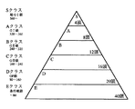
本実施形態では、内部的に100頭の馬が登録され、100頭分の馬データが保持されている。その内の12頭でレースが行われる。
図26(a)に示すように、100頭の馬は基本能力順に3タイプ6ランクに分けられたピラミッド構成をしている。超GI級のSクラス、GI級のAクラス、GII級のBクラス、GIII級のCクラス,OP級のDクラス、条件戦級のEクラスである。条件的には、SクラスとAクラス、BクラスとCクラスとDクラス、Eクラスとの3タイプに分けられる。
【0113】
基本能力値は、馬固有のものであり、どんなに勝って人気がでたとしても変わることはない。特定のレースから見れば、そのときの状況や条件、状態により、人気や力の上下関係は変わるが、長い目で見れば不変の「素質の差」「格の違い」とでもいうものである。
Sクラスとして4頭の馬が登録されている。Sクラスは360以上の基本能力値を有する超GI級である。登録馬専用の模型馬を有している。
【0114】
Aクラスとして8頭の馬が登録されている。Aクラスは320〜360の基本能力値を有するGI級である。GIレースの常連馬であり、基本的にGI路線のローテンションを組む。重賞レース(GIレース、GIIレース、GIIIレース)にしか出場しない。
Bクラスとして12頭の馬が登録されている。Bクラスは240〜320の基本能力値を有するGII級である。GIIレース、GIIIレースを足場としてGIレース勝利をもくろんでいる。得意な距離であればAクラスに匹敵する馬もいる。
【0115】
Cクラスとして16頭の馬が登録されている。Cクラスは160〜240の基本能力値を有するGIII級である。GIIレース、GIIIレースの中堅馬であり、Aクラスの馬にひとあわ吹かせたい。オープンレース、重賞レースを問わず出走する。
Dクラスとして20頭の馬が登録されている。Dクラスは80〜160の基本能力値を有するOP級である。オープンレース、GIIIレースを行ったり来たりしている。オープンレース、重賞レースを問わず出走する。
【0116】
Eクラスとして40頭の馬が登録されている。Eクラスは80以下の基本能力値を有する条件戦級である。オープンレースで好成績を上げないと重賞に出走できない。成績不振の馬は強制的に休養させられる。40頭のうち半数の20頭が放牧されていて出走しない。なお、Eクラスの馬は出走したレースの成績が悪いと強制的に放牧に出され、代わりの馬が入る。
【0117】
Eクラスの馬は20頭がローテーションに含まれないので、骨折等による故障馬がない最大の状態でも80頭によるローテーションとなる。12頭立てなので、平均6〜7レースに1回出走することになる(80÷12=6.66)。Eクラスの馬はその倍、平均13レースに1回出走する。
このように本実施形態の登録馬の構成によれば、登録馬を基本能力値にしたがって複数のランクに分け、そのランクに基づいて出走するレースを決めるので、本物の競馬のように多様ではあるが真実味のあるレースを組むことができる。
【0118】
(厩舎システム)
本実施形態の厩舎システムについて図27を用いて説明する。
上述したように、本実施形態では、内部的に100頭の馬が登録され、これら100頭の馬は基本能力順に6ランクに分けられたピラミッド構成をしている。本実施形態では、100頭の馬を厩舎を模擬したグループ分けし、各馬を特定の厩舎に所属するようにしている。例えば、図27に示すように、100頭の馬をA厩舎からL厩舎という12の厩舎に配分する。
【0119】
各厩舎に対しては、ローテーションの組み方、出走希望レースの選択等に対する特徴を持たせる。
厩舎によって、調子がよければ連続的に出走するような戦闘的な出走を試みる厩舎や、ローテーションを順守する厩舎等の性格を持たせる。これは出走希望レースに影響する。
【0120】
また、厩舎によって、スパルタ的な激しい調教を行う厩舎や、慎重な調教を行う厩舎等の性格を持たせる。調教パラメータに強く影響する。
また、厩舎によって、強気な出走レースを選択する厩舎や、堅実な出走レースを選択する厩舎や、距離適性を重視して出走レースを選択する厩舎等がある。出走希望ランクに影響する。
【0121】
このように、本実施形態によれば、登録馬を複数の厩舎に配分し、各厩舎に特徴を持たせることにより、出走希望レース、出走希望ランク、馬のパラメータ等に影響を与え、様々な要因を加味した多彩なレースを組むことができる。
(レース構成)
本実施形態のレース構成について図28を用いて説明する。
【0122】
本実施形態では、本物の競馬を模擬したレース構成を行う。レース構成として、前半18レース、後半18レースの合計36レースで構成され、この36レースが繰り返される。前半レースは、本物の競馬の春のレースを想定し、後半レースは、本物の競馬の秋のレースを想定している。
全36レースの距離、等級は、第28図に示す通りである。例えば、第1レースは中距離のGIIIレースであり、第2レースは長距離のOPレースであり、第3レースは中距離のGIIIレースであり、以下、第28図(a)に示すような順番で全36レースが構成される。長距離のGIIレースは前半にしかなく、短距離のGIIレースは後半にしかないのが特徴である。
【0123】
第18レース、第36レースは人気投票によるレースである。本物の競馬の宝塚記念レース、有馬記念レースを想定している。プレイヤによるベット数に基づいて出走馬を決定する。例えば、過去の18レースにおけるベット数が多かった上位8頭が出走する。残り4頭の枠を通常の方法で選出する。
これら36レースが繰り返される。
【0124】
全36レースの距離別構成は、長距離レースが6レース、中距離レースが24レース、短距離レースが6レースである。全36レースの等級別構成は、GIレースが6レース、GIIレースが8レース、GIIIレースが10レース、OPレースが12レースである。
このように、本実施形態によれば、本物の競馬のレース構成を模擬した多彩で変化のあるレース構成であるので、長時間プレイしていても飽きることがなく、本物の競馬レースと比較しながら楽しむことができる。
【0125】
(馬の能力値)
本実施形態の馬の能力値について図29乃至図31を用いて説明する。
従来の競馬ゲームでは、オッズは馬固有の能力値のみで決定されていた。前走の成績や短評にかかわらず能力値は同じであり、その結果、同じ組合せならオッズは同じであった。
【0126】
本実施形態では、馬の人気は能力値だけによるのではなく、状況に応じて人気が変動するようにした。特に、距離により人気が変動し、近年の成績により人気が変動する点を重要視している。
本実施形態では、馬の人気、抽選用能力を決定する核となる要素をメインファクタとし、メインファクタにプラスアルファのボーナスを与えるため要素をサブファクタとして定めている。
【0127】
(メインファクタ)
メインファクタには基本能力値と充実値がある。
基本能力値は、馬の絶対的な格付けを行うための値であり、馬が元来持っている素質である。基本的に基本能力値が高い馬が活躍する確率が高い。基本能力値は、長距離、中距離、短距離ごとに、個別に基本能力値をもたせる。
【0128】
基本能力値の具体例を図29に示す。
図29の1番の馬は、長距離の基本能力値が380で、中距離の基本能力値が300で、短距離の基本能力値が220である。1番の馬は、長距離の基本能力値が他の距離に比べて高い長距離馬である。
図29の2番の馬は、長距離の基本能力値が200で、中距離の基本能力値が260で、短距離の基本能力値が320である。2番の馬は、短距離の基本能力値が他の距離に比べて高い短距離馬である。
【0129】
図29の3番の馬は、長距離の基本能力値が80で、中距離の基本能力値が120で、短距離の基本能力値が70である。3番の馬は、中距離の基本能力値が他の距離に比べて高い中距離馬である。
図29の4番の馬は、長距離の基本能力値が190で、中距離の基本能力値が200で、短距離の基本能力値が190である。4番の馬は、距離の長短にかかわらず基本能力値が全体的に平均している万能場である。
【0130】
レース構成上、主となるのは中距離レースであるので、図26に示した基本能力クラスは中距離の基本能力値の高さによりランク分けされる。中距離の基本能力値が360以上の馬をSクラスとし、中距離の基本能力値が320〜360の範囲の馬をAクラスとし、中距離の基本能力値が240〜320の範囲の馬をBクラスとし、中距離の基本能力値が160〜240の範囲の馬をCランクとし、中距離の基本能力値が80〜160の範囲の馬をDクラスとし、中距離の基本能力値が80以下の馬をEクラスとする。
【0131】
充実値は、勝てば勝つほど人気がでるようにするために定めた値である。近走(例えば、前4走)の結果に基づいて定める。近走の内容がいいほどポイントが高い。レースの等級毎の着順に対して所定のポイントが定められる。着順がいいほどポイントが高く、レースのグレードが高いほどポイントが高くなるように定める。
【0132】
ポイント配分の具体例を図30に示す。
OPレースの場合、1位に10ポイント、2位に6ポイント、3位に4ポイント、4位に2ポイント、5位に1ポイント、6位に0ポイント、7位に−1ポイント、8位に−2ポイント、9位に−3ポイント、10位に−4ポイント、11位に−5ポイント、12位に−6ポイントが与えられる。
【0133】
GIIIレースの場合、プラスポイントはOPレースの倍であり、マイナスポイントはOPレースと同じである。1位に20ポイント、2位に12ポイント、3位に8ポイント、4位に4ポイント、5位に2ポイント、6位に0ポイント、7位に−1ポイント、8位に−2ポイント、9位に−3ポイント、10位に−4ポイント、11位に−5ポイント、12位に−6ポイントが与えられる。
【0134】
GIIレースの場合、プラスポイントはOPレースの4倍であり、マイナスポイントはOPレースと同じである。1位に40ポイント、2位に24ポイント、3位に16ポイント、4位に8ポイント、5位に4ポイント、6位に0ポイント、7位に−1ポイント、8位に−2ポイント、9位に−3ポイント、10位に−4ポイント、11位に−5ポイント、12位に−6ポイントが与えられる。
【0135】
GIレースの場合、プラスポイントはOPレースの8倍であり、マイナスポイントはOPレースと同じである。1位に80ポイント、2位に48ポイント、3位に32ポイント、4位に16ポイント、5位に8ポイント、6位に0ポイント、7位に−1ポイント、8位に−2ポイント、9位に−3ポイント、10位に−4ポイント、11位に−5ポイント、12位に−6ポイントが与えられる。
【0136】
充実値Rは、前4走のポイントから、例えば、次式により定められる。
R=a4×2+a3×3+a2×4+a1×5
ただし、a4:4走前のポイント
a3:3走前のポイント
a2:2走前のポイント
a1:1走前のポイント
なお、計算の結果、充実値Rが負となった場合には強制的にゼロとする。
【0137】
(サブファクタ)
サブファクタとして上昇度、馬場適性、距離適性、展開適性、調教度がある。図31に示すように、サブファクタ毎に5段階評価される。
上昇度は、調子が上昇中の馬かどうかをあらわすサブファクタである。近走の結果から評価する。急上昇していれば4ポイントとし、上昇気味であれば3ポイントとし、安定していれば2ポイントとし、下降気味であれば1ポイントとし、急下降中であれば0ポイントとする。
【0138】
距離適性は、距離に適性があるかどうかをあらわすサブファクタである。今回のレースの距離と、その馬の距離に対する基本能力値の比較とから評価する。今回のレースの距離が得意であれば4ポイントとし、やや得意であれば3ポイントとし、普通であれば2ポイントとし、やや苦手であれば1ポイントとし、苦手であれば0ポイントとする。
【0139】
馬場適性は、馬場状態に適性があるかどうかをあらわすサブファクタである。今回のレースの馬場状態と、その馬の馬場適性の比較から評価する。今回のレースの馬場状態が問題なければ4ポイントとし、たいして問題なければ3ポイントとし、やや問題であれば2ポイントとし、けっこう問題であれば1ポイントとし、大変問題であれば0ポイントとする。
【0140】
調教度は、現在の調子がいいかどうかをあらわすサブファクタである。ローテーション、調子の推移に基づいて評価する。所属する厩舎により異なる。最近の体調が絶好調であれば4ポイントとし、好調であれば3ポイントとし、平行線であれば2ポイントとし、不調であれば1ポイントとし、絶不調であれば0ポイントとする。
【0141】
展開特性は、レース展開、ペースに利があるかどうかをあらわすサブファクタである。今回のレースの出走メンバから予想されるペースと、その馬固有の脚質から評価する。今回のレースで予想される展開が有利であれば4ポイントとし、やや有利であれば3ポイントとし、普通であれば2ポイントとし、やや不利であれば1ポイントとし、不利であれば0ポイントとする。
【0142】
サブファクタは、抽選時に影響する可能性がある要素である。抽選結果に影響するしないにかかわらず、オッズには「影響する期待値」分が影響する。レース結果から見て、上位馬に何らかの共通要素が含まれることが多くなる。レース結果の上位馬から、例えば、今回のレースは重馬場が得意な馬で決まったというような類推が可能となる。
【0143】
(競馬ゲームの流れ)
本実施形態の競馬ゲームを全体の流れの概要を示す図32のフローチャートに沿って説明する。
(次レースの距離・グレードの決定)
まず、前述したレース構成にしたがって、次のレースの距離及びグレード(GI、GII、GIII、OP)を決定する(ステップS10)。
【0144】
(充実度の計算)
次に、登録された全ての馬について、前4走の結果から次レースの充実度を再計算する(ステップS11)。前述した充実値テーブルと前4走の結果に基づき、前述した充実値の式から計算する。
(出走希望ランクの決定)
次に、基本能力値と再計算した充実度から出走希望ランクを決定する(ステップS12)。
【0145】
出走希望ランクの決定方法の詳細について説明する。
本実施形態では希望登録制を採用している。各馬は基本能力値と充実度に基づいて出走するレースを選ぶ。原則的には希望した馬を優先して出走させる。しかしながら、本実施形態では、本物の競馬と異なり出走馬数が12頭固定であるため、希望が多いときには他のレースにまわし、少ないときには他のレースを希望する馬から連れてきて12頭にする必要がある。その調整を円滑に行うために、各馬について出走希望ランクを定め、レース終了後に更新するようにする。
【0146】
出走希望ランクとして4段階のランクを定める。ランクAは「ぜひ出走したい」ランクであり、ランクBは「出走してもよい」ランクであり、ランクCは「出走したくない」ランクであり、ランクDは「出走できない(出走資格がない)」ランクである。この4段階のランクを、4つのグレード別と、3つの距離別に、合計12通りのケースについて付ける。
【0147】
出走希望ランクの計算方法について説明する。
まず、レース終了後、各馬について充実値を再計算する。
次に、各馬について中距離について基本能力値と充実値を足した値から、中距離の希望ランクを決定する。この値が大きければ出走希望ランクは高くなるが、出走希望ランクの決め方は各馬が所属する厩舎によって異なる。例えば、同じ値であっても、強気の厩舎に所属する馬の場合は実力以上のレースに高いランクをつけるが、弱気の厩舎に所属する馬の場合は低いランクをつける。その結果、果敢に格上のレースに挑戦する馬もいれば、堅実に一歩一歩ステップアップを目指す馬がいるなど、本物の競馬と同様の状態を模擬できる。
【0148】
次に、中距離の希望ランクをもとに、距離適性を考慮し、長距離、短距離の希望ランクを決定する。すなわち、距離適性が低い場合、中距離に比べてランクは下がる。ただし、ランクCは変わらない。距離適性が高い場合、基本ランクより高いグレードではランクが下がり、低いグレードではそのままとする。この場合も、距離適性が高いか低いかの判断は所属する厩舎によって異なる。
【0149】
例えば、図33に示す、Bクラス(GII級)の馬の場合、中距離のGIIレースはランクAであり、GIレースはランクB、GIIIレースはランクB、OPレースはランクCとなる。長距離に適性があり、中距離は普通であり、短距離が不適性であるとすると、適性がある長距離の場合、長距離のGIレース、GIIレースはランクA、GIIIレースはランクB、OPレースはランクCとなる。不適性の短距離の場合、GIレース、GIIIレースはランクC、GIIIレースはランクB、OPレースはランクCとなる。
【0150】
なお、ランクDがつくのは、次のような場合である。例えば、基本能力がEクラスの馬がOPレースでも活躍できていない場合、OPレース以外では全てランクDとなる。また、基本能力がSクラス、Aクラスの馬はOPレースは常にランクDとなる。
上述したように、本実施形態では、中距離でのランク付けが基本となる。図34は、基本能力のクラスによる中距離のランク分類を示すものである。
【0151】
超GI級(基本能力値+充実値:N1〜)の馬の場合、GIレースはランクA、GIIレースはランクC、GIIIレースはランクC、OPレースはランクCである。
GI級(基本能力値+充実値:N2〜N1)の馬の場合、GIレースはランクA、GIIレースはランクB、GIIIレースはランクC、OPレースはランクCである。
【0152】
準GI級(基本能力値+充実値:N3〜N2)の馬の場合、GIレースはランクA、GIIレースはランクA、GIIIレースはランクB、OPレースはランクCである。
GII級(基本能力値+充実値:N4〜N3)の馬の場合、GIレースはランクB、GIIレースはランクA、GIIIレースはランクB、OPレースはランクCである。
【0153】
GII、GIII級(基本能力値+充実値:N5〜N4)の馬の場合、GIレースはランクB、GIIレースはランクA、GIIIレースはランクA、OPレースはランクBである。
GIII級(基本能力値+充実値:N6〜N5)の馬の場合、GIレースはランクC、GIIレースはランクB、GIIIレースはランクA、OPレースはランクBである。
【0154】
GIII、OP級(基本能力値+充実値:N7〜N6)の馬の場合、GIレースはランクC、GIIレースはランクB、GIIIレースはランクA、OPレースはランクAである。
OP級(基本能力値+充実値:N8〜N7)の馬の場合、GIレースはランクC、GIIレースはランクC、GIIIレースはランクB、OPレースはランクAである。
【0155】
基本能力がEクラスの馬(準OP級(基本能力値+充実値:N9〜N8)の場合、重賞出走権利がとれるまで、OPレースのみランクAで、GIレース、GIIレース、GIIIレースはランクDである。
基本能力がSクラス、Aクラスの馬は、OPレースは常にランクDである。
(出走希望レースの決定)
次に、図32に戻り、このようにして定めた各馬の出走希望ランクに基づいて、出走希望レースを決定する(ステップS13)。
【0156】
(レース出走馬の決定)
次に、各馬の出走希望レースに基づいて、レースの出走馬を決定する(ステップS14)。
レースの出走馬の決定方法について、図35のフローチャートを用いて説明する。
【0157】
まず、本レースの出走希望頭数が何頭いるかカウントする(ステップS30)。本レースの出走希望頭数が13頭以上であれば(ステップS31)、抽選により12頭を選出する(ステップS32)。落選した馬は別のレースを希望するようにして(ステップS33)、本レースの出走馬が決定される(ステップS34)。
【0158】
本レースの出走希望頭数がぴったり12頭であれば(ステップS35)、本レースの出走馬はその12頭にそのまま決定される(ステップS34)。
本レースの出走希望頭数が11頭以下で12頭に満たない場合(ステップS36)、次レースの出走希望馬に本レースの条件で希望ランクAの馬が何頭いるかカウントする(ステップS37)。ちょうど不足分いる場合には(ステップS38)、不足分を補充して(ステップS39)、本レースの出走馬が決定される(ステップS34)。不足分以上いる場合には(ステップS40)、抽選により不足分を決定して補充し(ステップS41)、本レースの出走馬が決定される(ステップS34)。
【0159】
次レース出走希望馬で本レースの条件で希望ランクAの馬が、不足分より少ない場合には(ステップS42)、取りあえずその分だけ補充し、次レースの出走希望馬が何頭いるかカウントする(ステップS44)
次レースの出走希望馬が13頭以上いる場合には(ステップS45)、次レース出走希望馬に本レースの条件で希望ランクBの馬が何頭いるかカウントする(ステップS46)。ちょうど不足分いる場合には(ステップS47)、不足分を補充して(ステップS48)、本レースの出走馬が決定される(ステップS34)。不足分以上いる場合には(ステップS49)、抽選により不足分を決定して補充し(ステップS50)、本レースの出走馬が決定される(ステップS34)。
【0160】
次レース出走希望馬で本レースの条件で希望ランクBの馬が、不足分より少ない場合には(ステップS53)、取りあえずその分だけ補充し、ステップS53に処理を移す。
ステップS44でカウントした次レースの出走希望馬が12頭以下の場合には(ステップS54)、ステップS53に処理を移す。
【0161】
ステップS53では、次々レースの出走希望馬に本レースの条件で希望ランクAの馬が何頭いるかカウントする。以降、ステップS38以降の処理をして(ステップS55)、本レースの出走馬を決定する(ステップS34)。
(人気投票)
人気投票による出走馬の決定方法について説明する。
【0162】
本物の競馬の宝塚記念レース、有馬記念レースを想定し、第18レース、第36レースを人気投票によるレースとする。人気投票レースの出走場はプレイヤによるベット数に基づいて決定する。ベット数のポイントとしては、単勝のベットがあったときは1ポイント、馬連のベットがあったときは0.5ポイント、枠連のベットがあったときは0.25ポイントとする。
【0163】
例えば、過去の18レースにおけるベット数が多かった上位12頭が出走する。ポイントが同数であったときは出走希望ランクによって出走馬を決定する。
また、出走する12頭のうち8頭は人気投票で選び、残り4頭の枠を通常の方法で選出するようにしてもよい。
人気投票レースがあるので、自分が好きな馬に多くベットすることにより、プレイヤの意志で人気投票レースに特定の馬を出走させることができる。
【0164】
(オッズの決定)
次に、次レースに出走する馬のメインファクタ及びサブファクタに基づいてオッズを決定する(ステップS15)。
オッズの算出方法について図36を用いて説明する。オッズには、メインファクタの基本能力値、充実度と、サブファクタの上昇度、距離適性、馬場適性、展開適性、
メインファクタ値Mは、本レースのグレード・距離における基本能力値をB、充実値をRとすると、次式
M=B+R
であらわされる。
【0165】
オッズ用サブファクタ率POは、上昇度のポイントをS1、距離適性のポイントをS2、馬場適性のポイントをS3、展開適性のポイントをS4、調教のポイントをS5とすると、次式
PO=(S1+S2+S3+S4+S5)×5
であらわされる。
【0166】
オッズ用修正能力値AOは、次式
AO=M+(M×PO/100)
であらわされる。
このオッズ用修正能力値AOを出走する全ての馬について算出し、各馬のオッズ用修正能力値AO1、AO2、…、AO12を得る。これらオッズ用修正能力値を用いてオッズを計算する。本実施形態では、1の馬の単勝オッズと、12頭を2頭ずつの6枠を分けた場合の枠連1−2のオッズWW1-2とを計算する。
【0167】
例えば、1の馬の単勝オッズW1は、次式
W1=(SAO/AO1)×(ペイアウト率)
ただし、オッズ用修正能力値の合計SAO=AO1+AO2+…+AO12
となる。
また、馬連1ー2のオッズWU1-2は、次式

【0168】
また、12頭を2頭ずつの6枠を分けた場合の枠連1−2のオッズWW1-2についても同様にして計算する。
(予想決定)
次に、次レースに出走する馬のメインファクタ及びサブファクタに基づいて予想屋が予想を決定する(ステップS16)。
【0169】
予想屋による予想方法について図37を用いて説明する。予想屋により重視するサブファクタが異なる。そのようにして求めた修正能力値を用いて予想を行い、予想印をつける。
予想屋1は前走結果を重視する予想屋であり、サブファクタのうち上昇度のポイントS1を重視し、他のサブファクタは考慮しない。したがって、予想屋1用修正能力値AOY1は、次式
AOY1=M+{M×((S1)×K1)/100}
であらわされる。ただし、K1は定数である。
【0170】
この予想屋1用修正能力値AOY1を出走する全ての馬について算出し、各馬の予想屋用修正能力値AOY1,1、AOY1,2、…、AOY1,12を得る。これら予想屋用修正能力値を用いて予想を行い、予想印を付す。
予想屋2は適性を重視する予想屋であり、サブファクタのうち距離適性のポイントS2と馬場適性のポイントS3を重視し、他のサブファクタは考慮しない。したがって、予想屋1用修正能力値AOY2は、次式
AOY2=M+{M×((S2+S3)×K2)/100}
であらわされる。ただし、K2は定数である。
【0171】
この予想屋2用修正能力値AOY2を出走する全ての馬について算出し、各馬の予想屋用修正能力値AOY2,1、AOY2,2、…、AOY2,12を得る。これら予想屋用修正能力値を用いて予想を行い、予想印を付す。
予想屋3は展開を重視する予想屋であり、サブファクタのうち展開適性のポイントS4を重視し、他のサブファクタは考慮しない。したがって、予想屋3用修正能力値AOY3は、次式
AOY3=M+{M×((S4)×K3)/100}
であらわされる。ただし、K3は定数である。
【0172】
この予想屋3用修正能力値AOY3を出走する全ての馬について算出し、各馬の予想屋用修正能力値AOY3,1、AOY3,2、…、AOY3,12を得る。これら予想屋用修正能力値を用いて予想を行い、予想印を付す。
予想屋4は調子を重視する予想屋であり、サブファクタのうち調子のポイントS5を重視し、他のサブファクタは考慮しない。したがって、予想屋4用修正能力値AOY4は、次式
AOY4=M+{M×((S5)×K4)/100}
であらわされる。ただし、K4は定数である。
【0173】
この予想屋4用修正能力値AOY4を出走する全ての馬について算出し、各馬の予想屋用修正能力値AOY4,1、AOY4,2、…、AOY4,12を得る。これら予想屋用修正能力値を用いて予想を行い、予想印を付す。
なお、上述した予想屋1〜予想屋4の特徴は例示であって、どのサブファクタをどの程度重視して予想するようにしてもよい。また、同じ予想屋であっても変化させてもよい。
【0174】
(抽選→勝ち馬と順位決定)
次に、レースに出走する馬のメインファクタ及びサブファクタに基づいて抽選を行い勝ち馬と順位を決定する(ステップS17)。影響するサブファクタの個数、種類、影響の程度を乱数により変化させ、それに基づく修正能力値によって抽選を行い、1着2着の勝ち馬と12頭全ての順位を決定する。
【0175】
メインファクタ値Mは、オッズのときと同様に、本レースのグレード・距離における基本能力値をB、充実値をRとすると、次式
M=B+R
であらわされる。
抽選用サブファクタ値SLOTは、上昇度のポイントS1の影響度をP1、距離適性のポイントS2の影響度をP2、馬場適性のポイントS3の影響度をP3、展開適性のポイントS4の影響度をP4、調教のポイントS5の影響度をP5とすると、これらの値の関数として求められる。
【0176】
抽選用修正能力値LOTは、上述したメインファクタ値M及び抽選用サブファクタ値SLOT等の関数として求められる。
この抽選用修正能力値LOTを出走する全ての馬について算出し、各馬の抽選用修正能力値LOT1、LOT2、…、LOT12を得る。抽選用修正能力値の例を図39に示す。
【0177】
これら抽選用修正能力値に基づいて抽選を行う。
(レース展開決定)
次に、勝ち馬と順位が決定されると、その結果に基づいてレース展開を決定する(ステップS18)。従来の競馬ゲームでは、順位が決定すると、決定した順位になるように各馬のペースで走行していた。本実施形態では、決定した順位だけではなく、勝ち馬の脚質や出走馬の組合せ、距離、馬場状態等の要素も加味してレース展開を決定する。
【0178】
レース展開の決定方法の具体例について説明する。
12頭の出走馬に対してレーステーブルが用意してある。レーステーブルは経過時間と走行距離のデータが格納されたテーブルである。各馬について、所定時間間隔での走行距離のデータを格納されている。
まず、距離テーブルの内容を全ての出走馬のレーステーブルに写す。距離テーブルには、レースの距離に応じて経過時間と走行距離のデータが格納されている。この段階では全ての出走馬のレーステーブルは同じである。
【0179】
次に、出走馬全体の脚質や抽選により決定された着順に基づいて、レースのペースを決定する。
次に、決定されたペースをもとに各出走馬のレーステーブルを補正する。例えば、抽選の結果、逃げ切り馬が1着の場合には、スローペースでレースを展開するように各出走馬のレーステーブルを補正する。また、先行馬が多いレースの場合には、ハイペースでレースを展開するように各出走馬のレーステーブルを補正する。
【0180】
次に、各出走馬の持っている固有の距離特性と脚質等を考慮して、レーステーブルを補正する。各出走馬の別のファクタ、例えば、馬場適性、コンディション等と着順を考慮してレーステーブルを更に補正する。
次に、補正された各出走馬のレーステーブルに対して、キャリアの最高スピードを超えないようになっているかどうかを検証し、越えているものがあれば再度補正する。
【0181】
このようにして求めた各出走馬のレーステーブルにより、個々の走破タイムが計算される。そのレーステーブルから単位時間(例えば0.5秒)毎の各馬の位置、前に進む方向を算出し、各馬の位置をシミュレートする。その結果、衝突することがあれば、例えば、斜めに進む方向の動き等を加えて、キャリアが衝突しないようにレースデータを補正して完成する。
【0182】
(ベット受付終了)
次に、ベット開始から所定時間が経過すると、ベットの終了時間が迫っていることを知らせて一定時間が経過した後、ベットの受付を終了する(ステップS19)。
(レース実行)
次に、各出走馬のレーステーブルに従ってレースを実行する(ステップS20)。レース中は実況アナウンスが行われ、馬足音が発せられ、光る芝による演出が加えられる。既に決定されたレーステーブルに基づいて、実況アナウンス、馬足音、光る芝を駆動制御してもよいが、本実施形態では模型馬の現在の検出位置に基づいて、実況アナウンス、馬足音、光る芝を駆動制御するようにしている。不慮の事故により模型馬の走行状態が変動しても対応することができる。
【0183】
(データ更新)
次に、実際のレース結果に基づいて、各出走馬のデータを更新する(ステップS21)。本実施形態では、抽選結果ではなく現実に行われたレース結果に基づいてデータを更新する。例えば、装置のトラブルから特定の馬が予定通り走行できなくなり抽選結果と異なる走行結果になった場合でも、現実の走行結果に基づいてデータを更新する。
【0184】
(払い戻し)
次に、実際のレース結果に基づいて、プレイヤに対してオッズに応じた払い戻しを行う(ステップS22)。本実施形態では、払い戻しにおいても、現実の走行結果に基づいて払い戻しを行うようにする。
(過去のレースを再現)
レース前の雰囲気を盛り上げ、より臨場感を持たせるために、ベット中に大型プロジェクタ24を用いて過去に行ったレースを再現する。単に直前のレースを再現するようにしてもよいが、本実施形態では、ステップS14でレース出走馬が決定した後に、出走馬に関する過去のレースを再現する(ステップS23)。ステップS23のレース再現は、ステップS19でベット受付が出力するまで行われる。
【0185】
再現するレースとしては、プレイヤによるベットの参考となり、レース前の雰囲気を盛り上げるものが望ましい。
例えば、レース出走馬中、前走で1着の馬があれば、その馬に関する前走のレースを再現する。プレイヤがベットの参考にすることができる。
また、レース出走馬中、オッズの高い馬について、その馬がよい成績を得たときのレースを再現したり、オッズが高い馬であって過去に対戦した複数の出走馬が含まれていれば、そのときのレースを再現したりする。オッズの高い馬への期待度を高め、コイン収集度を高めることができる。
【0186】
また、重賞レースの場合には、過去の重賞レースを再現する。重賞レースへの期待を高めることができる。
レースの再現にあたっては、レースの模様を大型プロジェクタ24を用いて再現するだけでなく、実況中継、馬蹄音、歓声等の音を発生するようにして雰囲気を盛り上げるようにする。
【0187】
[第2実施形態]
(競馬ゲーム装置)
本発明の第2実施形態による競馬ゲーム装置について図40乃至図47を用いて説明する。上述した第1実施形態による競馬ゲーム装置と同一又は類似の構成要素には同一の符号を付して説明を省略又は簡略にする。
【0188】
(競馬ゲーム装置全体の外観)
競馬ゲーム装置全体の外観を図40に示す。
競馬ゲーム装置10の中央には、競馬用の環状のトラック12が設けられている。トラック12上を6頭の模型馬14が走行する。トラック12内にはゲート(図示せず)が設けられ、レースのスタート時にトラック12のスタート位置に進出する。
【0189】
トラック12の周囲には10席のサテライト22が設けられている。トラック12の長辺の両側にそれぞれ5席のサテライト22が設けられている。
トラック12の短辺の一方の側には、レースの状況等の画像を写し出す大型プロジェクタ24が設けられている。大型プロジェクタ24の両側には実況放送やファンファーレ、BGM等のためのスピーカ(図示せず)が設けられている。
【0190】
トラック12上方には、トラック12や模型馬14を照明するためのトラック照明部400が設けられている。トラック照明部400はトラック形状をしており、トラック12の4隅に立てられた支柱401により支えられている。
(競馬ゲーム装置全体の構成)
競馬ゲーム装置全体の構成を図41のブロック図に示す。
【0191】
図2に示す第1実施形態における、光る芝60、光る芝ドライバ58、光る芝制御部56の代わりに、トラック12や模型馬14を照明するためトラック照明部400と、トラック照明部400を制御するトラック照明制御部402とが設けられている。その他の構成については第1実施形態と同様である。
トラック照明制御部402は主ネットワークCPU30に接続されている。トラック照明部400は、トラック12を照明して浮き上がらせる効果をだしたり、先頭を走る模型馬14を光で追跡して照明効果を演出する。
【0192】
(トラック照明部(その1))
競馬ゲーム装置10のトラック照明部400の構成を図42に示す。
本実施形態のトラック照明部400は、図42(a)に示すように、トラック12上方に設けられている。多数個のランプ404がトラック状に配列されている。各ランプ404は、その照明方向がトラック12の各部分を照明するように調整されている。多数個のランプ404を順番に点灯すると、トラック12上でスポットライトが周回する。
【0193】
多数個のランプ404は、照明に使用する色のランプを適宜配列してもよい。例えば、図42(b)に示すように、白色のランプ404a、赤色のランプ404b、青色のランプ404cの順番で配列する。多数個のランプ404を順番で点灯すると、トラック12上を照明スポットが色調を変えながら周回する。競馬ゲームの進行に応じて照明すると、照明スポットが競馬ゲームの先頭馬を追跡する。
【0194】
また、多数個のランプ404を、光の三原色である、赤色のランプ、緑色のランプ、青緑色のランプを一組として多数組設けてもよい。この場合、ランプ404の点灯制御は、光の三原色である3個のランプを一組として行われる。3個のランプの点灯を制御することにより、所望の色調で照明することができる。
トラック照明部400による照明制御の一例について説明する。
【0195】
レースが開始するまでは、プレイヤの参加を促すと共に、レース開始前のベット時間を演出するように照明する。例えば、芝色のトラック12を明るく照明したり、スポットライトがトラック12上で周回するように照明したりする。なお、トラック12を白色にして、トラック照明部400の照明により所望の色となるようにしてもよい。例えば、鮮やかな芝色や、ダートの茶色等、レースコンディションにより自由に色を変更することができる。
【0196】
レースを開始するために、模型馬14がゲート近傍に集まると、トラック照明部400はゲート近傍を集中的に照明する。
レースが開始すると、トラック照明制御部400は、位置検出部40により検出された現在の先頭馬14の位置に対応したランプ404を点灯して、先頭馬にスポットライトを当てる。
【0197】
レースが終了すると、レース結果の興奮を演出するように照明する。例えば、トラック12全体をフラッシュ状に照明したり、照明スポットがぐるぐる回るように照明したりする。また、勝利した模型馬14がウイニングランとしてトラック12上を一周する際には、トラック照明部400は、ウイニングランする模型馬14を追跡してスポットライトを当てる。
【0198】
このように、本実施形態のトラック照明部によれば、映像や、BGMや馬足音等の音声に加えて、模型馬が走るトラック全体を光らせたり、走っている模型馬にスポットを当てたりすることにより、更に迫力あるレースを実現することができる。
(トラック照明部(その2))
競馬ゲーム装置10のトラック照明部400の他の具体例を図43に示す。
【0199】
本具体例では、複数のファイバを束ねてトラック照明アーム410を構成している。トラック照明アーム410は、図43に示すように、コーナーからトラック12上方に延びるように形成されている。トラック照明アーム410の先端は、駆動装置(図示せず)により自在に駆動され、照明方向を自在に変更する。
トラック照明アーム410の他端にはランプ412が設けられている。トラック照明アーム410とランプ412の間には、円形のフィルタ414が設けられている。フィルタ414はモータ416により回転駆動する。ランプ412の光はフィルタ414を介してトラック照明アーム410の他端に入射する。モータ416によりフィルタ414を回転することにより、トラック12上に照射される照明光の強度や色調が変化する。
【0200】
トラック照明部400における照明制御の一例について説明する。
レースが開始するまでは、プレイヤの参加を促すと共に、レース開始前のベット時間を演出するように照明する。例えば、トラック照明アーム410の先端を旋回してスポットライトがトラック12上で周回するように照明したりする。
レースが開始すると、トラック照明制御部402は、位置検出部40により検出された現在の先頭馬14の位置に基づいてトラック照明アーム410の先端を動かし、先頭馬にスポットライトを当てる。
【0201】
レースが終了すると、レース結果の興奮を演出するように照明する。例えば、フィルタ414を回転して色を変化しながら、トラック照明アーム410の先端を旋回して、トラック12上で色を変化しながら、照明スポットがぐるぐる回るように照明したりする。また、勝利した模型馬14がウイニングランとしてトラック12上を一周する際には、トラック照明アーム400は、ウイニングランする模型馬14を追跡してスポットライトを当てる。
【0202】
このように、本具体例のトラック照明部によれば、映像や、BGMや馬足音等の音声に加えて、走っている模型馬にスポットを当てたりすることにより、更に迫力あるレースを実現することができる。
(トラック照明部(その3))
競馬ゲーム装置10のトラック照明部の更に他の具体例を図44に示す。
【0203】
本具体例では、トラック12の内周と外周に、横方向から光が出射するファイバ420、424を設けている。ファイバ420の端部には光源422が設けられ、ファイバ424の端部には光源426が設けられている。
光源422、426の光はファイバ420、424の側方からで射し、これによりトラック12が照明される。トラック照明制御部402により光源422、426が制御される。光源422、426の強度や色調が変化すると、トラック12の照明光の強度や色調が変化する。
【0204】
本具体例のトラック照明部によれば、映像や、BGMや馬足音等の音声に加えて、競馬ゲームのレース進行に伴って、トラックの色調を自在に変化することができ、迫力あるレースを実現することができる。
なお、本具体例のトラック照明部は単独で用いてもよいが、上述したトラック照明部(その1)又はトラック照明部(その2)と併せて用いると更に効果的である。
【0205】
(サテライト)
本実施形態による競争ゲーム装置10のサテライト22について図45乃至図47を用いて説明する。図45は競争ゲーム装置10のサテライト22の配置構成を示す図、図46はサテライト22の内部構成を示す図、図47はサテライト22の前面パネルの構造を示す図である。
【0206】
本実施形態の競争ゲーム装置10では、図45に示すように、トラック12の短辺側の下部にメインコントロールボード500が設けられている。メインコントロールボード500には、図41に記載された制御回路等が搭載されている。
トラック12の長辺の両側には5席のサテライト22が設けられている。トラック12の長辺側の下部には、それぞれ5席のサテライト22用の直流電源502が設けられている。1台の直流電源502から5台のサテライト22に直流電力が供給されている。図示しないが、直流電源502の近傍には、各サテライト22用に交流コンセントが設けられている。
【0207】
サテライト22の内部構成を図46に示す。サテライトボード510は、サテライト22全体を制御する制御回路等を搭載している回路ボードである。サテライトボード510には、画像を表示するモニタ512と、モニタ512の表面に設けられ、プレイヤが指示入力するためのタッチパネル514と、メダルを供給するメダルホッパー516と、音声を出力するスピーカ518とが接続されている。
【0208】
サテライト22は交流電力と直流電力を必要とする。交流電力は交流用コネクタ520から供給される。交流用コネクタ520は、交流用電源スイッチ522を介してモニタ512に接続されている。交流用コネクタ520は外部の交流コンセントに接続されている。
直流電力は直流用コネクタ530から供給される。直流用コネクタ530は、直流用電源スイッチ532、サーキットプロテクタ534を介したサテライトボード510に接続されている。直流用コネクタ530は外部の直流電源502に接続されている。
【0209】
交流用電源スイッチ522及び直流用電源スイッチ532は、保守を行うサービスマンが操作するスイッチであって、サテライト22の筐体内のプレイヤが操作できない位置に設けられている。
これら交流用電源スイッチ522と直流用電源スイッチ532は通常はオン状態になっており、競争ゲーム装置の主電源のスイッチをオンにすると、各サテライト22にも電力が供給される。モニタ512に交流電力が供給され、サテライトボード510に直流電力が供給される。
【0210】
サテライト22の電源をオフにする場合、交流電力については単に交流用電源スイッチ522をオフにして問題ないが、直流電力についてはサテライトボード510において電源遮断時の処理、例えば、環境設定の保存、データ待避等を行う必要があるため、直流用電源スイッチ532をオフにして直流電力を直ちに遮断することができない。
【0211】
このため、本実施形態では、サテライトボード510に、サテライト22のドア(図示せず)の開閉に連動したドアスイッチ536を設けている。交流用電源スイッチ522及び直流用電源スイッチ532を操作するためにドアを開けなければならないから、交流用電源スイッチ522又は直流用電源スイッチ532がオフされる前には必ずドアスイッチ536がオフになる。
【0212】
本実施形態では、このことを利用し、ドアが開けられてドアスイッチ536がオフになると、サテライトボード510は電源遮断処理を行うようにしている。これにより、続いて、直流用電源スイッチ532をオフにしても問題がなく、再起動時には、電源遮断前の状態に戻すことができる。また、故障が起きた場合でも、その故障状態を的確に把握することができる。
【0213】
なお、ドアスイッチ536を設ける代わりに、直流用電源スイッチ522を一定期間経過してから遮断されるような遅延スイッチにしてもよい。また、直流電源を供給する配線に大きなコンデンサを接続して、実質的に電源の遮断を遅延させるようにしてもよい。
また、本実施形態のサテライト22には直流用電源スイッチ532とサテライトボード510の間にサーキットプロテクタ534を設けている。これは、直流電源502を共有しているため、他のサテライト22のトラブルにより過電流が流れてサテライトボード510が破壊するのを防止するためである。
【0214】
サテライト22の前面パネル550の構造を図47に示す。サテライト22の前面パネル550には、メダル払い出し口551が設けられている。メダル払い出し口551上方にはメダルホッパー516の払い出し口554が設けられている。メダル払い出し口551下部には、メダルカップ556を載置するためのカップ受け552が設けられている。
【0215】
プレイヤは自分のメダルカップ556をカップ受け552に置いておき、必要に応じてメダルカップ556からメダルを取りだして使用する。メダルホッパー516から供給されたメダルは自動的にメダルカップ556に貯まり、メダル管理を容易に行うことができる。
このように、本実施形態では各サテライトに電源を設けるのではなく、複数のサテライトにひとつの電源を設けたので、設置スペースが小さくて済み、コストを節約することができる。また、本実施形態によればドアスイッチを設け、ドアスイッチのオフにより電源遮断処理を開始するようにしたので、電源遮断時の環境設定の保存したり、データ待避等を行うことができ、再起動時には、電源遮断前の状態に戻すことができる。更に、前面パネルのメダル払い出し口にメダルカップ受けを設けたので、ゲーム中において邪魔なメダルカップを置くことができ、しかも、払い出されたメダルを自動的に受け取ることができる。
【0216】
なお、本実施形態は競争ゲーム装置のサテライトを例として説明したが、競争ゲーム装置以外のゲーム装置、例えば、複数のプレイヤが参加してゲームを行うビンゴゲームやブラックジャックゲーム等を行うゲーム装置のサテライトに本発明を適用してもよい。
(競馬ゲーム)
本発明の第2実施形態による競馬ゲームについて図48乃至図51を用いて説明する。
【0217】
本実施形態の競馬ゲームは、上述した競馬ゲーム装置を用い、レース開始前の映像を工夫して、着順を予想する面白さを追求すると共に予想しやすくしたものである。
本実施形態の競馬ゲームの流れを図48のタイムチャートに沿って説明する。1レースを2分で行う場合について説明する。
【0218】
全体の流れとしては、1レース時間の0秒から45秒の間がベット時間であり、45秒から100秒の間がレース時間であり、100秒から120秒の間が確定時間である。なお、40秒から45秒の間がゲートイン時間である。
大型プロジェクタ24には、1レース時間の0秒から5秒の間でコース紹介をし、5秒から25秒の間でパドック映像を映し出す。パドック映像は、例えば、図49に示すようなものであり、出走馬一頭毎に、全出走馬について、その能力や、気性や、現在の体調等を反映させた映像を映し出し、プレイヤの予想の参考とする。例えば、馬の動きにより気性を反映させたり、馬体の大きさや、毛艶等により現在の体調を反映させる。なお、図49では一頭ずつ映すようにしたが、2頭ずつや3頭ずつ映してもよいし、パドック全体を映して全出走馬を同時に映すようにしてもよい。パドック映像の表示方法の具体例については後述する。
【0219】
パドック映像による全出走馬の紹介を終了した後の25秒から40秒の間は、大型プロジェクタ24で、プレイヤの予想に直接関連しない各種情報紹介をする。プレイヤは、パドック映像を見た後、この各種情報紹介している間にゆっくりと考えてベットを行うことができる。このように、本実施形態では、パドック映像とレース開始の間に、予想に関連しない各種情報紹介映像を映し出す時間を設けて、プレイヤに対しベット時間を確保している。各種情報紹介としては、例えば、騎手の情報や、プレイヤ中の最高当たり枚数や、前5レースの結果や、場内の風景等である。
【0220】
大型プロジェクタ24には、レース直前の40秒から45秒の間で出走馬の体勢完了状態を表示し、次の45秒から100秒の間でレースの状態を表示し、100秒から120秒の間で確定映像を表示する。
サウンドとしては、実況放送出力部36及び馬足音発生部38により各種の音を出力し雰囲気を盛り上げる。1レース時間の0秒から40秒の間はBGMを出力し、40秒から実況放送を開始し、40秒から45秒の間ではファンファーレを出力し、歓声を出力する。レース中の45秒から100秒の間は実況放送を出力すると共に、馬足音発生部38からギャロップ(馬足音)を出力する。100秒から120秒の間では確定放送を出力する。なお、必要に応じて適宜、野次を出力するようにしてもよい。
【0221】
模型馬14の機構としては、1レース時間の10秒から40秒の間でスタート位置に移動し、40秒から45秒の間でゲートインし、45秒から100秒の間でレースを行うように制御される。
スタートゲート18としては、40秒から45秒の間で横移動してコース上にゲートを設置し、レース開始後の55秒から65秒の間で横移動してコース上から所定位置に収納される。
【0222】
なお、上記実施形態では、大型プロジェクタ24に、パドック映像を映し出した後に各種情報紹介映像を映し出したが、順番を逆にして、各種情報紹介映像を映し出した後にパドック映像を映し出すようにしてもよい。
次に、パドック映像の表示方法の具体例について、図50及び図51を用いて説明する。図50は本具体例によるパドック映像の表示方法のフローチャート、図51はパドック映像の確率テーブルを示す図である。
【0223】
本実施形態では、出走馬の能力や、気性や、現在の体調等を反映させた映像を生成するようにしている。馬の様々な動作をあらわす映像を単位映像として複数種類設定し、これら単位映像を、上述したパラメータに基づいて組合せて、パドック映像を生成する。
本具体例では、出走馬の気性のパラメータに基づいたパドック映像の生成方法について説明する。
【0224】
馬の動作をあらわす単位映像としては、図51に示すように、全体動作として8種類、尻尾動作として3種類を設定する。8種類の全体動作を2つのカテゴリーに分類している。全体動作の第1カテゴリーは首をあげる動作に関するもので、「首をあげる」「同(首をあげて)横向き」「同(首をあげて)立ち止まり」「同(首をあげて)首振りからうなだれる」の4つの動作映像が含まれている。全体動作の第2カテゴリーは首をうなだれる動作に関するもので、「首をうなだれる」「同(首をうなだれて)横向き」「同(首をうなだれて)立ち止まり」「同(首をうなだれて)首振りから首をあげる」の4つの動作が含まれている。尻尾動作には、尻尾を「垂らす」「振る」「振り回す」の3つの動作が含まれている。
【0225】
本実施形態のパドック映像の表示方法は、これら動作映像を、図51に示す確率に応じて選択して表示する。図51のテーブルでは、馬の気性に応じて、動作映像が選ばれる確率が変化している。気性のおとなしい馬は、特定の動作映像、例えば、おとなしい動作映像の確率が高くなり、その他の動作映像の確率が低くなっている。特定の動作映像の確率が高くなれば、同じ動作が選ばれやすくなり動作の変化が少なくなる。気性の荒い馬は、おとなしい動作映像(例えば、首をあげて立ち止まり、首をうなだれ立ち止まり)を除いた全ての動作映像について同等な確率が設定されている。異なる動作が選ばれやすくなり、落ち着かない動作となる。
【0226】
次に、パドック映像の生成方法について、図50のフローチャートを用いて説明する。
最初は、全体動作については第1カテゴリーと第2カテゴリーを含む8つの動作からひとつの動作が、尻尾動作について3つの動作からひとつの動作が、抽選される(ステップS100)。馬の気性に応じた図50のテーブルの確率にしたがって選ばれる。次に、選ばれた動作が大型プロジェクタ24に表示される(ステップS101)。
【0227】
次に、全体動作の抽選結果が第1カテゴリーに関するものか、第2カテゴリーに関するものか判断する(ステップS102)。第1カテゴリーに関するものとは、なめらかな動作となるように、次の動作が第1カテゴリーから選ばれるべき動作である。具体的には、第1カテゴリーの「首をあげる」「同(首をあげて)横向き」「同(首をあげて)立ち止まり」と、第2カテゴリーの「同(首をうなだれて)首振りから首をあげる」の4つの動作である。第2カテゴリーに関するものとは、なめらかな動作となるように、次の動作が第2カテゴリーから選ばれるべき動作である。具体的には、第1カテゴリーの「同(首をあげて)首振りからうなだれる」と、第2カテゴリーの「首をうなだれる」「同(首をうなだれて)横向き」「同(首をうなだれて)立ち止まり」の4つの動作である。
【0228】
全体動作の抽選結果が第1カテゴリーに関する動作の場合は、ステップS103で、全体動作については第1カテゴリーに属する4つの動作からひとつの動作が、尻尾動作について3つの動作からひとつの動作が、抽選される。馬の気性に応じた図50のテーブルの確率にしたがって選ばれる。次に、選ばれた動作が大型プロジェクタ24に表示される(ステップS104)。
【0229】
次に、パドック映像の表示時間が終了したか否か判断し(ステップS105)、表示時間が終了していれば直ちに終了する。表示時間が終了していなければ、全体動作の抽選結果が「同(首をあげて)首振りからうなだれる」動作となるまでステップS103からS106が実行され、第1カテゴリー内の動作が選ばれ続ける。全体動作の抽選結果が「同(首をあげて)首振りからうなだれる」動作であると判断されると、ステップS107に処理が移る。
【0230】
全体動作の抽選結果が第ふカテゴリーに関する動作の場合は、ステップS10やで、全体動作については第2カテゴリーに属する4つの動作からひとつの動作が、尻尾動作について3つの動作からひとつの動作が、抽選される。馬の気性に応じた図50のテーブルの確率にしたがって選ばれる。次に、選ばれた動作が大型プロジェクタ24に表示される(ステップS108)。
【0231】
次に、パドック映像の表示時間が終了したか否か判断し(ステップS109)、表示時間が終了していれば直ちに終了する。表示時間が終了していなければ、全体動作の抽選結果が「同(首をうなだれて)首振りから首をあげる」動作となるまでステップS107からS110が実行され、第2カテゴリー内の動作が選ばれ続ける。全体動作の抽選結果が「同(首をうなだれて)首振りから首をあげる」動作であると判断されると、ステップS103に処理が移る。
このようにして、全体動作を2つのカテゴリーに分け、そのカテゴリー内で動作を選ぶようにしたので、馬が自然な動作をし、しかも、その動作を見て気性を見分けることができる。
【0232】
なお、上述した説明では、常に、馬の気性に応じた図51のテーブルにしたがって抽選を行ったが、プレイヤによる予想を混乱させるために、図51のテーブルの確率に反する及び/又は依存しない確率により抽選するようにしてもよい。この確率の値や抽選回数を変化して予想の難易度を調節することができる。
[変形実施形態]
本発明は上記実施形態に限らず種々の変形が可能である。
【0233】
例えば、上記実施形態では、本発明を競馬ゲームに適用したが、競馬以外の競艇や、自動車レース、オートレース等の競争ゲームにも適用することが可能である。
また、上記実施形態では、実際に模型の走行体を走行させる競争ゲームに本発明を適用したが、家庭用のゲームを用いた競争ゲームに上述した競争ゲーム方法を適用してもよい。競争ゲーム方法を実現するプログラムは、CD−ROM、ゲームカートリッジ等の記憶媒体により提供されてもよいし、通信回線を介して提供されてもよい。
【0234】
【発明の効果】
以上の通り、本発明によれば、多彩なレースの組合せを可能とすると共に、レース結果により人気が変動するようにし、着順を予想する面白さやレース展開の面白さを更に追求した競争ゲーム方法を実現することができる。
【図面の簡単な説明】
【図1】本発明の第1実施形態による競馬ゲーム装置全体の外観図である。
【図2】本発明の第1実施形態による競馬ゲーム装置全体の構成を示すブロック図である。
【図3】競馬ゲーム装置の馬足音発生部の構成を示す図である。
【図4】馬足音発生部の各スピーカにおける音源の音の大きさの具体例を示す図である。
【図5】競馬ゲーム装置の位置検出部の構成を示す図である。
【図6】競馬ゲーム装置の位置検出部を説明するための断面図である。
【図7】競馬ゲーム装置の赤外線出力部の構成を示す図である。
【図8】競馬ゲーム装置の赤外線出力部を説明するための断面図である。
【図9】競馬ゲーム装置の光る芝の構成を示す図である。
【図10】競馬ゲーム装置の光る芝を説明するための断面図である。
【図11】競馬ゲーム装置のサテライトを上方から見た図である。
【図12】競馬ゲーム装置のサテライトで表示されるゲーム画面の一例を示す図である。
【図13】競馬ゲーム装置のサテライトで表示されるゲーム画面の他の例を示す図である
【図14】競馬ゲーム装置のサテライトの構成を示すブロック図である。
【図15】競馬ゲーム装置の出走ゲートの構成を示す図である。
【図16】競馬ゲーム装置の出走ゲートの動作を説明する斜視図である。
【図17】競馬ゲーム装置の模型馬の台車とキャリアの構造を示す断面図である。
【図18】競馬ゲーム装置の模型馬の台車とキャリアの構造を示す図であり、図18(a)は模型馬の台車の底面図、図18(b)はキャリアの平面図、図18(c)はキャリアの中央近傍の断面図である。
【図19】競馬ゲーム装置のキャリアのブロック図である。
【図20】競馬ゲーム装置の模型馬の構造を示す図である。
【図21】模型馬の一部の機構を説明するための斜視図である。
【図22】競馬ゲーム装置の模型馬の構造であって、模型騎手が鞭を振り上げたときの状態の構造を示す図である。
【図23】模型馬の一部の機構を説明するための斜視図である。
【図24】模型馬の一部の機構を説明するための斜視図である。
【図25】競馬ゲーム装置の模型馬の構造であって、模型騎手が立ち上がったときの状態の構造を示す図である。
【図26】本発明の第1実施形態による競馬ゲームにおける登録馬の構成の説明図である。
【図27】競馬ゲームにおける登録馬の構成の説明図である。
【図28】競馬ゲームにおけるレース構成の説明図である。
【図29】競馬ゲームにおける馬の能力値におけるメインファクタの基本能力値についての説明図である。
【図30】競馬ゲームにおける馬の能力値におけるメインファクタの充実度についての説明図である。
【図31】競馬ゲームにおける馬の能力値におけるサブファクタについての説明図である。
【図32】競馬ゲームにおける全体の流れの概要を示すフローチャートである。
【図33】競馬ゲームにおける馬の出走希望ランクについての説明図である。
【図34】競馬ゲームにおける馬の出走希望ランクについての説明図である。
【図35】競馬ゲームにおけるレースの出走馬の決定方法を示すフローチャートである。
【図36】競馬ゲームにおけるオッズ用の修正能力値の算出方法についての説明図である。
【図37】競馬ゲームにおける予想屋による予想方法についての説明図である。
【図38】競馬ゲームにおける抽選用の修正能力値の算出方法についての説明図である。
【図39】競馬ゲームにおける抽選用の修正能力値の具体例を示す図である。
【図40】本発明の第2実施形態による競馬ゲーム装置全体の外観図である。
【図41】本発明の第2実施形態による競馬ゲーム装置全体の構成を示すブロック図である。
【図42】競馬ゲーム装置のトラック照明部の一具体例の構成を示す図である。
【図43】競馬ゲーム装置のトラック照明部の他の具体例の構成を示す図である。
【図44】競馬ゲーム装置のトラック照明部の更に他の具体例の構成を示す図である。
【図45】競争ゲーム装置のサテライトの配置構成を示す図である。
【図46】競争ゲーム装置のサテライトの内部構成を示す図である。
【図47】競争ゲーム装置のサテライトの前面パネルの構造を示す図である。
【図48】競馬ゲームの流れを示すタイムチャートである。
【図49】競争ゲームにおけるパドック映像表示の具体例を示す図である。
【図50】競争ゲームにおけるパドック映像の表示方法のフローチャートである。
【図51】競争ゲームにおけるパドック映像の確率テーブルを示す図である。
【符号の説明】
10…競馬ゲーム装置 12…トラック 14…模型馬 16…フィールド 18…ゲート 20…パドック 22…サテライト 24…大型プロジェクタ 26…スピーカ 27…スピーカ 28…支柱
30…主ネットワークCPU 32…ゲーム制御CPU 34…キャリア制御CPU 36…実況放送出力部 38…馬足音発生部 40…位置検出部 42…赤外線出力部 44…赤外線受光部 46…アークネットHUB 48…アークネットHUB 50…プロジェクトドライバ 52…ドットマトリクス制御部 54…ゲートドットマトリクス 56…光る芝制御部 58…光る芝ドライバ
60…光る芝 62…ゴールドライバ 64…ゴールLED・フラッシュ 66…ランプドライバ 68…フィールド照明ランプ 70…DCモータドライバ
72…ゲート機構部 80…10インチモニタ 82…機構制御部 84…ACモータドライバ 86…リフタ機構部 88…リフタ動作SW 90…リフタ動作表示LCD
100…音源コントローラ
110…模型馬 112…キャリア 114…X方向位置検出板 114A〜C…位置検出板 116…Y方向位置検出板 116A〜C…位置検出板 118…コネクタ 120…アナログSW 122…コネクタ 124…アナログSW
130…ベース 132…木製板 134…検出コイル 136…木製板 138…ガラスエポキシ板 140…接続用電極 142…ワイヤハーネス
150…走行トラック 152…赤外線発光ユニット 154…保持台 156…赤外線発光素子
160…発光体 162…芝 164…カーボン板 166…電極板166
170…ドームスピーカ 172…17インチモニタ 174…サテライトスピーカ 176…サテライトスピーカ 178…紙幣投入口 180…メダル投入口 182…自動投出入口 184…自動投入開始ボタン 186…ペイアウトボタン 188…切換SW
190…サテライト制御部 192…レース情報メモリ 194…レース情報メモリ 196…レース情報メモリ 198…レース情報メモリ
200…出走ゲート 202…ゲート 204…ゲート枠 206…ゲート扉
208…ゲート扉 210…回転主軸 211…上下動作モータ 212…開門棒 213…首振り動作モータ 214…ゲート開閉モータ
220…台車 222…車輪222 223…車輪 224…車輪 226…回転磁石 228…回転磁石 229…磁石 230…キャリア本体 232…車輪 233…車輪 234…車輪 236…走行用モータ 238…支持台 240…スプリング 242…車輪 243…車輪 244…車輪 246…回転磁石 248…回転磁石 250…磁石回転用モータ 252…磁石回転用モータ 254…ホール素子 256…ブラシ 258…集電子 260…赤外線受光部 262…赤外線発光部 264…発振コイル 266…キャリアCPU
270…支柱部材 272…第1駆動軸 274…第2駆動軸
300…胴体部分 302…前脚 304…後脚 306…腿部分 306a…溝穴 308…脚部分 310…足部分 312…ピボット軸 314…ピボット軸 316…ピボット軸 318…連杆 320…腿部分 322…脚部分
324…足部分 326…ピボット軸 328…ピボット軸 330…連杆 332…ウオーム 334…ウオームホイール 336…歯車 338…歯車 338a…軸 340…円板部材 342…突軸 344…連結棒 345…円孔
346…係合ピン 348…ピン押さえ板 347…連杆 349…バネ
350…模型騎手 351…鞭 352…ウオーム 354…ウオームホイール
356…駆動歯車 358…中間歯車 360…被駆動歯車 362…円板部材 363a、b…ピン 364…軸 366…摩擦部片 368…ねじ 370…ワッシャ 372…手 374…胴部 376…枢軸 377…ピン 378…枢軸 380…レバー部材 382…係合面 384…ロッド部材 386…枢軸 388…レバー部材 390…カム面390 392…凹所 394…ピボット 396…ピボット
400…トラック照明部 401…支柱 402…トラック照明制御部 404、404a、404b、404c…ランプ 410…トラック照明アーム 412…ランプ 414…フィルタ 416…モータ 420…ファイバ 422…光源 424…ファイバ 426…光源
500…メインコントロールボード 502…直流電源 510…サテライトボード 512…モニタ 514…タッチパネル 516…メダルホッパー 518…スピーカ 520…交流用コネクタ 522…交流用電源スイッチ 530…直流用コネクタ 532…直流用電源スイッチ 534…サーキットプロテクタ 536…ドアスイッチ 550…前面パネル 551…メダル払い出し口
552…カップ受け 554…払い出し口 556…メダルカップ[0001]
BACKGROUND OF THE INVENTION
The present invention is a competition game that simulates horse racing, boat racing, car racing, auto racing, and the like, and plays by predicting the order of traveling bodies such as horses and cars traveling on a track. Device and competitive game system About.
[0002]
[Prior art]
Conventionally, there are many types of competitive game apparatuses that model horse racing, boat racing, car racing, auto racing, and the like. An old competitive game apparatus runs a running body such as a model horse or a car on an annular course to compete for the arrival order or predict the arrival order. However, in this competitive game, the running body can only be run on a predetermined ring-shaped track, so it has to be less realistic and halved its interest.
[0003]
Therefore, in order to approximate the real horse racing, the applicant of the present invention has applied for an innovative competitive game device that can compete by running on a free course on the field instead of a fixed track (Japanese Patent Laid-Open No. 1). -94884). According to this competitive game apparatus, since a traveling body such as a model horse can run on a free course on the field, it is possible to develop a race like an actual horse race. Therefore, it is possible to realize a competitive game device full of realism, and it has gained widespread support from players.
[0004]
[Problems to be solved by the invention]
The applicant of the present application made further improvements to the above-described competitive game apparatus, and aimed to create a new competitive game apparatus that increases the number of running bodies that can compete at a time. A new competitive game method using a new competitive game device that enables various combinations of races, such as actual horse racing and boat racing, and further pursues the fun of predicting the order of arrival and the fun of race development. Aimed to create.
[0005]
An object of the present invention is to provide a competitive game method that enables various race combinations. Another object of the present invention is a competitive game in which the popularity fluctuates according to the race result, and the fun of predicting the arrival order and the fun of the race development is further pursued. Device and competitive game system Is to provide.
[0007]
[Means for Solving the Problems]
The above purpose is race configuration data that sets the grade and distance for each race that multiple running bodies compete, and sets the configuration of all the races by combining the races in order. When, Running body data including unique basic ability values determined for each running body running in the race And read from the memory, All the races are executed sequentially, and the plurality of running bodies are run in each race to control a game for competing for the arrival order control Have means Competitive game equipment Because The control means includes Before starting the next race, the step of determining the distance and grade of the next race according to the race composition data, the step of calculating the fulfillment value that varies depending on the result of the near run for each running body, the fulfillment value and the basic ability For each combination of race distance and grade based on the value, a step for determining the run rank for each run to serve as an index for preferentially selecting the run to run in the race, and the next race A step of determining a plurality of running bodies to run in the next race based on the starting rank determined with respect to a distance and a grade, and the basic ability value and the fulfillment value for each of the determined plurality of running bodies And calculating a correction capability value of the traveling body based on a sub-factor composed of a plurality of factors that affect odds, and based on the correction capability value of the traveling body, A step of performing a lottery process for determining the order of arrival of a plurality of traveling bodies running in the vehicle, and generating travel distance data of the traveling bodies at predetermined time intervals for each of the plurality of traveling bodies based on the arrival order And Store the generated race table in the memory Step and Is to execute, Generating the race table; Is Determine the pace of the race in which the plurality of running bodies compete, and according to the determined pace Stored in the memory Compensate race table And store the corrected race table in the memory. And a step of simulating the position of each traveling body on the course per unit time based on the corrected race table, and determining whether the traveling body collides in the simulation. Further corrects the race table Further, the corrected race table is stored in the memory. Steps to do Is included A competitive game characterized by apparatus Achieved by:
[0008]
The above purpose is race configuration data that sets the grade and distance for each race that multiple running bodies compete, and sets the configuration of all the races by combining the races in order. When, Running body data including unique basic ability values determined for each running body running in the race And read from the memory , Execute all the races sequentially, and control the game in which each of the plurality of running bodies runs in each race to compete for the arrival order. control A competitive game apparatus body having means; A monitor, Predictive information video for predicting the order of races where multiple running bodies compete Control means for performing control to display on the monitor, A competitive game system comprising a plurality of satellites connected to the competitive game apparatus main body via a network, The control means of the competitive game apparatus body includes: Before starting the next race, the step of determining the distance and grade of the next race according to the race composition data, the step of calculating the fulfillment value that varies depending on the result of the near run for each running body, the fulfillment value and the basic ability For each combination of race distance and grade based on the value, a step for determining the run rank for each run to serve as an index for preferentially selecting the run to run in the race, and the next race A step of determining a plurality of running bodies to run in the next race based on the starting rank determined with respect to a distance and a grade, and the basic ability value and the fulfillment value for each of the determined plurality of running bodies And calculating a correction capability value of the traveling body based on a sub-factor composed of a plurality of factors that affect odds, and based on the correction capability value of the traveling body, A step of performing a lottery process for determining the order of arrival of a plurality of traveling bodies running in the vehicle, and generating travel distance data of the traveling bodies at predetermined time intervals for each of the plurality of traveling bodies based on the arrival order And Store the generated race table in the memory Steps to do And the control means of the satellite includes: Receiving predicted information representing the determined capabilities and / or current conditions of the plurality of traveling bodies via a network; and displaying a predicted information image based on the predicted information on the monitor; Is to execute Generating the race table; Is Determine the pace of the race in which the plurality of running bodies compete, and according to the determined pace Stored in the memory Compensate race table And store the corrected race table in the memory. And a step of simulating the position of each traveling body on the course per unit time based on the corrected race table, and determining whether the traveling body collides in the simulation. Further corrects the race table Further, the corrected race table is stored in the memory. Steps to do Must be included Achieved by a competitive game system.
[0015]
DETAILED DESCRIPTION OF THE INVENTION
[First Embodiment]
(Horse racing game device)
A horse racing game apparatus according to a first embodiment of the present invention will be described with reference to FIGS.
[0016]
(External appearance of horse racing game device)
The overall appearance of the horse racing game apparatus is shown in FIG.
In the center of the horse
[0017]
On the other side of the short side of the
[0018]
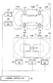
(Configuration of the entire horse racing game device)
The overall configuration of the horse racing game apparatus is shown in the block diagram of FIG.
The
[0019]
The
The
[0020]
A live
A
[0021]
A
[0022]
An
[0023]
The
[0024]
A large number of infrared
[0025]
An
[0026]
An
[0027]
A
[0028]
The
[0029]
A goal LED /
[0030]
The
[0031]
Various devices for maintaining the horse
A 10-
[0032]
A
[0033]
When the lifter operation SW 88 is operated, the entire course is moved up and down by the
To prevent danger, a buzzer is sounded to move the entire course up and down slowly. However, when moving the whole course downward, there is a risk of accidents such as pinching fingers, so move slowly, but when moving the whole course upward, there is less danger, so move it relatively quickly for maintenance. Time is being shortened. In addition, the UP / DOWN limit SW prevents danger caused by malfunction.
[0034]
(Horsefoot sound generator)
FIG. 3 shows the configuration of the horseshoe
The
In a conventional horse racing game device, instead of simply emitting horseshoe sounds from a plurality of speakers in order to represent the running sound of a horse, the volume of the plurality of speakers is adjusted to produce an effect as if a horse is circling around. It was. However, since it is only necessary to adjust the volume of a plurality of speakers, it has not been possible to change the sound effect according to the race development. For example, in a race development in which all horses run as one group, or in a race development where a small number of horses form the leading group and the remaining horses form the following group, a large number of horses form the leading group and one or Even in the race development where a small number of horses form the tail group, the same sound effect was always emitted.
[0035]
The
Twelve dome speakers SP <b> 1 to SP <b> 12 are arranged on the
[0036]
The twelve speakers SP1 to SP12 are provided with
Each of the 12
[0037]
When the game starts, various event signals are sent from the
When the race starts, the current position and horse number of the running horse are sent from the
[0038]
For example, if six horses from No. 1 to No. 6 are running and are racing as shown in FIG. 3 in the order of No. 1, No. 2, No. 3, No. 6, No. 5, No. 4, As shown in FIG. 4, the volume of each channel is determined.
As a horse racing game device, a race is performed based on a predetermined race development, and it is possible to generate a horseshoe sound according to the race development, but in this embodiment, the current position of the model horse is determined. A horseshoe sound is generated based on the detected position. Thereby, even if a specific model horse is delayed or stopped due to some accident, a horseshoe sound suitable for the current situation can be emitted.
[0039]
As shown in FIG. 4, the peaker SP1 outputs the footsteps of the sixth horse that has passed and the footsteps of the fifth horse that is approaching. The speaker SP2 outputs the footsteps of the second and third horses that have passed by and the footsteps of the sixth horse that passes in front of you. The speaker SP3 outputs the footsteps of the first horse that passed by, the footsteps of the second and third horses passing in front of the eyes, and the footsteps of the sixth horse approaching. The speaker SP4 outputs the footsteps of the first horse passing in front of the eyes and the footsteps of the second and third horses approaching. The speaker SP5 outputs the footstep sound of the first approaching horse. Horse footsteps are not output from the speakers SP6 and SP7. The speaker SP8 outputs the footsteps of the 4th horse that has passed. The speaker SP9 outputs the footsteps of the fourth horse that passes in front of the eyes and the footsteps of the fifth horse that passes by. The speaker SP10 outputs the footsteps of the fifth horse passing in front of the eyes and the footsteps of the fourth horse approaching. The speaker SP11 outputs the footsteps of the fifth horse approaching and the footsteps of the fourth horse approaching. The speaker SP12 outputs the footsteps of a distant 6th horse that has passed and the footsteps of a distant 5th horse approaching.
[0040]
FIG. 4 shows the volume of each channel in each speaker, but the overall volume is raised so that a certain amount of sound is output even in the blank channel.
Thus, according to the horseshoe sound generator of this embodiment, the footsteps of the horse can be faithfully reproduced according to the number of running horses and the race development, and the sense of movement, perspective, etc. of the sound image are dramatically improved. Realistic sound effects can be reproduced.
[0041]
(Position detector)
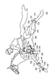
The configuration of the
The
In the horse racing game apparatus according to the present embodiment, as shown in FIG. 6, the
[0042]
Since the
As shown in FIG. 5, the X-direction
[0043]
On the other hand, the Y-direction
Since the X-direction
[0044]
In the present embodiment, this point is realized as shown in FIG. In the X-direction
[0045]
At the time of assembly, as shown in FIG. 6, the
At the time of disassembly, the
[0046]
Since the Y-direction
In this embodiment, the detection coil pitch in the X-direction
[0047]
Thus, according to the position detection unit of the present embodiment, the position detection plate can be divided, easily assembled, and disassembled even for a large truck that is difficult to form with a single position detection plate. This makes it possible to realize a large truck that can be competed by many model horses at once.
(Infrared output part)
The configuration of the
[0048]
In the present embodiment, an infrared signal is emitted from the
[0049]
For this reason, as shown in FIG. 7, a large number of infrared
[0050]
As shown in FIG. 8, the
As described above, according to the infrared output unit of the present embodiment, it is possible to reliably transmit an instruction signal by infrared rays regardless of where the carrier is located on the traveling track.
[0051]
(Shining turf)
The structure of the shining
In order to make it attractive as a horse racing game device, it is required to produce a powerful race. For this reason, the video is played during the race, the BGM is played, and the horseshoe sound described above is played. In the present embodiment, a more powerful race is realized by embedding a light emitter in the
[0052]
As the shining
As shown in FIG. 10, a
[0053]
The shining
Until the race starts, the
[0054]
When the race is started, the
When the race is over, the
[0055]
As described above, according to the shining turf of the present embodiment, a more powerful race can be realized by illuminating the track on which the model horse runs in addition to the image and the sound such as BGM and horse footsteps.
(Satellite (part 1))
The configuration of the
[0056]
FIG. 11 is a view of the
[0057]
A
[0058]
If the use of cash is permitted, the
In the case of playing a game using medals, medals may be inserted from the
[0059]
If the prediction is correct and the right to receive a payout is generated, the number of medals obtained is accumulated in the horse racing game apparatus. Bets can be placed using medals accumulated inside.
When the game is over and the acquired medal is to be received, the
[0060]
FIG. 12 is an example of a bet screen displayed on the 17-
[0061]
In real horse racing, you can look at the horse racing newspaper or see the state of the horse in the paddock, and write your own memos on the horse racing newspaper with a red pencil. Therefore, in the present embodiment, when the player traces the race information area at the top of the screen with his / her finger, the position is recognized by the touch panel so that the red line of the traced trajectory can be drawn. For example, as shown in FIG. The contents of the betting schedule, 1-2, 1-12, 2-12, etc. can be noted on the screen.
[0062]
Note that a memo using the touch panel is only allowed while the race information is displayed, and the memo is erased at the same time as the display image is changed.
As described above, according to the satellite of the present embodiment, an arbitrary memo can be drawn on the monitor screen, and realistic prediction can be made while writing the memo like a real horse race.
[0063]
(Satellite (part 2))
The configuration of the
In the above-described embodiment, the information on the current race is displayed on the 17-
[0064]
Therefore, in this embodiment, the
[0065]
Each
[0066]
Therefore, when it is desired to make a prediction by taking a sufficient amount of time, the 17-inch monitor is read by reading the successive race information stored in the
[0067]
As described above, according to the satellite of the present embodiment, the player can display the desired race information and bet, so that sufficient time can be taken to make a prediction carefully, or a prediction can be determined while talking with friends. can do. In addition, since the time between races may be the same as before and does not need to be particularly long, the operation efficiency of the horse racing game apparatus is not reduced.
[0068]
(Starting gate)
The configuration of the starting gate will be described with reference to FIGS. 15 and 16.
The starting gate of the present embodiment is configured to open at the start of the race, like a starting gate in real horse racing.
As shown in FIG. 15, the
[0069]
As shown in FIG. 16, each
When the rotation
[0070]
As shown in FIG. 15, as the
[0071]
The
When the twelve
[0072]
When the race starts, the rotating
Thus, according to the starting gate of this embodiment, a real horse racing game can be realized by opening the gate at the start of the race, like a real horse racing.
[0073]
(Model horse carriage and carrier)
The configuration of the model horse carriage and carrier will be described with reference to FIGS. 17 is a structural diagram of a model horse carriage and carrier, FIG. 18 (a) is a bottom view of the model horse carriage, FIG. 18 (b) is a plan view of the carrier, and FIG. 18 (c) is a cross section near the center of the carrier. FIG. 19 is a block diagram of the carrier.
[0074]
A
The
[0075]
As shown in FIG. 17, a traveling
[0076]
The
[0077]
A
A
[0078]
As shown in FIG. 18 (b), rotating
The rotating
[0079]
As illustrated in FIG. 18B, the
The
[0080]
As shown in FIG. 17 and FIG. 18C, the
As shown in FIG. 17, an infrared
[0081]
As shown in FIG. 17, an
FIG. 19 is a block diagram of a control system for controlling the
The
[0082]
The
The control signal to the
[0083]
The
[0084]
The
When the
[0085]
The
When the
[0086]
When the
[0087]
Regardless of whether or not the
[0088]
In this embodiment, a
First, by mounting the
[0089]
In the present embodiment, the infrared
[0090]
Further, by mounting the
[0091]
Further, by mounting the
[0092]
(Model horse and model jockey)
Details of the structure of the model horse and the model jockey will be described with reference to FIGS. The
[0093]
The structure of the
As shown in FIG. 20, a
[0094]
The
[0095]
The
[0096]
As shown in FIG. 21, a short
[0097]
Engagement pins 346 protrude from the rear surface of the
[0098]
Accordingly, when the
The positional relationship between the protruding
[0099]
Next, the structure of the
The
[0100]
A
Accordingly, the rotation of the driven
[0101]
The base end portion of the
[0102]
Further, the upper end of the
The lower end of the
[0103]
FIG. 24 is an exploded perspective view of the
[0104]
FIG. 22 shows a state when the
[0105]
At this time, the
[0106]
Thereafter, the same operation is repeated. That is, by continuously rotating the
Further, if the
[0107]
In this case, the
[0108]
The
In the state of FIG. 25, since the
[0109]
When the rotational direction of the
As described above, according to the model horse and the model jockey of this embodiment, by rotating one of the rotating magnets, the model horse repeatedly opens and closes and simulates the running of the horse. The movement of the jockey during running can be simulated in accordance with the opening and closing leg movements. Furthermore, a model jockey's whirling action and a winning pose can be simulated by rotating the other rotating magnet.
[0110]
(Horse racing game)
A horse racing game according to the first embodiment of the present invention will be described with reference to FIGS.
The horse racing game according to the present embodiment is configured such that various horse race combinations closer to real horse racing and odds like real horse racing are set by using the above-described horse racing game apparatus.
[0111]
The greatest feature of the horse racing game of this embodiment is that the popularity varies depending on the race result. In conventional horse racing games, the power relationship between horses is always the same, and even if a horse wins continuously, the odds are the same for the same opponent. However, in the horse racing game of the present embodiment, as in a real horse racing game, the more popular it is, the more popular it is, the more suitable the race is, the more popular it is. The factor is determined and the factor is set in detail. In addition, the prediction newspaper is not just a decoration for horse racing games, but can include predictions with a true persuasive power determined from various factors.
[0112]
(Registered horse composition)
The configuration of the registered horse will be described with reference to FIG.
In the present embodiment, 100 horses are registered internally and the horse data for 100 horses is held. The race will be held with 12 of them.
As shown in FIG. 26 (a), 100 horses have a pyramid structure divided into 3 types and 6 ranks in order of basic ability. Super GI class S class, GI class A class, GII class B class, GIII class C class, OP class D class, and conditional battle class E class. Conditionally, there are three types: S class and A class, B class, C class, D class, and E class.
[0113]
The basic ability value is unique to the horse and will not change no matter how popular it is. From a specific race, the top and bottom relationship between popularity and power changes depending on the situation, conditions, and conditions at that time, but in the long run it is an unchanging “difference in quality” and “difference in case”. .
Four horses are registered as S class. The S class is a super GI class having a basic ability value of 360 or more. Has a model horse dedicated to registered horses.
[0114]
Eight horses are registered as A class. The A class is a GI class having a basic ability value of 320 to 360. He is a regular horse for GI races and basically forms a low tension on the GI route. Participate only in heavy prize races (GI race, GII race, GIII race).
Twelve horses are registered as class B. Class B is class GII having a basic ability value of 240-320. With the GII and GIII races as a foothold, he is planning to win the GI race. Some horses are comparable to Class A if they are good distances.
[0115]
Sixteen horses are registered as C class. Class C is class GIII having basic ability values of 160-240. I am a mid-sized horse in the GII and GIII races. Run regardless of open race or heavy race.
20 horses are registered as D class. The D class is an OP class having a basic ability value of 80 to 160. Going back and forth between open race and GIII race. Run regardless of open race or heavy race.
[0116]
40 horses are registered as E class. The E class is a conditional battle class having a basic ability value of 80 or less. If you do not perform well in the open race, you will not be able to run into the heavy prize. Horses with poor results are forced to rest. Half of the 40 are 20 and are not grazed. In addition, E class horses are forced to graze if the race results are poor, and substitute horses enter.
[0117]
Since 20 E-class horses are not included in the rotation, the rotation is performed with 80 horses even in a maximum state where there is no broken horse due to a fracture or the like. Since it has 12 heads, it will run once every 6-7 races on average (80 ÷ 12 = 6.66). E-class horses run once in an average of 13 races.
As described above, according to the configuration of the registered horse of the present embodiment, the registered horse is divided into a plurality of ranks according to the basic ability value, and the race to be started is determined based on the rank, so it is as diverse as a real horse race. Can form a true race.
[0118]
(Stable system)
The stable system of this embodiment is demonstrated using FIG.
As described above, in the present embodiment, 100 horses are registered internally, and these 100 horses have a pyramid configuration divided into six ranks in the order of basic ability. In this embodiment, 100 horses are divided into groups that simulate a stable, and each horse belongs to a specific stable. For example, as shown in FIG. 27, 100 horses are distributed from A stable to 12 stables called L stable.
[0119]
Each stable will have features such as how to set the rotation and the choice of the race you want to start.
Depending on the stable, if it is in good condition, it will have a personality such as a stable that tries to run continuously, or a stable that observes rotation. This will affect the race where you want to start.
[0120]
In addition, depending on the stables, the stables are used for intense Spartan training, and the stables are used for careful training. Strongly affects training parameters.
In addition, there are stables for selecting a bullish start race, stables for selecting a solid start race, and stables for selecting a start race with an emphasis on distance suitability. Affects the desired rank.
[0121]
As described above, according to the present embodiment, by assigning the registered horses to a plurality of stables and giving the characteristics to each stable, the desired race, the desired rank, the horse parameters, etc. are affected. A variety of races that take into account factors can be organized.
(Race composition)
The race configuration of this embodiment will be described with reference to FIG.
[0122]
In the present embodiment, a race configuration simulating a real horse racing is performed. The race configuration is composed of a total of 36 races of 18 races in the first half and 18 races in the second half, and these 36 races are repeated. The first half race assumes a real horse racing spring race, and the second half race assumes a real horse racing autumn race.
The distances and grades for all 36 races are as shown in FIG. For example, the first race is a medium-distance GIII race, the second race is a long-distance OP race, the third race is a medium-distance GIII race, and as shown in FIG. 28 (a) below. All 36 races are organized in order. The long-distance GII race is only in the first half, and the short-distance GII race is only in the second half.
[0123]
The 18th and 36th races are races based on popularity votes. A real horse racing Takarazuka Memorial Race and Arima Memorial Race are assumed. The starting horse is determined based on the number of bets made by the player. For example, the top 8 players with the highest number of bets in the past 18 races will run. Select the remaining 4 frames in the usual way.
These 36 races are repeated.
[0124]
The 36 race-by-distance configurations are 6 long-distance races, 24 medium-distance races, and 6 short-distance races. The grades of all 36 races are 6 GI races, 8 GII races, 10 GIII races, and 12 OP races.
As described above, according to the present embodiment, since it is a varied and varied race configuration simulating a real horse racing race configuration, it does not get tired even if it is played for a long time, compared with a real horse racing race. You can enjoy it.
[0125]
(Horse ability value)
The ability value of the horse according to this embodiment will be described with reference to FIGS.
In conventional horse racing games, odds are determined only by horse-specific ability values. The ability values were the same regardless of the results and short reviews of the previous run, and as a result, the odds were the same for the same combination.
[0126]
In the present embodiment, the popularity of horses is not only based on the ability value, but the popularity varies depending on the situation. In particular, it places importance on the fact that popularity varies with distance and popularity varies with recent results.
In the present embodiment, a core factor for determining horse popularity and lottery ability is set as a main factor, and an element is set as a sub-factor to give a plus alpha bonus to the main factor.
[0127]
(Main factor)
Main factors include basic ability values and fulfillment values.
The basic ability value is a value for performing an absolute rating of the horse, and is a quality inherent to the horse. Basically, there is a high probability that a horse with a high basic ability value will be active. The basic ability value is individually given for each long distance, medium distance, and short distance.
[0128]
A specific example of the basic ability value is shown in FIG.
The first horse in FIG. 29 has a long-distance basic ability value of 380, a medium-distance basic ability value of 300, and a short-distance basic ability value of 220. The first horse is a long-distance horse whose basic ability value for long-distance is higher than other distances.
The second horse in FIG. 29 has a long-distance basic ability value of 200, a medium-distance basic ability value of 260, and a short-distance basic ability value of 320. The second horse is a short-distance horse whose basic ability value for short-distance is higher than other distances.
[0129]
The third horse in FIG. 29 has a long-distance basic ability value of 80, a medium-distance basic ability value of 120, and a short-distance basic ability value of 70. Horse No. 3 is a medium-distance horse whose basic ability value at medium distance is higher than other distances.
The fourth horse in FIG. 29 has a long-distance basic ability value of 190, a medium-distance basic ability value of 200, and a short-distance basic ability value of 190. Horse No. 4 is a universal field where the basic ability values are averaged regardless of the distance.
[0130]
In the race configuration, since the middle distance race is the main, the basic ability classes shown in FIG. 26 are ranked according to the height of the medium ability basic ability value. Horses with a medium distance basic ability value of 360 or more are designated as S class, horses with a medium distance basic ability value within the range of 320 to 360 are designated as A class, and horses with a medium distance basic ability value of 240 to 320 are designated as the A class. B class, horses with a medium distance basic ability value in the range of 160 to 240 are set as C rank, horses with a medium distance basic ability value in the range of 80 to 160 are set as D class, and a medium distance basic ability value is 80. The following horses are E class.
[0131]
The fulfillment value is a value determined so that the more you win, the more popular it becomes. It is determined based on the result of the near run (for example, the previous 4 runs). The point is high so that the content of the near run is good. Predetermined points are determined for the order of arrival for each race grade. The point is set so that the higher the order of arrival, the higher the point, and the higher the race grade, the higher the point.
[0132]
A specific example of the point distribution is shown in FIG.
In the OP race,
[0133]
In the case of the GIII race, the plus point is twice that of the OP race, and the minus point is the same as the OP race. 20 points for 1st place, 12 points for 2nd place, 8 points for 3rd place, 4 points for 4th place, 2 points for 5th place, 0 points for 6th place, -1 point for 7th place, -2 points for 8th place, -9 points are awarded for 9th place, -4 points for 10th place, -5 points for 11th place, and -6 points for 12th place.
[0134]
In the case of the GII race, the plus point is four times the OP race, and the minus point is the same as the OP race.
[0135]
In the case of the GI race, the plus point is eight times the OP race, and the minus point is the same as the OP race. 80 points in 1st place, 48 points in 2nd place, 32 points in 3rd place, 16 points in 4th place, 8 points in 5th place, 0 points in 6th place, -1 point in 7th place, -2 points in 8th place, -9 points are awarded for 9th place, -4 points for 10th place, -5 points for 11th place, and -6 points for 12th place.
[0136]
The fulfillment value R is determined by the following equation, for example, from the points of the previous four runs.
R = a4 × 2 + a3 × 3 + a2 × 4 + a1 × 5
However, a4: Points before 4th run
a3: Points before the third run
a2: Points before the second run
a1: Points before 1 run
As a result of the calculation, when the enrichment value R becomes negative, it is forcibly set to zero.
[0137]
(Sub factor)
As sub-factors, there are the degree of increase, Baba aptitude, distance aptitude, deployment aptitude, and training level. As shown in FIG. 31, five levels are evaluated for each sub-factor.
The degree of increase is a sub-factor that indicates whether the horse is in increasing condition. Evaluate from the results of the close-
[0138]
Distance suitability is a sub-factor that indicates whether distance is suitable. Evaluation is based on the distance of this race and a comparison of the basic ability values for the distance of the horse. If you are good at the distance of this race, you will get 4 points, if you are slightly good, you will be 3 points, if you are not good, you will be 2 points, if you are not good, you will be 1 point, if you are not good, you will be 0 points.
[0139]
Baba suitability is a sub-factor that indicates whether or not the dressing state is suitable. This will be evaluated by comparing the race condition of this race with the suitability of that horse. If there is no problem with the racetrack status of this race, the score is 4 points. If there is no problem, the score is 3 points. If there is a slight problem, the score is 2 points.
[0140]
The degree of training is a sub-factor that indicates whether the current condition is good. Evaluation is based on changes in rotation and tone. Depends on the stable you belong to. If the recent physical condition is in good condition, it will be 4 points, if it is in good condition, it will be 3 points, if it is a parallel line, it will be 2 points, if it is not good, it will be 1 point, and if it is bad, it will be 0 point.
[0141]
The development characteristics are sub-factors that indicate whether the race development and pace are beneficial. We will evaluate the pace expected from the running members of this race and the leg quality inherent to the horse. 4 points if the development expected in this race is advantageous, 3 points if slightly advantageous, 2 points if normal, 1 point if slightly disadvantaged, 0 points if disadvantaged To do.
[0142]
The sub-factor is an element that may affect the lottery. Regardless of whether or not it affects the lottery result, the odds are affected by the “expected expected value”. From the race results, some common elements are often included in the upper horses. From the top horses of the race results, for example, it is possible to make an analogy that this race was decided by horses that are good at heavy race.
[0143]
(Flow of horse racing game)
The horse racing game according to this embodiment will be described with reference to the flowchart of FIG.
(Determination of distance and grade for next race)
First, according to the race configuration described above, the distance and grade (GI, GII, GIII, OP) of the next race are determined (step S10).
[0144]
(Fullness calculation)
Next, for all the registered horses, the degree of fulfillment of the next race is recalculated from the results of the previous four runs (step S11). Based on the above-described solid value table and the results of the previous four runs, the calculation is performed from the above-described solid value formula.
(Determination of desired rank for starting)
Next, a desired starting rank is determined from the basic ability value and the recalculated degree of fulfillment (step S12).
[0145]
Details of the method of determining the desired rank for starting will be described.
In this embodiment, a desired registration system is adopted. Each horse chooses a race to run based on its basic ability and fulfillment level. In principle, the desired horse is given priority. However, in the present embodiment, unlike the real horse racing, the number of running horses is fixed at twelve, so when there is a lot of hope, it is turned to another race, and when there is little hope, another race is brought from the desired horse to twelve. There is a need. In order to make the adjustment smoothly, a desired rank for each horse is determined and updated after the race.
[0146]
Four ranks are set as the desired starting rank. Rank A is a “I want to start” rank, Rank B is a “can start” rank, Rank C is a “I do n’t want to start” rank, and Rank D is “not eligible to start” ) ”Rank. The four ranks are assigned to a total of 12 cases according to four grades and three distances.
[0147]
A method for calculating the desired starting rank will be described.
First, after the race, the full value is recalculated for each horse.
Next, for each horse, the desired rank for the intermediate distance is determined from the value obtained by adding the basic ability value and the enrichment value for the intermediate distance. If this value is large, the desired rank will be higher, but the method for determining the desired rank will differ depending on the stable to which each horse belongs. For example, even for the same value, a horse belonging to a bullish stable gives a higher rank to races that are more powerful, but a horse belonging to a bearish stable gives a lower rank. As a result, there are horses that dare to challenge a high-class race, and there are horses that aim to step up step by step steadily, and can simulate the same situation as a real horse race.
[0148]
Next, based on the desired rank of the medium distance, the desired rank of the long distance and the short distance is determined in consideration of the distance suitability. That is, when the distance suitability is low, the rank is lowered as compared with the middle distance. However, rank C does not change. When the distance suitability is high, the rank is lowered for a grade higher than the basic rank, and it is left as it is for a lower grade. In this case as well, the judgment as to whether the distance suitability is high or low differs depending on the stables to which it belongs.
[0149]
For example, in the case of a B-class (GII class) horse shown in FIG. 33, the medium-distance GII race is rank A, the GI race is rank B, the GIII race is rank B, and the OP race is rank C. If long distance is suitable, medium distance is normal, and short distance is unsuitable, long distance GI race, GII race is rank A, GIII race is rank B, The OP race will be rank C. In the case of inappropriate short distances, the GI and GIII races are ranked C, the GIII races are ranked B, and the OP races are ranked C.
[0150]
The rank D is given in the following cases. For example, if a horse with a basic ability of E class cannot play an active part in the OP race, it will be all rank D except for the OP race. Also, horses with basic abilities of S class and A class are always ranked D in OP races.
As described above, in this embodiment, ranking at a medium distance is fundamental. FIG. 34 shows the middle distance rank classification according to the basic ability class.
[0151]
In the case of a horse of the super GI class (basic ability value + enrichment value: N1), the GI race is rank A, the GII race is rank C, the GIII race is rank C, and the OP race is rank C.
For horses of GI class (basic ability value + fulfillment value: N2 to N1), the GI race is rank A, the GII race is rank B, the GIII race is rank C, and the OP race is rank C.
[0152]
In the case of a quasi-GI class (basic ability value + fulfillment value: N3 to N2), the GI race is rank A, the GII race is rank A, the GIII race is rank B, and the OP race is rank C.
For horses of class GII (basic ability value + fulfillment value: N4 to N3), the GI race is rank B, the GII race is rank A, the GIII race is rank B, and the OP race is rank C.
[0153]
For horses of the GII and GIII class (basic ability value + fulfillment value: N5 to N4), the GI race is rank B, the GII race is rank A, the GIII race is rank A, and the OP race is rank B.
For horses of class GIII (basic ability value + fulfillment value: N6 to N5), the GI race is rank C, the GII race is rank B, the GIII race is rank A, and the OP race is rank B.
[0154]
In the case of a horse of GIII, OP class (basic ability value + fulfillment value: N7 to N6), the GI race is rank C, the GII race is rank B, the GIII race is rank A, and the OP race is rank A.
For horses of the OP class (basic ability value + fulfillment value: N8 to N7), the GI race is rank C, the GII race is rank C, the GIII race is rank B, and the OP race is rank A.
[0155]
If the basic ability is an E-class horse (semi-OP class (basic ability value + fulfillment value: N9 to N8)), only the OP race will be in rank A until the right to run a heavy prize, and the GI, GII, and GIII races Rank D.
Horses with basic abilities of S class and A class are always ranked D in the OP race.
(Decision of desired race)
Next, returning to FIG. 32, a desired race is determined based on the desired rank for each horse determined in this way (step S13).
[0156]
(Decision of race horse)
Next, the starting horse of the race is determined based on the desired starting race of each horse (step S14).
A method for determining a race horse will be described with reference to the flowchart of FIG.
[0157]
First, the number of horses desired to run in this race is counted (step S30). If the desired number of races in the race is 13 or more (step S31), 12 are selected by lottery (step S32). The horse that has been elected wants another race (step S33), and the starting horse for this race is determined (step S34).
[0158]
If the desired number of races in the race is exactly 12 (step S35), the race horses in the race are determined as they are (step S34).
If the number of horses desired to run in this race is 11 or less and less than 12 (step S36), the number of horses of the desired rank A is counted as the horses that want to start in the next race under the conditions of this race (step S37). If there is a deficiency (step S38), the deficiency is replenished (step S39), and the starting horse for this race is determined (step S34). If there is more than the shortage (step S40), the shortage is determined by lottery and supplemented (step S41), and the race horse for this race is determined (step S34).
[0159]
If there are fewer horses with the desired rank A in the race conditions of the next race than the shortage (step S42), the number of horses that want to run in the next race is counted for the time being. Step S44)
If there are 13 or more horses that want to run in the next race (step S45), the number of horses with the desired rank B is counted among the horses that want to start the next race under the conditions of this race (step S46). If there is a deficiency (step S47), the deficiency is replenished (step S48), and the starting horse for this race is determined (step S34). If there is more than the shortage (step S49), the shortage is determined by lottery and supplemented (step S50), and the race horse for this race is determined (step S34).
[0160]
If there are fewer horses with the desired rank B in the race conditions than the shortage in the next race (step S53), the amount is supplemented for the time being, and the process proceeds to step S53.
If the number of horses desired to start the next race counted in step S44 is 12 or less (step S54), the process proceeds to step S53.
[0161]
In step S53, the number of horses of desired rank A is counted among the horses that wish to start running one after another under the conditions of this race. Thereafter, the processing after step S38 is performed (step S55), and the running horse of this race is determined (step S34).
(Popularity vote)
Explain how to determine a running horse by popularity voting.
[0162]
Assuming the real horse racing Takarazuka Memorial Race and Arima Memorial Race, the 18th and 36th races will be races based on popularity voting. The starting place for the popular voting race is determined based on the number of bets placed by the player. The number of bets is 1 point when there is a single win, 0.5 points when there is a horse bet, and 0.25 points when there is a frame bet.
[0163]
For example, the top 12 heads with the most bets in the past 18 races will run. When the number of points is the same, the starting horse is determined according to the starting rank.
In addition, eight out of twelve horses may be selected by popularity voting, and the remaining four frames may be selected by a normal method.
Since there is a popular voting race, it is possible to start a specific horse in the popular voting race at the player's will by betting more on the horses that they like.
[0164]
(Odds decision)
Next, odds are determined based on the main factor and sub-factor of the horse running in the next race (step S15).
The odds calculation method will be described with reference to FIG. The odds include the basic factor's basic ability value, fulfillment level, sub-factor rise, distance suitability, dressing suitability, deployment suitability,
The main factor value M is the following equation, where B is the basic ability value at the grade and distance of this race, and R is the fulfillment value.
M = B + R
It is expressed.
[0165]
The odds sub-factor rate PO is expressed as follows: S1 is the point of increase, S2 is the point of distance aptitude, S3 is the point of Baba aptitude, S4 is the point of deployment aptitude, and S5 is the training point.
PO = (S1 + S2 + S3 + S4 + S5) × 5
It is expressed.
[0166]
The odds correction ability value AO is given by
AO = M + (M × PO / 100)
It is expressed.
The odds correction ability value AO is calculated for all horses running, and the odds correction ability values AO1, AO2,..., AO12 of each horse are obtained. The odds are calculated using these odds correction ability values. In this embodiment, the winning odds of one horse and the odds WW1-2 of the frame series 1-2 in the case of dividing 12 frames into 6 frames of 2 each are calculated.
[0167]
For example, the winning odds W1 for one horse is
W1 = (SAO / AO1) × (payout rate)
However, the sum of the odds correction ability values SAO = AO1 + AO2 + ... + AO12
It becomes.
Also, odds WU1-2 for Maren 1-2 is
[0168]
Also, the odds WW1-2 of the frame sequence 1-2 when dividing the 12 frames into 6 frames of 2 each is calculated in the same manner.
(Forecast decision)
Next, an anticipation person determines an anticipation based on the main factor and subfactor of the horse which will run in the next race (step S16).
[0169]
A prediction method by a predictor will be described with reference to FIG. The subfactors to be emphasized differ depending on the anticipator. A prediction is made using the corrected ability value thus determined, and a prediction mark is attached.
The
AOY1 = M + {M × ((S1) × K1) / 100}
It is expressed. However, K1 is a constant.
[0170]
The predicted ability value AOY1 for the
The
AOY2 = M + {M × ((S2 + S3) × K2) / 100}
It is expressed. However, K2 is a constant.
[0171]
The predicted
The
AOY3 = M + {M × ((S4) × K3) / 100}
It is expressed. However, K3 is a constant.
[0172]
The predicted
The
AOY4 = M + {M × ((S5) × K4) / 100}
It is expressed. However, K4 is a constant.
[0173]
The predicted
Note that the features of the
[0174]
(Lottery → winning horse and ranking)
Next, a lottery is performed based on the main factor and sub-factors of the horses running in the race to determine the winning horse and the ranking (step S17). The number, type, and degree of influence of the affected sub-factors are changed by random numbers, and a lottery is performed based on the correction ability value based on the random numbers, and the first and second winning horses and the ranking of all 12 horses are determined.
[0175]
As with the odds, the main factor value M is as follows:
M = B + R
It is expressed.
The subfactor value SLOT for the lottery shows the influence degree of the point S1 of the increase degree P1, the influence degree of the point S2 of the distance suitability P2, the influence degree of the point S3 of the dressing suitability P3, and the influence degree of the point S4 of the deployment suitability If the degree of influence of P4 and training point S5 is P5, it is obtained as a function of these values.
[0176]
The lottery correction capability value LOT is obtained as a function of the main factor value M and the lottery sub-factor value SLOT described above.
The lottery correction ability value LOT is calculated for all the horses running, and the lottery correction ability values LOT1, LOT2,..., LOT12 of each horse are obtained. An example of the lottery correction ability value is shown in FIG.
[0177]
A lottery is performed based on these correction ability values for lottery.
(Race development decision)
Next, when the winning horse and the order are determined, the race development is determined based on the result (step S18). In the conventional horse racing game, when the rank is determined, the horses run at the pace of each horse so that the determined rank is obtained. In the present embodiment, the race development is determined not only by the determined rank but also by taking into account factors such as the winning horse's leg quality, the combination of the running horse, the distance, and the racetrack state.
[0178]
A specific example of the race development determination method will be described.
There are race tables for 12 horses. The race table is a table that stores data on elapsed time and travel distance. For each horse, data on the distance traveled at predetermined time intervals is stored.
First, copy the contents of the distance table to the race tables of all horses. The distance table stores data on elapsed time and travel distance according to the race distance. At this stage, all racehorse race tables are the same.
[0179]
Next, the pace of the race is determined based on the overall quality of the racehorse and the order of arrival determined by lottery.
Next, the race table of each running horse is corrected based on the determined pace. For example, as a result of the lottery, when the runaway horse is first, the race table of each running horse is corrected so as to develop the race at a slow pace. Further, in the case of a race with many preceding horses, the race table of each running horse is corrected so as to develop the race at a high pace.
[0180]
Next, the race table is corrected in consideration of the unique distance characteristics and leg quality of each running horse. The race table is further corrected in consideration of other factors of each race horse, for example, the suitability, condition, etc. and the order of arrival.
Next, it is verified whether or not the corrected race table of each running horse does not exceed the maximum speed of the carrier.
[0181]
The individual running time is calculated from the race table of each starting horse thus determined. The position of each horse per unit time (for example, 0.5 seconds) and the forward direction are calculated from the race table, and the position of each horse is simulated. As a result, if there is a collision, the race data is corrected so that the carrier does not collide, for example, by adding a movement in an obliquely traveling direction, and the completion is made.
[0182]
(Bet acceptance ends)
Next, when a predetermined time has elapsed from the start of betting, the betting end time is approaching, and after a certain time has elapsed, betting acceptance is terminated (step S19).
(Race execution)
Next, a race is executed according to the race table of each running horse (step S20). During the race, live announcements will be made, horseshoe sounds will be produced, and the effects of shining turf will be added. The live announcement, horseshoe sound, and shining turf may be driven and controlled based on the race table that has already been determined. However, in this embodiment, the live announcement, horseshoe sound, and shining turf are based on the current detection position of the model horse. The drive is controlled. Even if the running condition of the model horse fluctuates due to an unexpected accident, it can be dealt with.
[0183]
(Data update)
Next, the data of each running horse is updated based on the actual race result (step S21). In the present embodiment, the data is updated based on the actual race result, not the lottery result. For example, even when a specific horse cannot travel as planned due to a trouble in the apparatus and the traveling result is different from the lottery result, the data is updated based on the actual traveling result.
[0184]
(Refund)
Next, based on the actual race result, the player is paid out according to the odds (step S22). In this embodiment, even in the case of a refund, the refund is performed based on the actual traveling result.
(Reproduce the past race)
In order to enhance the atmosphere before the race and provide a more realistic sensation, a race performed in the past is reproduced using a
[0185]
As the race to be reproduced, it is desirable that the bet is used as a reference by the player and the atmosphere before the race is enhanced.
For example, if there is one horse in the previous run during the race start horse, the previous race related to that horse is reproduced. The player can use it as a reference for betting.
In addition, if a horse with high odds is reproduced during the race, the race when the horse gets good results, or if there are multiple horses with high odds that have played in the past , To reproduce the race at that time. You can increase your expectation for horses with high odds and increase the degree of coin collection.
[0186]
In the case of a heavy race, the previous heavy race is reproduced. You can raise your expectations for the heavy race.
In the reproduction of the race, not only the race pattern is reproduced using the
[0187]
[Second Embodiment]
(Horse racing game device)
A horse racing game apparatus according to a second embodiment of the present invention will be described with reference to FIGS. The same or similar components as those of the horse racing game apparatus according to the first embodiment described above are denoted by the same reference numerals, and description thereof is omitted or simplified.
[0188]
(External appearance of horse racing game device)
The overall appearance of the horse racing game apparatus is shown in FIG.
In the center of the horse
[0189]
A 10-
On one side of the short side of the
[0190]
Above the
(Configuration of the entire horse racing game device)
The overall configuration of the horse racing game apparatus is shown in the block diagram of FIG.
[0191]
In place of the shining
The track
[0192]
(Track lighting section (1))
The configuration of the
The
[0193]
For the
[0194]
In addition, a large number of
An example of illumination control by the
[0195]
Until the race starts, the player is urged to participate and lights up to produce the betting time before the race starts. For example, the turf-colored
[0196]
When the
When the race starts, the track
[0197]
When the race is over, it will be illuminated to produce the excitement of the race results. For example, the
[0198]
As described above, according to the track illumination unit of the present embodiment, in addition to video, audio such as BGM and horse footsteps, the entire track on which the model horse runs is lit, or the spot on the running model horse is spotted. As a result, a more powerful race can be realized.
(Track lighting part (2))
Another specific example of the
[0199]
In this specific example, the
A
[0200]
An example of illumination control in the
Until the race starts, the player is urged to participate and lights up to produce the betting time before the race starts. For example, the tip of the
When the race starts, the track
[0201]
When the race is over, it will be illuminated to produce the excitement of the race results. For example, while rotating the
[0202]
As described above, according to the track illumination unit of this specific example, in addition to the image and the sound such as BGM and horse footsteps, a more powerful race is realized by spotting the running model horse. be able to.
(Track lighting part (part 3))
Still another specific example of the track lighting unit of the horse
[0203]
In this specific example,
The light from the
[0204]
According to the track lighting unit of this specific example, in addition to video, audio such as BGM and horseshoe sounds, the color of the track can be freely changed as the race of the horse racing game progresses, and a powerful race can be performed. Can be realized.
In addition, although the track illumination part of this example may be used independently, it is more effective when used in combination with the track illumination part (part 1) or the track illumination part (part 2) described above.
[0205]
(satellite)
The
[0206]
In the
[0207]
The internal configuration of the
[0208]
The
DC power is supplied from the DC connector 530. The DC connector 530 is connected to the
[0209]
The
The
[0210]
When turning off the
[0211]
Therefore, in this embodiment, the
[0212]
In the present embodiment, this is utilized, and when the door is opened and the
[0213]
Instead of providing the
In the
[0214]
The structure of the
[0215]
The player places his
In this way, in this embodiment, a power source is not provided for each satellite, but a single power source is provided for a plurality of satellites. Therefore, the installation space can be reduced, and costs can be saved. In addition, according to the present embodiment, the door switch is provided and the power shut-off process is started when the door switch is turned off. Therefore, the environment setting at the time of power shut-off can be saved, data can be saved, etc. At the time of start-up, it is possible to return to the state before power-off. Further, since the medal cup holder is provided at the medal payout opening on the front panel, it is possible to place an obstructive medal cup during the game and to automatically receive the payout medal.
[0216]
In addition, although this embodiment demonstrated as an example the satellite of a competitive game device, game devices other than a competitive game device, for example, the game device which performs a bingo game, a blackjack game, etc. in which a some player participates and plays a game, etc. The present invention may be applied to satellites.
(Horse racing game)
A horse racing game according to the second embodiment of the present invention will be described with reference to FIGS.
[0217]
The horse racing game according to the present embodiment uses the above-described horse racing game device and devise the video before the start of the race to pursue the fun of predicting the arrival order and make it easy to predict.
The flow of the horse racing game of this embodiment will be described along the time chart of FIG. A case where one race is performed in two minutes will be described.
[0218]
As a whole flow, a bet time is 0 second to 45 seconds of one race time, a race time is 45 seconds to 100 seconds, and a final time is 100 seconds to 120 seconds. The gate-in time is between 40 seconds and 45 seconds.
The
[0219]
For 25 to 40 seconds after the introduction of all the running horses by paddock video is completed, the
[0220]
The
As the sound, the live
[0221]
The mechanism of the
The
[0222]
In the above embodiment, various information introduction videos are displayed on the
Next, a specific example of the paddock video display method will be described with reference to FIGS. FIG. 50 is a flowchart of a paddock video display method according to this specific example, and FIG. 51 is a diagram showing a paddock video probability table.
[0223]
In the present embodiment, an image reflecting the ability, temper, current physical condition, etc. of the running horse is generated. A plurality of types of images representing various horse motions are set as unit images, and these unit images are combined based on the parameters described above to generate a paddock image.
In this specific example, a paddock video generation method based on the temperament parameter of a running horse will be described.
[0224]
As unit images representing the motion of the horse, as shown in FIG. 51, 8 types are set as the overall motion and 3 types are set as the tail motion. Eight types of overall operations are classified into two categories. The first category of the overall movement is related to the action of raising the head, "raising the neck", "the same (raising the neck) sideways", "the same (raising the neck)" and "swinging the same (raising the neck)" 4 motion images are included. The second category of the overall movement relates to the movement of stroking the neck, “nodding the neck”, “swinging the neck”, “stopping the head”, “stopping the neck”, “swinging the head” Four actions are included: “Raise the neck from”. The tail movement includes three actions of “hanging”, “shaking”, and “shaking” the tail.
[0225]
The paddock video display method of this embodiment selects and displays these motion videos according to the probability shown in FIG. In the table of FIG. 51, the probability that the motion image is selected changes according to the temper of the horse. A tempered horse has a higher probability of a specific motion image, for example, a quiet motion image, and a lower probability of other motion images. If the probability of a specific motion image increases, the same motion is likely to be selected, and the motion change is reduced. For horses with rough temper, the same probability is set for all motion images except for a quiet motion image (for example, the head is raised with the neck raised and stopped with the neck abandoned). Different actions are likely to be selected, resulting in restless movements.
[0226]
Next, a paddock video generation method will be described with reference to the flowchart of FIG.
Initially, one operation is selected from eight operations including the first category and the second category for the entire operation, and one operation is selected from three operations for the tail operation (step S100). 50 is selected according to the probability of the table in FIG. 50 according to the temper of the horse. Next, the selected operation is displayed on the large projector 24 (step S101).
[0227]
Next, it is determined whether the lottery result of the entire operation relates to the first category or the second category (step S102). Regarding the first category, the next operation is an operation to be selected from the first category so that the operation is smooth. Specifically, the first category “raise the neck”, “the same (raise the neck) sideways”, “the same (raise the neck) stop”, and the second category “the same (raise the neck)” The four actions are “raise the head from the beginning”. Regarding the second category, the next operation is an operation to be selected from the second category so that the operation is smooth. Specifically, in the first category, “swing from the head (raising the neck)”, in the second category, “swinging the neck,” “same (swinging the neck) sideways” “same (swinging the neck) ) Stop ”.
[0228]
If the lottery result of the overall motion is related to the first category, in step S103, one motion is selected from the four motions belonging to the first category for the overall motion, and one motion is selected from the three motions for the tail motion. Is done. 50 is selected according to the probability of the table in FIG. 50 according to the temper of the horse. Next, the selected operation is displayed on the large projector 24 (step S104).
[0229]
Next, it is determined whether or not the display time of the paddock video has ended (step S105), and if the display time has ended, the display ends immediately. If the display time has not expired, steps S103 to S106 are executed until the lottery result of the entire operation becomes the “swing from the head (raise the head)” operation, and the operations in the first category are continuously selected. . If it is determined that the lottery result of the overall motion is “swing from the head (raising the head)”, the process proceeds to step S107.
[0230]
If the lottery result of the overall action is an action related to the second category, in step S10, one action is selected from the four actions belonging to the second category for the overall action, and one action is selected from the three actions for the tail action. A lottery will be held. 50 is selected according to the probability of the table in FIG. 50 according to the temper of the horse. Next, the selected operation is displayed on the large projector 24 (step S108).
[0231]
Next, it is determined whether or not the display time of the paddock video has ended (step S109), and if the display time has ended, the display ends immediately. If the display time has not expired, steps S107 to S110 are executed until the lottery result of the entire operation becomes “swing from the head (swing your head)” to select the operation in the second category. Continue to be. If it is determined that the lottery result of the overall motion is “swing the head from the same (nagging the neck)”, the process moves to step S103.
In this way, since the overall movement is divided into two categories and the movement is selected within the category, the horse can perform a natural movement, and the temperament can be distinguished by looking at the movement.
[0232]
In the above description, the lottery is always performed according to the table of FIG. 51 corresponding to the temper of the horse. However, in order to confuse the prediction by the player, the probability that is contrary to and / or does not depend on the probability of the table of FIG. You may make a lottery by. The degree of difficulty of prediction can be adjusted by changing the value of this probability and the number of lotteries.
[Modified Embodiment]
The present invention is not limited to the above embodiment, and various modifications can be made.
[0233]
For example, in the above embodiment, the present invention is applied to a horse racing game. However, the present invention can also be applied to a racing game other than horse racing, a car racing, an auto racing, and the like.
In the above embodiment, the present invention is applied to a competitive game in which a model traveling body is actually run. However, the above-described competitive game method may be applied to a competitive game using a home game. The program for realizing the competitive game method may be provided by a storage medium such as a CD-ROM or a game cartridge, or may be provided via a communication line.
[0234]
【The invention's effect】
As described above, according to the present invention, a competitive game method that enables various combinations of races, and that popularity varies according to the race results, further pursuing the fun of predicting the order of arrival and the fun of race development. Can be realized.
[Brief description of the drawings]
FIG. 1 is an external view of an entire horse racing game apparatus according to a first embodiment of the present invention.
FIG. 2 is a block diagram showing a configuration of the entire horse racing game apparatus according to the first embodiment of the present invention.
FIG. 3 is a diagram showing a configuration of a horseshoe sound generating unit of the horse racing game apparatus.
FIG. 4 is a diagram showing a specific example of sound volume of a sound source in each speaker of a horseshoe sound generating unit.
FIG. 5 is a diagram showing a configuration of a position detection unit of a horse racing game apparatus.
FIG. 6 is a cross-sectional view for explaining a position detection unit of the horse racing game apparatus.
FIG. 7 is a diagram showing a configuration of an infrared output unit of the horse racing game apparatus.
FIG. 8 is a cross-sectional view for explaining an infrared output unit of the horse racing game apparatus.
FIG. 9 is a diagram showing a configuration of a shining turf of a horse racing game apparatus.
FIG. 10 is a cross-sectional view for explaining the shining grass of the horse racing game apparatus.
FIG. 11 is a view of the satellite of the horse racing game apparatus as viewed from above.
FIG. 12 is a diagram showing an example of a game screen displayed on the satellite of the horse racing game apparatus.
FIG. 13 is a diagram showing another example of the game screen displayed by the satellite of the horse racing game apparatus.
FIG. 14 is a block diagram showing a satellite configuration of the horse racing game apparatus.
FIG. 15 is a diagram showing a configuration of a start gate of a horse racing game apparatus.
FIG. 16 is a perspective view for explaining the operation of the start gate of the horse racing game apparatus.
FIG. 17 is a cross-sectional view showing the structure of a model horse carriage and carrier of a horse racing game apparatus.
18 is a view showing the structure of a model horse carriage and carrier of the horse racing game apparatus, FIG. 18 (a) is a bottom view of the model horse carriage, FIG. 18 (b) is a plan view of the carrier, and FIG. c) is a sectional view of the vicinity of the center of the carrier.
FIG. 19 is a block diagram of a carrier of a horse racing game apparatus.
FIG. 20 is a diagram showing a structure of a model horse of a horse racing game apparatus.
FIG. 21 is a perspective view for explaining a partial mechanism of the model horse.
FIG. 22 is a diagram showing a structure of a model horse of a horse racing game apparatus, in a state when a model jockey swings up a whip.
FIG. 23 is a perspective view for explaining a partial mechanism of the model horse.
FIG. 24 is a perspective view for explaining a partial mechanism of the model horse.
FIG. 25 is a diagram showing a structure of a model horse of a horse racing game apparatus and a structure when a model jockey stands up.
FIG. 26 is an explanatory diagram of a configuration of a registered horse in the horse racing game according to the first embodiment of the present invention.
FIG. 27 is an explanatory diagram of a configuration of a registered horse in a horse racing game.
FIG. 28 is an explanatory diagram of a race configuration in a horse racing game.
FIG. 29 is an explanatory diagram of a basic ability value of a main factor in horse ability values in a horse racing game.
FIG. 30 is an explanatory diagram of a main factor fulfillment level in a horse ability value in a horse racing game;
FIG. 31 is an explanatory diagram of sub-factors in horse ability values in a horse racing game.
FIG. 32 is a flowchart showing an overview of the overall flow in a horse racing game.
FIG. 33 is an explanatory diagram of a horse's desired start rank in a horse racing game.
FIG. 34 is an explanatory diagram of a horse's desired start rank in a horse racing game.
FIG. 35 is a flowchart showing a method for determining a race horse in a horse racing game.
FIG. 36 is an explanatory diagram of a method for calculating a correction ability value for odds in a horse racing game.
FIG. 37 is an explanatory diagram of a prediction method by a predictor in a horse racing game.
FIG. 38 is a diagram illustrating a method for calculating a correction ability value for a lottery in a horse racing game.
FIG. 39 is a diagram showing a specific example of a correction ability value for a lottery in a horse racing game.
FIG. 40 is an external view of the entire horse racing game apparatus according to the second embodiment of the present invention.
FIG. 41 is a block diagram showing a configuration of an entire horse racing game apparatus according to a second embodiment of the present invention.
FIG. 42 is a diagram showing a configuration of a specific example of a track illumination unit of the horse racing game apparatus.
FIG. 43 is a diagram showing a configuration of another specific example of the track illumination unit of the horse racing game apparatus.
FIG. 44 is a diagram showing a configuration of still another specific example of the track illumination unit of the horse racing game apparatus.
FIG. 45 is a diagram showing a satellite arrangement configuration of the competitive game device.
FIG. 46 is a diagram showing an internal configuration of a satellite of the competitive game device.
FIG. 47 is a diagram showing the structure of a satellite front panel of the competitive game device.
FIG. 48 is a time chart showing the flow of a horse racing game.
FIG. 49 is a diagram showing a specific example of paddock video display in a competitive game.
FIG. 50 is a flowchart of a paddock video display method in a competitive game.
FIG. 51 is a diagram showing a probability table of a paddock video in a competitive game.
[Explanation of symbols]
DESCRIPTION OF
DESCRIPTION OF
60 ... shining
72 ...
100 ... Sound source controller
DESCRIPTION OF
DESCRIPTION OF
DESCRIPTION OF
160 ...
170 ...
190 ...
200 ... Starting
DESCRIPTION OF
220 ...
270 ...
300 ...
324: foot portion 326 ...
346 ... engaging
350 ...
356: Drive gear 358: Intermediate gear 360: Driven
DESCRIPTION OF
DESCRIPTION OF
552 ...
Claims (2)
前記制御手段は、
次レース開始前に、
前記レース構成データに従って、次レースの距離と等級を決定するステップと、
近走の結果によって変動する充実値を走行体ごとに算出するステップと、
前記充実値と前記基本能力値とに基づいて、レースの距離と等級との組合せのそれぞれのケースについて、レースに出走すべき走行体を優先的に選択する指標となる出走ランクを走行体ごとに決定するステップと、
次レースの距離と等級に対して決定された前記出走ランクに基づいて、次レースに出走する複数の走行体を決定するステップと、
前記決定した複数の走行体ごとに、前記基本能力値と前記充実値とオッズに影響する複数の要素からなるサブファクタとに基づいて、走行体の修正能力値を算出するステップと、
前記走行体の修正能力値に基づいて、前記レースに出走する複数の走行体の着順を決定する抽選処理を行うステップと、
前記着順に基づいて、前記複数の走行体ごとに、所定時間間隔での走行体の走行距離データをレーステーブルとして生成し、生成した前記レーステーブルを前記メモリに格納するステップと
を実行するものであり、
前記レーステーブルを生成するステップには、
前記複数の走行体が競争するレースのペースを決定し、決定したペースに応じて前記メモリに格納された前記レーステーブルを補正し、補正した前記レーステーブルを前記メモリに格納するステップと、
前記補正したレーステーブルに基づいて、各走行体の単位時間ごとのコース上の位置をシミュレートするステップと、
前記シミュレートにおいて走行体が衝突するかを判定し、衝突する場合には前記レーステーブルを更に補正し、更に補正した前記レーステーブルを前記メモリに格納するステップと
が含まれることを特徴とする競争ゲーム装置。Set race and distance for each race where multiple runners compete , race configuration data that sets the composition of all the races combined in order, and the race configuration data specific to each runner that will run in the race Competitive game having control means for reading out running body data including a basic ability value from a memory , sequentially executing all the races, and controlling a game in which each of the plurality of running bodies runs in each race and competes for arrival order A device ,
The control means includes
Before the next race,
Determining the distance and grade of the next race according to the race composition data;
Calculating a fulfillment value that varies depending on the result of the near-run for each vehicle;
Based on the enrichment value and the basic ability value, for each case of the combination of the distance and the grade of the race, the run rank that serves as an index for preferentially selecting the run body to run in the race is determined for each run body. A step to determine;
Determining a plurality of running bodies to run in the next race based on the run rank determined for the distance and grade of the next race;
For each of the determined plurality of traveling bodies, calculating a corrected ability value of the traveling body based on the basic ability value, the enrichment value, and a sub-factor composed of a plurality of factors that affect odds;
Performing a lottery process for determining the order of arrival of a plurality of running bodies running in the race based on the correction ability value of the running body;
The wear on the basis of the order, for each of the plurality of traveling bodies, intended to run and storing the travel distance data of the running body at a predetermined time interval generates a race table, the generated the race table in the memory Yes,
The step of generating the race table includes:
Determining a pace of a race in which the plurality of running bodies compete , correcting the race table stored in the memory according to the determined pace, and storing the corrected race table in the memory ;
Simulating the position on the course for each unit time of each traveling body based on the corrected race table;
Determining whether or not the traveling body collides in the simulation, and further correcting the race table in the case of collision, and storing the corrected race table in the memory ;
A competitive game apparatus characterized by including:
モニタと、複数の走行体が競争するレースの着順を予想するための予想情報映像を前記モニタに表示する制御を行う制御手段とを有し、前記競争ゲーム装置本体とネットワークを介して接続された複数のサテライトと
により構成される競争ゲームシステムであって、
前記競争ゲーム装置本体の前記制御手段は、
次レース開始前に、
前記レース構成データに従って、次レースの距離と等級を決定するステップと、
近走の結果によって変動する充実値を走行体ごとに算出するステップと、
前記充実値と前記基本能力値とに基づいて、レースの距離と等級との組合せのそれぞれのケースについて、レースに出走すべき走行体を優先的に選択する指標となる出走ランクを走行体ごとに決定するステップと、
次レースの距離と等級に対して決定された前記出走ランクに基づいて、次レースに出走する複数の走行体を決定するステップと、
前記決定した複数の走行体ごとに、前記基本能力値と前記充実値とオッズに影響する複数の要素からなるサブファクタとに基づいて、走行体の修正能力値を算出するステップと、
前記走行体の修正能力値に基づいて、前記レースに出走する複数の走行体の着順を決定する抽選処理を行うステップと、
前記着順に基づいて、前記複数の走行体ごとに、所定時間間隔での走行体の走行距離データをレーステーブルとして生成し、生成した前記レーステーブルを前記メモリに格納するするステップと
を実行するものであり、
前記サテライトの前記制御手段は、
決定された前記複数の走行体の能力及び/又は現状をあらわす予想情報をネットワークを介して受信するステップと、
前記予想情報に基づく予想情報映像を前記モニタに表示するステップと
を実行するものであり、
前記レーステーブルを生成するステップには、
前記複数の走行体が競争するレースのペースを決定し、決定したペースに応じて前記メモリに格納された前記レーステーブルを補正し、補正した前記レーステーブルを前記メモリに格納するステップと、
前記補正したレーステーブルに基づいて、各走行体の単位時間ごとのコース上の位置をシミュレートするステップと、
前記シミュレートにおいて走行体が衝突するかを判定し、衝突する場合には前記レーステーブルを更に補正し、更に補正した前記レーステーブルを前記メモリに格納するステップと
が含まれることを特徴とする競争ゲームシステム。Race configuration data that sets the grade and distance for each race in which multiple runners compete , sets the composition of all races in which the races are ordered and combined, and the specific data determined for each runner that runs in the race Competitive game having control means for reading out running body data including a basic ability value from a memory , sequentially executing all the races, and controlling a game in which each of the running bodies is run in each race and competes for arrival order The device body;
A monitor and control means for controlling the monitor to display a prediction information image for predicting the arrival order of a race in which a plurality of traveling bodies compete, and is connected to the competitive game apparatus body via a network. A competitive game system comprising a plurality of satellites,
The control means of the competitive game apparatus body includes:
Before the next race,
Determining the distance and grade of the next race according to the race composition data;
Calculating a fulfillment value that varies depending on the result of the near-run for each vehicle;
Based on the enrichment value and the basic ability value, for each case of the combination of the distance and the grade of the race, the run rank that serves as an index for preferentially selecting the run body to run in the race is determined for each run body. A step to determine;
Determining a plurality of running bodies to run in the next race based on the run rank determined for the distance and grade of the next race;
For each of the determined plurality of traveling bodies, calculating a corrected ability value of the traveling body based on the basic ability value, the enrichment value, and a sub-factor composed of a plurality of factors that affect odds;
Performing a lottery process for determining the order of arrival of a plurality of running bodies running in the race based on the correction ability value of the running body;
Generating travel distance data of the traveling body at a predetermined time interval as a race table for each of the plurality of traveling bodies based on the arrival order; and storing the generated race table in the memory ;
Is to execute
The control means of the satellite is:
Receiving predicted information representing the determined capabilities and / or current conditions of the plurality of traveling bodies via a network;
Displaying a prediction information image based on the prediction information on the monitor;
Is to execute
The step of generating the race table includes:
Determining a pace of a race in which the plurality of running bodies compete , correcting the race table stored in the memory according to the determined pace, and storing the corrected race table in the memory ;
Simulating the position on the course for each unit time of each traveling body based on the corrected race table;
Determining whether or not the traveling body collides in the simulation, and further correcting the race table in the case of collision, and storing the corrected race table in the memory ;
A competitive game system characterized by being included .
Priority Applications (1)
| Application Number | Priority Date | Filing Date | Title |
|---|---|---|---|
| JP25106397A JP3885308B2 (en) | 1996-12-06 | 1997-09-16 | Competitive game apparatus and competitive game system |
Applications Claiming Priority (3)
| Application Number | Priority Date | Filing Date | Title |
|---|---|---|---|
| JP32726996 | 1996-12-06 | ||
| JP8-327269 | 1996-12-06 | ||
| JP25106397A JP3885308B2 (en) | 1996-12-06 | 1997-09-16 | Competitive game apparatus and competitive game system |
Related Child Applications (2)
| Application Number | Title | Priority Date | Filing Date |
|---|---|---|---|
| JP2004325475A Division JP3924655B2 (en) | 1996-12-06 | 2004-11-09 | Competitive game apparatus and image display method thereof |
| JP2006168453A Division JP3952078B2 (en) | 1996-12-06 | 2006-06-19 | Competitive game method and competitive game system |
Publications (2)
| Publication Number | Publication Date |
|---|---|
| JPH10216355A JPH10216355A (en) | 1998-08-18 |
| JP3885308B2 true JP3885308B2 (en) | 2007-02-21 |
Family
ID=26540037
Family Applications (1)
| Application Number | Title | Priority Date | Filing Date |
|---|---|---|---|
| JP25106397A Expired - Fee Related JP3885308B2 (en) | 1996-12-06 | 1997-09-16 | Competitive game apparatus and competitive game system |
Country Status (1)
| Country | Link |
|---|---|
| JP (1) | JP3885308B2 (en) |
Families Citing this family (12)
| Publication number | Priority date | Publication date | Assignee | Title |
|---|---|---|---|---|
| JP2008149173A (en) * | 1999-02-16 | 2008-07-03 | Sega Corp | Game system |
| JP3283846B2 (en) * | 1999-04-02 | 2002-05-20 | コナミ株式会社 | Game system |
| KR20000058337A (en) * | 1999-10-26 | 2000-10-05 | 백원기 | Method of wire/wireless internet racing game using the cyber money |
| JP3291287B2 (en) | 2000-02-17 | 2002-06-10 | コナミ株式会社 | Control method of online game system and game system |
| US6666763B2 (en) | 2000-09-25 | 2003-12-23 | Fujitsu Limited | Prediction method and storage medium |
| JP4609004B2 (en) * | 2004-08-31 | 2011-01-12 | 富士通株式会社 | Entering horse display device |
| JP2006072425A (en) * | 2004-08-31 | 2006-03-16 | Nec Corp | System for providing public race information, its service method, and its program |
| JP2007069014A (en) * | 2006-10-31 | 2007-03-22 | Konami Digital Entertainment:Kk | Game system, game device and server device |
| JP5022104B2 (en) | 2007-05-25 | 2012-09-12 | 株式会社コナミデジタルエンタテインメント | Traveling toy system |
| JP2013255596A (en) * | 2012-06-11 | 2013-12-26 | Konami Digital Entertainment Co Ltd | Gate unit of game machine |
| JP5763589B2 (en) * | 2012-06-11 | 2015-08-12 | 株式会社コナミデジタルエンタテインメント | Game console gate unit |
| JP6366866B1 (en) * | 2018-01-10 | 2018-08-01 | 株式会社 ディー・エヌ・エー | Information processing apparatus, game program, and information processing method |
-
1997
- 1997-09-16 JP JP25106397A patent/JP3885308B2/en not_active Expired - Fee Related
Also Published As
| Publication number | Publication date |
|---|---|
| JPH10216355A (en) | 1998-08-18 |
Similar Documents
| Publication | Publication Date | Title |
|---|---|---|
| JP3870493B2 (en) | Competitive game equipment | |
| JP3885308B2 (en) | Competitive game apparatus and competitive game system | |
| JP2007296006A (en) | Game machine | |
| JP3995210B2 (en) | Game machine | |
| JP3924655B2 (en) | Competitive game apparatus and image display method thereof | |
| JP2019088852A (en) | Game device and program | |
| JP3952078B2 (en) | Competitive game method and competitive game system | |
| JP3931892B2 (en) | Competitive game equipment | |
| JP3870960B2 (en) | Competitive game equipment | |
| JP4508316B2 (en) | game machine | |
| JP2019122437A (en) | Game machine | |
| JP2009201975A (en) | Racing game apparatus | |
| US5816578A (en) | Arcade roping game and roping training apparatus | |
| JP2009178407A (en) | Running simulating device | |
| JP2019122435A (en) | Game machine | |
| JP2019122438A (en) | Game machine | |
| JP2019122436A (en) | Game machine | |
| JP3579165B2 (en) | Game system | |
| JP2002204889A (en) | Competition game device | |
| JP2001046617A5 (en) | ||
| JPH11300023A (en) | Game machine | |
| JP2694689B2 (en) | Game equipment | |
| JP2019122495A (en) | Game machine | |
| JP2019122488A (en) | Game machine | |
| JP2003236122A (en) | Pachinko machine |
Legal Events
| Date | Code | Title | Description |
|---|---|---|---|
| A621 | Written request for application examination |
Free format text: JAPANESE INTERMEDIATE CODE: A621 Effective date: 20040916 |
|
| A521 | Written amendment |
Free format text: JAPANESE INTERMEDIATE CODE: A523 Effective date: 20041109 |
|
| A977 | Report on retrieval |
Free format text: JAPANESE INTERMEDIATE CODE: A971007 Effective date: 20060227 |
|
| A131 | Notification of reasons for refusal |
Free format text: JAPANESE INTERMEDIATE CODE: A131 Effective date: 20060418 |
|
| A521 | Written amendment |
Free format text: JAPANESE INTERMEDIATE CODE: A523 Effective date: 20060619 |
|
| A131 | Notification of reasons for refusal |
Free format text: JAPANESE INTERMEDIATE CODE: A131 Effective date: 20060718 |
|
| A521 | Written amendment |
Free format text: JAPANESE INTERMEDIATE CODE: A523 Effective date: 20060915 |
|
| TRDD | Decision of grant or rejection written | ||
| A01 | Written decision to grant a patent or to grant a registration (utility model) |
Free format text: JAPANESE INTERMEDIATE CODE: A01 Effective date: 20061031 |
|
| A61 | First payment of annual fees (during grant procedure) |
Free format text: JAPANESE INTERMEDIATE CODE: A61 Effective date: 20061113 |
|
| R150 | Certificate of patent or registration of utility model |
Free format text: JAPANESE INTERMEDIATE CODE: R150 |
|
| FPAY | Renewal fee payment (event date is renewal date of database) |
Free format text: PAYMENT UNTIL: 20091201 Year of fee payment: 3 |
|
| FPAY | Renewal fee payment (event date is renewal date of database) |
Free format text: PAYMENT UNTIL: 20101201 Year of fee payment: 4 |
|
| FPAY | Renewal fee payment (event date is renewal date of database) |
Free format text: PAYMENT UNTIL: 20111201 Year of fee payment: 5 |
|
| FPAY | Renewal fee payment (event date is renewal date of database) |
Free format text: PAYMENT UNTIL: 20111201 Year of fee payment: 5 |
|
| FPAY | Renewal fee payment (event date is renewal date of database) |
Free format text: PAYMENT UNTIL: 20111201 Year of fee payment: 5 |
|
| FPAY | Renewal fee payment (event date is renewal date of database) |
Free format text: PAYMENT UNTIL: 20121201 Year of fee payment: 6 |
|
| FPAY | Renewal fee payment (event date is renewal date of database) |
Free format text: PAYMENT UNTIL: 20121201 Year of fee payment: 6 |
|
| FPAY | Renewal fee payment (event date is renewal date of database) |
Free format text: PAYMENT UNTIL: 20121201 Year of fee payment: 6 |
|
| FPAY | Renewal fee payment (event date is renewal date of database) |
Free format text: PAYMENT UNTIL: 20131201 Year of fee payment: 7 |
|
| R250 | Receipt of annual fees |
Free format text: JAPANESE INTERMEDIATE CODE: R250 |
|
| R250 | Receipt of annual fees |
Free format text: JAPANESE INTERMEDIATE CODE: R250 |
|
| LAPS | Cancellation because of no payment of annual fees |