JP3884590B2 - Forklift cargo handling control device - Google Patents
Forklift cargo handling control device Download PDFInfo
- Publication number
- JP3884590B2 JP3884590B2 JP06958799A JP6958799A JP3884590B2 JP 3884590 B2 JP3884590 B2 JP 3884590B2 JP 06958799 A JP06958799 A JP 06958799A JP 6958799 A JP6958799 A JP 6958799A JP 3884590 B2 JP3884590 B2 JP 3884590B2
- Authority
- JP
- Japan
- Prior art keywords
- command value
- lever
- control valve
- lift
- work implement
- Prior art date
- Legal status (The legal status is an assumption and is not a legal conclusion. Google has not performed a legal analysis and makes no representation as to the accuracy of the status listed.)
- Expired - Fee Related
Links
Images


Description
【0001】
【発明の属する技術分野】
本発明は、フォークリフトの荷役制御装置に関する。
【0002】
【従来の技術】
車体の前部にオペレータの操作により昇降する作業機を有していて荷の上げ下げと運搬ができるフォークリフトにおいては、作業機を昇降操作するリフトレバーとチルト操作するチルトレバーが運転席の前方の前面パネルの所定位置に配設されている。オペレータは運転席に座るか、又は、立った状態(リーチフォークリフトの場合)でこれらの作業機操作レバーを操作する。
ところで、フォークの下降時を例にすると、荷を積載したフォークを下降させようとしてリフトレバーを操作しているとき、例えばリフトレバーの急操作という外乱があるとフォークの動きが急加減速され車体が揺れる。このような場合、オペレータも揺れるので、オペレータは揺れを小さくするために、リフトレバーの操作量を振動させないように一定に保持しようと試みている。
【0003】
【発明が解決しようとする課題】
しかしながら、従来のフォークリフトには次のような問題点がある。車体の揺れによりオペレータがリフトレバーの操作を一定に保持しようとしても、リフトレバーも協調して揺れてしまい、オペレータが介在する車体全体を含めた持続振動となる。一旦持続振動が発生すると、迅速に抑制することは困難である。またオペレータがリフトレバーから手を放して揺れが停止するまで待つこともあるが、この間作業を中断しなければならないので所定の荷役操作性と作業効率を発揮できないという問題がある。
【0004】
本発明は、上記の問題点に着目してなされたものであり、外乱に起因する車体の揺れと、この揺れにも拘らず作業機操作量を一定しようとする作業機操作レバーの操作とが協調して発生する車体の持続振動を抑制できる産業車両の荷役制御装置を提供することを目的としている。
【0005】
【課題を解決するための手段、作用及び効果】
上記の目的を達成するために、第1の発明に記載の発明は、車体の所定位置に設けた作業機と、前記作業機を駆動する作業機アクチュエータと、前記作業機アクチュエータを制御する制御弁と、作業機操作レバーの操作に応じて生成されるレバー指令信号を入力し、前記制御弁に制御弁指令値を出力するコントローラとを備えたフォークリフトの荷役制御装置において、
リフト油圧がリフト保持圧より小さい値より増加に転じリフト保持圧を横切ってからピークをもった後再びリフト保持圧に戻ってくるまでのリフト油圧持続時間を検出する検出手段を備え、
前記コントローラは、前記検出手段で検出されるリフト油圧持続時間を入力し、前記検出したリフト油圧持続時間が所定のリフト油圧持続判定時間より長い場合、前記作業機操作レバーが急操作されたことによって、レバー指令値が継続して振動する持続振動が起きたと判断し、
さらに前記コントローラは、持続振動が起きたと判断した場合には、前記制御弁に対して、レバー指令値に応じた制御弁指令値の代わりに、再びリフト保持圧に戻ってきた時点での制御弁指令値に基づいて設定した一定の制御弁指令値、リフトレバーと制御弁との間に設けたローパスフィルターによりリフトレバー操作量をフィルタリングして求めた制御弁指令値、レバー指令値と制御弁指令値が交叉したときにレバー指令値が減少方向であれば所定の負の微小勾配でレバー指令値に近づけ、レバー指令値が増加方向であれば所定の正の微小勾配でレバー指令値に近づけた制御弁指令値のいずれか1つを出力するようにしたこと
を特徴とする。
【0006】
第1発明に記載の発明によると、リフト油圧持続時間を検出する振動検出手段により車体又はレバー指令値が振動していることを検出し、振動発生を検出した後は、振動抑制手段により、持続振動しようとするレバー指令値を直接制御弁指令値とはせず、振動を抑制する制御弁指令値を演算して制御弁へ指令する。したがってフォークの動きがレバー指令値に影響されなくなる。これにより持続振動は迅速に抑制できる。
【0007】
第2発明に記載の発明は、車体の所定位置に設けた作業機と、前記作業機を駆動する作業機アクチュエータと、前記作業機アクチュエータを制御する制御弁と、作業機操作レバーの操作に応じて生成されるレバー指令信号を入力し、前記制御弁に制御弁指令値を出力するコントローラとを備えたフォークリフトの荷役制御装置において、
リフト保持圧を中心にして振動しているリフト油圧の複数のピーク間隔から求めたリフト油圧周波数を検出する検出手段を備え、
前記コントローラは、前記検出手段で検出されるリフト油圧周波数を入力し、前記検出したリフト油圧周波数と所定のリフト油圧周波数との差の絶対値が所定の周波数より小さい場合、前記作業機操作レバーが急操作されたことによって、レバー指令値が継続して振動する持続振動が起きたと判断し、
さらに前記コントローラは、持続振動が起きたと判断した場合には、前記制御弁に対して、レバー指令値に応じた制御弁指令値の代わりに、再びリフト保持圧に戻ってきた時点での制御弁指令値に基づいて設定した一定の制御弁指令値、リフトレバーと制御弁との間に設けたローパスフィルターによりリフトレバー操作量をフィルタリングして求めた制御弁指令値、レバー指令値と制御弁指令値が交叉したときにレバー指令値が減少方向であれば所定の負の微小勾配でレバー指令値に近づけ、レバー指令値が増加方向であれば所定の正の微小勾配でレバー指令値に近づけた制御弁指令値のいずれか1つを出力するようにしたこと
を特徴とする
【0008】
第2記載の発明によると、リフト油圧周波数を検出する振動検出手段により車体又はレバー指令値が振動していることを検出し、振動発生を検出した後は、振動抑制手段により、持続振動しようとするレバー指令値を直接制御弁指令値とはせず、振動を抑制する制御弁指令値を演算して制御弁へ指令する。したがってフォークの動きがレバー指令値に影響されなくなる。これにより持続振動は迅速に抑制できる。
【0009】
第3発明に記載の発明は、車体の所定位置に設けた作業機と、前記作業機を駆動する作業機アクチュエータと、前記作業機アクチュエータを制御する制御弁と、作業機操作レバーの操作に応じて生成されるレバー指令信号を入力し、前記制御弁に制御弁指令値を出力するコントローラとを備えたフォークリフトの荷役制御装置において、
リフト油圧とリフト保持圧との差の絶対値で定義されるリフト油圧絶対値を検出する検出手段を備え、
前記コントローラは、前記検出手段で検出されるリフト油圧絶対値を入力し、前記検出したリフト油圧絶対値が所定の絶対リフト油圧閾値より大きい場合、前記作業機操作レバーが急操作されたことによって、レバー指令値が継続して振動する持続振動が起きたと判断し、
さらに前記コントローラは、持続振動が起きたと判断した場合には、前記制御弁に対して、レバー指令値に応じた制御弁指令値の代わりに、再びリフト保持圧に戻ってきた時点での制御弁指令値に基づいて設定した一定の制御弁指令値、リフトレバーと制御弁との間に設けたローパスフィルターによりリフトレバー操作量をフィルタリングして求めた制御弁指令値、レバー指令値と制御弁指令値が交叉したときにレバー指令値が減少方向であれば所定の負の微小勾配でレバー指令値に近づけ、レバー指令値が増加方向であれば所定の正の微小勾配でレバー指令値に近づけた制御弁指令値のいずれか1つを出力するようにしたこと
を特徴とする。
【0010】
第3発明の記載の発明によると、リフト油圧絶対値を検出する振動検出手段により車体又はレバー指令値が振動していることを検出し、振動発生を検出した後は、振動抑制手段により、持続振動しようとするレバー指令値を直接制御弁指令値とはせず、振動を抑制する制御弁指令値を演算して制御弁へ指令する。したがってフォークの動きがレバー指令値に影響されなくなる。これにより持続振動は迅速に抑制できる。
【0011】
第4発明に記載の発明は、車体の所定位置に設けた作業機と、前記作業機を駆動する作業機アクチュエータと、前記作業機アクチュエータを制御する制御弁と、作業機操作レバーの操作に応じて生成されるレバー指令信号を入力し、前記制御弁に制御弁指令値を出力するコントローラとを備えたフォークリフトの荷役制御装置において、
リフト油圧の最大値と最小値の差で定義されるリフト油圧振幅を検出する検出手段を備え、
前記コントローラは、前記検出手段で検出されるリフト油圧振幅を入力し、前記検出したリフト油圧振幅最大値が所定のリフト油圧振幅閾値より大きい場合、前記作業機操作レバーが急操作されたことによって、レバー指令値が継続して振動する持続振動が起きたと判断し、
さらに前記コントローラは、持続振動が起きたと判断した場合には、前記制御弁に対して、レバー指令値に応じた制御弁指令値の代わりに、再びリフト保持圧に戻ってきた時点での制御弁指令値に基づいて設定した一定の制御弁指令値、リフトレバーと制御弁との間に設けたローパスフィルターによりリフトレバー操作量をフィルタリングして求めた制御弁指令値、レバー指令値と制御弁指令値が交叉したときにレバー指令値が減少方向であれば所定の負の微小勾配でレバー指令値に近づけ、レバー指令値が増加方向であれば所定の正の微小勾配でレバー指令値に近づけた制御弁指令値のいずれか1つを出力するようにしたこと
を特徴とする
【0012】
第4発明に記載の発明によると、リフト油圧振幅を検出する振動検出手段により車体又はレバー指令値が振動していることを検出し、振動発生を検出した後は、振動抑制手段により、持続振動しようとするレバー指令値を直接制御弁指令値とはせず、振動を抑制する制御弁指令値を演算して制御弁へ指令する。したがってフォークの動きがレバー指令値に影響されなくなる。これにより持続振動は迅速に抑制できる。
【0013】
第5発明に記載の発明は、車体の所定位置に設けた作業機と、前記作業機を駆動する作業機アクチュエータと、前記作業機アクチュエータを制御する制御弁と、作業機操作レバーの操作に応じて生成されるレバー指令信号を入力し、前記制御弁に制御弁指令値を出力するコントローラとを備えたフォークリフトの荷役制御装置において、
加速度計により車体のピッチング揺動から計測した車体揺動加速度を検出する検出手段を備え、
前記コントローラは、前記検出手段で検出される車体揺動加速度を入力し、前記検出した車体揺動加速度が積載荷重に対応した加速度閾値より大きい場合、前記作業機操作レバーが急操作されたことによって、レバー指令値が継続して振動する持続振動が起きたと判断し、
さらに前記コントローラは、持続振動が起きたと判断した場合には、前記制御弁に対して、レバー指令値に応じた制御弁指令値の代わりに、再びリフト保持圧に戻ってきた時点での制御弁指令値に基づいて設定した一定の制御弁指令値、リフトレバーと制御弁との間に設けたローパスフィルターによりリフトレバー操作量をフィルタリングして求めた制御弁指令値、レバー指令値と制御弁指令値が交叉したときにレバー指令値が減少方向であれば所定の負の微小勾配でレバー指令値に近づけ、レバー指令値が増加方向であれば所定の正の微小勾配でレバー指令値に近づけた制御弁指令値のいずれか1つを出力するようにしたこと
を特徴とする。
【0014】
第5発明に記載の発明によると、車体揺動加速度を検出する振動検出手段により車体又はレバー指令値が振動していることを検出し、振動発生を検出した後は、振動抑制手段により、持続振動しようとするレバー指令値を直接制御弁指令値とはせず、振動を抑制する制御弁指令値を演算して制御弁へ指令する。したがってフォークの動きがレバー指令値に影響されなくなる。これにより持続振動は迅速に抑制できる。
【0015】
第6発明に記載の発明は、フォークリフトのアタッチメントとして車体の所定位置に設けた回転クランプと、前記回転クランプを駆動する回転用油圧モータ、前記回転用油圧モータを制御する制御弁と、作業機操作レバーの操作に応じて生成されるレバー指令信号を入力し、前記制御弁に制御弁指令値を出力するコントローラとを備えたフォークリフトの荷役制御装置において、
車体が揺動するに伴い前記回転用油圧モータに生じる油圧の振動から求めたモータ油圧振幅又はモータ油圧周波数を検出する検出手段を備え、
前記コントローラは、前記検出手段で検出される前記回転油圧モータのモータ油圧振幅又はモータ油圧周波数を入力し、前記検出したモータ油圧振幅又はモータ油圧周波数が所定のモータ油圧振幅又は所定のモータ油圧周波数より大きい場合、前記作業機操作レバーが急操作されたことによって、レバー指令値が継続して振動する持続振動が起きたと判断し、
さらに前記コントローラは、持続振動が起きたと判断した場合には、前記制御弁に対して、レバー指令値に応じた制御弁指令値の代わりに、再びリフト保持圧に戻ってきた時点での制御弁指令値に基づいて設定した一定の制御弁指令値、リフトレバーと制御弁との間に設けたローパスフィルターによりリフトレバー操作量をフィルタリングして求めた制御弁指令値、レバー指令値と制御弁指令値が交叉したときにレバー指令値が減少方向であれば所定の負の微小勾配でレバー指令値に近づけ、レバー指令値が増加方向であれば所定の正の微小勾配でレバー指令値に近づけた制御弁指令値のいずれか1つを出力するようにしたこと
を特徴とする。
【0016】
第6発明に記載の発明によると、モータ油圧振幅又はモータ油圧周波数を検出する振動検出手段により車体又はレバー指令値が振動していることを検出し、振動発生を検出した後は、振動抑制手段により、持続振動しようとするレバー指令値を直接制御弁指令値とはせず、振動を抑制する制御弁指令値を演算して制御弁へ指令する。したがって回転クランプの動きがレバー指令値に影響されなくなる。これにより持続振動は迅速に抑制できる。
第7発明に記載の発明は、第1発明乃至第6発明のいずれかの発明において、前記コントローラは、振動発生を検出した後、リフトレバー操作量が所定の閾値を越えたときは、制御弁指令値を滑らかにレバー指令値に近づけるように演算して前記制御弁に出力する解除手段を備えることを特徴とする。
第7発明に記載の発明によると、振動発生と判断した直後からレバー操作量が所定の閾値を越えたらオペレータによる操作割り込みがあったと判断して、制御弁指令値をレバー指令値に滑らかに近づける。これにより、オペレータの意思が制御弁制御に反映されるので操作感覚に合った解除手段が得られる。
第8発明に記載の発明は、第1発明乃至第6発明のいずれかの発明において、振動抑制手段による抑制制御が所定時間経過した後、制御弁指令値を滑らか煮レバー指令値に近づくように演算して制御弁に出力する解除手段を備えることを特徴とする。
第8発明に記載の発明によると、抑制制御が所定時間経過した後、制御弁指令値を滑らかにレバー指令値に近づくように演算し制御弁へ出力し、一致後はレバー指令値を制御弁指令値として出力する。これにより、所定時間の抑制制御が完了後、スムーズに通常操作に戻ることができる。
【0017】
【発明の実施の形態】
以下に、本発明に係る実施形態を図面を参照して説明する。
まず、フォークの下降時を例とした第1実施形態を説明する。
図1にハード構成を示す。
フォークリフト10の車体11の前部に装着されたマスト11aにフォーク12が昇降自在に設けられており、フォーク12はマスト11aに取着されたリフトシリンダ13により昇降するようになっている。リフトシリンダ13のボトム室と油圧ポンプ14及び油圧タンク15との間には、リフトシリンダ13を制御する電磁比例制御弁(以下、電磁弁16と呼ぶ)を介して油圧配管がなされており、リフトシリンダ13のヘッド室と油圧タンク15は直接油圧配管されている。電磁弁16への操作指令を与えるリフトレバー17が運転席の前面パネル(図示せず)に設けられている。
【0018】
信号検出器として、フォーク12の積載荷重の大きさ及び車体振動に起因する動的負荷を示すリフト油圧Pを検出するリフト油圧検出器18が電磁弁16に取着されている。また、リフトレバー17にはリフトレバー操作量Levを検出するリフトレバー操作量検出器19が取着されている。
【0019】
コントローラ20にはリフト油圧検出器18とリフトレバー操作量検出器19からの検出信号が入力回路(図示せず)を介して入力されて、コントローラ20からは出力駆動部(図示せず)を介して電磁弁16を制御する電磁弁指令値Sdが出力されている。なお、コントローラ20は、フォーク12の積載荷重により車体持続振動を抑制する制御を適用するか否かを判断する制御適用判断手段と、リフト油圧Pに基づいて車体持続振動の原因となる外乱が発生したか否かを検出する振動検出手段と、外乱により起きた車体持続振動を抑制する振動抑制手段と、所定条件のとき振動抑制手段による制御を解除して通常の操作に戻る解除手段とから構成されている。
【0020】
図2にコントローラ20のフローチャートを示し、図3にリフトレバー操作量Lev、リフトレバー操作量Levに対応した電磁弁16へのリフトレバー指令値Sr(以下、レバー指令値Srと呼ぶ)、電磁弁指令値Sd、リフト油圧Pの時間的変化を示す。これらの図によりフォーク12が積載荷重をもっているときの下降時を例にとって処理動作を説明する。以下の説明では、各処理のステップ番号にSを付して表す。
まず、図2に示す制御適用判断手段21において、フォーク12の積載荷重に対応する静的な油圧をリフト保持圧Pkとし、このリフト保持圧Pkが積載荷重の大きさを判断する所定の積載荷重判断油圧Pwよりも大きいか否か判断(S21)する。小さいときはレバー指令値Srをそのまま電磁弁指令値Sdとし、通常の動作をする(S22)。積載荷重判断油圧Pwより大きいときは、振動を検出する振動検出手段22に進む。
【0021】
次に振動検出手段22での振動検出方法を説明する。図3の時間(以下、tと表す)がゼロ以前に示すようにリフトレバー操作量Levがゼロのとき、リフト油圧Pはフォーク12への積載荷重に応じたリフト保持圧Pkをもっている。リフトレバー17をフォーク12の下げ方向に操作すると点線で示しているレバー指令値Srが実線で示している電磁弁指令値Sdとして出力され、弁が開いてリフトシリンダ13のボトム室から油が排出される。このとき、リフト油圧Pはリフト保持圧Pkより小さくなる。その後、リフトレバー操作量Levを外乱が発生する程度の加速度でもって急に小さくすると、電磁弁16のリフトシリンダ13のボトム室から油圧タンクに通じる通路面積は急に閉じられ、リフトシリンダ13の伸縮が急減速され、油圧の揺れ戻しが生じて、リフト油圧Pは保持圧Pkよりも小さい値からリフト保持圧Pkよりも大きくなり、あるピークをもった後、またリフト保持圧Pkに戻ってくる。
図2の振動検出手段22のフローチャートによると、リフト油圧Pがリフト保持圧Pkより小さい値より増加に転じリフト保持圧Pkを横切ってからピークをもった後再びリフト保持圧Pkに戻ってくるまでのリフト油圧持続時間tpが所定のリフト油圧持続判定時間tpsより長いならば車体持続振動が起きるに充分大きい外乱があると判断し(S23)、次の振動抑制手段23に処理が進む。リフト油圧Pがリフト保持圧Pkより大きいときでもノイズによる誤検出を防止するためにリフト油圧持続判定時間tpsという時間的条件を加えて振動発生を判断している。リフト油圧Pがリフト保持圧Pkより大きいにも拘わらずリフト油圧持続時間tpsがリフト油圧所定持続時間より短いならば、ノイズによる誤検出と判断しレバー指令値Srを電磁弁指令値Sdとし(S25)通常の操作をする。リフト油圧Pがリフト保持圧Pkより小さいときは外乱は小さいと判断し、レバー指令値Srを電磁弁指令値Sdとし通常の操作をする。
【0022】
振動抑制手段23では、リフト油圧Pがピークをもった後再びリフト保持圧Pkに戻ってきた時点からの電磁弁指令値Sdをリフト保持圧Pkに戻ってきた時点での電磁弁指令値Sdに基づいて新しく設定する。即ち、リフト保持圧Pkに戻ってきた制御開始時刻Tsにおける電磁弁指令値Sdを電磁弁指令記憶値Smとして記憶し、制御開始時刻Tsから所定の制御持続設定時間DTの間、電磁弁指令値Sdは電磁弁指令記憶値Smと等しい値とする(S26)。なお、時刻はtがゼロから計測した時間と定義する。
解除手段24では、制御中又は所定の制御持続設定時間DTの後の制御解除方法を設定する。リフトレバー操作量Levがゼロの場合を操作量ゼロ%とし、リフトレバー操作量Levの下げ方向の最大値を100%とした場合、例えば5%を最小閾値Liと設定し、95%を最大閾値Laと設定する。また、制御開始時刻Tsにおけるリフトレバー操作量Levを中心にして、制御開始時刻Tsからリフトレバー操作量の大小を判定する閾値の大きさが変更する時刻の広狭閾値変更時刻Twsまでは、リフトレバー操作量Levからの幅が広い広閾値dLwを設定し、その後、抑制制御開始時刻Tsから所定の制御持続設定時間DT経過した抑制制御終了時刻Teまでは、リフトレバー操作量Levからの幅が狭い狭閾値dLsを設定する。
【0023】
まず、時間tが抑制制御終了時刻Teの前か否かを判断し(S27)、前であれば、オペレータによる操作があるか否かを判断する。
リフトレバー操作量Levが最小閾値Liと最大閾値Laとの間にありかつ制御開始時刻Tsにおけるリフトレバー操作量Levを基点としたリフトレバー追加操作量絶対値dLevが広閾値dLw又は狭閾値dLsよりも大きいときは、オペレータが小さくリフトレバー17を操作した操作割り込みがあると判断する(S28〜S31)。
リフトレバー追加操作量絶対値dLevが狭閾値dLsを越えその後、リフトレバー操作量Levの絶対値が最小閾値Liと最大閾値Laとの間にあるときのリフトレバー操作量Lev、レバー指令値Sr、電磁弁指令値Sd、リフト油圧Pの時間的変化を図3の操作割り込み時刻To以降で示している。この場合は電磁弁指令値Sdを電磁弁指令記憶値Smからレバー指令値Srに一致させる方向に、操作割り込み点Z1のレバー指令値勾配mrで近づける(S33)。一致後の電磁弁指令値Sdはレバー指令値Srをとる。
追加操作量絶対値dLevが広閾値dLw又は狭閾値dLsよりも小さいときは、オペレータのリフトレバー操作量Levは微小で、操作割り込みはないと判断し、電磁弁指令値Sdは電磁弁指令記憶値Smを保つ(S32)。
【0024】
次に、リフトレバー操作量Levが最小閾値Liより小さいとき又は最大閾値Laより大きいときは、オペレータが大きくリフトレバー17を操作した操作割り込みがあると判断する(S28〜S29)。この場合は図4に示すように、リフトレバー操作量Levがまず操作割り込み点Z2で広閾値dLwを越え、越えた後、レバー指令値勾配mrで電磁弁指令値Sdを電磁弁指令記憶値Smからレバー指令値Srに一致させる方向に近づける。次に操作割り込み点Z3で最小閾値Liを越えた後は、電磁弁指令値Sdをレバー指令値Srに一致させる方向に所定の大割り込み勾配Mwで近づける(S34)。一致後の電磁弁指令値Sdはレバー指令値Srをとる。
【0025】
また、時刻が抑制制御終了時刻Teの以降であれば、図5に示すように電磁弁指令値Sdを電磁弁指令記憶値Smからレバー指令値Srに一致させる方向に所定の終了時刻後勾配Meで近づける(S35)。一致後の電磁弁指令値Sdはレバー指令値Srをとる。
【0026】
本実施形態によると、リフト油圧が所定の油圧より大きい状態で所定の時間より長く持続すれば、車体持続振動の原因となる外乱が発生したと判断する。振動発生と判断後の電磁弁指令値は判断直前の値をそのまま一定に保持し、フォークの動きが振動するレバー指令値に影響されないので車体振動が持続することなく迅速に抑制される。
【0027】
振動発生と判断した直後から所定の時間が経過するまではリフトレバー操作量の振れ幅は大きいので幅の広い閾値dLwを設定し、リフトレバー操作量がこの閾値dLwを越えたらオペレータによる操作割り込みがあったと判断して、電磁弁指令値をリフトレバー操作量に対応したレバー指令値に近づける。振動発生と判断してから広狭閾値変更時刻Tws以降はリフトレバー操作量の振れ幅が小さくなっているので幅の狭い閾値dLsに変更して同様に操作割り込みの有無を判断する。
【0028】
また、リフトレバー操作量がゼロ又は最大に近い値まで操作されて最小閾値Li又は最大閾値Laを越える場合には、オペレータが緊急のためリフトレバーを大きく操作したと判断し、所定の勾配Mwで電磁弁指令値をレバー指令値に近づけ、一致後はレバー指令値を電磁弁指令値として出力する。
これらにより抑制制御が続く所定時間の間においても所定の閾値を越えるレバー操作があった場合にはオペレータの意志が電磁弁制御に反映されるので操作感覚に合った荷役制御装置が得られる。
【0029】
このように、所定時間の抑制制御が完了時点の電磁弁指令値を初期値としてレバー指令値に近づけるように連続的かつ滑らかな電磁弁指令値を演算し電磁弁へ出力し、一致後はレバー指令値を電磁弁指令値として出力するようにしたので所定時間の抑制制御が完了後、スムーズに通常操作に戻ることができる。
【0030】
次に、以上説明した本実施形態の振動検出手段22、振動抑制手段23、解除手段24の他の例を説明する。
まず、振動検出手段22の他の例として、リフト油圧周波数計測による方法、リフト油圧絶対値計測による方法、リフト油圧振幅計測による方法、車体揺動計測による方法を説明する。
第1例のリフト油圧の周波数計測による振動検出方法を以下に説明する。
図6に示すように、リフト保持圧Pkを中心にして振動しているリフト油圧Pが所定の周波数計測用閾値Ppより大きいときに、リフト油圧Pの1番目ピーク時刻t1、2番目ピーク時刻t2、3番目ピーク時刻t3等を計測し、1番目と2番目のピーク間の時間T12、2番目と3番目のピーク間の時間T23等を計算する。これらピーク間隔の時間T12,T23等よりT12、T23等の逆数を平均化することにより振動するリフト油圧周波数Fqをもとめ、このリフト油圧周波数Fqと予め計測しておいた代表的車体持続振動周波数Fmとの差の絶対値が所定の周波数閾値Dfよりも小さければ、車体持続振動が発生していると判断する。また、車体特性と油圧特性により代表的車体持続振動周波数Fmを偶数で割った周波数も車体持続振動として現れることがある。このため、図7に示すように、リフト油圧周波数Fqと代表的車体持続振動周波数Fmの差の絶対値を比較した(S71)後、リフト油圧周波数Fqと代表的車体持続振動周波数Fmの二分の一との差の絶対値及び四分の一との差の絶対値を比較し(S72〜S73)、それぞれの差が所定の周波数閾値Dfより小さいときは車体持続振動が発生していると判断し(S74)、大きいときは発生していないと判断する(S75)。またリフト油圧Pが所定の周波数計測用閾値Ppより大きいときに、リフト油圧Pの第1ボトムB1と第2ボトムB2の間の時間等により周波数Fqを求めてもよいし、リフト油圧Pがリフト保持圧Pkを正の傾きで交叉する第1交叉点C1と第2交叉点C2の間の時間、第2交叉点C2と第3交叉点C3の間の時間等により周波数Fqを求めてもよい。
なお、リフト油圧Pの振幅が所定の設定値より大きいときに周波数Fqを求めてもよい。
【0031】
第2例のリフト油圧Pの絶対値により振動を検出する方法を図8により説明する。
リフト油圧Pとリフト保持圧Pkとの差の絶対値が予め実車テストで車体持続振動が発生すると確認されている絶対リフト油圧閾値Pqより大きくなったときに、振動が発生したと判断する。誤判断を避けるため、任意の時刻から始まる絶対リフト油圧サンプリング時間Tjの間に絶対リフト油圧閾値Pqより大きくなった回数が判定用回数Nj以上のときは振動が発生したと判断する。
【0032】
第3例のリフト油圧Pの振幅により振動を検出する方法を図9により説明する。
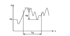
任意の時刻から始まるリフト油圧振幅サンプリング時間Taの間のリフト油圧Pの最大値と最小値を常に検出しておき、この最大値と最小値の差のリフト油圧振幅最大値Haがリフト油圧振幅閾値Hj以上であれば、振動が発生したと判断する。なお、リフト油圧振幅サンプリング時間Taとリフト油圧振幅閾値Hjは予め実車テストで振動発生が確認されている値とする。
【0033】
第4例の車体揺動計測による振動検出方法を以下に説明する。
車体前部(好ましくはマスト11aの近傍又は座席近傍)に上下方向又は前後方向の加速度を計測する加速度計を設けて、車体のピッチング揺動を計測する。本発明者らは加速度計によるデータはリフト油圧データと略同位相であることを実車テストにより確認しており、ゼロを中心に振動するデータであるので図6で説明した周波数計測による判断方法、図8で説明した絶対値計測による判断方法、又は図9で説明した振幅計測による判断方法を適用して振動発生の有無を検出する。
加速度データによれば、積載荷重の大きさに対応した振幅の加速度が精度よく計測される。振動発生の検出方法として図8で説明した絶対値による判断方法又は図9で説明した振幅計測による判断方法を適用する場合、加速度閾値として抑制制御を適用したい積載荷重に対応した値を設定することで、振動発生検出が可能となる。これによりリフト油圧Pを利用する場合の、積載荷重の大小により制御を適用するか否かを判断する制御適用判断手段21は必要としなくなる。なお、加速度による振動発生を検出する方法によるときの振動抑制手段と解除手段はリフト油圧Pを利用して振動発生を検出するときと同一のものを適用する。
【0034】
次に、振動抑制手段23の他の例として、レバー指令値をフィルタリングして滑らかな電磁弁指令値を得る方法と、電磁弁指令値を微小勾配でレバー指令値へ近づける方法とを説明する。さらに、レバー指令値とは異なる値へ電磁弁指令値を近づける方法を説明する。
第1例のローパスフィルタにより電磁弁指令値Sdを滑らかにする方法を図10により説明する。
通常操作時は、レバー操作量Levを入力としレバー指令値を演算するレバー指令値演算部91でレバー指令値Srが演算され、電磁弁指令値Sdとして電磁弁16に指令される。ローパスフィルターはレバー指令値演算部91の前の場所F1、又は後の場所F2のいずれかに挿入してもよく、これにより滑らかな電磁弁指令値Sdを得る。
【0035】
また、第2例の電磁弁指令値Sdを微小勾配でレバー指令値Srへ近づける方法を図11により説明する。
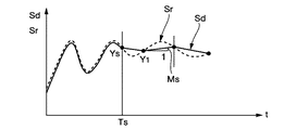
レバー指令値Srを点線で、電磁弁指令値Sdを実線で示す。抑制制御開始時刻Ts以前は通常操作であるため、レバー指令値Srが電磁弁指令値Sdとして出力されている。抑制制御開始時刻Tsの抑制制御開始点Ysにおいてレバー指令値Srが減少方向であれば、微小勾配絶対値Msを負に設定して電磁弁指令値Sdをレバー指令値Srに近づけるように変化させる。電磁弁指令値Sdとレバー指令値Srとの第1交点Y1にて、レバー指令値Srが増加方向であれば、微小勾配絶対値Msを正に設定して、電磁弁指令値Sdをレバー指令値Srに近づけるように変化させる。その後、この動作を繰り返して電磁弁指令値Sdがレバー指令値Srに少しずつ近づいてゆく。
【0036】
第3例として、電磁弁指令値Sdがレバー指令値Srとは異なる値を目標として近づく方法を説明する。
図12にリフト油圧P、レバー指令値Srを点線で、電磁弁指令値Sdを実線で、振動発生の判断時点以前のレバー指令値に基づく目標値を二点鎖線で示す。振動検出を判断した時刻Tsの直前のリフト油圧Pのピークをもつ時刻Tp1とTp2のときのレバー指令値Sr1とSr2の平均値Sraを電磁弁指令値Sdを近づける目標値と設定する。電磁弁指令値Sdとして、ローパスフィルタにより滑らかに近づける場合の曲線Cfまたは微小勾配により徐々に近づける場合の曲線Ckのどちらでもよい。この方法によると、目標値Sraがオペレータの一定に保とうとするレバー操作量に近い位置に選択されるので、振動抑制制御しているにも拘らずオペレータが自分で操作しているという操作感覚が得られる。
【0037】
次に、抑制制御終了時刻Te以降の解除手段24の他の例を説明する。
図13(a)に示すように、抑制制御終了時刻Teのときの電磁弁入力記憶値Smを初期値としレバー指令値Srを目標値としてローパスフィルタを介して滑らかにフィルタリングした値を電磁弁指令値Sdとして使用する。これにより、ショックなくレバー指令値Srに移行させる。また図13(b)においては、レバー指令値Srが一定のときは、微小接近勾配Mbで電磁弁指令値をレバー指令値に近づけ、レバー指令値が変化しているときは、このときのレバー指令値勾配mrで電磁弁指令値Sdをレバー指令値Srに近づける。
なお、レバー指令値Srの指令値の最大値を100%としたとき、レバー指令値Srの指令値が例えば5%という小さい値又は、例えば95%という大きい値のときには、オペレータのレバー操作が緊急であるため、ローパスフィルタの特性をより高速化し、接近勾配の大きさをより大きくして、短い時間で電磁弁指令値Sdをレバー指令値Srに近づけてもよい。
【0038】
なお、本実施形態で説明したリフト油圧検出器18の取着場所、リフト油圧Pの比較値、制御持続設定時間DT、振動検出手段で利用する振動データの他の例を次に説明する。
本実施形態ではリフト油圧検出器18の位置を電磁弁16に取着するとしているが、リフトシリンダ13のボトム室に取着してもよい。また、電磁弁16からボトム室の間であればどこに取着しても差し支えない。
本実施形態では振動検出手段におけるリフト油圧Pの大きさの判断にリフト保持圧Pkと比較しているが、リフト保持圧Pkに実車データにより求めた確実に振動発生を検出できる付加圧dPを加えた値と比較してもよい。また、作業又は積載重量によって付加圧dPをゼロと設定してもよい。
本実施形態では抑制制御は制御開始時刻Tsから制御持続設定時間DTだけ続行するとしているが、オペレータの操作割り込みで制御が解除され通常操作に戻ってゆく場合が多いので、抑制制御は完了させない、即ちDTを無限大に設定しておいても差し支えない。
本実施形態では作業機アクチュエータとしてのリフトシリンダ13の油圧又は車体の加速度信号を利用して振動発生を判断しているが、レバー指令値Sr、電磁弁指令値Sdにより振動発生を判断しても何ら差し支えない。
【0039】
フォークの上昇時を例とした第2実施形態を説明する。
なお、本実施形態のハード構成は第1実施形態と同一とする。
本実施形態ではフォーク10の上昇時のリフト油圧Pにより振動発生を判断する方法を説明する。図14にフォーク12の上昇時のリフト油圧Pを示す。リフトレバー17をフォーク12の上げ方向に操作すると電磁弁16が開いてリフトシリンダ13のボトム室へ油が供給される。このとき、リフト油圧Pはリフト保持圧Pkより大きくなる。その後、リフトレバー操作量Levを急に小さくすると、電磁弁16のリフトシリンダ13のボトム室から油圧タンクに通じる通路面積は急に閉じられ、リフトシリンダ13の伸縮が急減速され、油圧の揺れ戻しが生じて、リフト油圧Pはリフト保持圧Pkよりも大きい値のピークから減少に転じる。リフト油圧Pがリフト保持圧Pkに所定の付加圧dPを加えた値より大きくなって、ピークを持ち、再びリフト保持圧Pkに付加圧dPを加えた値まで戻ってくるまでのリフト油圧持続時間tpが所定のリフト油圧持続判定時間tpsより長いならば、車体持続振動が起きるに充分大きい外乱がノイズによる誤検出もなく発生したと判断する。振動発生と判断した後の処理は第1実施形態で説明した処理と同一であるので、ここでは説明を省く。
【0040】
次に、回転クランプの回転時を例とした第3実施形態を説明する。
図15に示すフォークリフト10の作業機としての回転クランプ51はドラム缶、タイヤ、ロール紙などのワークを把持、回転、運搬、荷下ろしするときのフォークリフト10のアタッチメントであり、フォーク12の替わりに、回転クランプ51がマスト11aに装着されている。回転クランプ51はクランプ装置51a、作業機用アクチュエータとしての回転用油圧モータ51b、クランプ支持基部51cから構成されている。回転用油圧モータ51bは軸Aを中心にエンドレスに回転する。回転用油圧モータ51bと油圧ポンプ14及び油圧タンク15との間には、回転用油圧モータ51bを制御する電磁弁57を介して油圧配管がなされており、電磁弁57への操作指令を与えるモータレバー55が運転席の前面パネル(図示せず)に設けられている。
信号検出器として、回転用油圧モータ51bには車体振動に起因する動的負荷を示すモータ油圧Pmを検出するモータ油圧検出器54が取着されている。また、モータレバー55にはモータレバー操作量Levmを検出するモータレバー操作量検出器56が取着されている。コントローラ20にはモータ油圧検出器54とモータレバー操作量検出器56からの検出信号が入力回路(図示せず)を介して入力されて、コントローラ20からは出力駆動部(図示せず)を介して電磁弁57を制御する電磁弁指令値Sdmが出力されている。
回転用油圧モータ51bのモータレバー55を急激に操作すると、把持しているワークの慣性で車体が左右上下に揺れ、回転用油圧モータ51bの油圧は振動する。回転用油圧モータ51bの油圧Pmはリフト油圧Pのような明確な保持油圧がなく、ゼロを中心とした振動であるため、振動発生の検出は第1実施形態で説明した振幅、周波数の方法による。振動発生と判断した後の処理は第1実施形態と同一であるのでここでは説明を省く。
本実施形態のときも、把持したワークの回転運動の急加減速に起因する車体振動の検出を回転用油圧モータ51bの油圧によらず、第1実施形態と同様に加速度検出器からの加速度信号又は回転クランプ51を支持しているリフトシリンダ13のリフト油圧Pによって検出してもよい。
【0041】
以上、本発明によると、始まろうとする車体振動を検出できるリフトシリンダと回転用油圧モータなどの作業機アクチュエータの油圧変動、車体上下方向の加速度変動、作業機操作レバーの操作量変動、又は電磁弁指令値変動により振動が発生したことを確実に判断し、振動発生との判断後は、持続振動しようとするレバー指令値を直接電磁弁指令値とせず、連続的かつ滑らかな電磁弁指令値を演算して電磁弁へ指令している。これにより、車体振動がレバー指令値に影響されないので車体の持続振動の発生を予防でき、また持続振動発生後は迅速に抑制できる。
【図面の簡単な説明】
【図1】第1実施形態のハード構成図である。
【図2】第1実施形態のコントローラのフローチャートである。
【図3】第1実施形態のリフトレバー操作量、レバー指令値、電磁弁指令値、リフト油圧の時間的変化を示し、振動検出方法と狭閾値を越える操作割り込みの説明図である。
【図4】第1実施形態の最小閾値を越える操作割り込みの説明図である。
【図5】第1実施形態の抑制制御終了後における電磁弁指令値の所定勾配によるレバー指令値への接近方法の説明図である。
【図6】第1実施形態のリフト油圧の周波数計測による振動検出方法の説明図である。
【図7】第1実施形態のリフト油圧の周波数計測による振動検出方法のフローチャートである。
【図8】第1実施形態のリフト油圧の絶対値計測による振動検出方法の説明図である。
【図9】第1実施形態のリフト油圧の最小最大値計測による振動検出方法の説明図である。
【図10】第1実施形態の振動抑制手段におけるリフトレバーと電磁弁間のローパスフィルタ位置の説明図である
【図11】第1実施形態の振動抑制手段における電磁弁指令値の微小勾配によるレバー指令値への追従方法の説明図である。
【図12】第1実施形態の振動抑制手段におけるレバー指令値とは異なる目標値の説明図である。
【図13】第1実施形態の抑制制御終了後の解除手段における電磁弁指令値のレバー指令値への接近方法の説明図である。
【図14】第2実施形態のフォーク上昇時のリフト油圧の説明図である。
【図15】第3実施形態の回転クランプの説明図である。
【符号の説明】
10…フォークリフト、11…車体、11a…マスト、12…フォーク、13…リフトシリンダ、16…電磁弁、17…リフトレバー、18…リフト油圧検出器、19…リフトレバー操作量検出器、20…コントローラ、21…制御適用判断手段、22…振動検出手段、23…振動抑制手段、24…解除手段、リフトレバー操作量…Lev、リフト油圧…P、リフト保持圧…Pk、電磁弁指令値…Sd、レバー指令値…Sr、狭閾値…dLs、広閾値…dLw、最小閾値…Li、最大閾値…La、広狭閾値変更時刻Tws、抑制制御開始時刻…Ts、抑制制御終了時刻…Te。[0001]
BACKGROUND OF THE INVENTION
The present invention relates to a cargo handling control device for a forklift.
[0002]
[Prior art]
In a forklift that has a working machine that can be lifted and lowered by the operator's operation at the front of the vehicle body and that can lift and lower the load and transport it, the lift lever that lifts and lowers the work machine and the tilt lever that tilts the front of the driver's seat It is disposed at a predetermined position of the panel. The operator sits in the driver's seat or operates these work implement operation levers in a standing state (in the case of a reach forklift).
By the way, when the fork is lowered, for example, when the lift lever is operated to lower the fork loaded with load, for example, if there is a disturbance of sudden operation of the lift lever, the movement of the fork is suddenly accelerated and decelerated. Shakes. In such a case, since the operator also shakes, the operator tries to keep the operation amount of the lift lever constant so as not to vibrate in order to reduce the shake.
[0003]
[Problems to be solved by the invention]
However, the conventional forklift has the following problems. Even if the operator tries to keep the operation of the lift lever constant due to the shaking of the vehicle body, the lift lever also shakes in a coordinated manner, resulting in continuous vibration including the entire vehicle body where the operator is interposed. Once sustained vibration occurs, it is difficult to quickly suppress it. In addition, the operator may release the lift lever and wait until the shaking stops. However, since the work must be interrupted during this time, there is a problem that the predetermined handling operability and work efficiency cannot be exhibited.
[0004]
The present invention has been made paying attention to the above-described problems, and includes the shaking of the vehicle body caused by the disturbance and the operation of the working machine operation lever that attempts to keep the working machine operation amount constant despite the shaking. An object of the present invention is to provide a cargo handling control device for an industrial vehicle that can suppress the continuous vibration of the vehicle body that occurs in cooperation.
[0005]
[Means, actions and effects for solving the problems]
In order to achieve the above object, an invention described in a first invention includes a work machine provided at a predetermined position of a vehicle body, a work machine actuator that drives the work machine, and a control valve that controls the work machine actuator. And a load handling control device for a forklift comprising a controller that inputs a lever command signal generated in response to an operation of a work implement operation lever and outputs a control valve command value to the control valve.
It has a detecting means for detecting the lift hydraulic pressure duration from when the lift hydraulic pressure starts to increase from a value smaller than the lift holding pressure, crosses the lift holding pressure, and then returns to the lift holding pressure again after having a peak.
The controller inputs a lift hydraulic pressure duration detected by the detection means, and when the detected lift hydraulic pressure duration is longer than a predetermined lift hydraulic pressure duration determination time, the work implement operating lever is suddenly operated. , It is determined that the continuous vibration that the lever command value continuously vibrates has occurred,
Further, when the controller determines that the continuous vibration has occurred, the control valve at the time when the control valve returns to the lift holding pressure again instead of the control valve command value corresponding to the lever command value. Control valve command value set based on the command value, control valve command value obtained by filtering the lift lever operation amount with a low-pass filter provided between the lift lever and the control valve, lever command value and control valve command If the lever command value is in a decreasing direction when the values cross, the lever command value approaches a lever command value with a predetermined negative minute gradient. If the lever command value increases, the lever command value approaches a lever command value with a predetermined positive minute gradient. Output any one of the control valve command values
It is characterized by.
[0006]
According to the first aspect of the present invention, after detecting that the vehicle body or the lever command value vibrates by the vibration detecting means for detecting the lift hydraulic pressure duration, and after detecting the occurrence of the vibration, the vibration suppressing means continuously The lever command value to be vibrated is not directly used as the control valve command value, but the control valve command value for suppressing the vibration is calculated and commanded to the control valve. Therefore, the fork movement is not affected by the lever command value. Thereby, continuous vibration can be quickly suppressed.
[0007]
According to a second aspect of the present invention, there is provided a work machine provided at a predetermined position of a vehicle body, a work machine actuator that drives the work machine, a control valve that controls the work machine actuator, and an operation of a work machine operation lever. A forklift loading / unloading control device including a controller that inputs a lever command signal generated in response to the control valve and outputs a control valve command value to the control valve;
A detecting means for detecting a lift hydraulic frequency obtained from a plurality of peak intervals of lift hydraulic pressure oscillating around the lift holding pressure;
The controller inputs the lift hydraulic frequency detected by the detecting means, and when the absolute value of the difference between the detected lift hydraulic frequency and a predetermined lift hydraulic frequency is smaller than a predetermined frequency, the work implement operating lever is Judging that the lever command value continuously vibrates due to the sudden operation,
Further, when the controller determines that the continuous vibration has occurred, the control valve at the time when the control valve returns to the lift holding pressure again instead of the control valve command value corresponding to the lever command value. Control valve command value set based on the command value, control valve command value obtained by filtering the lift lever operation amount with a low-pass filter provided between the lift lever and the control valve, lever command value and control valve command If the lever command value is in a decreasing direction when the values cross, the lever command value approaches a lever command value with a predetermined negative minute gradient. If the lever command value increases, the lever command value approaches a lever command value with a predetermined positive minute gradient. Output any one of the control valve command values
Characterized by
[0008]
According to the second aspect of the invention, after detecting that the vehicle body or lever command value vibrates by the vibration detecting means for detecting the lift hydraulic frequency and detecting the occurrence of vibration, the vibration suppressing means tries to continuously vibrate. The lever command value to be used is not directly used as the control valve command value, but a control valve command value for suppressing vibration is calculated and commanded to the control valve. Therefore, the fork movement is not affected by the lever command value. Thereby, continuous vibration can be quickly suppressed.
[0009]
According to a third aspect of the present invention, there is provided a work machine provided at a predetermined position of a vehicle body, a work machine actuator that drives the work machine, a control valve that controls the work machine actuator, and an operation of a work machine operation lever. A forklift loading / unloading control device including a controller that inputs a lever command signal generated in response to the control valve and outputs a control valve command value to the control valve;
A detecting means for detecting a lift hydraulic pressure absolute value defined by an absolute value of a difference between the lift hydraulic pressure and the lift holding pressure;
The controller inputs the lift hydraulic pressure absolute value detected by the detection means, and when the detected lift hydraulic pressure absolute value is larger than a predetermined absolute lift hydraulic pressure threshold, the work implement operating lever is suddenly operated, Judge that continuous vibration that the lever command value continuously vibrates has occurred,
Further, when the controller determines that the continuous vibration has occurred, the control valve at the time when the control valve returns to the lift holding pressure again instead of the control valve command value corresponding to the lever command value. Control valve command value set based on the command value, control valve command value obtained by filtering the lift lever operation amount with a low-pass filter provided between the lift lever and the control valve, lever command value and control valve command If the lever command value is in a decreasing direction when the values cross, the lever command value approaches a lever command value with a predetermined negative minute gradient. If the lever command value increases, the lever command value approaches a lever command value with a predetermined positive minute gradient. Output any one of the control valve command values
It is characterized by.
[0010]
According to the invention described in the third aspect of the invention, after detecting that the vehicle body or the lever command value vibrates by the vibration detecting means for detecting the lift hydraulic pressure absolute value and detecting the occurrence of vibration, the vibration suppressing means continuously The lever command value to be vibrated is not directly used as the control valve command value, but the control valve command value for suppressing the vibration is calculated and commanded to the control valve. Therefore, the fork movement is not affected by the lever command value. Thereby, continuous vibration can be quickly suppressed.
[0011]
According to a fourth aspect of the present invention, there is provided a work machine provided at a predetermined position of a vehicle body, a work machine actuator that drives the work machine, a control valve that controls the work machine actuator, and an operation of a work machine operation lever. A forklift loading / unloading control device including a controller that inputs a lever command signal generated in response to the control valve and outputs a control valve command value to the control valve;
A detecting means for detecting a lift hydraulic pressure amplitude defined by a difference between a maximum value and a minimum value of the lift hydraulic pressure;
The controller inputs the lift hydraulic pressure amplitude detected by the detection means, and when the detected lift hydraulic pressure maximum value is larger than a predetermined lift hydraulic pressure amplitude threshold value, the work implement operating lever is suddenly operated, Judge that continuous vibration that the lever command value continuously vibrates has occurred,
Further, when the controller determines that the continuous vibration has occurred, the control valve at the time when the control valve returns to the lift holding pressure again instead of the control valve command value corresponding to the lever command value. Control valve command value set based on the command value, control valve command value obtained by filtering the lift lever operation amount with a low-pass filter provided between the lift lever and the control valve, lever command value and control valve command If the lever command value is in a decreasing direction when the values cross, the lever command value approaches a lever command value with a predetermined negative minute gradient. If the lever command value increases, the lever command value approaches a lever command value with a predetermined positive minute gradient. Output any one of the control valve command values
Characterized by
[0012]
According to the fourth aspect of the present invention, after detecting that the vehicle body or the lever command value vibrates by the vibration detecting means for detecting the lift hydraulic pressure amplitude, and after detecting the occurrence of vibration, the vibration suppressing means detects the continuous vibration. The lever command value to be tried is not directly used as a control valve command value, but a control valve command value for suppressing vibration is calculated and commanded to the control valve. Therefore, the fork movement is not affected by the lever command value. Thereby, continuous vibration can be quickly suppressed.
[0013]
According to a fifth aspect of the present invention, there is provided a work machine provided at a predetermined position of a vehicle body, a work machine actuator that drives the work machine, a control valve that controls the work machine actuator, and an operation of a work machine operation lever. A forklift loading / unloading control device including a controller that inputs a lever command signal generated in response to the control valve and outputs a control valve command value to the control valve;
A detecting means for detecting the vehicle body swing acceleration measured from the pitching swing of the vehicle body by an accelerometer;
The controller inputs the vehicle body swing acceleration detected by the detecting means, and when the detected vehicle body swing acceleration is larger than an acceleration threshold corresponding to the load, the work implement operating lever is suddenly operated. , It is determined that the continuous vibration that the lever command value continuously vibrates has occurred,
Further, when the controller determines that the continuous vibration has occurred, the control valve at the time when the control valve returns to the lift holding pressure again instead of the control valve command value corresponding to the lever command value. Control valve command value set based on the command value, control valve command value obtained by filtering the lift lever operation amount with a low-pass filter provided between the lift lever and the control valve, lever command value and control valve command If the lever command value is in a decreasing direction when the values cross, the lever command value approaches a lever command value with a predetermined negative minute gradient. If the lever command value increases, the lever command value approaches a lever command value with a predetermined positive minute gradient. Output any one of the control valve command values
It is characterized by.
[0014]
According to the fifth aspect of the present invention, after detecting that the vehicle body or the lever command value vibrates by the vibration detecting means for detecting the vehicle body swing acceleration and detecting the occurrence of vibration, the vibration suppressing means continuously The lever command value to be vibrated is not directly used as the control valve command value, but the control valve command value for suppressing the vibration is calculated and commanded to the control valve. Therefore, the fork movement is not affected by the lever command value. Thereby, continuous vibration can be quickly suppressed.
[0015]
According to a sixth aspect of the present invention, there is provided a rotary clamp provided at a predetermined position of a vehicle body as an attachment for a forklift, a rotary hydraulic motor for driving the rotary clamp, a control valve for controlling the rotary hydraulic motor, and a work implement operation In a forklift cargo handling control device including a controller that inputs a lever command signal generated in response to an operation of a lever and outputs a control valve command value to the control valve.
Detecting means for detecting a motor hydraulic amplitude or a motor hydraulic frequency obtained from vibration of hydraulic pressure generated in the rotating hydraulic motor as the vehicle body swings;
The controller inputs a motor hydraulic amplitude or motor hydraulic frequency of the rotary hydraulic motor detected by the detecting means, and the detected motor hydraulic amplitude or motor hydraulic frequency is greater than a predetermined motor hydraulic amplitude or a predetermined motor hydraulic frequency. If it is larger, it is determined that a continuous vibration in which the lever command value continuously vibrates due to the sudden operation of the work implement operation lever,
Further, when the controller determines that the continuous vibration has occurred, the control valve at the time when the control valve returns to the lift holding pressure again instead of the control valve command value corresponding to the lever command value. Control valve command value set based on the command value, control valve command value obtained by filtering the lift lever operation amount with a low-pass filter provided between the lift lever and the control valve, lever command value and control valve command If the lever command value is in a decreasing direction when the values cross, the lever command value approaches a lever command value with a predetermined negative minute gradient. If the lever command value increases, the lever command value approaches a lever command value with a predetermined positive minute gradient. Output any one of the control valve command values
It is characterized by.
[0016]
According to the sixth aspect of the invention, the vibration detecting means for detecting the motor hydraulic pressure amplitude or the motor hydraulic frequency detects that the vehicle body or the lever command value vibrates, and after detecting the occurrence of vibration, the vibration suppressing means Thus, the lever command value to be continuously vibrated is not directly used as the control valve command value, but the control valve command value for suppressing the vibration is calculated and commanded to the control valve. Accordingly, the movement of the rotary clamp is not affected by the lever command value. Thereby, continuous vibration can be quickly suppressed.
According to a seventh aspect of the present invention, in any one of the first to sixth aspects of the present invention, when the controller detects a vibration and the lift lever operation amount exceeds a predetermined threshold, the control valve Release means for calculating the command value so as to approach the lever command value smoothly and outputting the command value to the control valve is provided.
According to the seventh aspect of the present invention, when the lever operation amount exceeds a predetermined threshold immediately after it is determined that vibration has occurred, it is determined that there has been an operation interruption by the operator, and the control valve command value is brought closer to the lever command value smoothly. . Thereby, since an operator's intention is reflected in control valve control, the release means suitable for operation feeling is obtained.
According to an eighth aspect of the present invention, in any one of the first to sixth aspects of the present invention, the control valve command value approaches the smooth cook lever command value after the suppression control by the vibration suppression means has elapsed for a predetermined time. Release means for calculating and outputting to a control valve is provided.
According to the eighth aspect of the present invention, after a predetermined time elapses, the control valve command value is calculated so as to approach the lever command value smoothly and output to the control valve. Output as command value. Thereby, after the suppression control for a predetermined time is completed, it is possible to smoothly return to the normal operation.
[0017]
DETAILED DESCRIPTION OF THE INVENTION
Embodiments according to the present invention will be described below with reference to the drawings.
First, a description will be given of a first embodiment in which the fork is lowered.
FIG. 1 shows a hardware configuration.
A
[0018]
As a signal detector, a lift
[0019]
Detection signals from the lift
[0020]
FIG. 2 shows a flowchart of the
First, in the control application determination means 21 shown in FIG. 2, a static hydraulic pressure corresponding to the load on the
[0021]
Next, a vibration detection method by the vibration detection means 22 will be described. When the lift lever operation amount Lev is zero as shown in FIG. 3 before the time (hereinafter referred to as t) is zero, the lift hydraulic pressure P has a lift holding pressure Pk corresponding to the load on the
According to the flow chart of the vibration detecting means 22 in FIG. 2, the lift hydraulic pressure P starts to increase from a value smaller than the lift holding pressure Pk, crosses the lift holding pressure Pk, has a peak, and then returns to the lift holding pressure Pk again. If the lift hydraulic pressure duration time tp is longer than the predetermined lift hydraulic pressure duration determination time tps, it is determined that there is a sufficiently large disturbance to cause the vehicle body continuous vibration (S23), and the process proceeds to the next vibration suppression means 23. In order to prevent erroneous detection due to noise even when the lift oil pressure P is greater than the lift holding pressure Pk, the occurrence of vibration is determined by adding a temporal condition of the lift oil pressure duration determination time tps. If the lift oil pressure P is greater than the lift holding pressure Pk, but the lift oil pressure duration tps is shorter than the lift oil pressure predetermined duration, it is determined that there is a false detection due to noise, and the lever command value Sr is set as the solenoid valve command value Sd (S25). ) Perform normal operation. When the lift hydraulic pressure P is smaller than the lift holding pressure Pk, it is determined that the disturbance is small, and the lever command value Sr is set to the solenoid valve command value Sd and a normal operation is performed.
[0022]
In the
The canceling
[0023]
First, it is determined whether or not the time t is before the suppression control end time Te (S27). If it is before, it is determined whether or not there is an operation by the operator.
The lift lever operation amount Lev is between the minimum threshold Li and the maximum threshold La, and the lift lever additional operation amount absolute value dLev based on the lift lever operation amount Lev at the control start time Ts is greater than the wide threshold dLw or the narrow threshold dLs. Is larger, it is determined that there is an operation interruption that the operator has operated the
Lift lever operation amount Lev when the absolute value of lift lever operation amount dLev exceeds the narrow threshold value dLs and then the absolute value of lift lever operation amount Lev is between the minimum threshold value Li and the maximum threshold value La, lever command value Sr, The temporal changes in the solenoid valve command value Sd and the lift hydraulic pressure P are shown after the operation interruption time To in FIG. In this case, the solenoid valve command value Sd is made closer to the lever command value gradient mr at the operation interruption point Z1 in the direction in which the solenoid valve command stored value Sm matches the lever command value Sr (S33). The matched solenoid valve command value Sd takes the lever command value Sr.
When the additional operation amount absolute value dLev is smaller than the wide threshold value dLw or the narrow threshold value dLs, it is determined that the lift lever operation amount Lev of the operator is minute and there is no operation interruption, and the solenoid valve command value Sd is stored in the solenoid valve command stored value. Sm is maintained (S32).
[0024]
Next, when the lift lever operation amount Lev is smaller than the minimum threshold value Li or larger than the maximum threshold value La, it is determined that there is an operation interruption in which the operator has operated the
[0025]
Further, if the time is after the suppression control end time Te, as shown in FIG. 5, a gradient Me after a predetermined end time in a direction in which the solenoid valve command value Sd is made to coincide with the lever command value Sr from the solenoid valve command stored value Sm. (S35). The matched solenoid valve command value Sd takes the lever command value Sr.
[0026]
According to the present embodiment, if the lift hydraulic pressure is longer than the predetermined hydraulic pressure and is longer than the predetermined time, it is determined that a disturbance causing the vehicle body continuous vibration has occurred. The value immediately before the determination is kept constant as it is, and the fork movement is not affected by the lever command value that vibrates, so that the vehicle body vibration is quickly suppressed without being sustained.
[0027]
Since the swing range of the lift lever operation amount is large until a predetermined time has passed immediately after it is determined that vibration has occurred, a wide threshold dLw is set, and when the lift lever operation amount exceeds this threshold dLw, an operation interruption by the operator is performed. The electromagnetic valve command value is made close to the lever command value corresponding to the lift lever operation amount. After the wide / narrow threshold change time Tws after the determination of the occurrence of vibration, the swing range of the lift lever operation amount is small, so the threshold value dLs is changed to a narrow width and the presence / absence of operation interruption is similarly determined.
[0028]
Further, when the lift lever operation amount is operated to zero or a value close to the maximum and exceeds the minimum threshold Li or the maximum threshold La, it is determined that the operator has operated the lift lever greatly for emergency, and at a predetermined gradient Mw. The solenoid valve command value is brought close to the lever command value, and after matching, the lever command value is output as the solenoid valve command value.
As a result, when a lever operation exceeding a predetermined threshold value is performed even during a predetermined time during which the suppression control continues, the operator's will is reflected in the electromagnetic valve control, so that a cargo handling control device suitable for the operation feeling can be obtained.
[0029]
In this way, a continuous and smooth solenoid valve command value is calculated and output to the solenoid valve so that the solenoid valve command value at the time point when the suppression control for a predetermined time is completed is approximated to the lever command value. Since the command value is output as the electromagnetic valve command value, it is possible to smoothly return to the normal operation after completion of the suppression control for a predetermined time.
[0030]
Next, another example of the
First, as another example of the
The vibration detection method by the frequency measurement of the lift hydraulic pressure of the first example will be described below.
As shown in FIG. 6, when the lift hydraulic pressure P oscillating around the lift holding pressure Pk is larger than a predetermined frequency measurement threshold Pp, the first peak time t1 and the second peak time t2 of the lift hydraulic pressure P. The third peak time t3 and the like are measured, and a time T12 between the first and second peaks, a time T23 between the second and third peaks, and the like are calculated. The lift hydraulic frequency Fq that vibrates is obtained by averaging the reciprocals of T12, T23, etc. from the time T12, T23, etc. of these peak intervals, and this lift hydraulic frequency Fq and the representative vehicle body continuous vibration frequency Fm that has been measured in advance. If the absolute value of the difference between the two is smaller than a predetermined frequency threshold value Df, it is determined that vehicle body continuous vibration has occurred. Further, a frequency obtained by dividing the representative vehicle body continuous vibration frequency Fm by an even number due to the vehicle body characteristics and the hydraulic characteristics may also appear as the vehicle body continuous vibration. Therefore, as shown in FIG. 7, after comparing the absolute value of the difference between the lift hydraulic frequency Fq and the representative vehicle body continuous vibration frequency Fm (S71), the lift hydraulic frequency Fq and the representative vehicle body continuous vibration frequency Fm are halved. The absolute value of the difference from the one and the absolute value of the difference from the quarter are compared (S72 to S73), and when each difference is smaller than the predetermined frequency threshold value Df, it is determined that the vehicle body continuous vibration has occurred. If it is large, it is determined that it has not occurred (S75). Further, when the lift hydraulic pressure P is larger than a predetermined frequency measurement threshold value Pp, the frequency Fq may be obtained from the time between the first bottom B1 and the second bottom B2 of the lift hydraulic pressure P, etc. The frequency Fq may be obtained from the time between the first crossing point C1 and the second crossing point C2 at which the holding pressure Pk crosses with a positive slope, the time between the second crossing point C2 and the third crossing point C3, or the like. .
Note that the frequency Fq may be obtained when the amplitude of the lift oil pressure P is greater than a predetermined set value.
[0031]
A method for detecting vibration based on the absolute value of the lift oil pressure P in the second example will be described with reference to FIG.
When the absolute value of the difference between the lift hydraulic pressure P and the lift holding pressure Pk becomes greater than the absolute lift hydraulic pressure threshold Pq, which has been confirmed in advance in the actual vehicle test to generate continuous vehicle body vibration, it is determined that vibration has occurred. In order to avoid erroneous determination, it is determined that vibration has occurred when the number of times greater than the absolute lift hydraulic pressure threshold Pq during the absolute lift hydraulic pressure sampling time Tj starting from an arbitrary time is equal to or greater than the determination count Nj.
[0032]
A method for detecting vibration based on the amplitude of the lift oil pressure P in the third example will be described with reference to FIG.
The maximum value and the minimum value of the lift oil pressure P during the lift oil pressure amplitude sampling time Ta starting from an arbitrary time are always detected, and the lift oil pressure maximum value Ha that is the difference between the maximum value and the minimum value is the lift oil pressure amplitude threshold value. If it is equal to or higher than Hj, it is determined that vibration has occurred. The lift hydraulic pressure amplitude sampling time Ta and the lift hydraulic pressure amplitude threshold value Hj are values that have been confirmed to have vibrations in advance in an actual vehicle test.
[0033]
A vibration detection method by vehicle body swing measurement of the fourth example will be described below.
An accelerometer that measures vertical or longitudinal acceleration is provided in the front part of the vehicle body (preferably in the vicinity of the
According to the acceleration data, an acceleration having an amplitude corresponding to the magnitude of the loaded load is accurately measured. When the determination method based on the absolute value described in FIG. 8 or the determination method based on the amplitude measurement described in FIG. 9 is applied as the vibration generation detection method, a value corresponding to the loaded load to which suppression control is to be applied is set as the acceleration threshold value. Thus, vibration generation can be detected. As a result, when the lift hydraulic pressure P is used, the control
[0034]
Next, as another example of the
A method of smoothing the solenoid valve command value Sd by the low-pass filter of the first example will be described with reference to FIG.
During normal operation, the lever command value Sr is calculated by the lever command
[0035]
Further, a method of bringing the solenoid valve command value Sd of the second example close to the lever command value Sr with a slight gradient will be described with reference to FIG.
The lever command value Sr is indicated by a dotted line, and the solenoid valve command value Sd is indicated by a solid line. Since the operation is a normal operation before the suppression control start time Ts, the lever command value Sr is output as the electromagnetic valve command value Sd. If the lever command value Sr is in a decreasing direction at the suppression control start point Ys at the suppression control start time Ts, the minute gradient absolute value Ms is set to be negative and the electromagnetic valve command value Sd is changed to approach the lever command value Sr. . If the lever command value Sr is in the increasing direction at the first intersection Y1 between the solenoid valve command value Sd and the lever command value Sr, the minute gradient absolute value Ms is set to be positive and the solenoid valve command value Sd is set to the lever command. The value is changed so as to approach the value Sr. Thereafter, this operation is repeated, and the solenoid valve command value Sd gradually approaches the lever command value Sr.
[0036]
As a third example, a method will be described in which the solenoid valve command value Sd approaches a value different from the lever command value Sr as a target.
FIG. 12 shows the lift hydraulic pressure P, the lever command value Sr as a dotted line, the solenoid valve command value Sd as a solid line, and the target value based on the lever command value before the determination of occurrence of vibration as a two-dot chain line. The average value Sra of the lever command values Sr1 and Sr2 at the times Tp1 and Tp2 having the peak of the lift hydraulic pressure P immediately before the time Ts at which the vibration detection is determined is set as a target value that brings the solenoid valve command value Sd closer. The electromagnetic valve command value Sd may be either a curve Cf when it is made closer to smooth by a low-pass filter or a curve Ck when it is made closer to a slight gradient. According to this method, since the target value Sra is selected at a position close to the lever operation amount to be kept constant by the operator, there is an operation feeling that the operator is operating himself / herself despite vibration suppression control. can get.
[0037]
Next, another example of the release means 24 after the suppression control end time Te will be described.
As shown in FIG. 13 (a), a value that is smoothly filtered through a low-pass filter using the solenoid valve input storage value Sm at the suppression control end time Te as an initial value and the lever command value Sr as a target value is used as the solenoid valve command. Used as the value Sd. As a result, the lever command value Sr is shifted to without a shock. In FIG. 13B, when the lever command value Sr is constant, the solenoid valve command value is brought close to the lever command value with a small approach gradient Mb, and when the lever command value is changed, the lever at this time The solenoid valve command value Sd is brought close to the lever command value Sr with the command value gradient mr.
When the maximum command value of the lever command value Sr is 100% and the command value of the lever command value Sr is a small value such as 5% or a large value such as 95%, the operator's lever operation is urgent. Therefore, the characteristics of the low-pass filter may be increased, the approach gradient may be increased, and the solenoid valve command value Sd may be brought closer to the lever command value Sr in a short time.
[0038]
Note that another example of the vibration data used in the attachment location of the lift
In this embodiment, the position of the lift
In this embodiment, the magnitude of the lift hydraulic pressure P in the vibration detection means is compared with the lift holding pressure Pk. However, an additional pressure dP that can reliably detect the occurrence of vibration is added to the lift holding pressure Pk. You may compare with the value. Further, the additional pressure dP may be set to zero depending on the work or the loaded weight.
In the present embodiment, the suppression control is continued from the control start time Ts for the control duration set time DT. However, since the control is often canceled by the operator's operation interruption and returns to the normal operation, the suppression control is not completed. That is, DT may be set to infinity.
In the present embodiment, the occurrence of vibration is determined using the hydraulic pressure of the
[0039]
A second embodiment will be described, taking as an example when the fork is raised.
The hardware configuration of this embodiment is the same as that of the first embodiment.
In the present embodiment, a method for determining the occurrence of vibration based on the lift oil pressure P when the
[0040]
Next, a third embodiment in which the rotation of the rotary clamp is taken as an example is described.
A
As a signal detector, a motor
When the
Also in the present embodiment, the detection of the vehicle body vibration caused by the sudden acceleration / deceleration of the rotational motion of the gripped workpiece is not dependent on the hydraulic pressure of the rotation
[0041]
As described above, according to the present invention, hydraulic pressure fluctuations of work implement actuators such as a lift cylinder and a rotation hydraulic motor that can detect vehicle body vibration to be started, acceleration fluctuations in the vertical direction of the vehicle body, fluctuations in the operation amount of the work implement operation lever, or solenoid valves After having determined that vibration has occurred due to command value fluctuation, and after determining that vibration has occurred, the lever command value to be continuously vibrated is not directly used as the solenoid valve command value, but a continuous and smooth solenoid valve command value is used. Calculated and commanded to solenoid valve. Thereby, since the vehicle body vibration is not affected by the lever command value, the occurrence of the continuous vibration of the vehicle body can be prevented, and it can be quickly suppressed after the continuous vibration occurs.
[Brief description of the drawings]
FIG. 1 is a hardware configuration diagram of a first embodiment.
FIG. 2 is a flowchart of the controller of the first embodiment.
FIG. 3 is an explanatory diagram of a vibration detection method and an operation interruption exceeding a narrow threshold value, showing temporal changes in a lift lever operation amount, a lever command value, a solenoid valve command value, and a lift hydraulic pressure according to the first embodiment.
FIG. 4 is an explanatory diagram of an operation interrupt exceeding the minimum threshold according to the first embodiment.
FIG. 5 is an explanatory diagram of a method of approaching a lever command value by a predetermined gradient of a solenoid valve command value after the end of the suppression control of the first embodiment.
FIG. 6 is an explanatory diagram of a vibration detection method based on frequency measurement of lift hydraulic pressure according to the first embodiment.
FIG. 7 is a flowchart of a vibration detection method based on frequency measurement of lift hydraulic pressure according to the first embodiment.
FIG. 8 is an explanatory diagram of a vibration detection method based on absolute value measurement of lift hydraulic pressure according to the first embodiment.
FIG. 9 is an explanatory diagram of a vibration detection method by measuring the minimum and maximum values of lift hydraulic pressure according to the first embodiment.
FIG. 10 is an explanatory diagram of a low-pass filter position between the lift lever and the solenoid valve in the vibration suppressing unit of the first embodiment.
FIG. 11 is an explanatory diagram of a method for following a lever command value by a minute gradient of a solenoid valve command value in the vibration suppressing unit of the first embodiment.
FIG. 12 is an explanatory diagram of a target value different from the lever command value in the vibration suppressing unit of the first embodiment.
FIG. 13 is an explanatory diagram of a method of approaching a solenoid command value to a lever command value in the release means after the suppression control according to the first embodiment.
FIG. 14 is an explanatory diagram of lift hydraulic pressure when the fork is raised according to the second embodiment.
FIG. 15 is an explanatory diagram of a rotary clamp according to a third embodiment.
[Explanation of symbols]
DESCRIPTION OF
Claims (8)
リフト油圧がリフト保持圧より小さい値より増加に転じリフト保持圧を横切ってからピークをもった後再びリフト保持圧に戻ってくるまでのリフト油圧持続時間を検出する検出手段を備え、
前記コントローラは、前記検出手段で検出されるリフト油圧持続時間を入力し、前記検出したリフト油圧持続時間が所定のリフト油圧持続判定時間より長い場合、前記作業機操作レバーが急操作されたことによって、レバー指令値が継続して振動する持続振動が起きたと判断し、
さらに前記コントローラは、持続振動が起きたと判断した場合には、前記制御弁に対して、レバー指令値に応じた制御弁指令値の代わりに、再びリフト保持圧に戻ってきた時点での制御弁指令値に基づいて設定した一定の制御弁指令値、リフトレバーと制御弁との間に設けたローパスフィルターによりリフトレバー操作量をフィルタリングして求めた制御弁指令値、レバー指令値と制御弁指令値が交叉したときにレバー指令値が減少方向であれば所定の負の微小勾配でレバー指令値に近づけ、レバー指令値が増加方向であれば所定の正の微小勾配でレバー指令値に近づけた制御弁指令値のいずれか1つを出力するようにしたこと
を特徴とするフォークリフトの荷役制御装置。A work implement provided at a predetermined position of the vehicle body, a work implement actuator for driving the work implement, a control valve for controlling the work implement actuator, and a lever command signal generated in response to an operation of the work implement operation lever are input. And a cargo handling control device for a forklift comprising a controller that outputs a control valve command value to the control valve,
It has a detecting means for detecting the lift hydraulic pressure duration from when the lift hydraulic pressure starts to increase from a value smaller than the lift holding pressure, crosses the lift holding pressure, and then returns to the lift holding pressure again after having a peak.
The controller inputs a lift hydraulic pressure duration detected by the detection means, and when the detected lift hydraulic pressure duration is longer than a predetermined lift hydraulic pressure duration determination time, the work implement operating lever is suddenly operated. , It is determined that the continuous vibration that the lever command value continuously vibrates has occurred,
Further, when the controller determines that the continuous vibration has occurred, the control valve at the time when the control valve returns to the lift holding pressure again instead of the control valve command value corresponding to the lever command value. Control valve command value set based on the command value, control valve command value obtained by filtering the lift lever operation amount with a low-pass filter provided between the lift lever and the control valve, lever command value and control valve command If the lever command value is in a decreasing direction when the values cross, the lever command value approaches a lever command value with a predetermined negative minute gradient. If the lever command value increases, the lever command value approaches a lever command value with a predetermined positive minute gradient. A forklift cargo handling control device characterized in that any one of control valve command values is output.
リフト保持圧を中心にして振動しているリフト油圧の複数のピーク間隔から求めたリフト油圧周波数を検出する検出手段を備え、
前記コントローラは、前記検出手段で検出されるリフト油圧周波数を入力し、前記検出したリフト油圧周波数と所定のリフト油圧周波数との差の絶対値が所定の周波数より小さい場合、前記作業機操作レバーが急操作されたことによって、レバー指令値が継続して振動する持続振動が起きたと判断し、
さらに前記コントローラは、持続振動が起きたと判断した場合には、前記制御弁に対して、レバー指令値に応じた制御弁指令値の代わりに、再びリフト保持圧に戻ってきた時点での制御弁指令値に基づいて設定した一定の制御弁指令値、リフトレバーと制御弁との間に設けたローパスフィルターによりリフトレバー操作量をフィルタリングして求めた制御弁指令値、レバー指令値と制御弁指令値が交叉したときにレバー指令値が減少方向であれば所定の負の微小勾配でレバー指令値に近づけ、レバー指令値が増加方向であれば所定の正の微小勾配でレバー指令値に近づけた制御弁指令値のいずれか1つを出力するようにしたこと
を特徴とするフォークリフトの荷役制御装置。A work implement provided at a predetermined position of the vehicle body, a work implement actuator for driving the work implement, a control valve for controlling the work implement actuator, and a lever command signal generated in response to an operation of the work implement operation lever are input. And a cargo handling control device for a forklift comprising a controller that outputs a control valve command value to the control valve,
A detecting means for detecting a lift hydraulic frequency obtained from a plurality of peak intervals of lift hydraulic pressure oscillating around the lift holding pressure;
The controller inputs the lift hydraulic frequency detected by the detecting means, and when the absolute value of the difference between the detected lift hydraulic frequency and a predetermined lift hydraulic frequency is smaller than a predetermined frequency, the work implement operating lever is Judging that the lever command value continuously vibrates due to the sudden operation,
Further, when the controller determines that the continuous vibration has occurred, the control valve at the time when the control valve returns to the lift holding pressure again instead of the control valve command value corresponding to the lever command value. Control valve command value set based on the command value, control valve command value obtained by filtering the lift lever operation amount with a low-pass filter provided between the lift lever and the control valve, lever command value and control valve command If the lever command value is in a decreasing direction when the values cross, the lever command value approaches a lever command value with a predetermined negative minute gradient. If the lever command value increases, the lever command value approaches a lever command value with a predetermined positive minute gradient. A forklift cargo handling control device characterized in that any one of control valve command values is output.
リフト油圧とリフト保持圧との差の絶対値で定義されるリフト油圧絶対値を検出する検出手段を備え、
前記コントローラは、前記検出手段で検出されるリフト油圧絶対値を入力し、前記検出したリフト油圧絶対値が所定の絶対リフト油圧閾値より大きい場合、前記作業機操作レバーが急操作されたことによって、レバー指令値が継続して振動する持続振動が起きたと判断し、
さらに前記コントローラは、持続振動が起きたと判断した場合には、前記制御弁に対して、レバー指令値に応じた制御弁指令値の代わりに、再びリフト保持圧に戻ってきた時点での制御弁指令値に基づいて設定した一定の制御弁指令値、リフトレバーと制御弁との間に設けたローパスフィルターによりリフトレバー操作量をフィルタリングして求めた制御弁指令値、レバー指令値と制御弁指令値が交叉したときにレバー指令値が減少方向であれば所定の負の微小勾配でレバー指令値に近づけ、レバー指令値が増加方向であれば所定の正の微小勾配でレバー指令値に近づけた制御弁指令値のいずれか1つを出力するようにしたこと
を特徴とするフォークリフトの荷役制御装置。A work implement provided at a predetermined position of the vehicle body, a work implement actuator for driving the work implement, a control valve for controlling the work implement actuator, and a lever command signal generated in response to an operation of the work implement operation lever are input. And a cargo handling control device for a forklift comprising a controller that outputs a control valve command value to the control valve,
A detecting means for detecting a lift hydraulic pressure absolute value defined by an absolute value of a difference between the lift hydraulic pressure and the lift holding pressure;
The controller inputs the lift hydraulic pressure absolute value detected by the detection means, and when the detected lift hydraulic pressure absolute value is larger than a predetermined absolute lift hydraulic pressure threshold, the work implement operating lever is suddenly operated, Judge that continuous vibration that the lever command value continuously vibrates has occurred,
Further, when the controller determines that the continuous vibration has occurred, the control valve at the time when the control valve returns to the lift holding pressure again instead of the control valve command value corresponding to the lever command value. Control valve command value set based on the command value, control valve command value obtained by filtering the lift lever operation amount with a low-pass filter provided between the lift lever and the control valve, lever command value and control valve command If the lever command value is in a decreasing direction when the values cross, the lever command value approaches a lever command value with a predetermined negative minute gradient. If the lever command value increases, the lever command value approaches a lever command value with a predetermined positive minute gradient. A forklift cargo handling control device characterized in that any one of control valve command values is output.
リフト油圧の最大値と最小値の差で定義されるリフト油圧振幅を検出する検出手段を備え、
前記コントローラは、前記検出手段で検出されるリフト油圧振幅を入力し、前記検出したリフト油圧振幅最大値が所定のリフト油圧振幅閾値より大きい場合、前記作業機操作レバーが急操作されたことによって、レバー指令値が継続して振動する持続振動が起きたと判断し、
さらに前記コントローラは、持続振動が起きたと判断した場合には、前記制御弁に対して、レバー指令値に応じた制御弁指令値の代わりに、再びリフト保持圧に戻ってきた時点での制御弁指令値に基づいて設定した一定の制御弁指令値、リフトレバーと制御弁との間に設けたローパスフィルターによりリフトレバー操作量をフィルタリングして求めた制御弁指令値、レバー指令値と制御弁指令値が交叉したときにレバー指令値が減少方向であれば所定の負の微小勾配でレバー指令値に近づけ、レバー指令値が増加方向であれば所定の正の微小勾配でレバー指令値に近づけた制御弁指令値のいずれか1つを出力するようにしたこと
を特徴とするフォークリフトの荷役制御装置。A work implement provided at a predetermined position of the vehicle body, a work implement actuator for driving the work implement, a control valve for controlling the work implement actuator, and a lever command signal generated in response to an operation of the work implement operation lever are input. And a cargo handling control device for a forklift comprising a controller that outputs a control valve command value to the control valve,
A detecting means for detecting a lift hydraulic pressure amplitude defined by a difference between a maximum value and a minimum value of the lift hydraulic pressure;
The controller inputs the lift hydraulic pressure amplitude detected by the detection means, and when the detected lift hydraulic pressure maximum value is larger than a predetermined lift hydraulic pressure amplitude threshold value, the work implement operating lever is suddenly operated, Judge that continuous vibration that the lever command value continuously vibrates has occurred,
Further, when the controller determines that the continuous vibration has occurred, the control valve at the time when the control valve returns to the lift holding pressure again instead of the control valve command value corresponding to the lever command value. Control valve command value set based on the command value, control valve command value obtained by filtering the lift lever operation amount with a low-pass filter provided between the lift lever and the control valve, lever command value and control valve command If the lever command value is in a decreasing direction when the values cross, the lever command value approaches a lever command value with a predetermined negative minute gradient. If the lever command value increases, the lever command value approaches a lever command value with a predetermined positive minute gradient. A forklift cargo handling control device characterized in that any one of control valve command values is output.
加速度計により車体のピッチング揺動から計測した車体揺動加速度を検出する検出手段を備え、
前記コントローラは、前記検出手段で検出される車体揺動加速度を入力し、前記検出した車体揺動加速度が積載荷重に対応した加速度閾値より大きい場合、前記作業機操作レバーが急操作されたことによって、レバー指令値が継続して振動する持続振動が起きたと判断し、
さらに前記コントローラは、持続振動が起きたと判断した場合には、前記制御弁に対して、レバー指令値に応じた制御弁指令値の代わりに、再びリフト保持圧に戻ってきた時点での制御弁指令値に基づいて設定した一定の制御弁指令値、リフトレバーと制御弁との間に設けたローパスフィルターによりリフトレバー操作量をフィルタリングして求めた制御弁指令値、レバー指令値と制御弁指令値が交叉したときにレバー指令値が減少方向であれば所定の負の微小勾配でレバー指令値に近づけ、レバー指令値が増加方向であれば所定の正の微小勾配でレバー指令値に近づけた制御弁指令値のいずれか1つを出力するようにしたこと
を特徴とするフォークリフトの荷役制御装置。A work implement provided at a predetermined position of the vehicle body, a work implement actuator for driving the work implement, a control valve for controlling the work implement actuator, and a lever command signal generated in response to an operation of the work implement operation lever are input. And a cargo handling control device for a forklift comprising a controller that outputs a control valve command value to the control valve,
A detecting means for detecting the vehicle body swing acceleration measured from the pitching swing of the vehicle body by an accelerometer;
The controller inputs the vehicle body swing acceleration detected by the detecting means, and when the detected vehicle body swing acceleration is larger than an acceleration threshold corresponding to the load, the work implement operating lever is suddenly operated. , It is determined that the continuous vibration that the lever command value continuously vibrates has occurred,
Further, when the controller determines that the continuous vibration has occurred, the control valve at the time when the control valve returns to the lift holding pressure again instead of the control valve command value corresponding to the lever command value. Control valve command value set based on the command value, control valve command value obtained by filtering the lift lever operation amount with a low-pass filter provided between the lift lever and the control valve, lever command value and control valve command If the lever command value is in a decreasing direction when the values cross, the lever command value approaches a lever command value with a predetermined negative minute gradient. If the lever command value increases, the lever command value approaches a lever command value with a predetermined positive minute gradient. A forklift cargo handling control device characterized in that any one of control valve command values is output.
車体が揺動するに伴い前記回転用油圧モータに生じる油圧の振動から求めたモータ油圧振幅又はモータ油圧周波数を検出する検出手段を備え、
前記コントローラは、前記検出手段で検出される前記回転油圧モータのモータ油圧振幅又はモータ油圧周波数を入力し、前記検出したモータ油圧振幅又はモータ油圧周波数が所定のモータ油圧振幅又は所定のモータ油圧周波数より大きい場合、前記作業機操作レバーが急操作されたことによって、レバー指令値が継続して振動する持続振動が起きたと判断し、
さらに前記コントローラは、持続振動が起きたと判断した場合には、前記制御弁に対して、レバー指令値に応じた制御弁指令値の代わりに、再びリフト保持圧に戻ってきた時点での制御弁指令値に基づいて設定した一定の制御弁指令値、リフトレバーと制御弁との間に設けたローパスフィルターによりリフトレバー操作量をフィルタリングして求めた制御弁指令値、レバー指令値と制御弁指令値が交叉したときにレバー指令値が減少方向であれば所定の負の微小勾配でレバー指令値に近づけ、レバー指令値が増加方向であれば所定の正の微小勾配でレバー指令値に近づけた制御弁指令値のいずれか1つを出力するようにしたこと
を特徴とするフォークリフトの荷役制御装置。Rotation clamp provided at a predetermined position of the vehicle body as an attachment for a forklift, a rotation hydraulic motor for driving the rotation clamp, a control valve for controlling the rotation hydraulic motor, and generated according to operation of a work implement operation lever In a forklift cargo handling control device comprising a controller that inputs a lever command signal and outputs a control valve command value to the control valve,
Detecting means for detecting a motor hydraulic amplitude or a motor hydraulic frequency obtained from vibration of hydraulic pressure generated in the rotating hydraulic motor as the vehicle body swings;
The controller inputs a motor hydraulic amplitude or motor hydraulic frequency of the rotary hydraulic motor detected by the detecting means, and the detected motor hydraulic amplitude or motor hydraulic frequency is greater than a predetermined motor hydraulic amplitude or a predetermined motor hydraulic frequency. If it is larger, it is determined that a continuous vibration in which the lever command value continuously vibrates due to the sudden operation of the work implement operation lever,
Further, when the controller determines that the continuous vibration has occurred, the control valve at the time when the control valve returns to the lift holding pressure again instead of the control valve command value corresponding to the lever command value. Control valve command value set based on the command value, control valve command value obtained by filtering the lift lever operation amount with a low-pass filter provided between the lift lever and the control valve, lever command value and control valve command If the lever command value is in a decreasing direction when the values cross, the lever command value approaches a lever command value with a predetermined negative minute gradient. If the lever command value increases, the lever command value approaches a lever command value with a predetermined positive minute gradient. A forklift cargo handling control device characterized in that any one of control valve command values is output.
Priority Applications (1)
| Application Number | Priority Date | Filing Date | Title |
|---|---|---|---|
| JP06958799A JP3884590B2 (en) | 1999-03-16 | 1999-03-16 | Forklift cargo handling control device |
Applications Claiming Priority (1)
| Application Number | Priority Date | Filing Date | Title |
|---|---|---|---|
| JP06958799A JP3884590B2 (en) | 1999-03-16 | 1999-03-16 | Forklift cargo handling control device |
Publications (2)
| Publication Number | Publication Date |
|---|---|
| JP2000264597A JP2000264597A (en) | 2000-09-26 |
| JP3884590B2 true JP3884590B2 (en) | 2007-02-21 |
Family
ID=13407120
Family Applications (1)
| Application Number | Title | Priority Date | Filing Date |
|---|---|---|---|
| JP06958799A Expired - Fee Related JP3884590B2 (en) | 1999-03-16 | 1999-03-16 | Forklift cargo handling control device |
Country Status (1)
| Country | Link |
|---|---|
| JP (1) | JP3884590B2 (en) |
Families Citing this family (4)
| Publication number | Priority date | Publication date | Assignee | Title |
|---|---|---|---|---|
| JP2007223745A (en) * | 2006-02-24 | 2007-09-06 | Mitsubishi Heavy Ind Ltd | Container carrying crane, controller for moving body and control method for container carrying crane |
| JP4924584B2 (en) * | 2008-09-24 | 2012-04-25 | 株式会社豊田自動織機 | Pitching suppression device for industrial vehicles |
| JP5902475B2 (en) * | 2011-12-28 | 2016-04-13 | ニチユ三菱フォークリフト株式会社 | Industrial vehicle |
| JP5902474B2 (en) * | 2011-12-28 | 2016-04-13 | ニチユ三菱フォークリフト株式会社 | Industrial vehicle |
-
1999
- 1999-03-16 JP JP06958799A patent/JP3884590B2/en not_active Expired - Fee Related
Also Published As
| Publication number | Publication date |
|---|---|
| JP2000264597A (en) | 2000-09-26 |
Similar Documents
| Publication | Publication Date | Title |
|---|---|---|
| KR101793993B1 (en) | Hydraulic system for operating machine | |
| EP2447423B1 (en) | Rotation control device for working machine | |
| KR100929420B1 (en) | Boom shock absorber of excavator and its control method | |
| US20140320293A1 (en) | Operator alert and height limitation system for load carrying machines | |
| CN101336345B (en) | For controlling the method for movement of vehicular member | |
| JP4840442B2 (en) | Suspended load stabilization device | |
| JP2004270925A (en) | Apparatus for controlling bounce of hydraulically powered equipment | |
| JP2003252592A (en) | Control device and method for forklift | |
| JP5827421B2 (en) | Work machine slow stop device | |
| JP3884590B2 (en) | Forklift cargo handling control device | |
| JPH08151657A (en) | Bucket angle control method for hydraulic shovel | |
| JP5984642B2 (en) | Crane damping control system and crane damping control method | |
| JPH0577622A (en) | Controller for car height control | |
| JP3656783B2 (en) | Crane turning deceleration control device | |
| US20230227290A1 (en) | Dynamic lift-off control device, and crane | |
| JP5774405B2 (en) | Work machine | |
| JP4478538B2 (en) | Capacity control method and capacity control device of hydraulic pump for work machine of work vehicle | |
| JP2706378B2 (en) | Forklift control device | |
| CN105386482B (en) | Method for controlling movement of vehicular member | |
| JPH04353130A (en) | Vibration suppression control device for working device for hydraulic working machine | |
| JPH11222384A (en) | Revolution control device for construction machine | |
| JPH09323521A (en) | Vehicle rolling-over preventing device | |
| JP2011140375A (en) | Travel control device of self-traveling crane | |
| JP3649781B2 (en) | Tower crane safety equipment | |
| JP3692621B2 (en) | Stabilizer for container crane |
Legal Events
| Date | Code | Title | Description |
|---|---|---|---|
| A131 | Notification of reasons for refusal |
Free format text: JAPANESE INTERMEDIATE CODE: A131 Effective date: 20040601 |
|
| A521 | Written amendment |
Free format text: JAPANESE INTERMEDIATE CODE: A523 Effective date: 20040802 |
|
| A02 | Decision of refusal |
Free format text: JAPANESE INTERMEDIATE CODE: A02 Effective date: 20040928 |
|
| A521 | Written amendment |
Free format text: JAPANESE INTERMEDIATE CODE: A523 Effective date: 20041126 |
|
| A521 | Written amendment |
Free format text: JAPANESE INTERMEDIATE CODE: A523 Effective date: 20041220 |
|
| A521 | Written amendment |
Free format text: JAPANESE INTERMEDIATE CODE: A523 Effective date: 20041228 |
|
| A911 | Transfer of reconsideration by examiner before appeal (zenchi) |
Free format text: JAPANESE INTERMEDIATE CODE: A911 Effective date: 20050106 |
|
| A912 | Removal of reconsideration by examiner before appeal (zenchi) |
Free format text: JAPANESE INTERMEDIATE CODE: A912 Effective date: 20050902 |
|
| A521 | Written amendment |
Free format text: JAPANESE INTERMEDIATE CODE: A523 Effective date: 20061011 |
|
| A61 | First payment of annual fees (during grant procedure) |
Free format text: JAPANESE INTERMEDIATE CODE: A61 Effective date: 20061117 |
|
| R150 | Certificate of patent or registration of utility model |
Free format text: JAPANESE INTERMEDIATE CODE: R150 |
|
| FPAY | Renewal fee payment (event date is renewal date of database) |
Free format text: PAYMENT UNTIL: 20091124 Year of fee payment: 3 |
|
| S531 | Written request for registration of change of domicile |
Free format text: JAPANESE INTERMEDIATE CODE: R313531 |
|
| S533 | Written request for registration of change of name |
Free format text: JAPANESE INTERMEDIATE CODE: R313533 |
|
| FPAY | Renewal fee payment (event date is renewal date of database) |
Free format text: PAYMENT UNTIL: 20091124 Year of fee payment: 3 |
|
| R350 | Written notification of registration of transfer |
Free format text: JAPANESE INTERMEDIATE CODE: R350 |
|
| FPAY | Renewal fee payment (event date is renewal date of database) |
Free format text: PAYMENT UNTIL: 20101124 Year of fee payment: 4 |
|
| FPAY | Renewal fee payment (event date is renewal date of database) |
Free format text: PAYMENT UNTIL: 20111124 Year of fee payment: 5 |
|
| FPAY | Renewal fee payment (event date is renewal date of database) |
Free format text: PAYMENT UNTIL: 20111124 Year of fee payment: 5 |
|
| FPAY | Renewal fee payment (event date is renewal date of database) |
Free format text: PAYMENT UNTIL: 20121124 Year of fee payment: 6 |
|
| FPAY | Renewal fee payment (event date is renewal date of database) |
Free format text: PAYMENT UNTIL: 20121124 Year of fee payment: 6 |
|
| S111 | Request for change of ownership or part of ownership |
Free format text: JAPANESE INTERMEDIATE CODE: R313111 |
|
| FPAY | Renewal fee payment (event date is renewal date of database) |
Free format text: PAYMENT UNTIL: 20121124 Year of fee payment: 6 |
|
| R350 | Written notification of registration of transfer |
Free format text: JAPANESE INTERMEDIATE CODE: R350 |
|
| FPAY | Renewal fee payment (event date is renewal date of database) |
Free format text: PAYMENT UNTIL: 20131124 Year of fee payment: 7 |
|
| LAPS | Cancellation because of no payment of annual fees |