JP3883293B2 - Combine - Google Patents
Combine Download PDFInfo
- Publication number
- JP3883293B2 JP3883293B2 JP16666098A JP16666098A JP3883293B2 JP 3883293 B2 JP3883293 B2 JP 3883293B2 JP 16666098 A JP16666098 A JP 16666098A JP 16666098 A JP16666098 A JP 16666098A JP 3883293 B2 JP3883293 B2 JP 3883293B2
- Authority
- JP
- Japan
- Prior art keywords
- cabin
- cleaner
- driving cabin
- grain tank
- air
- Prior art date
- Legal status (The legal status is an assumption and is not a legal conclusion. Google has not performed a legal analysis and makes no representation as to the accuracy of the status listed.)
- Expired - Lifetime
Links
Images


Description
【0001】
【発明の実施の形態】
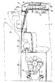
図1に示すように、クローラ走行装置1を原動部に位置するエンジン2からの動力によって駆動して自走するよう構成し、かつ、エンジン2の上方に後部が位置するように配置した運転キャビン3を備える走行機体の前部に、刈取り前処理装置4を昇降操作自在に連結し、この刈取り前処理装置4によって稲、麦などの植立穀稈を引き起こすとともに刈取り、刈取り穀稈を後方に搬送して走行機体に設けてある脱穀装置5に供給し、この脱穀装置5からの脱穀粒を走行機体の運転キャビン3の直後方に位置する穀粒タンク6に貯留するように構成するとともに、この穀粒タンク6の後側に接続する穀粒排出オーガ7によって穀粒タンク6から脱穀粒を取り出すように構成して、コンバインを構成してある。
【0002】
図1及び図3に示すように、前記原動部においてエンジンカバー8の上方にエンジン冷却用空気の吸気室を形成している吸気ケース9の内部にエンジン用のエヤクリーナ10を設け、このエヤクリーナ10の吸気側から延出する吸気筒10aの延出端部に支持されるとともにこの吸気筒10aを介してエヤクリーナ10に接続するプレクリーナ11を運転キャビン3の後側近くに設けてある。すなわち、エンジン2の燃焼用空気をエンジン2の吸引作用により、運転キャビン3の後側でプレクリーナ11に取り入れ、このプレクリーナ11とエヤクリーナ10の両者による清掃作用によってワラ屑などの塵埃を取り除いてからエンジン2に供給するようにしてある。
【0003】
図1に示すように、前記原動部にコンプレッサーを前記エンジン2によって駆動されるように構成して設けるとともに、このコンプレッサーに冷媒循環ホース(図示せず)によって接続するコンデンサ13及びエバポレータ14などを備えるキャビン空調装置を運転キャビン3に設けることにより、運転キャビン内の冷房空調を可能にしてある。キャビン空調装置は、詳しくは図2、図4、図5に示す如く構成してある。
【0004】
すなわち、運転キャビン3の天板3aの上方及び周囲を覆うように形成するとともに天板3aに着脱自在に取り付けるように構成した天板カバー15と前記天板3aとの間に、仕切り板16によってキャビン前方側に位置するスペース部分17aとキャビン後方側に位置するスペース部分17bとに仕切られた空調装置収容スペースを形成し、前記前側スペース部分17aに前記エバポレータ14を、前記後側スペース部分17bに前記コンデンサ13をそれぞれ配置してある。
【0005】
コンデンサ13は、前記冷媒循環ホースが接続する凝縮器13aと、この凝縮器13aの上側に位置する電動回転ファン13bとによって構成してある。天板カバー15の天板15bのうちの前記回転ファン13bに対向する部分に、ワラ屑などの塵埃を除去する除塵具が付いている吸気口18を形成するとともに、この天板部分と凝縮器13aとの間にこの隙間を吸気口18の全周囲にわたってシールする環状のシール材19を設け、天板カバー15の両横側壁15bと後側壁15とに排気口20a,20bを形成してある。すなわち、コンデンサ13は、前記回転ファン13bの吸引作用により、天板カバー15の上方の外気を前記吸気口18から内部に吸引し、前記シール材19の内部を通して凝縮器13aに熱交換用空気として供給することにより、コンプレッサー12からの冷媒を液化させてエバポレータ14に供給する。そして、凝縮器13aで熱交換をした後の昇温した空気は、回転ファン13bの送風作用により、凝縮器13aから下側に排出され、前記両横側壁15bの排気口20aから天板カバー15の外部にキャビン横側に向けて吹き出されるとともに前記後側壁15cの排気口20bから天板カバー15の外部にキャビン後側に向けて吹き出される。
【0006】
図4に示すように、前記プレクリーナ11と前記後側壁15cの排気口20bとをプレ
クリーナ11が排気口20bよりも機体内側に位置するように機体横方向に位置ずれする状態で配置し、排気口20bから排出される熱交換後の温度の高い空気がプレクリーナ11に直接に吹き当たらないようにしてある。前記天板3aと天板カバー15との間の後隅部にガイド部材21を設けるとともに、このガイド部材21は、凝縮器13aから下側に排出される熱交換後の空気に案内作用する側面21aを有し、凝縮器13aからの熱交換後の空気を天板カバー15と天板3aとの隙間からプレクーリーナ11に向かって流出することを防止するべく前記横側壁15bの排気口20aと前記後側壁15cの排気口20bとに向けて流動させるように構成してある。つまり、排気口20bとプレクリーナ11の位置ずれ配置、及び、ガイド部材21の案内作用により、熱交換後の温度の高い空気がプレクリーナ11に吸引されにくくなる。
【0007】
[別実施形態]
図6及び図7は、別の実施形態を備えるプレクリーナ配設部構造を示す。
すなわち、前記吸気ケース9の内部に位置するエヤクリーナ10から延出する吸気筒10aの延出端部を、運転キャビン3の機体内側の後角部に運転キャビン3の横側壁との横側壁に着脱自在なサイドカバー22とが形成する配管スペース23に開口させ、前記サイドカバー22の内部でキャビン横側壁にフランジ24を連結することによってキャビン横側壁に支持されるとともに前記吸気筒10aに接続するように構成した取付け筒兼用の延長吸気筒25の先端部にプレクリーナ11を取り付けてある。すなわち、プレクリーナ11を運転キャビン3に連結して支持されるように運転キャビン3と一体化してある。
プレクリーナ11は、運転キャビン3の後側に揺動開閉自在に備えられている後窓3bを開放することの障害にならないように後窓3bよりも機体内側に配置してある。穀粒タンク6の機体前方側における機体内側の隅角部6aとプレクリーナ11とが機体上下方向視で重なり合うように配置してある。穀粒タンク3の機体前方側の上縁部に、前記後窓3bの揺動開閉を可能にする面取り部6bを備えてある。
【図面の簡単な説明】
【図1】 コンバイン全体の側面図
【図2】 空調装置配設部の側面図
【図3】 プレクリーナ配設部の側面図
【図4】 コンデンサ配設部の平面図
【図5】 空調装置配設部の斜視図
【図6】 別の実施形態を備えるコンデンサ配設部の側面図
【図7】 別の実施形態を備えるプレクリーナ配設部の平面図
【符号の説明】
3 運転キャビン
3b 運転キャビンの後窓
4 刈取り前処理装置
6 穀粒タンク
10 エヤクリーナ
11 プレクリーナ[0001]
DETAILED DESCRIPTION OF THE INVENTION
As shown in FIG. 1, the driving cabin is configured such that the
[0002]
As shown in FIGS. 1 and 3, an
[0003]
As shown in FIG. 1, a compressor is provided in the prime mover so as to be driven by the
[0004]
That is, the
[0005]
The
[0006]
As shown in FIG. 4, the
[0007]
[Another embodiment]
6 and 7 show a precleaner arrangement structure comprising another embodiment.
That is, the extended end portion of the
The pre-cleaner 11 is arranged on the inner side of the airframe from the
[Brief description of the drawings]
[Fig. 1] Side view of the entire combine [Fig. 2] Side view of the air conditioner arrangement [Fig. 3] Side view of the pre-cleaner arrangement [Fig. 4] Plan view of the capacitor arrangement [Fig. 5] Air conditioner FIG. 6 is a side view of a capacitor disposition unit provided with another embodiment. FIG. 7 is a plan view of a pre-cleaner disposition unit provided with another embodiment.
DESCRIPTION OF
Claims (3)
エンジン用のエヤクリーナに吸気筒を介して該吸気筒の上端部に接続されるプレクリーナをエヤクリーナよりも高い位置に備え、前記プレクリーナを、前記運転キャビンの後側壁の後方で該運転キャビンの後側壁近くで、且つ運転キャビンの左右幅の範囲内で、運転キャビンの上面よりも上方に出ないように低く配置すると共に穀粒タンクの上面よりも上側に配置し、更に前記プレクリーナとこれに連なる吸気筒部分を、運転キャビンの後側に揺動開閉自在に備えられている前記後窓を開放することの障害にならないように後窓よりも機体左右横方向に変位した位置に配置してあるコンバイン。A cutting pretreatment device is provided at the front part of the traveling machine body, a driving cabin is provided at the rear side of the cutting pretreatment device, a grain tank is provided at the rear side of the driving cabin, and swings at the rear part of the driving cabin. A rear window that can be freely opened and closed, and configured so that the height of the driving cabin is higher than the height of the grain tank,
An air cleaner for an engine is provided with a pre-cleaner connected to the upper end of the air intake cylinder via an air intake cylinder at a position higher than the air cleaner, and the pre-cleaner is installed behind the operation cabin behind the rear side wall of the operation cabin. Close to the side wall and within the range of the left and right widths of the driving cabin, it is arranged so as not to come out above the upper surface of the driving cabin, and is arranged above the upper surface of the grain tank. The continuous intake cylinder part is arranged at a position displaced laterally from the rear window so as not to obstruct the opening of the rear window that is swingably opened and closed on the rear side of the driving cabin. There is a combine.
Priority Applications (1)
| Application Number | Priority Date | Filing Date | Title |
|---|---|---|---|
| JP16666098A JP3883293B2 (en) | 1998-06-15 | 1998-06-15 | Combine |
Applications Claiming Priority (1)
| Application Number | Priority Date | Filing Date | Title |
|---|---|---|---|
| JP16666098A JP3883293B2 (en) | 1998-06-15 | 1998-06-15 | Combine |
Publications (2)
| Publication Number | Publication Date |
|---|---|
| JPH11346538A JPH11346538A (en) | 1999-12-21 |
| JP3883293B2 true JP3883293B2 (en) | 2007-02-21 |
Family
ID=15835383
Family Applications (1)
| Application Number | Title | Priority Date | Filing Date |
|---|---|---|---|
| JP16666098A Expired - Lifetime JP3883293B2 (en) | 1998-06-15 | 1998-06-15 | Combine |
Country Status (1)
| Country | Link |
|---|---|
| JP (1) | JP3883293B2 (en) |
Cited By (1)
| Publication number | Priority date | Publication date | Assignee | Title |
|---|---|---|---|---|
| JP2014064529A (en) * | 2012-09-26 | 2014-04-17 | Iseki & Co Ltd | Combine harvester |
Families Citing this family (5)
| Publication number | Priority date | Publication date | Assignee | Title |
|---|---|---|---|---|
| JP4535631B2 (en) * | 2001-03-13 | 2010-09-01 | 株式会社小松製作所 | Air intake structure into the vehicle compartment |
| JP4935554B2 (en) * | 2007-07-19 | 2012-05-23 | 株式会社デンソー | Blower for vehicle |
| JP5635875B2 (en) * | 2010-11-11 | 2014-12-03 | 株式会社クボタ | Combine |
| JP6226796B2 (en) * | 2014-03-26 | 2017-11-08 | 株式会社クボタ | Combine |
| KR20180098895A (en) * | 2017-02-27 | 2018-09-05 | 엘에스엠트론 주식회사 | Combine having an enhanced air conditoner system for cooling |
-
1998
- 1998-06-15 JP JP16666098A patent/JP3883293B2/en not_active Expired - Lifetime
Cited By (1)
| Publication number | Priority date | Publication date | Assignee | Title |
|---|---|---|---|---|
| JP2014064529A (en) * | 2012-09-26 | 2014-04-17 | Iseki & Co Ltd | Combine harvester |
Also Published As
| Publication number | Publication date |
|---|---|
| JPH11346538A (en) | 1999-12-21 |
Similar Documents
| Publication | Publication Date | Title |
|---|---|---|
| US6848985B2 (en) | Hand tool comprising a dust suction device | |
| CN101233277A (en) | Construction machine | |
| US7188599B2 (en) | Sump for cooling package air intake housing of an agricultural machine | |
| KR20060073936A (en) | Air conditioner | |
| JP3883293B2 (en) | Combine | |
| JP4996412B2 (en) | Combine | |
| JP5667950B2 (en) | Combine | |
| JPH08268091A (en) | Engine intake structure of construction equipment | |
| JP6669232B2 (en) | Drive unit structure of combine | |
| JP3774030B2 (en) | Combine | |
| JPH1111144A (en) | Air conditioner for working vehicle | |
| JP4455444B2 (en) | snowblower | |
| JP3380971B2 (en) | Airflow type dust remover | |
| JP2663343B2 (en) | Scooter type motorcycle | |
| JP4301695B2 (en) | Power pack for refrigeration equipment for land transportation | |
| JPH1111143A (en) | Air conditioner for working vehicle | |
| JPH0310176Y2 (en) | ||
| KR20040107632A (en) | A Cooling Apparatus of Blower Motor for an Air Conditioning System of a Car | |
| JP6669231B2 (en) | Drive unit structure of combine | |
| JP4333903B2 (en) | Agricultural machine | |
| JP2592943Y2 (en) | Combine | |
| JP4547589B2 (en) | Control box cooling structure for work vehicle | |
| JP2002129975A (en) | Low noise rolling stock | |
| JP3838738B2 (en) | Combine air conditioner | |
| JP2984989B2 (en) | Combine |
Legal Events
| Date | Code | Title | Description |
|---|---|---|---|
| A621 | Written request for application examination |
Free format text: JAPANESE INTERMEDIATE CODE: A621 Effective date: 20050609 |
|
| A521 | Written amendment |
Free format text: JAPANESE INTERMEDIATE CODE: A523 Effective date: 20050721 |
|
| A977 | Report on retrieval |
Free format text: JAPANESE INTERMEDIATE CODE: A971007 Effective date: 20060420 |
|
| A131 | Notification of reasons for refusal |
Free format text: JAPANESE INTERMEDIATE CODE: A131 Effective date: 20060511 |
|
| A521 | Written amendment |
Free format text: JAPANESE INTERMEDIATE CODE: A523 Effective date: 20060630 |
|
| A131 | Notification of reasons for refusal |
Free format text: JAPANESE INTERMEDIATE CODE: A131 Effective date: 20060803 |
|
| A521 | Written amendment |
Free format text: JAPANESE INTERMEDIATE CODE: A523 Effective date: 20060926 |
|
| TRDD | Decision of grant or rejection written | ||
| A01 | Written decision to grant a patent or to grant a registration (utility model) |
Free format text: JAPANESE INTERMEDIATE CODE: A01 Effective date: 20061102 |
|
| A61 | First payment of annual fees (during grant procedure) |
Free format text: JAPANESE INTERMEDIATE CODE: A61 Effective date: 20061114 |
|
| R150 | Certificate of patent or registration of utility model |
Free format text: JAPANESE INTERMEDIATE CODE: R150 |
|
| FPAY | Renewal fee payment (event date is renewal date of database) |
Free format text: PAYMENT UNTIL: 20091124 Year of fee payment: 3 |
|
| FPAY | Renewal fee payment (event date is renewal date of database) |
Free format text: PAYMENT UNTIL: 20101124 Year of fee payment: 4 |
|
| FPAY | Renewal fee payment (event date is renewal date of database) |
Free format text: PAYMENT UNTIL: 20111124 Year of fee payment: 5 |
|
| FPAY | Renewal fee payment (event date is renewal date of database) |
Free format text: PAYMENT UNTIL: 20121124 Year of fee payment: 6 |
|
| FPAY | Renewal fee payment (event date is renewal date of database) |
Free format text: PAYMENT UNTIL: 20131124 Year of fee payment: 7 |
|
| EXPY | Cancellation because of completion of term |