JP3880353B2 - Ammonia recovery method - Google Patents
Ammonia recovery method Download PDFInfo
- Publication number
- JP3880353B2 JP3880353B2 JP2001295235A JP2001295235A JP3880353B2 JP 3880353 B2 JP3880353 B2 JP 3880353B2 JP 2001295235 A JP2001295235 A JP 2001295235A JP 2001295235 A JP2001295235 A JP 2001295235A JP 3880353 B2 JP3880353 B2 JP 3880353B2
- Authority
- JP
- Japan
- Prior art keywords
- ammonia
- adsorbent
- exhaust gas
- gas
- rotor
- Prior art date
- Legal status (The legal status is an assumption and is not a legal conclusion. Google has not performed a legal analysis and makes no representation as to the accuracy of the status listed.)
- Expired - Fee Related
Links
Images

Classifications
-
- Y—GENERAL TAGGING OF NEW TECHNOLOGICAL DEVELOPMENTS; GENERAL TAGGING OF CROSS-SECTIONAL TECHNOLOGIES SPANNING OVER SEVERAL SECTIONS OF THE IPC; TECHNICAL SUBJECTS COVERED BY FORMER USPC CROSS-REFERENCE ART COLLECTIONS [XRACs] AND DIGESTS
- Y02—TECHNOLOGIES OR APPLICATIONS FOR MITIGATION OR ADAPTATION AGAINST CLIMATE CHANGE
- Y02A—TECHNOLOGIES FOR ADAPTATION TO CLIMATE CHANGE
- Y02A50/00—TECHNOLOGIES FOR ADAPTATION TO CLIMATE CHANGE in human health protection, e.g. against extreme weather
- Y02A50/20—Air quality improvement or preservation, e.g. vehicle emission control or emission reduction by using catalytic converters
Description
【0001】
【発明の属する技術分野】
本発明は、排ガス中に含まれるアンモニアを吸着材により効率良く除去し、この吸着させたアンモニアを回収するアンモニアの回収方法に関するものである。
【0002】
【従来の技術】
アンモニアは悪臭防止法の特定悪臭物質に指定されており、各種産業分野から発生する排ガス中に含まれていることが予測される。こうしたアンモニア含有排ガスを処理する方法として、これまでも様々提案されており、例えば吸着法や薬剤洗浄法が知られている。
【0003】
上記吸着法では、吸着材として活性炭が一般的に使用されているのであるが、この活性炭のアンモニアに対する吸着容量が非常に低いため、活性炭を頻繁に交換する必要があり、また再生等の後処理方法が問題になる。また、葉液洗浄法や水洗法によってもアンモニアは容易に除去できるが、発生する廃水中のアンモニア態窒素は処理されにくく、河川や海に流出した場合には、大気に放散して臭気を発散したり富栄養化による水質汚濁を招いて二次公害の原因となる。これらの方法以外にも、直接燃焼法や触媒燃焼法も知られているが、これらの方法では常時ガスを加熱する必要があり、低濃度の排ガスを処理するには燃料費が高くなり好ましくない。
【0004】
こうした事情の下で、低濃度且つ大容量の排ガス処理方法として、吸着法と触媒燃焼法を組み合わせた方法も提案されている。この方法は、通常は常温で有害成分を吸着材によって吸着・除去するものであるか、有害成分の吸着量か増加して吸着材の処理能力か低下した段階で、吸着材を加熱して吸着していた有害成分を脱離させて吸着材を再生すると共に、脱離した有害成分を後段の燃焼触媒によって分解・除去するものである。こうした方法では常時加熱する必要がなく、また脱離時のガス量を低減して脱離するガス濃度を高くし、反応熱を生成させることによって燃料費を著しく削減することが可能となる。更に、吸着材は繰り返し使用が可能となり頻繁な交換が不要となる。
【0005】
しかしながらこうした方法においては、吸着材として活性炭が一般的に使用されており、前述の様にこの活性炭はアンモニアの吸着容量が少ないので再生頻度が多くなって好ましくない。そこで、こうした活性炭の代りにゼオライトを吸着材として使用することも提案されているが、ゼオライトは吸着力が強く500℃程度まで加熱しなければ脱離再生できないので、耐熱性に難のあるゼオライトに対して吸着再生を繰り返すことによって吸着容量が低下する可能性がある。
【0006】
一方、吸着材の加熱再生においては濃縮された高濃度のアンモニアが脱離することが予想される。アンモニアは高温雰囲気において酸化されて有害な窒素酸化物を生成するため、700℃以上にガスを加熱する直接燃焼法は高濃度アンモニア含有排ガスの処理には適さない。また触媒燃焼法で一般に使用されている白金系触媒もアンモニアを酸化してNOxを生成し易いことが知られている。例えば特開平2−198638号には、白金系触媒に代わるものとしてNi,Mn,Cu,Feの碑金属酸化物系の触媒がアンモニア分解用として提案されているが、低温での活性が不十分であったり、地球温暖化の原因になるN20の生成が見られ好ましくない。また特開平10−314548号において前段触媒でアンモニアの一部を酸化して生成した窒素酸化物を後段触媒でアンモニアとの選択的接触還元によって処理する方法が提案されているが、この方法では複雑な制御が必要となり、多量の排ガスを処理する工業的な方法としては現実的ではない。
【0007】
【発明が解決しようとする課題】
本発明はこうした状況の下になされたものであって、その目的は有害な窒素酸化物を生成させることなく、排ガス中に含まれるアンモニアをコンパクトな設備で効率的に除去することができると共に、排ガス中のアンモニアをアンモニア水として確実に回収することができるアンモニアの回収方法を提供することにある。
【0008】
【課題を解決するための手段】
上記目的を達成し得た本発明のアンモニア回収方法は、排ガス中に含まれるアンモニアを、吸着材を用いて吸着する工程A、工程Aで吸着したアンモニアを、吸着材に水蒸気を導入してアンモニアを脱離する工程B、工程Bで脱離させたアンモニアを含むガスを、冷却して凝縮させる工程E、により排ガス中のアンモニアをアンモニア水として回収するものである。
【0009】
更に上記工程Bによりアンモニアを脱離させた後に、水蒸気で処理された吸着材に加熱した空気を導入して乾燥する工程C、乾燥した吸着材に空気を導入して冷却する工程Dを順次実施することによって吸着材は再生され再度吸着材として使用することができる。
【0010】
前記工程A〜Dを実施するに際して、吸着材をロータ内に充填しロータを回転させることによりコンパクトな設備で連続的に排ガスを処理することができる。
【0011】
また前記吸着材としてアンモニアの吸着・脱離特性が優れたTiおよびSiからなる二元系複合酸化物、TiおよびZrからなる二元系複合酸化物、並びにTi、SiおよびZrからなる三元系複合酸化物のいずれか1種以上を含有するものを使用することが好ましい。
【0012】
【発明の実施の形態】
本発明者らは、排ガス中に含まれるアンモニアを有効的に処理する方法に関して様々な角度から検討した。その結果、吸着材を用いて上記の様に工程A〜Dを実施することによりアンモニアを連続的に処理することが可能であり、工程Bにて発生するガスを冷却して凝縮させる工程Eを経ることにより容易にアンモニア水として回収できることを見出し、本発明を完成した。
【0013】
本発明のアンモニア回収方法では、排ガス中に含まれるアンモニアは、最初に工程Aにおいて吸着材と接触しアンモニアが吸着除去された排ガスは系外に排出される。アンモニアの吸着点が飽和すると、吸着材の出口からアンモニアがリークしてくるため、破過する前に吸着材を加熱してアンモニアを脱離させることにより吸着材を再生することが可能である。
【0014】
本発明のアンモニア回収方法で使用される吸着材のアンモニア吸着性能を、予め測定しておくことによりアンモニア吸着容量が求めることができる。これにより排ガス中のアンモニア濃度に合わせて必要な吸着材量を決定したり、吸着材の出口からアンモニアがリークしてくる時間を予測することができる。アンモニアがリークしてくる前に適宜吸着剤を交換することで連続して排ガス中のアンモニアを処理することができる。
【0015】
本発明のアンモニア回収方法において、処理ガス量に対しての吸着材の空間速度は300〜20000hr−1とすることが好ましい。また、吸着材のアンモニア吸着容量が大きいほど空間速度を高めることが可能であり、さらにコンパクトな設備とするためには、上記空間速度を1000hr−1以上とすることが好ましい。
【0016】
本発明は、アンモニアを用いる無機薬品製造や半導体製造等の工程において発生するアンモニアを高濃度に含む工場排ガスや生ゴミ等の処理施設やし尿処理施設から発生する中低濃度のアンモニア含有排ガスに適用することが可能である。吸着材量やサイクル時間を調整することにより排ガスに含まれるアンモニアのガス濃度は、5ppm〜20000ppm程度まで処理することが可能である。
【0017】
次いで、工程Bにおいて吸着材に水蒸気を導入することにより、上記吸着材が加熱され、吸着していたアンモニアを脱離する。水蒸気の温度は、110℃以上であり、好ましくは、110℃〜140℃である。110℃未満であれば、アンモニアの脱離が不十分となり吸着材のアンモニア吸着性能の低下を招くためである。
【0018】
次に工程Cにおいて、水蒸気で処理されることにより高湿状態となった吸着材に、加熱した空気を導入して、水分を追い出して吸着材を乾燥する。乾燥用の空気としては、通常の大気中の空気を使用することができる。上記乾燥用のガスのガス温度は、80℃以上が好ましく、より好ましくは100℃〜120℃である。ガス温度が80℃未満の場合は吸着材の水分を押い出すのに時間がかかるため好ましくない。乾燥ガスの温度を高めるための熱源としては工程Bで用いる水蒸気を用いて熱交換することが経済的である。
【0019】
上記の、工程Cに次いで工程Dにより吸着剤の再生処理を図ることができる。工程Dにおいては高温となった吸着材に空気を導入して冷却することにより吸着材は再生され、再び排ガス中のアンモニアを効率的に除去することが可能となる。工程Dに係る吸着剤の冷却方法としては、通常の冷却方法を使用することができるが、好ましくは、冷却に用いる空気の温度は、40℃以下であり、より好ましくは30℃以下である。空気の温度が40℃を超えると吸着材の冷却が不十分となり吸着容量の低下を招き所定の性能がえられなくなるためである。吸着材の冷却用空気としては工程Aでアンモニアを吸着処理された排気ガスを使用することにより、ブロアが不要となる。
【0020】
発生源よりアンモニア含有排ガスが連続的に発生する場合は、上記吸着材をロータ内に充填しロータを回転させることによって前記工程A〜Dを順次実施することにより、コンパクトな設備で連続的に排ガスを処理してアンモニアを回収することができる。ロータは工程A〜Dのゾーンに分けられており回転することにより順番に次の工程に移行していく。バッチ方式でも吸着塔を2塔設置することで、2塔で吸着工程Aと再生工程B〜Dを交互に繰り返すことにより、アンモニアを含む排ガスを連続的に処理することができる。またアンモニア排ガスが連続的に発生しない場合は1塔の吸着塔で対応することができる。バッチ方式と比較してロータを用いる回転方式は充填する吸着材の量を大幅に低減することが可能である。
【0021】
本発明のアンモニア回収方法における、工程Eにおいては、工程Bで脱離させたアンモニアを含むガスを冷却して凝縮させる工程Eによりアンモニア水として回収するものである。当該アンモニアガスは水蒸気により脱離させたものであるため、冷却することでアンモニア水とすることができる。当該アンモニアガスを冷却する温度は、2℃〜30℃であり、好ましくは、5℃〜15℃である。
本発明で使用できる吸着材は、一般に使用される活性炭、ゼオライト、活性白土、シリカアルミナ、シリカゲル、アルミナ、シリカ、チタニア、ジルコニア、酸性を示す酸化物等が使用可能である。特にアンモニアに対して好ましい吸着材としてTiおよびSiからなる二元系複合酸化物、TiおよびZrからなる二元系複合酸化物、並びにTi、SiおよびZrからなる三元系複合酸化物のいずれか1種以上を含有するものが好ましい。これらは複合酸化物の形態とすることによって、構成する元素単独の酸化物では得られない効果を発揮できる。即ち、Ti,SiおよびZrの夫々の単独酸化物では酸性が弱く酸量も少ないか、TiおよびSiからなる二元系複合酸化物やTiおよびZrからなる二元系酸化物とすることによって、顕著な固体酸性を発現することが、田部浩三(「触媒」:第17巻、No.3、72頁、1975年)によって示されている。
【0022】
同様に、Ti、SiおよびZrからなる三元系複合酸化物も強い固体酸として作用する。このような固体酸性は、塩基性ガスであるアンモニアの吸着点として働き、一般に使用される活性炭と比較して著しく高いアンモニアの吸着容量を付与することができる。また排ガス中にはアンモニア以外の有機あるいは無機のガス成分が含まれていることがあるが、吸着材として上記Ti系の複合酸化物を用いることにより選択的にアンモニアを吸着除去することが可能であり、不純物の少ないアンモニア水を回収することができる。
当該吸着剤の形状は、粉末状、顆粒状、球状、円柱状、板状や棒状などの各種形状のものが用いられるが、接触面積が大きくて圧力損失が低いハニカム状とすることが好ましい。
【0023】
上記の様なチタン系複合酸化物を製造するに当たっては、次の様にすれば良い。まずTi源としては、塩化チタン、硫酸チタン等の無機性チタン化合物、および蓚酸チタン、テトライソプロビルチタネート等の有機性チタン化合物が挙げられ、Si源としては、コロイド状シリカ、水ガラス、四塩化ケイ素等の無機性ケイ素化合物、およびテトラエチルシリケート等の有機ケイ素化合物が挙げられる。また、Zr源としては、塩化ジルコニウム、硫酸ジルコニウム等の無機性ジルコニウム化含物、および酢酸ジルコニウム等の有機性ジルコニウム化合物が挙げられる。
【0024】
上記チタン系複合酸化物は、上記Ti源、Si源若しくはZr源を用いて、従来から公知の方法によって製造することができる。例えば、TiとSiからなる二元系複合酸化物を調製する方法としては、下記▲1▼〜▲3▼の方法が挙げられる。
▲1▼四塩化チタンをシリカゾルと共に混合し、アンモニアを添加して沈殿を生成せしめ、この沈殿を洗浄、乾燥後に焼威する方法。
▲2▼四塩化チタンに珪酸ナトリウム水溶液(水ガラス)を添加して沈殿(共沈物)を生成させ、これを洗浄、乾燥後に焼成する方法。
▲3▼四塩化チタンの水一アルコール溶液にテトラエチルシリケートを添加して加水分解により沈殿を生成させ、これを洗浄、乾燥後に焼成する方法。
【0025】
上記各方法において、共沈物を300〜650℃で1〜10時間焼成することによって容易にTiおよびSiからなる二元系複合酸化物を得ることができる。また同様にして、Ti源およびSi源、或いはTi源、Si源およびZr源のモル比を適宜調整することにより、二元系若しくは三元系の複合酸化物を得ることができる。
【0026】
上記の様なチタン系複合酸化物はTiの含有率が20〜95モル%のものであることが好ましく、より好ましくは50〜85モル%のものを使用するのが良い。Tiの含有率が20モル%未満或いは95モル%を超えると、上記複合酸化物による好ましい効果が得られにくくなる。このようにして得られたチタン系複合酸化物は、100m2/g以上の高い比表面積を有し、且つ耐熱性も優れているので、この複合酸化物からなる吸着材を繰り返し使用することによる吸着容量の低下が殆ど見られないので、長期に亘る使用が可能である。多孔質で高表面積の複合酸化物を得るという観点からして、上記吸着材にはTi及びSiの二元系複合酸化物を含むものであることが好ましい。
【0027】
これらのチタン系複合酸化物は、優れた成形性を有しており、加圧成形や押出し成形によって所定の形状に成形できるが、圧損が低くガスとの接触効率の高いハニカム形状とすることが好ましい。
【0028】
また上記Ti系の複合酸化物に加えて吸着材にV,W,Moより選ばれる酸化物を0〜20質量%を含有せしめてもよい。特にVを添加することによりアンモニアの吸着性能を著しく高めることが可能となる。
【0029】
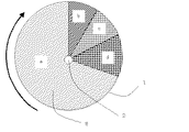
以下、図面を参照しながら本発明を更に詳しく説明する。図1は本発明に係るアンモニア回収装置の一構成例であり、吸着材を回転ロータに充填して排ガス中のアンモニアを連続的に回収する方法を示す概略説明図である。また図2には図1のアンモニア回収装置における回転ロータ部がA〜Dの各工程を回転により連続的に移行していくことを例示した。
次に、ブロア4によりアンモニアを含有する排ガスが吸引されロータ1に導入される。ロータ内にハニカム状吸着材8が充填されておりロータ回転軸2を中心としてロータ回転用モータ3により回転する。吸着材により排ガスに含まれるアンモニアは選択的に吸着除去され、処理ガスは系外にそのまま排出される。ロータ1は図2の矢印に示す方向に回転しており、上記の吸着工程Aは図のaに示す吸着ゾーンで実施され、回転するに従ってb〜dのゾーンにて工程B〜Dの処理が連続的に実施されていく。
【0030】
bの脱離ゾーンでは水蒸気が導入さ吸着していたアンモニアが脱離する工程Bとなり、水蒸気とアンモニアの混合ガスとして排出され冷却器5で冷却されアンモニア水として凝縮し、アンモニア水回収タンク6にアンモニアが回収される。またcの乾燥ゾーンでは工程Cとなり吸着材に付着した水分が追い出すために加熱した空気が導入され吸着材は乾燥される。さらにdの冷却ゾーンでは低温の空気を導入する工程Dとなり、これにより高温となった吸着材は冷却される。冷却されアンモニア吸着能力が再生された吸着材は再び吸着ゾーンaに移行して工程Aを実施する。この際、回収タンク6よりアンモニアを含むガスが一部パージされるが排ガスライン7をブロア1の入口部に繋ぐことによりアンモニアのリークは防止される。
【0031】
尚、図には示していないが、工程Bで排出される高温の蒸気を含むガスにより工程Cで吸着材を乾燥するガスを熱交換器を介して予熱することが好ましい。また工程Dで導入する冷却ガスとしては工程Aでアンモニアが吸着処理された後のガスを用いても良い。
【0032】
以下に参考例として、本発明に係る吸着剤、具体的には、TiおよびSiの二元系複合酸化物、Ti、Si及びZrの三元系複合酸化物について調製例を示すが、本発明の趣旨に反しない限り本発明に係る吸着剤の調製例は以下の調製方法に限定されるものではない。
【0033】
<TiおよびSiの二元系複合酸化物よりなる吸着材の調製例>
シリガゾル24kg(日産化学製NSC一30)に、アンモニア水280L(濃度25%)と水400Lを添加して溶液aを得た。一方、硫酸チタニルの硫酸水溶液153L(Ti O2濃度:250g/L、全硫酸濃度:1100g/L)を水300Lで希釈して溶液bを得た。次に、溶液aを攪拌しなから徐々に溶液bを滴下して共沈ゲルを生成し15時間静置した。得られたゲルを濾過、水洗後200℃で10時間乾燥し、550℃で6時間焼成してTiおよびSiからなる二元系複合酸化物を得た。得られた複合酸化物は、Ti/Si(モル比)=80/20、比表面積:160m2/gであった。以下、この二元系複合酸化物を「TS一1」と略記する。
【0034】
上記TS−1粉体に澱粉及び適当量の水を加えて混合しニ一ダで十分に混練した後、押出し成形機でハニカム形状に成形した。次いで、80℃で乾燥した後、450℃で2時間空気雰囲気にて焼成しハニカム成形体(目開き:2.1mm、肉厚:0.4mm)を得た。
【0035】
<TiおよびZrの二元系複合酸化物よりなる吸着材の調製例>
水1000Lにオキシ塩化ジルコニウム19.3kgを溶解させ、これと硫酸チタニルの硫酸水溶液78L(TiO2濃度:250g/L、全硫酸濃度:1100g/L)を混合して混合溶液を得た。次に、この混合溶液を攪拌しながらアンモニア水を徐々に滴下し、pHを7として共沈ゲルを生成し15時問静置した。得られたゲルを濾過、水洗後200℃で10時問乾燥し、450℃で6時間焼成してTiおよびZrからなる二元系複合酸化物を得た。得られた複合酸化物は、Ti/Zr(モル比)=80/20、比表面積:120m2/gであった。以下、この二元系複合酸化物を「TZ一1」と略記する。このようにして得られたTZ−1を上記TS−1と同様にしてハニカム成形体とした。
【0036】
<Ti、SiおよびZrの三元系複合酸化物よりなる吸着材の調製例>
TiおよびSiの二元系複合酸化物の調製例において、硫酸チタニルの代りに硫酸チタニルとオキシ塩化ジルコニウムの混合溶液を用いた以外は同様にして、Ti、SiおよびZrからなる三元系複合酸化物を得た。得られた複合酸化物は、Ti/Si/Zr(モル比)=80/16/4、比表面積:160m2/gであった。以下、この三元系複合酸化物を「TSZ−1」と略記する。このようにして得られたTSZ−1を前記TS−1と同様にしてハニカム成形体とした。
【0037】
【実施例】
図1及び図2に示すアンモニア回収装置を用いて排ガスに含まれるアンモニアを回収した。処理ガスはアンモニアガス濃度が300ppmであり10m3/minのガス量であった。吸着材0.2m3をロータに充填し、ロータの回転数を0.5rphとした。吸着材として上記調製例に示したチタン系複合酸化物よりなるハニカム状のものをロータに充填した。脱離する蒸気の温度は120℃なるように調整した。
【0038】
吸着処理された排ガスのアンモニア濃度及び回収されたアンモニア水の濃度を表1に示した。また参考のため吸着材としてハニカム状の活性炭あるいはゼオライトを用いた場合の結果も表1に合わせて示した。
【0039】
【表1】

表1の結果より本発明の方法によりコンパクトな装置を用いて排ガス中のアンモニアをアンモニア水として回収することが可能である。特に吸看材としてチタン系複合酸化物を用いることにより、従来の活性炭と比較して吸着能力が優れておりコンパクトな設備で排ガスを処理することが可能である。またチタン系複合酸化物は脱離特性が優れており比較的低温でアンモニアが脱離し高い濃度のアンモニア水を回収することができる。
【0041】
【発明の効果】
従来、アンモニアを処理するに際しては酸化により有害な窒素酸化物を生成したり、廃水として排出し閉鎖性海域の富栄養化により水質汚濁を招いたりすることが問題となっていたが、本発明の方法を用いることにより上記二次公害を発生することなく資源を有効的に利用することができる。すなわち本発明は以上の様に構成されており、簡易な装置を用いて排ガス中に含まれるアンモニアを効率的に吸着除去し、アンモニア水として回収することが可能である。
【図面の簡単な説明】
【図1】本発明の処理方法を実施する為に構成される回転ロータ式処理装置例の概略構成図である。
【図2】図1に示す処理装置における回転ロータの断面図を示す。
【符号の説明】
1 ロータ
2 ロータ回転軸
3 ロータ回転用モータ
4 ブロア
5 冷却器
6 アンモニア水回収タンク
7 排ガスライン
8 ハニカム状吸着材
a 吸着ゾーン
b 脱離ゾーン
c 乾燥ゾーン
d 冷却ゾーン[0001]
BACKGROUND OF THE INVENTION
The present invention relates to an ammonia recovery method for efficiently removing ammonia contained in exhaust gas with an adsorbent and recovering the adsorbed ammonia.
[0002]
[Prior art]
Ammonia is specified as a specific malodorous substance in the Malodor Control Law, and is expected to be contained in exhaust gas generated from various industrial fields. Various methods for treating such ammonia-containing exhaust gas have been proposed so far. For example, an adsorption method and a chemical cleaning method are known.
[0003]
In the above adsorption method, activated carbon is generally used as an adsorbent. However, since the adsorption capacity of this activated carbon for ammonia is very low, it is necessary to frequently replace the activated carbon, and post-treatment such as regeneration. The method becomes a problem. Ammonia can also be easily removed by the leaf liquid washing method or the water washing method, but the ammonia nitrogen in the generated wastewater is difficult to treat, and if it flows into the river or the sea, it is released into the atmosphere and emits odors. Water pollution due to eutrophication and eutrophication causes secondary pollution. In addition to these methods, direct combustion methods and catalytic combustion methods are also known, but these methods require heating the gas at all times, and are not preferable because of high fuel costs for treating low-concentration exhaust gases. .
[0004]
Under these circumstances, a method combining an adsorption method and a catalytic combustion method has been proposed as a low concentration and large capacity exhaust gas treatment method. This method usually adsorbs and removes harmful components with an adsorbent at room temperature, or adsorbs the adsorbent by heating the adsorbent at a stage where the adsorbed amount of the harmful component increases and the capacity of the adsorbent decreases. The adsorbent is regenerated by desorbing the harmful components that have been removed, and the desorbed harmful components are decomposed and removed by the combustion catalyst at the subsequent stage. In such a method, it is not necessary to always heat, and it is possible to significantly reduce the fuel cost by reducing the amount of gas at the time of desorption, increasing the concentration of desorbed gas, and generating reaction heat. In addition, the adsorbent can be used repeatedly and does not require frequent replacement.
[0005]
However, in such a method, activated carbon is generally used as an adsorbent, and as described above, this activated carbon has a low ammonia adsorption capacity, and is therefore not preferable because the frequency of regeneration increases. Therefore, it has been proposed to use zeolite as an adsorbent instead of activated carbon. However, since zeolite has a strong adsorbing power and cannot be desorbed and regenerated unless it is heated to about 500 ° C., it can be used as a zeolite with poor heat resistance. On the other hand, the adsorption capacity may be reduced by repeating the adsorption regeneration.
[0006]
On the other hand, it is expected that concentrated high-concentration ammonia is desorbed in the heat regeneration of the adsorbent. Since ammonia is oxidized in a high temperature atmosphere to produce harmful nitrogen oxides, the direct combustion method in which the gas is heated to 700 ° C. or higher is not suitable for the treatment of exhaust gas containing high concentration ammonia. Also, it is known that platinum-based catalysts generally used in catalytic combustion methods are easy to generate NOx by oxidizing ammonia. For example, in Japanese Patent Laid-Open No. 2-198638, a nickel metal oxide based catalyst of Ni, Mn, Cu, Fe is proposed for ammonia decomposition as an alternative to a platinum catalyst, but the activity at low temperature is insufficient. Or generation of N 2 O causing global warming is seen, which is not preferable. Japanese Patent Laid-Open No. 10-314548 proposes a method of treating nitrogen oxides formed by oxidizing a part of ammonia with a pre-stage catalyst by selective catalytic reduction with ammonia using a post-stage catalyst. Control is necessary, and it is not practical as an industrial method for treating a large amount of exhaust gas.
[0007]
[Problems to be solved by the invention]
The present invention has been made under such circumstances, and its object is to efficiently remove ammonia contained in exhaust gas with a compact facility without generating harmful nitrogen oxides, An object of the present invention is to provide an ammonia recovery method capable of reliably recovering ammonia in exhaust gas as ammonia water.
[0008]
[Means for Solving the Problems]
The ammonia recovery method of the present invention that has achieved the above-mentioned object is the method of adsorbing ammonia contained in exhaust gas using an adsorbent, step A, ammonia adsorbed in step A, and introducing ammonia into the adsorbent by introducing water vapor. The ammonia in the exhaust gas is recovered as ammonia water by the step B for desorbing the gas and the step E for cooling and condensing the gas containing the ammonia desorbed in the step B.
[0009]
Further, after desorbing ammonia in the above-mentioned step B, the step C for introducing and drying heated air to the adsorbent treated with water vapor, and the step D for introducing and cooling air to the dried adsorbent are sequentially performed. By doing so, the adsorbent can be regenerated and used again as an adsorbent.
[0010]
When carrying out the steps A to D, the exhaust gas can be continuously treated with a compact facility by filling the rotor with the adsorbent and rotating the rotor.
[0011]
Further, as the adsorbent, a binary composite oxide composed of Ti and Si having excellent adsorption / desorption characteristics of ammonia, a binary composite oxide composed of Ti and Zr, and a ternary system composed of Ti, Si and Zr It is preferable to use one containing at least one of complex oxides.
[0012]
DETAILED DESCRIPTION OF THE INVENTION
The present inventors have studied from various angles regarding a method for effectively treating ammonia contained in exhaust gas. As a result, it is possible to continuously process ammonia by performing the steps A to D using the adsorbent as described above, and the step E for cooling and condensing the gas generated in the step B is performed. Through this, it was found that it can be easily recovered as ammonia water, and the present invention was completed.
[0013]
In the ammonia recovery method of the present invention, the ammonia contained in the exhaust gas first comes into contact with the adsorbent in step A, and the exhaust gas from which ammonia has been adsorbed and removed is discharged out of the system. When the adsorption point of ammonia is saturated, ammonia leaks from the outlet of the adsorbent, so that the adsorbent can be regenerated by heating the adsorbent and desorbing ammonia before breakthrough.
[0014]
The ammonia adsorption capacity can be determined by measuring in advance the ammonia adsorption performance of the adsorbent used in the ammonia recovery method of the present invention. This makes it possible to determine the amount of adsorbent required according to the ammonia concentration in the exhaust gas and to predict the time for ammonia to leak from the outlet of the adsorbent. By replacing the adsorbent as appropriate before ammonia leaks, the ammonia in the exhaust gas can be treated continuously.
[0015]
In the ammonia recovery method of the present invention, the space velocity of the adsorbent with respect to the amount of processing gas is preferably 300 to 20000 hr −1 . In addition, the larger the ammonia adsorption capacity of the adsorbent, the higher the space velocity, and in order to obtain a more compact facility, the space velocity is preferably set to 1000 hr −1 or more.
[0016]
The present invention is applied to industrial exhaust gas containing ammonia at a high concentration generated in processes such as inorganic chemical manufacturing and semiconductor manufacturing using ammonia, and to medium-to-low concentration ammonia-containing exhaust gas generated from treatment facilities such as garbage and human waste processing facilities. Is possible. By adjusting the amount of adsorbent and the cycle time, the ammonia gas concentration contained in the exhaust gas can be processed to about 5 ppm to 20000 ppm.
[0017]
Next, by introducing water vapor into the adsorbent in the step B, the adsorbent is heated to desorb the adsorbed ammonia. The temperature of the water vapor is 110 ° C or higher, preferably 110 ° C to 140 ° C. If it is less than 110 ° C., the desorption of ammonia is insufficient, and the ammonia adsorption performance of the adsorbent is reduced.
[0018]
Next, in step C, heated air is introduced into the adsorbent that has been brought into a high humidity state by being treated with water vapor, and moisture is expelled to dry the adsorbent. As air for drying, normal atmospheric air can be used. The gas temperature of the drying gas is preferably 80 ° C. or higher, and more preferably 100 ° C. to 120 ° C. When the gas temperature is less than 80 ° C., it takes time to extrude moisture from the adsorbent, which is not preferable. As a heat source for increasing the temperature of the drying gas, it is economical to perform heat exchange using water vapor used in the step B.
[0019]
The regeneration process of the adsorbent can be achieved by the process D after the process C described above. In step D, the adsorbent is regenerated by introducing air into the adsorbent that has become high temperature and cooling it, and it becomes possible to efficiently remove ammonia in the exhaust gas again. As a cooling method for the adsorbent according to the step D, a normal cooling method can be used. Preferably, the temperature of air used for cooling is 40 ° C. or lower, and more preferably 30 ° C. or lower. This is because if the temperature of the air exceeds 40 ° C., the adsorbent is not sufficiently cooled, resulting in a decrease in the adsorption capacity and a predetermined performance cannot be obtained. By using the exhaust gas in which ammonia is adsorbed in step A as the air for cooling the adsorbent, a blower is not necessary.
[0020]
When ammonia-containing exhaust gas is continuously generated from the generation source, the above-described steps A to D are sequentially performed by filling the rotor with the above adsorbent and rotating the rotor, thereby continuously exhausting the exhaust gas with a compact facility. To recover ammonia. The rotor is divided into zones of steps A to D, and moves to the next step in order by rotating. Even in a batch system, by installing two adsorption towers, the adsorption process A and the regeneration processes B to D are alternately repeated in the two towers, whereby the exhaust gas containing ammonia can be continuously processed. Moreover, when ammonia exhaust gas does not generate | occur | produce continuously, it can respond with one tower. Compared with the batch method, the rotation method using a rotor can greatly reduce the amount of adsorbent to be filled.
[0021]
In step E of the ammonia recovery method of the present invention, in step E, the ammonia-containing gas desorbed in step B is recovered as ammonia water by step E for cooling and condensing. Since the ammonia gas is desorbed with water vapor, it can be cooled to ammonia water. The temperature for cooling the ammonia gas is 2 ° C to 30 ° C, preferably 5 ° C to 15 ° C.
As the adsorbent that can be used in the present invention, generally used activated carbon, zeolite, activated clay, silica alumina, silica gel, alumina, silica, titania, zirconia, acidic oxide, and the like can be used. In particular, as a preferable adsorbent for ammonia, any of binary complex oxides composed of Ti and Si, binary complex oxides composed of Ti and Zr, and ternary complex oxides composed of Ti, Si and Zr What contains 1 or more types is preferable. By making these into the form of complex oxides, effects that cannot be obtained with oxides of the constituent elements alone can be exhibited. That is, by using a single oxide of Ti, Si and Zr with a weak acidity and a low acid amount, or a binary composite oxide composed of Ti and Si or a binary oxide composed of Ti and Zr, It has been shown by Kozo Tabe ("Catalyst": Vol. 17, No. 3, p. 72, 1975) that a remarkable solid acidity is developed.
[0022]
Similarly, a ternary composite oxide composed of Ti, Si, and Zr also acts as a strong solid acid. Such solid acidity acts as an adsorption point for ammonia, which is a basic gas, and can give a remarkably high ammonia adsorption capacity as compared with generally used activated carbon. The exhaust gas may contain organic or inorganic gas components other than ammonia, but ammonia can be selectively adsorbed and removed by using the Ti-based composite oxide as an adsorbent. Yes, ammonia water with few impurities can be recovered.
The adsorbent may have various shapes such as powder, granule, sphere, column, plate and rod, but it is preferably a honeycomb having a large contact area and low pressure loss.
[0023]
In producing the titanium-based composite oxide as described above, the following may be performed. First, examples of the Ti source include inorganic titanium compounds such as titanium chloride and titanium sulfate, and organic titanium compounds such as titanium oxalate and tetraisoprovir titanate. Examples of the Si source include colloidal silica, water glass, and tetrachloride. Examples thereof include inorganic silicon compounds such as silicon, and organic silicon compounds such as tetraethyl silicate. Examples of the Zr source include inorganic zirconium compounds such as zirconium chloride and zirconium sulfate, and organic zirconium compounds such as zirconium acetate.
[0024]
The titanium-based composite oxide can be produced by a conventionally known method using the Ti source, the Si source, or the Zr source. For example, as a method for preparing a binary composite oxide composed of Ti and Si, the following methods (1) to (3) may be mentioned.
(1) A method in which titanium tetrachloride is mixed with silica sol, ammonia is added to form a precipitate, and this precipitate is washed and dried and then burned.
(2) A method in which an aqueous sodium silicate solution (water glass) is added to titanium tetrachloride to form a precipitate (coprecipitate), which is washed and dried and then fired.
(3) A method in which tetraethyl silicate is added to a water-alcohol solution of titanium tetrachloride to form a precipitate by hydrolysis, which is washed, dried and then fired.
[0025]
In each of the above methods, a binary composite oxide composed of Ti and Si can be easily obtained by firing the coprecipitate at 300 to 650 ° C. for 1 to 10 hours. Similarly, a binary or ternary composite oxide can be obtained by appropriately adjusting the molar ratio of Ti source and Si source or Ti source, Si source and Zr source.
[0026]
The titanium-based composite oxide as described above preferably has a Ti content of 20 to 95 mol%, more preferably 50 to 85 mol%. When the Ti content is less than 20 mol% or exceeds 95 mol%, it is difficult to obtain a preferable effect of the composite oxide. The titanium-based composite oxide thus obtained has a high specific surface area of 100 m 2 / g or more and has excellent heat resistance. Therefore, by repeatedly using an adsorbent composed of this composite oxide. Since the adsorption capacity hardly decreases, it can be used for a long time. From the viewpoint of obtaining a porous and high surface area composite oxide, the adsorbent preferably contains a binary composite oxide of Ti and Si.
[0027]
These titanium-based composite oxides have excellent formability and can be formed into a predetermined shape by pressure molding or extrusion molding. However, the honeycomb-shaped composite oxide has a low pressure loss and a high contact efficiency with gas. preferable.
[0028]
In addition to the Ti-based complex oxide, the adsorbent may contain 0 to 20% by mass of an oxide selected from V, W, and Mo. In particular, by adding V, it is possible to remarkably improve the ammonia adsorption performance.
[0029]
Hereinafter, the present invention will be described in more detail with reference to the drawings. FIG. 1 is an example of a configuration of an ammonia recovery apparatus according to the present invention, and is a schematic explanatory view showing a method for continuously recovering ammonia in exhaust gas by filling an adsorbent into a rotary rotor. FIG. 2 exemplifies that the rotating rotor portion in the ammonia recovery apparatus of FIG. 1 continuously shifts the steps A to D by rotation.
Next, exhaust gas containing ammonia is sucked by the blower 4 and introduced into the
[0030]
In the desorption zone b, ammonia is introduced and adsorbed by the water vapor, so that the process B is performed. The ammonia is discharged as a mixed gas of water vapor and ammonia, cooled by the cooler 5 and condensed as ammonia water. Ammonia is recovered. Further, in the drying zone c, the process becomes step C, and heated air is introduced to expel moisture adhering to the adsorbent, and the adsorbent is dried. Furthermore, in the cooling zone d, it becomes a process D for introducing low-temperature air, whereby the adsorbent having a high temperature is cooled. The adsorbent, which has been cooled and regenerated with its ammonia adsorption capacity, again moves to the adsorption zone a and performs step A. At this time, a part of the gas containing ammonia is purged from the recovery tank 6, but ammonia leakage is prevented by connecting the exhaust gas line 7 to the inlet of the
[0031]
Although not shown in the figure, it is preferable to preheat the gas for drying the adsorbent in step C with a gas containing high-temperature steam discharged in step B via a heat exchanger. Further, as the cooling gas introduced in the step D, a gas after the ammonia is adsorbed in the step A may be used.
[0032]
As reference examples, preparation examples of adsorbents according to the present invention, specifically, binary composite oxides of Ti and Si, and ternary composite oxides of Ti, Si, and Zr are shown below. Unless it is contrary to the meaning, the preparation examples of the adsorbent according to the present invention are not limited to the following preparation methods.
[0033]
<Preparation example of adsorbent made of binary composite oxide of Ti and Si>
A solution a was obtained by adding 280 L of ammonia water (concentration 25%) and 400 L of water to 24 kg of ciligazol (NSC 30 manufactured by Nissan Chemical Co., Ltd.). On the other hand, 153 L of a sulfuric acid aqueous solution of titanyl sulfate (TiO 2 concentration: 250 g / L, total sulfuric acid concentration: 1100 g / L) was diluted with 300 L of water to obtain a solution b. Next, since the solution a was not stirred, the solution b was gradually added dropwise to form a coprecipitated gel, which was allowed to stand for 15 hours. The obtained gel was filtered, washed with water, dried at 200 ° C. for 10 hours, and calcined at 550 ° C. for 6 hours to obtain a binary composite oxide composed of Ti and Si. The obtained composite oxide had Ti / Si (molar ratio) = 80/20 and specific surface area: 160 m 2 / g. Hereinafter, this binary composite oxide is abbreviated as “TS-1”.
[0034]
Starch and an appropriate amount of water were added to the TS-1 powder, mixed and sufficiently kneaded with a kneader, and then formed into a honeycomb shape with an extruder. Next, after drying at 80 ° C., firing was performed in an air atmosphere at 450 ° C. for 2 hours to obtain a honeycomb formed body (aperture: 2.1 mm, wall thickness: 0.4 mm).
[0035]
<Preparation example of adsorbent made of binary composite oxide of Ti and Zr>
19.3 kg of zirconium oxychloride was dissolved in 1000 L of water, and this was mixed with 78 L of sulfuric acid aqueous solution of titanyl sulfate (TiO 2 concentration: 250 g / L, total sulfuric acid concentration: 1100 g / L) to obtain a mixed solution. Next, while stirring this mixed solution, ammonia water was gradually added dropwise to produce a coprecipitated gel with a pH of 7, and allowed to stand for 15:00. The gel obtained was filtered, washed with water, dried at 200 ° C. for 10 hours, and calcined at 450 ° C. for 6 hours to obtain a binary composite oxide composed of Ti and Zr. The obtained composite oxide had Ti / Zr (molar ratio) = 80/20 and specific surface area: 120 m 2 / g. Hereinafter, this binary complex oxide is abbreviated as “TZ-1”. The TZ-1 thus obtained was made into a honeycomb formed body in the same manner as TS-1.
[0036]
<Preparation example of adsorbent made of ternary composite oxide of Ti, Si and Zr>
In the preparation example of binary complex oxides of Ti and Si, a ternary complex oxidation consisting of Ti, Si and Zr was similarly performed except that a mixed solution of titanyl sulfate and zirconium oxychloride was used instead of titanyl sulfate. I got a thing. The obtained composite oxide was Ti / Si / Zr (molar ratio) = 80/16/4 and specific surface area: 160 m 2 / g. Hereinafter, this ternary composite oxide is abbreviated as “TSZ-1”. TSZ-1 obtained in this way was formed into a honeycomb formed body in the same manner as TS-1.
[0037]
【Example】
The ammonia contained in the exhaust gas was recovered using the ammonia recovery apparatus shown in FIGS. The treatment gas had an ammonia gas concentration of 300 ppm and a gas amount of 10 m 3 / min. The adsorbent 0.2 m 3 was charged into the rotor, the rotational speed of the rotor was 0.5Rph. The rotor was filled with a honeycomb-like material made of the titanium-based composite oxide shown in the above preparation example as an adsorbent. The temperature of the desorbed vapor was adjusted to 120 ° C.
[0038]
Table 1 shows the ammonia concentration of the exhaust gas subjected to the adsorption treatment and the concentration of the recovered ammonia water. For reference, the results when honeycomb activated carbon or zeolite is used as the adsorbent are also shown in Table 1.
[0039]
[Table 1]
From the results shown in Table 1, it is possible to recover ammonia in the exhaust gas as ammonia water using a compact apparatus by the method of the present invention. In particular, by using a titanium-based composite oxide as an absorbent material, the adsorption capacity is superior to that of conventional activated carbon, and it is possible to treat exhaust gas with a compact facility. In addition, the titanium-based composite oxide has excellent desorption characteristics, and ammonia can be desorbed at a relatively low temperature to recover a high concentration of ammonia water.
[0041]
【The invention's effect】
Conventionally, when ammonia is treated, harmful nitrogen oxides are generated by oxidation, or discharged as waste water, causing water pollution due to eutrophication in closed sea areas. By using the method, it is possible to effectively use resources without generating the secondary pollution. That is, the present invention is configured as described above, and it is possible to efficiently adsorb and remove ammonia contained in the exhaust gas using a simple device and recover it as ammonia water.
[Brief description of the drawings]
FIG. 1 is a schematic configuration diagram of an example of a rotary rotor type processing apparatus configured to perform a processing method of the present invention.
FIG. 2 is a cross-sectional view of a rotating rotor in the processing apparatus shown in FIG.
[Explanation of symbols]
DESCRIPTION OF
Claims (4)
Priority Applications (1)
| Application Number | Priority Date | Filing Date | Title |
|---|---|---|---|
| JP2001295235A JP3880353B2 (en) | 2001-09-27 | 2001-09-27 | Ammonia recovery method |
Applications Claiming Priority (1)
| Application Number | Priority Date | Filing Date | Title |
|---|---|---|---|
| JP2001295235A JP3880353B2 (en) | 2001-09-27 | 2001-09-27 | Ammonia recovery method |
Publications (2)
| Publication Number | Publication Date |
|---|---|
| JP2003095644A JP2003095644A (en) | 2003-04-03 |
| JP3880353B2 true JP3880353B2 (en) | 2007-02-14 |
Family
ID=19116702
Family Applications (1)
| Application Number | Title | Priority Date | Filing Date |
|---|---|---|---|
| JP2001295235A Expired - Fee Related JP3880353B2 (en) | 2001-09-27 | 2001-09-27 | Ammonia recovery method |
Country Status (1)
| Country | Link |
|---|---|
| JP (1) | JP3880353B2 (en) |
Families Citing this family (11)
| Publication number | Priority date | Publication date | Assignee | Title |
|---|---|---|---|---|
| JP2005238044A (en) * | 2004-02-25 | 2005-09-08 | Toyobo Co Ltd | System for treating basic gas |
| US7767163B2 (en) * | 2004-04-20 | 2010-08-03 | Umicore Ag & Co. Kg | Exhaust treatment devices |
| JP2009052753A (en) * | 2007-08-23 | 2009-03-12 | Seibu Giken Co Ltd | Ventilation fan |
| JP2010201357A (en) * | 2009-03-04 | 2010-09-16 | Central Res Inst Of Electric Power Ind | Method of treating used adsorbent |
| JP5927074B2 (en) * | 2012-07-24 | 2016-05-25 | 国立大学法人岐阜大学 | Gas processing method and gas processing apparatus |
| KR101785505B1 (en) * | 2015-03-27 | 2017-10-17 | (주) 에코데이 | Apparatus for removal and recovery of high concentration nitrogen and phosphorus using ammonia stripping |
| JP6516003B2 (en) * | 2015-05-28 | 2019-05-22 | 東洋紡株式会社 | Adsorption processing unit |
| KR101902776B1 (en) * | 2016-09-26 | 2018-10-01 | (주)원익머트리얼즈 | Apparatus for absorbing ammonia gas |
| KR101908721B1 (en) * | 2016-11-11 | 2018-10-18 | 대한민국 | Reactor of liquefied ammonia recovery |
| JP7209994B2 (en) * | 2018-06-13 | 2023-01-23 | 国立研究開発法人産業技術総合研究所 | Ammonia desorption method, ammonia recovery method, and ammonia recovery device |
| CN110052148A (en) * | 2019-06-03 | 2019-07-26 | 东北农业大学 | One kind cold ground winter poultry house outlet ammonia processing method |
-
2001
- 2001-09-27 JP JP2001295235A patent/JP3880353B2/en not_active Expired - Fee Related
Also Published As
| Publication number | Publication date |
|---|---|
| JP2003095644A (en) | 2003-04-03 |
Similar Documents
| Publication | Publication Date | Title |
|---|---|---|
| JP3589529B2 (en) | Method and apparatus for treating flue gas | |
| JP5140277B2 (en) | Cement kiln flue gas treatment method | |
| JP3880353B2 (en) | Ammonia recovery method | |
| JP3272367B2 (en) | Heat-treated activated carbon fiber for denitration, method for producing the same, denitration method using the same, and denitration system using the same | |
| JPH0663357A (en) | Device for treating waste gas containing organic halogen compounds | |
| CN106807177A (en) | The gas cleaning plant and purification method of a kind of removing VOCs | |
| CN104888806A (en) | Regeneration method for inactivated TiV-based honeycomb denitration catalyst having combined denitration and demercuration modification function | |
| JP3655802B2 (en) | Waste water treatment method and waste water treatment apparatus using the method | |
| CN205850524U (en) | Catalytic combustion system after waste gas Adsorption Concentration | |
| JP4113090B2 (en) | Exhaust gas treatment method | |
| JP5810488B2 (en) | Wastewater treatment system | |
| CN111372669A (en) | Energy-saving concentrated rotor reaches exhaust treatment system including it | |
| JPH09225301A (en) | Method for purifying fumigation exhaust gas and catalyst therefor | |
| JP2002321912A (en) | Zeolite for absorption and device for removing gas using the same | |
| JP3457953B2 (en) | Nitrogen oxide and / or sulfur oxide adsorbent | |
| JP3535801B2 (en) | Treatment method for exhaust gas containing basic gas | |
| JP2002248317A (en) | Method for removing malodorous substance and deodorization facility | |
| JP2001079346A (en) | Method and device for treating gas and method for regenerating honeycomb activated carbon | |
| CN205832973U (en) | A kind of integral type VOCs Adsorption Concentration catalyzing oxidizing degrading rotary wheel device | |
| JP5861547B2 (en) | Wastewater treatment system | |
| CN110701621A (en) | Conditioning agent for waste incineration and method for controlling emission reduction of flue gas mercury and nitrogen oxide by conditioning agent | |
| JP4876644B2 (en) | Exhaust gas purification method | |
| JP3785296B2 (en) | Catalyst regeneration method | |
| JPH0523590A (en) | Catalyst for decomposing ozone | |
| JP3318607B2 (en) | New selective NH3 deodorization method |
Legal Events
| Date | Code | Title | Description |
|---|---|---|---|
| A977 | Report on retrieval |
Free format text: JAPANESE INTERMEDIATE CODE: A971007 Effective date: 20051026 |
|
| A131 | Notification of reasons for refusal |
Free format text: JAPANESE INTERMEDIATE CODE: A131 Effective date: 20060725 |
|
| TRDD | Decision of grant or rejection written | ||
| A01 | Written decision to grant a patent or to grant a registration (utility model) |
Free format text: JAPANESE INTERMEDIATE CODE: A01 Effective date: 20061017 |
|
| A61 | First payment of annual fees (during grant procedure) |
Free format text: JAPANESE INTERMEDIATE CODE: A61 Effective date: 20061107 |
|
| R150 | Certificate of patent or registration of utility model |
Free format text: JAPANESE INTERMEDIATE CODE: R150 |
|
| LAPS | Cancellation because of no payment of annual fees |