JP3879055B2 - Electrosurgical sphincter treatment instrument - Google Patents
Electrosurgical sphincter treatment instrument Download PDFInfo
- Publication number
- JP3879055B2 JP3879055B2 JP2000532065A JP2000532065A JP3879055B2 JP 3879055 B2 JP3879055 B2 JP 3879055B2 JP 2000532065 A JP2000532065 A JP 2000532065A JP 2000532065 A JP2000532065 A JP 2000532065A JP 3879055 B2 JP3879055 B2 JP 3879055B2
- Authority
- JP
- Japan
- Prior art keywords
- sphincter
- electrode
- tissue
- fluid
- instrument
- Prior art date
- Legal status (The legal status is an assumption and is not a legal conclusion. Google has not performed a legal analysis and makes no representation as to the accuracy of the status listed.)
- Expired - Fee Related
Links
Images


Classifications
-
- A—HUMAN NECESSITIES
- A61—MEDICAL OR VETERINARY SCIENCE; HYGIENE
- A61B—DIAGNOSIS; SURGERY; IDENTIFICATION
- A61B18/00—Surgical instruments, devices or methods for transferring non-mechanical forms of energy to or from the body
- A61B18/04—Surgical instruments, devices or methods for transferring non-mechanical forms of energy to or from the body by heating
- A61B18/12—Surgical instruments, devices or methods for transferring non-mechanical forms of energy to or from the body by heating by passing a current through the tissue to be heated, e.g. high-frequency current
- A61B18/1206—Generators therefor
-
- A—HUMAN NECESSITIES
- A61—MEDICAL OR VETERINARY SCIENCE; HYGIENE
- A61B—DIAGNOSIS; SURGERY; IDENTIFICATION
- A61B18/00—Surgical instruments, devices or methods for transferring non-mechanical forms of energy to or from the body
- A61B18/04—Surgical instruments, devices or methods for transferring non-mechanical forms of energy to or from the body by heating
- A61B18/12—Surgical instruments, devices or methods for transferring non-mechanical forms of energy to or from the body by heating by passing a current through the tissue to be heated, e.g. high-frequency current
- A61B18/14—Probes or electrodes therefor
- A61B18/1477—Needle-like probes
-
- A—HUMAN NECESSITIES
- A61—MEDICAL OR VETERINARY SCIENCE; HYGIENE
- A61B—DIAGNOSIS; SURGERY; IDENTIFICATION
- A61B18/00—Surgical instruments, devices or methods for transferring non-mechanical forms of energy to or from the body
- A61B18/04—Surgical instruments, devices or methods for transferring non-mechanical forms of energy to or from the body by heating
- A61B18/12—Surgical instruments, devices or methods for transferring non-mechanical forms of energy to or from the body by heating by passing a current through the tissue to be heated, e.g. high-frequency current
- A61B18/14—Probes or electrodes therefor
- A61B18/148—Probes or electrodes therefor having a short, rigid shaft for accessing the inner body transcutaneously, e.g. for neurosurgery or arthroscopy
-
- A—HUMAN NECESSITIES
- A61—MEDICAL OR VETERINARY SCIENCE; HYGIENE
- A61B—DIAGNOSIS; SURGERY; IDENTIFICATION
- A61B18/00—Surgical instruments, devices or methods for transferring non-mechanical forms of energy to or from the body
- A61B18/04—Surgical instruments, devices or methods for transferring non-mechanical forms of energy to or from the body by heating
- A61B18/12—Surgical instruments, devices or methods for transferring non-mechanical forms of energy to or from the body by heating by passing a current through the tissue to be heated, e.g. high-frequency current
- A61B18/14—Probes or electrodes therefor
- A61B18/1485—Probes or electrodes therefor having a short rigid shaft for accessing the inner body through natural openings
-
- A—HUMAN NECESSITIES
- A61—MEDICAL OR VETERINARY SCIENCE; HYGIENE
- A61B—DIAGNOSIS; SURGERY; IDENTIFICATION
- A61B18/00—Surgical instruments, devices or methods for transferring non-mechanical forms of energy to or from the body
- A61B18/04—Surgical instruments, devices or methods for transferring non-mechanical forms of energy to or from the body by heating
- A61B18/12—Surgical instruments, devices or methods for transferring non-mechanical forms of energy to or from the body by heating by passing a current through the tissue to be heated, e.g. high-frequency current
- A61B18/14—Probes or electrodes therefor
- A61B18/1492—Probes or electrodes therefor having a flexible, catheter-like structure, e.g. for heart ablation
-
- A—HUMAN NECESSITIES
- A61—MEDICAL OR VETERINARY SCIENCE; HYGIENE
- A61B—DIAGNOSIS; SURGERY; IDENTIFICATION
- A61B18/00—Surgical instruments, devices or methods for transferring non-mechanical forms of energy to or from the body
- A61B18/18—Surgical instruments, devices or methods for transferring non-mechanical forms of energy to or from the body by applying electromagnetic radiation, e.g. microwaves
-
- A—HUMAN NECESSITIES
- A61—MEDICAL OR VETERINARY SCIENCE; HYGIENE
- A61M—DEVICES FOR INTRODUCING MEDIA INTO, OR ONTO, THE BODY; DEVICES FOR TRANSDUCING BODY MEDIA OR FOR TAKING MEDIA FROM THE BODY; DEVICES FOR PRODUCING OR ENDING SLEEP OR STUPOR
- A61M16/00—Devices for influencing the respiratory system of patients by gas treatment, e.g. mouth-to-mouth respiration; Tracheal tubes
- A61M16/04—Tracheal tubes
- A61M16/0434—Cuffs
- A61M16/0436—Special fillings therefor
- A61M16/0438—Liquid-filled
-
- A—HUMAN NECESSITIES
- A61—MEDICAL OR VETERINARY SCIENCE; HYGIENE
- A61M—DEVICES FOR INTRODUCING MEDIA INTO, OR ONTO, THE BODY; DEVICES FOR TRANSDUCING BODY MEDIA OR FOR TAKING MEDIA FROM THE BODY; DEVICES FOR PRODUCING OR ENDING SLEEP OR STUPOR
- A61M16/00—Devices for influencing the respiratory system of patients by gas treatment, e.g. mouth-to-mouth respiration; Tracheal tubes
- A61M16/04—Tracheal tubes
- A61M16/0475—Tracheal tubes having openings in the tube
- A61M16/0477—Tracheal tubes having openings in the tube with incorporated means for delivering or removing fluids
- A61M16/0481—Tracheal tubes having openings in the tube with incorporated means for delivering or removing fluids through the cuff wall
-
- A—HUMAN NECESSITIES
- A61—MEDICAL OR VETERINARY SCIENCE; HYGIENE
- A61N—ELECTROTHERAPY; MAGNETOTHERAPY; RADIATION THERAPY; ULTRASOUND THERAPY
- A61N1/00—Electrotherapy; Circuits therefor
- A61N1/02—Details
- A61N1/04—Electrodes
- A61N1/05—Electrodes for implantation or insertion into the body, e.g. heart electrode
- A61N1/056—Transvascular endocardial electrode systems
-
- A—HUMAN NECESSITIES
- A61—MEDICAL OR VETERINARY SCIENCE; HYGIENE
- A61N—ELECTROTHERAPY; MAGNETOTHERAPY; RADIATION THERAPY; ULTRASOUND THERAPY
- A61N1/00—Electrotherapy; Circuits therefor
- A61N1/02—Details
- A61N1/04—Electrodes
- A61N1/06—Electrodes for high-frequency therapy
-
- A—HUMAN NECESSITIES
- A61—MEDICAL OR VETERINARY SCIENCE; HYGIENE
- A61N—ELECTROTHERAPY; MAGNETOTHERAPY; RADIATION THERAPY; ULTRASOUND THERAPY
- A61N1/00—Electrotherapy; Circuits therefor
- A61N1/40—Applying electric fields by inductive or capacitive coupling ; Applying radio-frequency signals
-
- A—HUMAN NECESSITIES
- A61—MEDICAL OR VETERINARY SCIENCE; HYGIENE
- A61B—DIAGNOSIS; SURGERY; IDENTIFICATION
- A61B17/00—Surgical instruments, devices or methods, e.g. tourniquets
- A61B17/32—Surgical cutting instruments
-
- A—HUMAN NECESSITIES
- A61—MEDICAL OR VETERINARY SCIENCE; HYGIENE
- A61B—DIAGNOSIS; SURGERY; IDENTIFICATION
- A61B18/00—Surgical instruments, devices or methods for transferring non-mechanical forms of energy to or from the body
- A61B18/18—Surgical instruments, devices or methods for transferring non-mechanical forms of energy to or from the body by applying electromagnetic radiation, e.g. microwaves
- A61B18/1815—Surgical instruments, devices or methods for transferring non-mechanical forms of energy to or from the body by applying electromagnetic radiation, e.g. microwaves using microwaves
-
- A—HUMAN NECESSITIES
- A61—MEDICAL OR VETERINARY SCIENCE; HYGIENE
- A61B—DIAGNOSIS; SURGERY; IDENTIFICATION
- A61B17/00—Surgical instruments, devices or methods, e.g. tourniquets
- A61B2017/00017—Electrical control of surgical instruments
- A61B2017/00022—Sensing or detecting at the treatment site
- A61B2017/00084—Temperature
-
- A—HUMAN NECESSITIES
- A61—MEDICAL OR VETERINARY SCIENCE; HYGIENE
- A61B—DIAGNOSIS; SURGERY; IDENTIFICATION
- A61B17/00—Surgical instruments, devices or methods, e.g. tourniquets
- A61B2017/00017—Electrical control of surgical instruments
- A61B2017/00022—Sensing or detecting at the treatment site
- A61B2017/00106—Sensing or detecting at the treatment site ultrasonic
-
- A—HUMAN NECESSITIES
- A61—MEDICAL OR VETERINARY SCIENCE; HYGIENE
- A61B—DIAGNOSIS; SURGERY; IDENTIFICATION
- A61B17/00—Surgical instruments, devices or methods, e.g. tourniquets
- A61B17/00234—Surgical instruments, devices or methods, e.g. tourniquets for minimally invasive surgery
- A61B2017/00292—Surgical instruments, devices or methods, e.g. tourniquets for minimally invasive surgery mounted on or guided by flexible, e.g. catheter-like, means
- A61B2017/003—Steerable
-
- A—HUMAN NECESSITIES
- A61—MEDICAL OR VETERINARY SCIENCE; HYGIENE
- A61B—DIAGNOSIS; SURGERY; IDENTIFICATION
- A61B17/00—Surgical instruments, devices or methods, e.g. tourniquets
- A61B17/22—Implements for squeezing-off ulcers or the like on the inside of inner organs of the body; Implements for scraping-out cavities of body organs, e.g. bones; Calculus removers; Calculus smashing apparatus; Apparatus for removing obstructions in blood vessels, not otherwise provided for
- A61B2017/22051—Implements for squeezing-off ulcers or the like on the inside of inner organs of the body; Implements for scraping-out cavities of body organs, e.g. bones; Calculus removers; Calculus smashing apparatus; Apparatus for removing obstructions in blood vessels, not otherwise provided for with an inflatable part, e.g. balloon, for positioning, blocking, or immobilisation
- A61B2017/22061—Implements for squeezing-off ulcers or the like on the inside of inner organs of the body; Implements for scraping-out cavities of body organs, e.g. bones; Calculus removers; Calculus smashing apparatus; Apparatus for removing obstructions in blood vessels, not otherwise provided for with an inflatable part, e.g. balloon, for positioning, blocking, or immobilisation for spreading elements apart
-
- A—HUMAN NECESSITIES
- A61—MEDICAL OR VETERINARY SCIENCE; HYGIENE
- A61B—DIAGNOSIS; SURGERY; IDENTIFICATION
- A61B17/00—Surgical instruments, devices or methods, e.g. tourniquets
- A61B17/42—Gynaecological or obstetrical instruments or methods
- A61B2017/4216—Operations on uterus, e.g. endometrium
-
- A—HUMAN NECESSITIES
- A61—MEDICAL OR VETERINARY SCIENCE; HYGIENE
- A61B—DIAGNOSIS; SURGERY; IDENTIFICATION
- A61B18/00—Surgical instruments, devices or methods for transferring non-mechanical forms of energy to or from the body
- A61B2018/00005—Cooling or heating of the probe or tissue immediately surrounding the probe
- A61B2018/00011—Cooling or heating of the probe or tissue immediately surrounding the probe with fluids
- A61B2018/00023—Cooling or heating of the probe or tissue immediately surrounding the probe with fluids closed, i.e. without wound contact by the fluid
-
- A—HUMAN NECESSITIES
- A61—MEDICAL OR VETERINARY SCIENCE; HYGIENE
- A61B—DIAGNOSIS; SURGERY; IDENTIFICATION
- A61B18/00—Surgical instruments, devices or methods for transferring non-mechanical forms of energy to or from the body
- A61B2018/00005—Cooling or heating of the probe or tissue immediately surrounding the probe
- A61B2018/00011—Cooling or heating of the probe or tissue immediately surrounding the probe with fluids
- A61B2018/00029—Cooling or heating of the probe or tissue immediately surrounding the probe with fluids open
-
- A—HUMAN NECESSITIES
- A61—MEDICAL OR VETERINARY SCIENCE; HYGIENE
- A61B—DIAGNOSIS; SURGERY; IDENTIFICATION
- A61B18/00—Surgical instruments, devices or methods for transferring non-mechanical forms of energy to or from the body
- A61B2018/00053—Mechanical features of the instrument of device
- A61B2018/00059—Material properties
- A61B2018/00065—Material properties porous
-
- A—HUMAN NECESSITIES
- A61—MEDICAL OR VETERINARY SCIENCE; HYGIENE
- A61B—DIAGNOSIS; SURGERY; IDENTIFICATION
- A61B18/00—Surgical instruments, devices or methods for transferring non-mechanical forms of energy to or from the body
- A61B2018/00053—Mechanical features of the instrument of device
- A61B2018/00059—Material properties
- A61B2018/00071—Electrical conductivity
- A61B2018/00077—Electrical conductivity high, i.e. electrically conducting
-
- A—HUMAN NECESSITIES
- A61—MEDICAL OR VETERINARY SCIENCE; HYGIENE
- A61B—DIAGNOSIS; SURGERY; IDENTIFICATION
- A61B18/00—Surgical instruments, devices or methods for transferring non-mechanical forms of energy to or from the body
- A61B2018/00053—Mechanical features of the instrument of device
- A61B2018/00059—Material properties
- A61B2018/00071—Electrical conductivity
- A61B2018/00083—Electrical conductivity low, i.e. electrically insulating
-
- A—HUMAN NECESSITIES
- A61—MEDICAL OR VETERINARY SCIENCE; HYGIENE
- A61B—DIAGNOSIS; SURGERY; IDENTIFICATION
- A61B18/00—Surgical instruments, devices or methods for transferring non-mechanical forms of energy to or from the body
- A61B2018/00053—Mechanical features of the instrument of device
- A61B2018/00107—Coatings on the energy applicator
- A61B2018/00113—Coatings on the energy applicator with foam
-
- A—HUMAN NECESSITIES
- A61—MEDICAL OR VETERINARY SCIENCE; HYGIENE
- A61B—DIAGNOSIS; SURGERY; IDENTIFICATION
- A61B18/00—Surgical instruments, devices or methods for transferring non-mechanical forms of energy to or from the body
- A61B2018/00053—Mechanical features of the instrument of device
- A61B2018/00107—Coatings on the energy applicator
- A61B2018/00148—Coatings on the energy applicator with metal
-
- A—HUMAN NECESSITIES
- A61—MEDICAL OR VETERINARY SCIENCE; HYGIENE
- A61B—DIAGNOSIS; SURGERY; IDENTIFICATION
- A61B18/00—Surgical instruments, devices or methods for transferring non-mechanical forms of energy to or from the body
- A61B2018/00053—Mechanical features of the instrument of device
- A61B2018/0016—Energy applicators arranged in a two- or three dimensional array
-
- A—HUMAN NECESSITIES
- A61—MEDICAL OR VETERINARY SCIENCE; HYGIENE
- A61B—DIAGNOSIS; SURGERY; IDENTIFICATION
- A61B18/00—Surgical instruments, devices or methods for transferring non-mechanical forms of energy to or from the body
- A61B2018/00053—Mechanical features of the instrument of device
- A61B2018/00214—Expandable means emitting energy, e.g. by elements carried thereon
- A61B2018/0022—Balloons
-
- A—HUMAN NECESSITIES
- A61—MEDICAL OR VETERINARY SCIENCE; HYGIENE
- A61B—DIAGNOSIS; SURGERY; IDENTIFICATION
- A61B18/00—Surgical instruments, devices or methods for transferring non-mechanical forms of energy to or from the body
- A61B2018/00053—Mechanical features of the instrument of device
- A61B2018/00214—Expandable means emitting energy, e.g. by elements carried thereon
- A61B2018/00267—Expandable means emitting energy, e.g. by elements carried thereon having a basket shaped structure
-
- A—HUMAN NECESSITIES
- A61—MEDICAL OR VETERINARY SCIENCE; HYGIENE
- A61B—DIAGNOSIS; SURGERY; IDENTIFICATION
- A61B18/00—Surgical instruments, devices or methods for transferring non-mechanical forms of energy to or from the body
- A61B2018/00315—Surgical instruments, devices or methods for transferring non-mechanical forms of energy to or from the body for treatment of particular body parts
- A61B2018/00482—Digestive system
- A61B2018/00488—Esophagus
-
- A—HUMAN NECESSITIES
- A61—MEDICAL OR VETERINARY SCIENCE; HYGIENE
- A61B—DIAGNOSIS; SURGERY; IDENTIFICATION
- A61B18/00—Surgical instruments, devices or methods for transferring non-mechanical forms of energy to or from the body
- A61B2018/00315—Surgical instruments, devices or methods for transferring non-mechanical forms of energy to or from the body for treatment of particular body parts
- A61B2018/00482—Digestive system
- A61B2018/00494—Stomach, intestines or bowel
-
- A—HUMAN NECESSITIES
- A61—MEDICAL OR VETERINARY SCIENCE; HYGIENE
- A61B—DIAGNOSIS; SURGERY; IDENTIFICATION
- A61B18/00—Surgical instruments, devices or methods for transferring non-mechanical forms of energy to or from the body
- A61B2018/00315—Surgical instruments, devices or methods for transferring non-mechanical forms of energy to or from the body for treatment of particular body parts
- A61B2018/00553—Sphincter
-
- A—HUMAN NECESSITIES
- A61—MEDICAL OR VETERINARY SCIENCE; HYGIENE
- A61B—DIAGNOSIS; SURGERY; IDENTIFICATION
- A61B18/00—Surgical instruments, devices or methods for transferring non-mechanical forms of energy to or from the body
- A61B2018/00571—Surgical instruments, devices or methods for transferring non-mechanical forms of energy to or from the body for achieving a particular surgical effect
- A61B2018/00577—Ablation
-
- A—HUMAN NECESSITIES
- A61—MEDICAL OR VETERINARY SCIENCE; HYGIENE
- A61B—DIAGNOSIS; SURGERY; IDENTIFICATION
- A61B18/00—Surgical instruments, devices or methods for transferring non-mechanical forms of energy to or from the body
- A61B2018/00636—Sensing and controlling the application of energy
- A61B2018/00642—Sensing and controlling the application of energy with feedback, i.e. closed loop control
- A61B2018/00648—Sensing and controlling the application of energy with feedback, i.e. closed loop control using more than one sensed parameter
-
- A—HUMAN NECESSITIES
- A61—MEDICAL OR VETERINARY SCIENCE; HYGIENE
- A61B—DIAGNOSIS; SURGERY; IDENTIFICATION
- A61B18/00—Surgical instruments, devices or methods for transferring non-mechanical forms of energy to or from the body
- A61B2018/00636—Sensing and controlling the application of energy
- A61B2018/00642—Sensing and controlling the application of energy with feedback, i.e. closed loop control
- A61B2018/00654—Sensing and controlling the application of energy with feedback, i.e. closed loop control with individual control of each of a plurality of energy emitting elements
-
- A—HUMAN NECESSITIES
- A61—MEDICAL OR VETERINARY SCIENCE; HYGIENE
- A61B—DIAGNOSIS; SURGERY; IDENTIFICATION
- A61B18/00—Surgical instruments, devices or methods for transferring non-mechanical forms of energy to or from the body
- A61B2018/00636—Sensing and controlling the application of energy
- A61B2018/00666—Sensing and controlling the application of energy using a threshold value
- A61B2018/00678—Sensing and controlling the application of energy using a threshold value upper
-
- A—HUMAN NECESSITIES
- A61—MEDICAL OR VETERINARY SCIENCE; HYGIENE
- A61B—DIAGNOSIS; SURGERY; IDENTIFICATION
- A61B18/00—Surgical instruments, devices or methods for transferring non-mechanical forms of energy to or from the body
- A61B2018/00636—Sensing and controlling the application of energy
- A61B2018/00696—Controlled or regulated parameters
- A61B2018/00702—Power or energy
- A61B2018/00708—Power or energy switching the power on or off
-
- A—HUMAN NECESSITIES
- A61—MEDICAL OR VETERINARY SCIENCE; HYGIENE
- A61B—DIAGNOSIS; SURGERY; IDENTIFICATION
- A61B18/00—Surgical instruments, devices or methods for transferring non-mechanical forms of energy to or from the body
- A61B2018/00636—Sensing and controlling the application of energy
- A61B2018/00696—Controlled or regulated parameters
- A61B2018/00726—Duty cycle
-
- A—HUMAN NECESSITIES
- A61—MEDICAL OR VETERINARY SCIENCE; HYGIENE
- A61B—DIAGNOSIS; SURGERY; IDENTIFICATION
- A61B18/00—Surgical instruments, devices or methods for transferring non-mechanical forms of energy to or from the body
- A61B2018/00636—Sensing and controlling the application of energy
- A61B2018/00696—Controlled or regulated parameters
- A61B2018/00744—Fluid flow
-
- A—HUMAN NECESSITIES
- A61—MEDICAL OR VETERINARY SCIENCE; HYGIENE
- A61B—DIAGNOSIS; SURGERY; IDENTIFICATION
- A61B18/00—Surgical instruments, devices or methods for transferring non-mechanical forms of energy to or from the body
- A61B2018/00636—Sensing and controlling the application of energy
- A61B2018/00696—Controlled or regulated parameters
- A61B2018/00755—Resistance or impedance
-
- A—HUMAN NECESSITIES
- A61—MEDICAL OR VETERINARY SCIENCE; HYGIENE
- A61B—DIAGNOSIS; SURGERY; IDENTIFICATION
- A61B18/00—Surgical instruments, devices or methods for transferring non-mechanical forms of energy to or from the body
- A61B2018/00636—Sensing and controlling the application of energy
- A61B2018/00696—Controlled or regulated parameters
- A61B2018/00761—Duration
-
- A—HUMAN NECESSITIES
- A61—MEDICAL OR VETERINARY SCIENCE; HYGIENE
- A61B—DIAGNOSIS; SURGERY; IDENTIFICATION
- A61B18/00—Surgical instruments, devices or methods for transferring non-mechanical forms of energy to or from the body
- A61B2018/00636—Sensing and controlling the application of energy
- A61B2018/00773—Sensed parameters
- A61B2018/00791—Temperature
- A61B2018/00797—Temperature measured by multiple temperature sensors
-
- A—HUMAN NECESSITIES
- A61—MEDICAL OR VETERINARY SCIENCE; HYGIENE
- A61B—DIAGNOSIS; SURGERY; IDENTIFICATION
- A61B18/00—Surgical instruments, devices or methods for transferring non-mechanical forms of energy to or from the body
- A61B2018/00636—Sensing and controlling the application of energy
- A61B2018/00773—Sensed parameters
- A61B2018/00791—Temperature
- A61B2018/00815—Temperature measured by a thermistor
-
- A—HUMAN NECESSITIES
- A61—MEDICAL OR VETERINARY SCIENCE; HYGIENE
- A61B—DIAGNOSIS; SURGERY; IDENTIFICATION
- A61B18/00—Surgical instruments, devices or methods for transferring non-mechanical forms of energy to or from the body
- A61B2018/00636—Sensing and controlling the application of energy
- A61B2018/00773—Sensed parameters
- A61B2018/00791—Temperature
- A61B2018/00821—Temperature measured by a thermocouple
-
- A—HUMAN NECESSITIES
- A61—MEDICAL OR VETERINARY SCIENCE; HYGIENE
- A61B—DIAGNOSIS; SURGERY; IDENTIFICATION
- A61B18/00—Surgical instruments, devices or methods for transferring non-mechanical forms of energy to or from the body
- A61B2018/00636—Sensing and controlling the application of energy
- A61B2018/00773—Sensed parameters
- A61B2018/00827—Current
-
- A—HUMAN NECESSITIES
- A61—MEDICAL OR VETERINARY SCIENCE; HYGIENE
- A61B—DIAGNOSIS; SURGERY; IDENTIFICATION
- A61B18/00—Surgical instruments, devices or methods for transferring non-mechanical forms of energy to or from the body
- A61B2018/00636—Sensing and controlling the application of energy
- A61B2018/00773—Sensed parameters
- A61B2018/00875—Resistance or impedance
-
- A—HUMAN NECESSITIES
- A61—MEDICAL OR VETERINARY SCIENCE; HYGIENE
- A61B—DIAGNOSIS; SURGERY; IDENTIFICATION
- A61B18/00—Surgical instruments, devices or methods for transferring non-mechanical forms of energy to or from the body
- A61B2018/00636—Sensing and controlling the application of energy
- A61B2018/00773—Sensed parameters
- A61B2018/00886—Duration
-
- A—HUMAN NECESSITIES
- A61—MEDICAL OR VETERINARY SCIENCE; HYGIENE
- A61B—DIAGNOSIS; SURGERY; IDENTIFICATION
- A61B18/00—Surgical instruments, devices or methods for transferring non-mechanical forms of energy to or from the body
- A61B2018/00636—Sensing and controlling the application of energy
- A61B2018/00773—Sensed parameters
- A61B2018/00892—Voltage
-
- A—HUMAN NECESSITIES
- A61—MEDICAL OR VETERINARY SCIENCE; HYGIENE
- A61B—DIAGNOSIS; SURGERY; IDENTIFICATION
- A61B18/00—Surgical instruments, devices or methods for transferring non-mechanical forms of energy to or from the body
- A61B2018/00636—Sensing and controlling the application of energy
- A61B2018/00898—Alarms or notifications created in response to an abnormal condition
-
- A—HUMAN NECESSITIES
- A61—MEDICAL OR VETERINARY SCIENCE; HYGIENE
- A61B—DIAGNOSIS; SURGERY; IDENTIFICATION
- A61B18/00—Surgical instruments, devices or methods for transferring non-mechanical forms of energy to or from the body
- A61B2018/0091—Handpieces of the surgical instrument or device
-
- A—HUMAN NECESSITIES
- A61—MEDICAL OR VETERINARY SCIENCE; HYGIENE
- A61B—DIAGNOSIS; SURGERY; IDENTIFICATION
- A61B18/00—Surgical instruments, devices or methods for transferring non-mechanical forms of energy to or from the body
- A61B2018/0091—Handpieces of the surgical instrument or device
- A61B2018/00916—Handpieces of the surgical instrument or device with means for switching or controlling the main function of the instrument or device
-
- A—HUMAN NECESSITIES
- A61—MEDICAL OR VETERINARY SCIENCE; HYGIENE
- A61B—DIAGNOSIS; SURGERY; IDENTIFICATION
- A61B18/00—Surgical instruments, devices or methods for transferring non-mechanical forms of energy to or from the body
- A61B2018/00982—Surgical instruments, devices or methods for transferring non-mechanical forms of energy to or from the body combined with or comprising means for visual or photographic inspections inside the body, e.g. endoscopes
-
- A—HUMAN NECESSITIES
- A61—MEDICAL OR VETERINARY SCIENCE; HYGIENE
- A61B—DIAGNOSIS; SURGERY; IDENTIFICATION
- A61B18/00—Surgical instruments, devices or methods for transferring non-mechanical forms of energy to or from the body
- A61B18/02—Surgical instruments, devices or methods for transferring non-mechanical forms of energy to or from the body by cooling, e.g. cryogenic techniques
- A61B2018/0231—Characteristics of handpieces or probes
- A61B2018/0262—Characteristics of handpieces or probes using a circulating cryogenic fluid
-
- A—HUMAN NECESSITIES
- A61—MEDICAL OR VETERINARY SCIENCE; HYGIENE
- A61B—DIAGNOSIS; SURGERY; IDENTIFICATION
- A61B18/00—Surgical instruments, devices or methods for transferring non-mechanical forms of energy to or from the body
- A61B18/04—Surgical instruments, devices or methods for transferring non-mechanical forms of energy to or from the body by heating
- A61B2018/044—Surgical instruments, devices or methods for transferring non-mechanical forms of energy to or from the body by heating the surgical action being effected by a circulating hot fluid
- A61B2018/046—Surgical instruments, devices or methods for transferring non-mechanical forms of energy to or from the body by heating the surgical action being effected by a circulating hot fluid in liquid form
-
- A—HUMAN NECESSITIES
- A61—MEDICAL OR VETERINARY SCIENCE; HYGIENE
- A61B—DIAGNOSIS; SURGERY; IDENTIFICATION
- A61B18/00—Surgical instruments, devices or methods for transferring non-mechanical forms of energy to or from the body
- A61B18/04—Surgical instruments, devices or methods for transferring non-mechanical forms of energy to or from the body by heating
- A61B18/12—Surgical instruments, devices or methods for transferring non-mechanical forms of energy to or from the body by heating by passing a current through the tissue to be heated, e.g. high-frequency current
- A61B18/1206—Generators therefor
- A61B2018/124—Generators therefor switching the output to different electrodes, e.g. sequentially
-
- A—HUMAN NECESSITIES
- A61—MEDICAL OR VETERINARY SCIENCE; HYGIENE
- A61B—DIAGNOSIS; SURGERY; IDENTIFICATION
- A61B18/00—Surgical instruments, devices or methods for transferring non-mechanical forms of energy to or from the body
- A61B18/04—Surgical instruments, devices or methods for transferring non-mechanical forms of energy to or from the body by heating
- A61B18/12—Surgical instruments, devices or methods for transferring non-mechanical forms of energy to or from the body by heating by passing a current through the tissue to be heated, e.g. high-frequency current
- A61B18/1206—Generators therefor
- A61B2018/1246—Generators therefor characterised by the output polarity
- A61B2018/1253—Generators therefor characterised by the output polarity monopolar
-
- A—HUMAN NECESSITIES
- A61—MEDICAL OR VETERINARY SCIENCE; HYGIENE
- A61B—DIAGNOSIS; SURGERY; IDENTIFICATION
- A61B18/00—Surgical instruments, devices or methods for transferring non-mechanical forms of energy to or from the body
- A61B18/04—Surgical instruments, devices or methods for transferring non-mechanical forms of energy to or from the body by heating
- A61B18/12—Surgical instruments, devices or methods for transferring non-mechanical forms of energy to or from the body by heating by passing a current through the tissue to be heated, e.g. high-frequency current
- A61B18/1206—Generators therefor
- A61B2018/1246—Generators therefor characterised by the output polarity
- A61B2018/126—Generators therefor characterised by the output polarity bipolar
-
- A—HUMAN NECESSITIES
- A61—MEDICAL OR VETERINARY SCIENCE; HYGIENE
- A61B—DIAGNOSIS; SURGERY; IDENTIFICATION
- A61B18/00—Surgical instruments, devices or methods for transferring non-mechanical forms of energy to or from the body
- A61B18/04—Surgical instruments, devices or methods for transferring non-mechanical forms of energy to or from the body by heating
- A61B18/12—Surgical instruments, devices or methods for transferring non-mechanical forms of energy to or from the body by heating by passing a current through the tissue to be heated, e.g. high-frequency current
- A61B18/1206—Generators therefor
- A61B2018/1273—Generators therefor including multiple generators in one device
-
- A—HUMAN NECESSITIES
- A61—MEDICAL OR VETERINARY SCIENCE; HYGIENE
- A61B—DIAGNOSIS; SURGERY; IDENTIFICATION
- A61B18/00—Surgical instruments, devices or methods for transferring non-mechanical forms of energy to or from the body
- A61B18/04—Surgical instruments, devices or methods for transferring non-mechanical forms of energy to or from the body by heating
- A61B18/12—Surgical instruments, devices or methods for transferring non-mechanical forms of energy to or from the body by heating by passing a current through the tissue to be heated, e.g. high-frequency current
- A61B18/14—Probes or electrodes therefor
- A61B2018/1405—Electrodes having a specific shape
-
- A—HUMAN NECESSITIES
- A61—MEDICAL OR VETERINARY SCIENCE; HYGIENE
- A61B—DIAGNOSIS; SURGERY; IDENTIFICATION
- A61B18/00—Surgical instruments, devices or methods for transferring non-mechanical forms of energy to or from the body
- A61B18/04—Surgical instruments, devices or methods for transferring non-mechanical forms of energy to or from the body by heating
- A61B18/12—Surgical instruments, devices or methods for transferring non-mechanical forms of energy to or from the body by heating by passing a current through the tissue to be heated, e.g. high-frequency current
- A61B18/14—Probes or electrodes therefor
- A61B2018/1467—Probes or electrodes therefor using more than two electrodes on a single probe
-
- A—HUMAN NECESSITIES
- A61—MEDICAL OR VETERINARY SCIENCE; HYGIENE
- A61B—DIAGNOSIS; SURGERY; IDENTIFICATION
- A61B18/00—Surgical instruments, devices or methods for transferring non-mechanical forms of energy to or from the body
- A61B18/04—Surgical instruments, devices or methods for transferring non-mechanical forms of energy to or from the body by heating
- A61B18/12—Surgical instruments, devices or methods for transferring non-mechanical forms of energy to or from the body by heating by passing a current through the tissue to be heated, e.g. high-frequency current
- A61B18/14—Probes or electrodes therefor
- A61B2018/1472—Probes or electrodes therefor for use with liquid electrolyte, e.g. virtual electrodes
-
- A—HUMAN NECESSITIES
- A61—MEDICAL OR VETERINARY SCIENCE; HYGIENE
- A61B—DIAGNOSIS; SURGERY; IDENTIFICATION
- A61B18/00—Surgical instruments, devices or methods for transferring non-mechanical forms of energy to or from the body
- A61B18/18—Surgical instruments, devices or methods for transferring non-mechanical forms of energy to or from the body by applying electromagnetic radiation, e.g. microwaves
- A61B18/1815—Surgical instruments, devices or methods for transferring non-mechanical forms of energy to or from the body by applying electromagnetic radiation, e.g. microwaves using microwaves
- A61B2018/183—Surgical instruments, devices or methods for transferring non-mechanical forms of energy to or from the body by applying electromagnetic radiation, e.g. microwaves using microwaves characterised by the type of antenna
-
- A—HUMAN NECESSITIES
- A61—MEDICAL OR VETERINARY SCIENCE; HYGIENE
- A61B—DIAGNOSIS; SURGERY; IDENTIFICATION
- A61B90/00—Instruments, implements or accessories specially adapted for surgery or diagnosis and not covered by any of the groups A61B1/00 - A61B50/00, e.g. for luxation treatment or for protecting wound edges
- A61B90/36—Image-producing devices or illumination devices not otherwise provided for
- A61B90/361—Image-producing devices, e.g. surgical cameras
- A61B2090/3614—Image-producing devices, e.g. surgical cameras using optical fibre
-
- A—HUMAN NECESSITIES
- A61—MEDICAL OR VETERINARY SCIENCE; HYGIENE
- A61B—DIAGNOSIS; SURGERY; IDENTIFICATION
- A61B90/00—Instruments, implements or accessories specially adapted for surgery or diagnosis and not covered by any of the groups A61B1/00 - A61B50/00, e.g. for luxation treatment or for protecting wound edges
- A61B90/36—Image-producing devices or illumination devices not otherwise provided for
- A61B90/37—Surgical systems with images on a monitor during operation
- A61B2090/378—Surgical systems with images on a monitor during operation using ultrasound
- A61B2090/3782—Surgical systems with images on a monitor during operation using ultrasound transmitter or receiver in catheter or minimal invasive instrument
-
- A—HUMAN NECESSITIES
- A61—MEDICAL OR VETERINARY SCIENCE; HYGIENE
- A61B—DIAGNOSIS; SURGERY; IDENTIFICATION
- A61B2217/00—General characteristics of surgical instruments
- A61B2217/002—Auxiliary appliance
- A61B2217/007—Auxiliary appliance with irrigation system
-
- A—HUMAN NECESSITIES
- A61—MEDICAL OR VETERINARY SCIENCE; HYGIENE
- A61B—DIAGNOSIS; SURGERY; IDENTIFICATION
- A61B2218/00—Details of surgical instruments, devices or methods for transferring non-mechanical forms of energy to or from the body
- A61B2218/001—Details of surgical instruments, devices or methods for transferring non-mechanical forms of energy to or from the body having means for irrigation and/or aspiration of substances to and/or from the surgical site
- A61B2218/002—Irrigation
-
- A—HUMAN NECESSITIES
- A61—MEDICAL OR VETERINARY SCIENCE; HYGIENE
- A61M—DEVICES FOR INTRODUCING MEDIA INTO, OR ONTO, THE BODY; DEVICES FOR TRANSDUCING BODY MEDIA OR FOR TAKING MEDIA FROM THE BODY; DEVICES FOR PRODUCING OR ENDING SLEEP OR STUPOR
- A61M25/00—Catheters; Hollow probes
- A61M25/10—Balloon catheters
- A61M2025/1043—Balloon catheters with special features or adapted for special applications
- A61M2025/1052—Balloon catheters with special features or adapted for special applications for temporarily occluding a vessel for isolating a sector
-
- A—HUMAN NECESSITIES
- A61—MEDICAL OR VETERINARY SCIENCE; HYGIENE
- A61M—DEVICES FOR INTRODUCING MEDIA INTO, OR ONTO, THE BODY; DEVICES FOR TRANSDUCING BODY MEDIA OR FOR TAKING MEDIA FROM THE BODY; DEVICES FOR PRODUCING OR ENDING SLEEP OR STUPOR
- A61M25/00—Catheters; Hollow probes
- A61M25/10—Balloon catheters
- A61M2025/1043—Balloon catheters with special features or adapted for special applications
- A61M2025/1086—Balloon catheters with special features or adapted for special applications having a special balloon surface topography, e.g. pores, protuberances, spikes or grooves
-
- A—HUMAN NECESSITIES
- A61—MEDICAL OR VETERINARY SCIENCE; HYGIENE
- A61M—DEVICES FOR INTRODUCING MEDIA INTO, OR ONTO, THE BODY; DEVICES FOR TRANSDUCING BODY MEDIA OR FOR TAKING MEDIA FROM THE BODY; DEVICES FOR PRODUCING OR ENDING SLEEP OR STUPOR
- A61M2205/00—General characteristics of the apparatus
- A61M2205/50—General characteristics of the apparatus with microprocessors or computers
-
- A—HUMAN NECESSITIES
- A61—MEDICAL OR VETERINARY SCIENCE; HYGIENE
- A61M—DEVICES FOR INTRODUCING MEDIA INTO, OR ONTO, THE BODY; DEVICES FOR TRANSDUCING BODY MEDIA OR FOR TAKING MEDIA FROM THE BODY; DEVICES FOR PRODUCING OR ENDING SLEEP OR STUPOR
- A61M25/00—Catheters; Hollow probes
- A61M25/10—Balloon catheters
- A61M25/1002—Balloon catheters characterised by balloon shape
-
- A—HUMAN NECESSITIES
- A61—MEDICAL OR VETERINARY SCIENCE; HYGIENE
- A61M—DEVICES FOR INTRODUCING MEDIA INTO, OR ONTO, THE BODY; DEVICES FOR TRANSDUCING BODY MEDIA OR FOR TAKING MEDIA FROM THE BODY; DEVICES FOR PRODUCING OR ENDING SLEEP OR STUPOR
- A61M3/00—Medical syringes, e.g. enemata; Irrigators
- A61M3/02—Enemata; Irrigators
- A61M3/0279—Cannula; Nozzles; Tips; their connection means
Landscapes
- Health & Medical Sciences (AREA)
- Life Sciences & Earth Sciences (AREA)
- Engineering & Computer Science (AREA)
- Surgery (AREA)
- Animal Behavior & Ethology (AREA)
- General Health & Medical Sciences (AREA)
- Veterinary Medicine (AREA)
- Biomedical Technology (AREA)
- Public Health (AREA)
- Heart & Thoracic Surgery (AREA)
- Nuclear Medicine, Radiotherapy & Molecular Imaging (AREA)
- Medical Informatics (AREA)
- Molecular Biology (AREA)
- Otolaryngology (AREA)
- Physics & Mathematics (AREA)
- Plasma & Fusion (AREA)
- Pulmonology (AREA)
- Radiology & Medical Imaging (AREA)
- Cardiology (AREA)
- Hematology (AREA)
- Anesthesiology (AREA)
- Emergency Medicine (AREA)
- Neurology (AREA)
- Electromagnetism (AREA)
- Vascular Medicine (AREA)
- Neurosurgery (AREA)
- Surgical Instruments (AREA)
Abstract
Description
【0001】
(発明の背景)
(相互関連出願)
本願は、1996年10月11日に出願された米国特許出願第08/731,372号の一部継続出願であり、この出願は、1994年10月6日に出願された米国特許出願第08/319,373号の一部継続出願であり、この出願は、1994年8月4日に出願された米国特許出願第08/286,862号の一部継続出願であり、この出願は、1994年7月7日に出願された米国特許出願第08/272,162号の一部継続出願であり、この出願は、1994年6月24日に出願された米国特許出願第08/265,459号の一部継続出願であり、また、同時に出願された「GERD Treatment Apparatus and Method」の表題の出願(これは、弁護士事件番号14800−748として、確認されている)に関連しており、全ての出願は、発明者Stuart D.Edwardsの名前でなされ、これらの全ての内容は、本明細書中で参考として援用されている。
【0002】
(発明の分野)
本発明は、一般に、括約筋の処置器具に関し、さらに詳細には、食道括約筋を処置する器具に関する。
【0003】
(関連技術の説明)
胃食道逆流疾患(GERD)は、一般的な胃食道障害であり、この障害では、胃の内容物は、下部食道括約筋(LES)の機能不全のために、下部食道へと排出される。これらの内容物は、非常に酸性が高いので、食道に傷害性である可能性があり、その結果、種々の医学的な重症度の多数の可能な合併症を引き起こす。米国で報告されたGERDの発生率は、人口の10%程度である(Castell DO;Johnston BT:Gastroesophageal Reflux Disease:Current Strategies For Patient Management.Arch Fam Med,5(4):221−7;(1996年4月))。
【0004】
GERDの急性の症状には、胸やけ、肺障害および胸痛が挙げられる。慢性状態では、GERDにより、食道は、潰瘍形成すなわち食道炎にかかり、さらに重症の合併症(食道閉塞、著しい血液損失および食道穿孔を含めて)を引き起こし得る。重症の食道潰瘍化は、65歳以上の患者の20〜30%で起こる。さらに、GERDは、腺癌、すなわち、食道癌を引き起こし、これは、他のいずれの癌よりも発生率が急速に上昇している(Reynolds JC:Influence Of Pathophysiology,Severity,And Cost On The Medical Management Of Gastroesophageal Reflux Disease.Am J Health Syst Pharm,53(22 Suppl 3):S5〜12(1996年11月15日))。
【0005】
GERDの潜在的な原因の1つは、胃のLESまたは噴門での異常な電気信号であり得る。このような信号は、正常より高い頻度のLESの弛緩を引き起こし得、酸性である胃の内容物が食道に繰り返し排出され得、また、上記合併症を引き起こし得る。研究により、胃や腸での異常な電気信号がこれらの器官での逆流現象を引き起こすことができることが明らかになっている(Kelly KAら:Duodenal−gastric Reflux and Slowed Gastric Emptying by Electrical Pacing of the Canine Duodenal Pacesetter Potential.Gastroenterology.1977 Mar;72(3):429〜433)。特に、医学研究により、異常電気活性または電気焦点(foci)の部位がこれらの信号を担い得ることが分かっている(Karlstrom LHら:Ectopic Jejunal Pacemakers and Entergastric Reflux after Roux Gastrectomy:Effect Intestinal Pacing.Surgery.1989 9月;106(3):486〜495)。心筋の収縮を引き起こして、生命にかかわるパターンまたは律動異常を呈する心臓にある類似の異常電気部位が確認でき、そして米国特許第5,509,419号で記述されているように、マッピングおよび切除デバイスを用いて、処置されている。しかしながら、GERDを処置する手段として、LESおよび胃における電気マッピングおよび異常電気部位の処置に現在利用できるデバイスまたは付随した医療手順はない。
【0006】
GERDに対する現在の薬剤療法には、胃酸の分泌を少なくするヒスタミンレセプターブロッカー、および胃酸を完全にブロックし得る他の薬剤が挙げられる。しかしながら、薬理的な薬剤は、短期的な軽減をもたらし得るものの、LES機能不全という根本的な原因に取り組んでいない。
【0007】
GERDの外科的矯正には、腹部への装置の経皮的導入を要する侵襲性手順がある。このような手順の1つであるNissen胃底皺襞形成術は、下部食道の回りの胃底部を包むことにより、LESを支持する新たな「バルブ」を構築することを包含する。この手術は、成功率が高いものの、術後感染、手術部位でのヘルニア形成、内出血および食道または噴門の穿孔を含む、腹部手術の通常のリスクを伴う腹部切開手順である。実際、最近10年で、344人の患者の研究により、この手順の罹病率は17%であり、死亡率は1%であることが報告された(Urschel,JD:Complications Of Antireflux Surgery,Am J Surg 166(1):68〜70;(1993年7月))。この合併症率は、医療コストおよびこの手順の回復期の両方を引き上げ、一定の患者集団(例えば、老人および免疫力のない人)には適用され得ない。
【0008】
Nissen胃底皺襞形成術を侵襲性の少ない技術で実行する努力によって、腹腔鏡Nissen胃底皺襞形成術が開発された。腹腔鏡Nissen胃底皺襞形成術は、Dallemagneら(Surgical Laparoscopy and Endoscopy,Vol.1,No.3,(1991),138−43頁)およびHindlerら(Surgical Laparoscopy and Endoscopy,Vol.2,No.3,(1992),265−272頁)により報告されているが、その外科的操作を、腹部の種々の部分で挿入した外套針を用いて導入された複数の外科用カニューレにより行うこと以外は、Nissen胃底皺襞形成術と事実上同じ工程を包含する。
【0009】
侵襲性の少ない技術により胃底皺襞形成術を実行する他の試みは、米国特許第5,088,979号で報告されている。この手順では、複数の針を備える陥入デバイスが、それらの針を縮んだ位置にして、食道に経口的に挿入される。これらの針は、伸長されて食道と噛み合い、そして胃食道接合部を超えて、結び付けられた食道を巻き付ける。遠隔操作したステープルデバイス(これは、胃壁にある操作チャネルを通って、経皮的に導入される)が作動されて、陥入された胃食道接合部を、それを取り囲む内旋(involuted)胃壁に留める。
【0010】
侵襲性の少ない技術により胃底皺襞形成術を実行するさらに他の試みは、米国特許第5,676,674号で報告されている。この手順では、顎様装置により、陥入が行われ、陥入された胃食道接合部を胃底部に留めることは、遠隔操作される締結デバイスを用いて、経口的方法により行われ、腹部切開の必要がなくなる。しかしながら、この手順は、依然として、LESに外傷を与え、胃食道漏れ、感染および異物反応の術後リスクがあり、あとの2つの後遺症は、異物(例えば、外科用ステープル)が体内に移植されたときに、起こる。
【0011】
上で報告された方法は、開腹Nissen胃底皺襞形成術よりも侵襲性が少ないものの、その一部は、依然として、腹部に切開を施すことを包含し、それゆえ、腹部手術に付随した高い罹病の危険および死亡の危険および回復期を含む。他のものは、体内に異物を置くことに付随した高い感染リスクを招く。全ての手順は、LESに対する外傷を伴い、また、新たに作成した胃食道接合部にて、漏れが発生するリスクを含む。
【0012】
LESの他に、もし、正しく機能しないなら、疾患状態を引き起し得るか、そうでなければ、患者の生活様式に悪影響を与える他の括約筋が身体には存在している。減少した筋肉の緊張か、そうでなければ、括約筋の異常な弛緩により、締めの緩み疾患状態(尿の失禁症を含むが、これに限定されない)が起こり得る。
【0013】
括約筋を処置し括約筋の弛緩の頻度を少なくする器具を提供することが必要とされている。他に、括約筋粘膜層の下にある括約筋組織での制御された細胞壊死を生じる器具が必要とされている。さらに、他には、括約筋での細胞壊死を形成し括約筋の粘膜層に対する傷害を最小にする器具が必要とされている。他には、生理学的に正常な状態の閉塞を達成する括約筋の能力の永久的な障害を引き起こすことなく、括約筋での外傷を制御可能に生じる器具が必要とされている。さらには、括約筋に近い解剖学的構造を永久的に損なうことなく、括約筋の締めを引き起こす器具が必要とされている。さらに、他には、下部食道括約筋での細胞壊死を引き起こして、食道への胃内容物の逆流の頻度を少なくする器具が必要とされている。
【0014】
(発明の要旨)
従って、本発明の目的は、括約筋を処置して括約筋の弛緩の頻度を少なくする器具を提供することにある。
【0015】
本発明の他の目的は、括約筋粘膜層の下にある括約筋組織にて制御された細胞壊死を引き起こす器具を提供することにある。
【0016】
本発明のさらに他の目的は、括約筋にて細胞壊死を引き起こして括約筋の粘膜層に対する傷害を最小にする器具を提供することにある。
【0017】
本発明のさらに他の目的は、生理学的に正常な状態の閉塞を達成する括約筋の能力の永久的な障害を引き起こすことなく、括約筋での外傷を制御可能に生じる器具を提供することにある。
【0018】
本発明のさらに他の目的は、括約筋に近い解剖学的構造を永久的に損なうことなく、括約筋の締めを引き起こす器具を提供することにある。
【0019】
本発明の他の目的は、下部食道括約筋にて細胞壊死を引き起こして食道への胃内容物の逆流の頻度を少なくする器具を提供することにある。
【0020】
本発明のさらに他の目的は、胃食道逆流現象の頻度および重症度を少なくする器具を提供することにある。
【0021】
本発明のこれらの目的および他の目的は、括約筋処置器具にて、提供されている。これらの器具は、複数のアームを含むエネルギー送達装置導入部材を備える。各アームは、遠位端および近位端を有する。これらのアームの遠位端は、これらのアームの近位端が連結されるにつれて、連結される。このエネルギー送達装置導入部材は、非展開状態で括約筋へと導入され、そして展開状態へと拡張して、括約筋を少なくとも部分的に拡張するように、構成されている。このエネルギー送達装置導入部材には、複数のエネルギー送達装置が連結されている。これらの複数のエネルギー送達装置の少なくとも一部は、このエネルギー送達装置導入部材から括約筋へと制御可能に導入できる。
【0022】
他の実施態様では、この括約筋処置器具は、拡張可能バスケット構造体を有する。拡張可能バスケット構造体は、遠位部分および近位部分を備えた第一アーム、遠位部分および近位部分を備えた第二アーム、および遠位部分および近位部分を備えた第三アームを備える。この第一、第二および第三アームの近位部分は、互いに連結されている。この第一、第二および第三アームの遠位部分は、互いに連結されている。この拡張したバスケット構造体は、非展開状態および展開状態を有し、この展開状態では、この第一、第二および第三アームは、互いから離れて拡張している。この第一アームには、第一エネルギー送達装置が連結されており、これは、この第一アームから括約筋へと制御可能に前進できる遠位部分を備える。
【0023】
(詳細な説明)
今ここで、図1および2を参照すると、処置部位12にエネルギーを送達して括約筋16(例えば、下部食道括約筋(LES))にて外傷14を生じるのに使用される括約筋処置器具10の1実施態様は、可撓性細長シャフト18(これはまた、シャフト18とも呼ばれる)を備え、これは、拡張デバイス20に連結され、次に、1つまたはそれ以上のエネルギー送達装置22と連結される。エネルギー送達装置22は、電源24に連結されるように構成されている。拡張デバイス20は、括約筋16(例えば、LES)または隣接する解剖学的構造(例えば、胃の噴門)に配置可能であるように、構成される。拡張デバイス20は、さらに、括約筋壁26または隣接する解剖学的構造での選択可能な深さまでエネルギー送達装置22の配置を容易にするように、構成される。拡張デバイス20は、中心長手軸28を有し、そして実質的にそこに沿って、収縮位置と拡張位置との間で移動可能である。これは、当業者に公知であるように、歯止め機構により、達成できる。括約筋処置器具10の少なくとも一部は、蛍光透視下にて見えるように、充分に放射線不透過性であり得るか、および/または超音波検査下で見えるように、充分にエコー源性(echogenic)であり得る。また、本明細書中で述べるように、括約筋処置器具10は、視覚化性能を備えることができ、これには、視覚スコープ(viewing scope)、拡大接眼レンズ、光ファイバー、ビデオ画像化などが挙げられるが、これらに限定されない。
【0024】
図2を参照すると、シャフト18は、拡張デバイス20に連結されるように構成されており、そして拡張デバイス20を経口方法を用いてLESおよび/または胃に配置するのに充分な長さを有する。シャフト18に対する典型的な長さには、40〜180cmの範囲が挙げられるが、これに限定されない。種々の実施態様では、シャフト18は、可撓性であり、関節でつながれ、そして操縦可能であり、光ファイバー(照明ファィバーおよび画像化ファイバー、液体経路および気体経路、ならびにセンサケーブルおよび電子ケーブルを含めて)を含有できる。1実施態様では、シャフト18は、当業者に周知であるように、複数管腔カテーテルであり得る。他の実施態様では、導入部材21(これはまた、導入器とも呼ばれる)は、括約筋処置器具10をLESへと導入するのに使用される。導入器21はまた、LESへの導入中にて、非展開状態(すなわち、収縮状態)に保つために、拡張デバイス20用の鞘として、機能できる。種々の実施態様では、導入器21は、可撓性で、関節でつながれ、そして操縦可能であり、括約筋処置器具10の前進を可能にするのに充分な直径の連続管腔を含有する。導入器21に典型的な直径には、0.1〜2インチが挙げられるのに対して、典型的な長さには、40〜180cmが挙げられる。導入器21に適当な材料には、当業者に周知なように、コイル強化したプラスチック配管が挙げられる。
【0025】
今ここで、図3を参照すると、可撓性細長シャフト18は、断面が円形であり、そして近位および遠位端(これはまた、末端とも呼ばれる)30および32を有する。シャフト18はまた、その近位端32にて、近位フィッティング34(これはまた、ハンドルとも呼ばれる)に連結され得、医師により、処置部位12に到達するために、括約筋処置器具10を操作するのに使用され得る。シャフト18は、1つ以上の管腔36を有し得、これらは、シャフト18の全長、またはシャフト近位端30からシャフト遠位端32への一部分に伸長する。管腔36は、カテーテル、ガイドワイヤ、プルワイヤ、絶縁ワイヤおよびケーブル、流体および光ファイバー用の経路として、使用され得る。管腔36は、近位フィッティング34上またはそれに隣接した接続部38により、接続および/またはアクセスされる。接続部38には、ルアーロック、レモ(lemo)コネクタ、スエージおよび当業者に周知の他の機械的な異形を挙げることができる。接続部38には、また、光学/ビデオ接続部(これにより、光ファイバーおよび/あるいは視覚スコープと、照明源、接眼レンズおよびビデオモニターとの光学的ならびに電子的な連結が可能となる)を挙げることができる。種々の実施態様では、シャフト18は、拡張デバイス20の近位端40で停止し得るか、または拡張デバイス20の遠位端42まで、または、超えて伸長し得る。シャフト18に適当な材料には、ポリエチレン、ポリウレタン、および当業者に公知の他の医用材料が挙げられるが、これらに限定されない。
【0026】
今ここで、図4を参照すると、本発明の1実施態様では、拡張デバイス20は、1つ以上の細長アーム44を備え、これらは、それらの近位端46および遠位端48で結合されて、バスケットアセンブリ50を形成する。近位アーム末端46は、支持構造体に装着されており、これは、シャフト18の遠位端32、または近位キャップ51であり得る。同様に、遠位アーム末端48もまた、シャフト18のバスケットキャップ52であり得る支持構造体に装着されている。装着したアーム44は、種々の幾何学的形状を形成し得、これには、曲線、長方形、台形および三角形が挙げられるが、これらに限定されない。アーム44は、種々の断面幾何学的形状を有することができ、これには、円形、長方形および三日月形状が挙げられるが、これらに限定されない。また、アーム44は、充分な数(2個以上)であり、アーム44間の空間53への括約筋壁26のヘルニア形成を防止しつつ、括約筋処置器具10での処置を可能にするのに充分に括約筋16の皺を開いて消すのに充分な力を括約筋壁26に集合的に加えるように、充分なバネ力(0.01〜0.5ポンド力(lbs.force))を有する。アーム44に適当な材料には、バネ鋼、ステンレス鋼、当業者に周知の超弾性形状記憶金属(例えば、ニチノールまたはワイヤ強化プラスチック配管)が挙げられるが、これらに限定されない。
【0027】
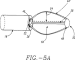
図5Aを参照すると、アーム44は、このバスケットアセンブリを拡張して括約筋壁26と噛み合わせるために、外向きに湾曲した形状記憶を有し得、湾曲(すなわち、反り54)の量は、バスケットアセンブリ50の長手軸28から0〜2インチの範囲から選択可能である。曲線形状のアーム44’の場合には、拡張アーム44’は、湾曲的かつ対称的に、間隔を置いて配置されている。
【0028】
図5Bで示した他の実施態様では、拡張可能部材55(これは、バルーンであり得る)は、バスケットアセンブリ50の内部または外部に連結されている。バルーン55はまた、連結され、気体または液体を用いて、管腔36によって拡張される。種々の他の実施態様(図示せず)では、アーム44は、非対称的に間隔を置いて配置され得るか、および/または360°未満の円弧で配置され得る。また、アーム44は、製造時にあらかじめ成形され得るか、または医師により成形され得る。
【0029】
今ここで、図6Aを参照すると、アーム44はまた、シャフト管腔36と連結され得る連続管腔58を備えて、中実または中空であり得る。これらの連結された管腔は、シャフト18からバスケットアセンブリ50上の任意の点への流体または電極送達部材60の送達用の経路を提供する。種々の実施態様では、電極送達部材60は、絶縁ワイヤ、絶縁ガイドワイヤ、内部ワイヤ付きプラスチック被覆ステンレス鋼ハイポチューブまたは内部ワイヤ付きプラスチックカテーテルであり得、これらの全ては、当業者に公知である。図6Bで示すように、アーム44はまた、部分的に開いたチャンネル62(これはまた、トラック62とも呼ばれる)を有し得、これは、電極送達部材60用のガイドトラックとして、機能する。図6Aに戻って参照すると、アーム44は、その長さに沿った任意の点にて、1つ以上の開口部64を有し得、これにより、括約筋壁26またはその中にて、エネルギー送達装置22を制御して配置できるようになる。今ここで、図7を参照すると、開口部64は、その長さの全部または一部において、テーパを付けた部分66または段を付けた部分68を有し得、これらは、括約筋壁26へのエネルギー送達装置22の貫入の深さを制御するのに使用される。図6Aに戻って参照すると、開口部64は、アーム管腔58およびシャフト管腔36と組み合わせて、本明細書中で記述するように、処置部位12への冷却液70または電解液72の送達に使用され得る。さらに、アーム44はまた、複数の長手方向に間隔を置いて配置した放射線不透過性またはエコー源性のマーカーまたはトレース(これは、図面では図示しておらず、適当な材料から形成されている)を運ぶことができて、蛍光透視または超音波検査を介して、バスケットアセンブリ50を見ることが可能となる。適当な放射線不透過性材料には、白金または金が挙げられるのに対して、適当なエコー源性材料には、米国特許第5,688,490号および第5,205,287号で記述されるように、気体充填微粒子が挙げられる。アーム44はまた、当業者に周知の視覚医療画像化方法および機器(例えば、内視鏡方法)を介したそれらの確認を容易にするために、カラーコード化され得る。
【0030】
本発明の他の実施態様では、支持部材74は、2本以上のアーム44に装着される。支持部材74(これはまた、支柱とも呼ばれる)は、図8で示すように、バスケットアセンブリ50の湾曲に沿って、アーム44に装着できる。開口部64は、1つ以上の場所で、放射状支持部材74を通って伸長できる。放射状支持部材74は、以下の機能を果たす:i)括約筋16の皺を開けて消去するのを容易にする;ii)開口部64と括約筋壁26との接触を高める;そしてiii)アーム44が束となる傾向を防止するかまたは少なくする。放射状支持部材74の断面幾何学的形状は、長方形または円形であり得るが、他の幾何学的形状は、同様に適当であることが分かる。
【0031】
図9で示した1実施態様では、アーム44は、バスケットキャップ52に装着され、これは、次に、シャフト18の上を自由に移動するが、シャフトキャップ78により、遠位で停止される。1本以上のプルワイヤ80は、バスケットキャップ52に装着され、また、括約筋処置器具10の近位フィッティング34にて、可動性フィッティング82に装着される。プルワイヤ80を可動性フィッティング82で引き戻したとき、バスケットアセンブリ50の反り54は、54’にまで上がり、バスケットアセンブリ50により括約筋壁26または隣接構造体に加えられる接触力および接触量が高まる。バスケットアセンブリ50はまた、たわみ機構80により、側面から側面へと反らすことができる。これにより、医師は、体内にて、このバスケットアセンブリを遠隔的に指し示して操縦可能になる。図10で示す1実施態様では、たわみ機構84は、第二プルワイヤ80’を備え、これは、シャフトキャップ78に装着されており、また、近位フィッティング34と一体化された可動性スライド86にも装着されている。
【0032】
今ここで、エネルギー送達の論述に目を向けると、本発明の1つ以上の実施態様で使用できる適当な電源24およびエネルギー送達装置22には、以下が挙げられる:(i)高周波(RF)電極に連結されたRF源;(ii)光ファイバーに連結されたコヒーレント光源;(iii)光ファイバーに連結された非コヒーレント光源;(iv)加熱流体であって、これは、加熱流体を受容するように構成された閉鎖チャネルを備えたカテーテルに連結ている;(v)加熱流体であって、これは、加熱流体を受容するように構成された開口チャネルを備えたカテーテルに連結されている;(vi)冷却流体であって、これは、冷却流体を受容するように構成された閉鎖チャネルを備えたカテーテルに連結されている;(vii)冷却流体であって、これは、冷却流体を受容するように構成された開口チャネルを備えたカテーテルに連結されている;(viii)極低温流体;(ix)抵抗加熱源;(x)マイクロ波源であって、これは、915MHz〜2.45GHzのエネルギーを与え、そしてマイクロ波アンテナに連結されている;(xi)超音波出力源であって、これは、超音波エミッタに連結されており、ここで、この超音波出力源は、300KHz〜3GHzの範囲のエネルギーを生じる;または(xii)マイクロ波源。本願の残りの部分の論述を簡単にするために、使用される電源はRF電源であり、そして、エネルギー送達装置22は1つ以上のRF電極88であり、これはまた、電極88とも記述される。しかしながら、本明細書中で言及した他の電源およびエネルギー送達装置の全ては、括約筋処置器具10に同等に適用できる。
【0033】
RFエネルギーの場合については、RF電極88は、接地パッド(ground pad)電極と共に、双極様式または単極様式のいずれかで操作され得る。単極RFエネルギー送達様式では、不関電極パッチ(これは、他の電気的接点を形成して電気回路を完成するために、身体に適用される)と組み合わせて、単一電極88が使用される。2個以上の電極88を使用するとき、双極操作が可能である。複数の電極88が使用され得る。これらの電極は、本明細書中で記述しているように、冷却され得る。電極88は、当業者に周知のハンダ付け方法を使用することにより、電極送達部材60に装着できる。適当なハンダには、Megatrode Corporation(Milwaukee,Wisconsin)により供給されているMegabond Solderが挙げられる。
【0034】
適切な電解液72には、生理食塩水、カルシウム塩溶液、カリウム塩溶液などが挙げられる。電解液72は、処置部位12での標的組織の導電率を高める。伝導性の高い流体(例えば、電解液72)を組織に注入するとき、注入した組織の電気抵抗は、低くなり、次に、注入した組織の導電率が高まる。結果として、電極88を取り囲む組織が乾燥する(組織の電気抵抗を高める本明細書中で記述した状態)傾向は殆どなく、この組織がRFエネルギーを運ぶ能力が非常に高くなる。図11を参照すると、濃縮電解液72を大量に注入した組織ゾーンは、強化電極88’として実際に作用する程に導電性になり得る。強化電極88’の効果は、処置部位12に伝導できる電流の量を多くして、一定時間にて、ずっと大きな容量の組織を加熱できるようにすることにある。
【0035】
また、このエネルギー源がRFのとき、電源24(これは、今ここで、RFエネルギー源24と呼ぶ)は、複数のチャネルを有し得、各電極88に変調出力を別々に送達する。このことは、優先的な加熱(これは、伝導性のより高いゾーンに、より多くのエネルギーが送達されるときに起こり、伝導性がより低い組織に配置された電極88の回りでは、少ない加熱しか起こらない)を減らす。もし、組織での組織水和レベルまたは血液注入速度が不均一なら、単一チャネルRFエネルギー源24は、大きさが比較的に揃った外傷14を発生させる出力を供給するために、使用され得る。
【0036】
電極88は、種々の形状および大きさを有し得る。可能な形状には、円形、長方形、円錐形およびピラミッド形(pyramoidal)が挙げられるが、これらに限定されない。電極表面は、滑らかかまたは織り目を付けられ、そして凹面または凸面であり得る。電極88の伝導性表面積は、0.1mm2〜100cm2の範囲であり得る。他の外形および表面積は、同等に適切であり得ることが分かる。1実施態様では、電極88は、食道壁の平滑筋、括約筋16または他の解剖学的構造を貫入するのに充分な鋭さおよび長さの針形状であり得る。図12および13で示したこの実施態様では、針電極90は、アーム44に装着されており、そして絶縁層92を有して、露出セグメント95以外の絶縁セグメント94を覆う。この開示の目的のために、絶縁体または絶縁層は、熱エネルギー流、RFエネルギー流または電気エネルギー流のいずれかに対する障壁である。絶縁セグメント94は、括約筋壁26へと伸長して絶縁セグメント94の近くまたは隣接した保護部位97へのRFエネルギー伝達を最小にするのに充分な長さである(図13を参照)。絶縁セグメント94に対する典型的な長さには、1〜4mmが挙げられるが、これらに限定されない。針電極90に適当な材料には、304ステンレス鋼、および当業者に公知の他のステンレス鋼が挙げられるが、これらに限定されない。絶縁層92に適当な材料には、ポリイミドおよびポリアミドが挙げられるが、これらに限定されない。
【0037】
括約筋処置器具10の導入中では、バスケットアセンブリ50は、収縮状態にある。一旦、括約筋処置器具10を処置部位12に正しく配置すると、針電極90は、バスケットアセンブリ50の拡張により展開されて、その結果、針電極90が括約筋壁26の平滑筋組織内へと突出する(図14を参照)。針貫入の深さは、0.5〜5mmの範囲で選択可能であり、そして0.1〜4mmの範囲で選択可能であり得る一定増分で、アーム44の反り54を変えるように可動性フィッティング82を位置合わせすることにより、達成される。針電極90は、絶縁ワイヤ60を介して、電源24に連結される。
【0038】
図15で示した括約筋処置器具10の他の実施態様では、針電極90は、バスケットアーム44にある開口部64から、食道壁の平滑筋または他の括約筋16へと前進される。この場合、針電極90は、電極送達部材60により、RF電源24に連結される。この実施態様では、針貫入の深さは、開口部64に位置している段を付けた部分66またはテーパを付けた部分68の手段によって、選択可能である。図16を参照すると、開口部64および針電極90は、針電極90を括約筋壁26へと挿入している時間中にて、括約筋壁26への針電極90の貫入角度96(これはまた、出現角度96(emergence angle)とも呼ばれる)が十分一定のままであるように、括約筋壁組織に対する裂けまたは不要な外傷が存在しないように、構成されている。これは、以下のパラメータおよび規準を選択することにより、促進される:i)開口部64の出現角度96(これは、1〜90°で変わることができる);ii)開口部64の曲線部分100の円弧半径98(これは、0.001〜2インチで変わることができる);iii)開口部内径102と針電極外径104との間のクリアランス量(これは、0.001”と0.1”との間で変わることができる);およびiv)電極送達部材60上の潤滑性被覆(例えば、テフロン(登録商標)または当業者に周知の他の被覆)の使用。また、この実施態様では、絶縁セグメント94は、電極90の外部に調節可能に配置し得るスリーブの形状であり得る。
【0039】
図17で示す他の代替的な実施態様では、針電極90を装着した電極送達装置60は、遠位シャフト末端32にて、管腔36から出て、括約筋壁26と接触して配置できる。このプロセスは、案内カテーテルとして当業者に公知の中空案内部材101(そこを通って、電極送達部材60が前進される)を使用することにより、容易にされ得る。案内カテーテル101はまた、括約筋壁26への針電極90の貫入深さを制御するために、その遠位端にて、段を付けた部分66またはテーパを付けた部分68を備え得る。
【0040】
組織を通って流れるRFエネルギーは、このRFエネルギーのこの組織への吸収のために、この組織の加熱を引き起こし、また、この組織の電気抵抗のために、オーム加熱を引き起こす。この加熱は、冒された細胞に対して傷害を起こし得、細胞死(細胞壊死としても知られている現象)を引き起こすのに実質的に充分であり得る。本願の残りの部分の論述を簡単にするために、細胞傷害には、電極88からのエネルギー送達から生じる全ての細胞の影響から、細胞壊死まで(それを含めて)が挙げられる。細胞傷害は、局所麻酔を使った比較的に簡単な医療手順として、達成できる。1実施態様において、細胞傷害は、括約筋16の粘膜層の表面または隣接解剖学的構造の表面から約1〜4mmの深さまで進行する。
【0041】
今ここで、図18A、18Bおよび18Cを参照すると、電極88および/または開口部64は、外傷14の所望の配置およびパターンを生じるために、拡張デバイス20またはバスケットアセンブリ50に沿って、種々のパターンで分布され得る。典型的な電極および開口部の分布パターンには、放射状分布105(図18Aを参照)または長手軸方向分布106(図18Bを参照)が挙げられるが、これらに限定されない。電極および開口部の配置のための他のパターンおよび幾何学的形状(例えば、螺旋状分布108(図18Cを参照))もまた、適切であり得ることが分かる。これらの電極は、以下で記述するように、冷却され得る。
【0042】
図19は、括約筋処置器具10を使用する手順の1実施態様を図示しているフローチャートである。この実施態様において、括約筋処置器具10は、まず、局所麻酔下にて、食道に導入される。括約筋処置器具10は、それ単独で、または内視鏡(示さず)(例えば、米国特許第5,448,990号および同第5,275,608号(その内容は、本明細書中で参考として援用されている)で開示されたもの)の管腔を通って、または当業者に公知の類似の食道アクセスデバイスを通って、食道に導入できる。バスケットアセンブリ50は、本明細書中で記述しているように、拡張される。これは、LESの皺の一部または全部を充分に消すために、LESを一時的に拡張するのに役立つ。代替実施態様では、食道拡張および引き続くLES皺消去は、シャフト管腔36または内視鏡または上記の類似の食道アクセスデバイスを通って食道に導入された気体を用いて、食道のガス注入(公知技術)により、達成できる。一旦、処置が完結すると、バスケットアセンブリ50は、その前展開(すなわち、収縮)状態へと戻り、そして括約筋処置器具10は、食道から引き出される。この結果、LESは、大体、その処置前の状態および直径に戻る。上記手順は、全部または一部で、体内の他の括約筋の処置に適用できることが分かる。
【0043】
この手順の診断段階は、種々の診断法を用いて達成され得、この診断法には、以下が挙げられるが、これらに限定されない:(i)食道に挿入された内視鏡または他の視覚装置による食道の内面の視覚化;(ii)処置すべき組織用のベースラインを確立するために超音波検査を使用する食道壁の内部形態の視覚化;(iii)食道粘膜層と括約筋処置器具10との間の導電率を決定するためのインピーダンス測定;および(iv)種々の時間(これは、LES平滑筋組織の脱分極、収縮および再分極のような事象を含み得る)におけるLESの電位の測定および表面マッピング。この後者の技術は、LESまたは隣接解剖学的構造での標的処置部位12(これらは、LESの平滑筋の異常または不適切な分極および弛緩のための焦点107または経路109として、作用している)を決定するために行われる(図20を参照)。
【0044】
この手順の処置段階では、処置部位12へのエネルギーの送達は、フィードバック制御下にて、手動で、または両方を組み合わせて、行うことができる。フィードバック制御(本明細書中で記述している)により、括約筋処置器具10は、医師の世話を最小限にして、処置中にて、食道に配置し保持できるようになる。電極88は、全標的処置部位12またはその一部のみを処置するために、多重化できる。フィードバックを含めることができ、これは、以下の方法の1つ以上の使用により達成される:(i)視覚化;(ii)インピーダンス測定;(iii)超音波検査;(iv)温度測定;および(v)検圧による括約筋収縮力測定。このフィードバック機構により、所望のパターンで、異なる電極88の選択したオンオフ切換が可能となり、これは、1つの電極88から隣接した電極88へと連続的であり得、または非隣接電極88間で活動し得る。個々の電極88は、多重化され、そして制御装置により、容積制御される。
【0045】
LESまたは括約筋16での細胞傷害の面積および規模は、変えることができる。しかしながら、55〜95℃の範囲の組織温度を達成してLESまたは括約筋壁26の内面から1〜4mmの範囲の深さで外傷14を生じることができるように、標的処置部位12に充分なエネルギーを送達することが望ましい。食道壁に送達される典型的なエネルギーは、限定されないが、1つの電極88当り、100ジュールと50,000ジュールとの間の範囲を含む。また、得られる外傷14が、線維芽細胞110、筋繊維芽細胞112、マクロファージ114および組織治癒プロセスが関与する他の細胞により、外傷14の浸潤を引き起こすのに充分な規模および面積の細胞傷害を有するように、充分なエネルギーを送達するのが望ましい(図21を参照)。図22で示すように、これらの細胞は、外傷14の周りの組織の収縮を引き起こして、その容量を減らすか、または外傷14での生体力学的特性を変えて、その結果、LESまたは括約筋16を締める。これらの変化は、図19Bで示した変形外傷14’で反映されている。外傷14の直径は、0.1〜4mmの間で変えることができる。外傷14は、粘膜層に対する熱的損傷のリスクを少なくするために、4mm未満の直径であるのが好ましい。1実施態様では、平滑筋の壁の中心にある2mm直径の外傷14は、1mmの緩衝ゾーンを与えて、粘膜、粘膜下組織および外膜に対する損傷を防止するが、依然として、平滑筋の壁厚のおよそ50%で、細胞浸潤および引き続いた括約筋の締めを可能にする(図23を参照)。
【0046】
診断上の見地から、作成した外傷14の大きさおよび位置を含めて、LESの内面および壁または他の括約筋16を画像化するのが望ましい。制御装置に入力できて処置部位へのエネルギーの送達を指示するのに使用できるこれらの構造のマップを作成するのが望ましい。図24を参照すると、これは、超音波検査(公知手順)の使用により達成でき、これは、拡張デバイス20またはバスケットアセンブリ50の上に配置された1つ以上の超音波変換器118と連結された超音波電源116の使用を包含する。出力は、超音波電源116に関連している。
【0047】
各超音波変換器118は、裏打ち材料(backing)122(これは、次に、拡張デバイス20またはバスケットアセンブリ50に装着される)上に取り付けられた圧電性結晶120を備えることができる。超音波レンズ124は、電気絶縁材料126上で製作されているが、圧電性結晶120の上に取り付けられている。圧電性結晶120は、電気導線128により、超音波電源116に接続されている。各超音波変換器118は、超音波エネルギーを、隣接組織に伝達する。超音波変換器118は、画像化プローブ(例えば、Hewlett Packard Company(Palo Alto,California)により製造され販売されているModel 21362)の形態であり得る。1実施態様では、2個の超音波変換器118は、拡張デバイス20またはバスケットアセンブリ50の反対側に配置されて、選択した括約筋16にある外傷14の大きさおよび位置を描写する画像を作成する。
【0048】
外傷14は、主に、括約筋壁26の内面から1〜4mmの範囲の深さで、選択した括約筋16の平滑筋層に位置していることが望ましい。しかしながら、外傷14は、括約筋壁26内にて、数および位置の両方を変えることができる。LESまたは他の括約筋16の選択した締め具合を得るために、括約筋平滑筋組織内にて、複数の外傷14のパターンを生じるのが望まれ得る。図25A〜Dで示した典型的な外傷パターンには、以下が挙げられるが、これらに限定されない:(i)同心円の外傷14であって、これらは、全て、平滑筋層にて、一定深さで、括約筋16の半径方向軸に沿って、一様に間隔を開けて配置されている;(ii)波状または折り畳んだ円の外傷14であって、これらは、平滑筋層にて、異なる深さで、括約筋16の半径方向軸に沿って、一様に間隔を開けて配置されている;(iii)平滑筋にて、異なる深さでランダムに分布された外傷14であって、これらは、半径方向にて、一様に間隔を開けて配置されている;および(iv)平滑筋壁にて、1つまたはそれ以上の半径方向位置にある偏心パターンの外傷14。従って、RFおよび熱エネルギー貫入括約筋16の深さは、制御され、そして選択可能であり得る。括約筋16へのエネルギーの選択的な適用は、標的処置部位全体12、その一部へのRFエネルギーの一様な貫入であり得るか、または括約筋16の状態に依存して、異なる量のRFエネルギーの異なる部位への適用であり得る。望ましいなら、その細胞傷害の面積は、各処置の場合に対して、実質的に同じであり得る。
【0049】
図26を参照すると、細胞傷害の程度および面積を少なくするために、エネルギーの送達前、送達中および送達後にて、電極−組織界面130の近くの領域の全部または一部を冷却することが望まれ得る。具体的には、冷却を使用することは、括約筋壁26の粘膜層を保存し、そして外傷14の近傍にて、冷却したゾーン132に対する細胞損傷の程度を保護するか、そうでなければ、低下させる。今ここで、図27を参照すると、これは、開口部64(これは、シャフト管腔36に流体連絡しており、すなわち、次に、流体リザーバ134および制御ユニット136(その操作は、本明細書中で記述されており、その流体の送達を制御する)と流体連絡している)により送達される冷却液70を使用することにより、達成できる。
【0050】
同様に、電極88の全部または一部を冷却することもまた、望まれ得る。電極88を通る熱の急速な送達は、(組織および流体(例えば、血液)との接触により)電極88上での焦げた生体物質の蓄積を生じ得、これは、電極88から隣接組織への熱エネルギーおよび電気エネルギーの両方の流れを妨害し、そしてRF電源24で設定されたカットオフ値を超える電気インピーダンスの上昇を引き起こす。類似の状況は、電極88に隣接した組織の乾燥から生じ得る。電源88の冷却は、先に記述したような開口部64により送達される冷却液70により、達成できる。今ここで、図28を参照すると、電極88はまた、電極88にある流体チャネル138を経由して冷却され得、この流体チャネルは、流体リザーバ134および制御ユニット136に流体連絡している。
【0051】
図29で示すように、処置部位12にある括約筋組織の温度を感知するために、電極88に隣接し、またはその上で、1つまたはそれ以上のセンサ140が配置され得る。さらに具体的には、センサ140により、電極−組織界面130での括約筋壁26の表面温度の正確な決定が可能になる。この情報は、括約筋壁26の内面へのエネルギーおよび冷却液70の両方の送達を制御するために使用できる。種々の実施態様では、センサ140は、拡張デバイス20またはバスケットアセンブリ50上の任意の位置に配置できる。センサ140に使用され得る適切なセンサは、熱電対、光ファイバー、抵抗性ワイヤ、熱電対IR検出器などを含む。適切なセンサ140用の熱電対には、銅コンスタンテン(constantene)を備えたT型、J型、E型およびK型(これらは、当業者に周知である)が挙げられる。
【0052】
センサ140からの温度データは、制御ユニット136のマイクロプロセッサメモリー内に保存されたアルゴリズムによって、制御ユニット136にフィードバックされる。これらの流体ラインを通って、適切な流速および持続時間で流体を送達して、電極−組織界面130での制御温度を提供するために、電気的に制御したマイクロポンプ(図示せず)には、指示が送られる(図27を参照)。
【0053】
制御ユニット136のリザーバは、この流体を冷却するかまたは加熱するかいずれかにより、冷却液70の温度を制御する性能を有し得る。あるいは、充分な大きさの流体リザーバ134が使用され得、ここで、冷却液70は、正常な体温またはそれに近い温度で、導入される。熱的に絶縁したリザーバ142を使用して、冷却液70の冷却または加熱の必要なしに、この組織温度の充分な制御が達成され得る。冷却液70の流れは、電気−組織界面130での温度制御を与えるために、制御ユニット136または他のフィードバック制御システム(本明細書中で記述した)により、制御される。
【0054】
第二の診断段階は、この処置が完結した後、包含され得る。これは、LES締め処置の成功、および現在または後の段階にて食道の全部または一部だけに対して第二段階の処置を行うべきかどうかの指標を与える。この第二診断段階は、以下の方法の1つまたはそれ以上により、達成される:(i)視覚化;(ii)インピーダンスを測定すること;(iii)超音波検査;(iv)温度測定;または(v)マノメトリーによるLES張力および収縮力の測定。
【0055】
1実施態様では、括約筋処置器具10は、開いたまたは閉じたループフィードバックシステムに連結される。ここで、図30を参照すると、開いたまたは閉じたループフィードバックシステムは、センサ346をエネルギー源392に連結する。この実施態様では、電極314は、1つまたはそれ以上のRF電極314である。
【0056】
この組織またはRF電極314の温度がモニターされ、それに従って、エネルギー源392の出力が調節される。医師は、もし望むなら、この閉じたまたは開いたループシステムを無効にできる。この閉鎖または開放ループシステムには、出力をオンおよびオフに切り換えるためだけでなく、この出力を調節するために、マイクロプロセッサ394が備えられ組み込まれる。この閉じたループシステムは、制御装置として供するため、この温度をモニターするため、このRF出力を調整するため、その結果を分析するため、この結果を再給送するため、次いで、この出力を調節するために、マイクロプロセッサ394を利用する。
【0057】
センサ346およびこのフィードバック制御システムの使用と共に、RF電極314に隣接した組織は、本明細書中で述べているように、電極314または隣接組織にて過度の電気インピーダンスが発生するために、この電力回路の電極314への中断を引き起こすことなく、選択した期間にわたって、所望温度で維持できる。各RF電極314は、独立した出力を発生するリソース(resources)に接続される。この出力は、選択した時間にわたって、RF電極314で、選択したエネルギーを維持する。
【0058】
RF電極314を通って送達される電流は、電流センサ396により測定される。電圧は、電圧センサ398により、測定される。次いで、出力およびインピーダンス計算装置400にて、インピーダンスおよび出力が計算される。これらの値は、次いで、ユーザーインターフェイスおよびディスプレイ402で表示される。出力およびインピーダンス値を表わす信号は、制御装置404により、受容される。
【0059】
制御信号は、制御装置404により発生されるが、これは、実際の測定値と所望値との間の差に比例している。この制御信号は、各個のRF電極314で送達される所望出力を維持するために、この出力を適切な量で調節するのに電力回路406により使用される。
【0060】
類似の様式で、センサ346で検出された温度は、選択した出力を維持するためのフィードバックを与える。センサ346での温度は、最大プリセット温度を超えたとき、エネルギーの送達を遮断するための安全手段として、使用される。それらの実際の温度は、温度測定装置408で測定され、これらの温度は、ユーザーインターフェイスおよびディスプレイ402で表示される。制御信号は、制御装置404により発生するが、実際に測定した温度と所望温度との間の差に比例している。この制御信号は、センサ346で送達される所望温度を維持するために、この出力を適切な量で調節するのに電源回路406により使用される。センサ346において、電流、電圧および温度を測定するために、マルチプレクサを備えることができ、エネルギーは、単極様式または双極様式で、RF電源314に送達できる。
【0061】
制御装置404は、デジタルまたはアナログ制御装置、またはソフトウエア付きコンピューターであり得る。制御装置404がコンピューターであるとき、それは、システムバスによって連結されたCPUを備えることができる。このシステムは、当該技術分野で公知であるように、キーボード、ディスクドライブ、または他の不揮発性メモリーシステム、ディスプレイ、および他の周辺機器であり得る。また、このバスには、プログラムメモリーおよびデータメモリーが連結される。
【0062】
ユーザーインターフェイスおよびディスプレイ402は、操作者制御機器およびディスプレイを備える。制御装置404は、画像化システムに連結でき、これには、超音波、CTスキャナ、X線撮影、MRI、乳房X線撮影などが挙げられるが、これらに限定されない。さらに、直接視覚化および触覚画像化が使用できる。
【0063】
電流センサ396および電圧センサ398の出力は、RF電極314での選択した出力レベルを維持するために、制御装置404により使用される。送達されるRFエネルギーの量は、この出力量を制御する。電極314に送達される出力のプロフィールは、制御装置404に備えることができ、送達すべきエネルギーのプリセット量もまた、プロフィールされ得る。
【0064】
制御装置404への回路網、ソフトウエアおよびフィードバックにより、プロセス制御、および選択した出力設定(これは、電圧または電流の変化とは無関係である)の維持が得られ、これは、以下を変えるのに、使用される:(i)選択した出力設定、(ii)デューティサイクル(オン−オフ時間)、(iii)双極または単極エネルギー送達、および(iv)流体送達(これには、流量および圧力が含まれる)。これらのプロセス変数は、センサ346でモニターされる温度に基づいて、電圧または電流の変化に無関係な出力の所望の送達を維持しつつ、制御され変えられる。
【0065】
今ここで、図31を参照すると、電流センサ396および電圧センサ398は、アナログ増幅器410の入力に接続される。アナログ増幅器410は、センサ346と共に使用するための従来の差動増幅器であり得る。アナログ増幅器410の出力は、アナログマルチプレクサ412により、A/D変換器414の出力に連続的に接続されている。アナログ増幅器410の出力は、各個の感知温度を表わす電圧である。デジタル化増幅器出力電圧は、A/D変換器414により、マイクロプロセッサ394に供給される。マイクロプロセッサ394は、Motorolaから入手できる68HCII型であり得る。しかしながら、インピーダンスまたは温度を計算するためには、任意の適切なマイクロプロセッサまたは汎用性デジタルまたはアナログコンピューターが使用できることが分かる。
【0066】
マイクロプロセッサ394は、インピーダンスおよび温度のデジタル画像を連続的に受容し保存する。マイクロプロセッサ394により受容される各デジタル値は、異なる温度およびインピーダンスに対応する。
【0067】
計算された出力およびインピーダンス値は、ユーザーインターフェイスおよびディスプレイ402で指示できる。出力またはインピーダンスの数値表示の代わりに、またはそれに加えて、計算されたインピーダンスおよび出力値は、マイクロプロセッサ394により、出力およびインピーダンス限界と比較できる。これらの値が所定の出力またはインピーダンス値を超えるとき、ユーザーインターフェイスおよびディスプレイ402において、警告を与えることができ、さらに、RFエネルギーの送達は、減少されるか、変更されるか、または遮断できる。マイクロプロセッサ394からの制御信号は、エネルギー源392により供給される出力レベルを変えることができる。
【0068】
図32は、温度およびインピーダンスフィードバックシステムのブロック線図を図示しており、これは、組織部位416へのエネルギーの送達をエネルギー源392により制御するため、および電極314および/または組織部位416への冷却液70の送達を流量調節器418により制御するために、使用できる。エネルギーは、エネルギー源392により、RF電極314に送達され、そして組織部位416に適用される。モニター420は、組織に送達されたエネルギーに基づいて、組織インピーダンスを確認し、そして測定した組織インピーダンスと設定値とを比較する。もし、測定したインピーダンスが設定値を超えるなら、エネルギー源392には、無効化信号422が伝達されて、RF電極314へのそれ以上のエネルギーの伝達を止める。もし、測定したインピーダンスが、許容できる限界内にあるなら、この組織には、引き続いて、エネルギーが加えられる。
【0069】
電極314および/または組織部位416への冷却液70の制御は、以下の様式で行われる。エネルギーの適用中にて、温度測定装置408は、組織部位416および/またはRF電極314の温度を測定する。比較器424は、測定した温度を表示する信号を受容し、そしてこの値を、所望温度を表示するプリセット信号と比較する。もし、この組織温度が高すぎるなら、比較器424は、流量調節器418(これは、電気的に制御したマイクロポンプ(図示せず)に接続されている)に信号を送り、高い冷却液流速の必要性を表示し、またはもし、この温度が所望温度を超えていないなら、比較器424は、この流速を現存のレベルに維持するように、流量調整器418に信号を送る。
【0070】
本発明の好ましい実施態様の前述の記述は、説明および記述の目的のために、提示された。それは、全てを網羅することを意図しておらず、または開示した正確な形状に本発明を限定することを意図していない。明らかに、当業者には、多くの変更および変形が明白である。本発明の範囲は、上記特許請求の範囲およびそれらの等価物により規定されることを意図している。
【図面の簡単な説明】
【図1】 図1は、上部GI路(これは、食道および下部食道括約筋を含む)および下部食道括約筋への本発明の括約筋処置器具の配置の図解側面図である。
【図2】 図2は、拡張状態および収縮状態でのエネルギー送達装置、電源および拡張デバイスを図示している本発明の側面図である。
【図3】 図3は、近位フィッティング、接続部および近位および遠位シャフト部分を備える可撓性シャフト上の部品を図示している本発明の側面図である。
【図4】 図4は、本発明の実施態様で使用されるバスケットアセンブリの側面図を図示している。
【図5A】 図5Aは、バスケットアセンブリの側面図であり、これは、このバスケットアセンブリの反りの範囲を図示している。
【図5B】 図5Bは、バスケットアセンブリに連結されたバルーンを図示している斜視図である。
【図6A】 図6Aは、バスケットアームとシャフトとの接合部の側面図であり、これは、その可動性ワイヤの前進または流体の送達に使用される経路を図示している。
【図6B】 図6Bは、本発明の代替実施態様でのバスケットアームの正面図であり、これは、この可動性ワイヤを前進するのに使用されるアームにあるトラックを図示している。
【図7】 図7は、バスケットアームの一部分の断面図であり、これは、バスケットアーム開口部にある段を付けた部分およびテーパを付けた部分を図示している。
【図8】 図8は、バスケットアセンブリの側面図であり、これは、その放射状支持部材の配置を図示している。
【図9A】 図9Aは、括約筋処置器具の側面図であり、これは、そのバスケットアセンブリの反りを高めるために、本発明の1実施態様で使用される機構を図示している。
【図9B】 図9Bは、図9Aと類似した図であり、これは、反り状態を高めたバスケットアセンブリを示している。
【図10】 図10は、括約筋処置器具の側面図であり、これは、そのたわみ機構を図示している。
【図11】 図11は、強化RF電極を作成するための電解液の使用を図示している側面図である。
【図12】 図12は、針電極の使用を図示しているバスケットアセンブリの側面図である。
【図13】 図13は、RFエネルギーから組織領域を保護するため、針電極上での絶縁セグメントの使用を図示している側面図である。
【図14】 図14は、バスケットアセンブリの拡張による針電極の括約筋壁への配置を図示している側面図である。
【図15】 図15は、バスケットアームにある開口部から電極送達部材を前進することによる括約筋壁への針電極の配置を図示している側面図である。
【図16】 図16は、針電極の括約筋壁への貫入角度を選択し維持するのに使用されるバスケットアーム開口部の構成を図示している断面図である。
【図17】 図17は、シャフトの遠位端から電極送達部材を直接前進させることによる括約筋壁への針電極の配置を図示している側面図である。
【図18A】 図18Aは、本発明の拡張デバイス上の電極の放射状分布を図示している側面図である。
【図18B】 図18Bは、本発明の拡張デバイス上の電極の長手軸方向分布を図示している側面図である。
【図18C】 図18Cは、本発明の拡張デバイス上の電極の螺旋状分布を図示している側面図である。
【図19】 図19は、本発明の器具を使用する括約筋処置方法を図示しているフローチャートである。
【図20】 図20は、括約筋平滑筋組織の側面図であり、これは、下部食道括約筋または他の組織の平滑筋における異常電気信号の発生および伝導のための電磁焦点および経路を図示している。
【図21】 図21は、括約筋壁の側面図であり、これは、本発明の括約筋処置器具を用いた処置に続いて、括約筋の平滑組織での外傷への組織治癒細胞の浸潤を図示している。
【図22】 図22は、図21と類似した図であり、これは、細胞浸潤により引き起こされる外傷部位の収縮を図示している。
【図23】 図23は、食道壁の側面図であり、これは、食道括約筋の平滑筋層での外傷の好ましい配置を図示している。
【図24】 図24は、本発明の1実施態様の超音波変換器、超音波レンズおよび電源を図示している側面図である。
【図25A】 図25Aは、括約筋壁の側面図であり、これらは、本発明の器具により作成される外傷の種々のパターンを図示している。
【図25B】 図25Bは、括約筋壁の側面図であり、これらは、本発明の器具により作成される外傷の種々のパターンを図示している。
【図25C】 図25Cは、括約筋壁の側面図であり、これらは、本発明の器具により作成される外傷の種々のパターンを図示している。
【図25D】 図25Dは、括約筋壁の側面図であり、これらは、本発明の器具により作成される外傷の種々のパターンを図示している。
【図26】 図26は、括約筋壁の側面図であり、これは、その電極−組織界面への冷却液の送達および冷却ゾーンの形成を図示している。
【図27】 図27は、電極−組織界面へと流体を送達するのに使用される流路、流体接続部および制御ユニットを描写している。
【図28】 図28は、RF電極へと流体を送達するのに使用される流路、流体接続部および制御ユニットを描写している。
【図29】 図29は、拡張デバイスまたはバスケットアセンブリ上でのセンサの配置を図示している拡大側面図である。
【図30】 図30は、括約筋処置器具と共に使用できるフィードバック制御システムのブロック線図を描写している。
【図31】 図31は、図30のフィードバック制御システムと共に使用されるアナログ増幅器、アナログマルチプレクサおよびマイクロプロセッサのブロック線図を描写している。
【図32】 図32は、図30で描写されたフィードバック制御システムで実行される操作のブロック線図を描写している。[0001]
(Background of the Invention)
(Interrelated applications)
This application is a continuation-in-part of US patent application Ser. No. 08 / 731,372 filed on Oct. 11, 1996, which is filed on Oct. 6, 1994. No. 319,373, which is a continuation-in-part of U.S. patent application Ser. No. 08 / 286,862, filed Aug. 4, 1994. This is a continuation-in-part of U.S. patent application Ser. No. 08 / 272,162, filed on Jul. 7, 1994, which is incorporated by reference. And is a continuation-in-part application and is filed at the same time as an application entitled “GERD Treatment Apparatus and Method” (confirmed as attorney case number 14800-748) All applications are related to inventor Stuart D. Made in the name of Edwards, the contents of all of which are hereby incorporated by reference.
[0002]
(Field of Invention)
The present invention relates generally to sphincter treatment instruments and, more particularly, to instruments for treating esophageal sphincters.
[0003]
(Description of related technology)
Gastroesophageal reflux disease (GERD) is a common gastroesophageal disorder in which the contents of the stomach are expelled to the lower esophagus due to dysfunction of the lower esophageal sphincter (LES). These contents are very acidic and can be damaging to the esophagus, resulting in a number of possible complications of varying medical severity. The incidence of GERD reported in the United States is on the order of 10% of the population (Castell DO; Johnston BT: Gastroesophageal Reflex Disease: Current Strategies For Patient Management. 1 (2): 19 (4). April)).
[0004]
Acute symptoms of GERD include heartburn, lung injury and chest pain. In chronic conditions, GERD can cause the esophagus to undergo ulceration or esophagitis and cause more serious complications (including esophageal obstruction, significant blood loss and esophageal perforation). Severe esophageal ulceration occurs in 20-30% of patients over 65 years of age. In addition, GERD causes adenocarcinoma, or esophageal cancer, which has a rapid increase in incidence than any other cancer (Reynolds JC: Inflation Of Pathology, Severity, And Cost On The Medical Management). Of Gastroesophageal Reflux Disease. Am J Health System Pharm, 53 (22 Suppl 3): S5-12 (November 15, 1996)).
[0005]
One potential cause of GERD may be an abnormal electrical signal in the stomach LES or cardia. Such signals can cause more frequent relaxation of LES than normal, gastric contents that are acidic can be repeatedly excreted into the esophagus, and can cause the above complications. Studies have shown that abnormal electrical signals in the stomach and intestine can cause reflux events in these organs (Kelly KA et al .: Dual-gastric Reflex and Slowed Gastric Emptying by Electric Pain of the Cane. Duodenal Paceetter Potential. Gastroenterology. 1977 Mar; 72 (3): 429-433). In particular, medical studies have shown that sites of abnormal electrical activity or electrical focus (foci) can carry these signals (Karlstrom LH et al .: Electronic Journal Makers and Enterprise Reflex after Roux Gastroelectricity. 1989 September; 106 (3): 486-495). Mapping and ablation devices as described in US Pat. No. 5,509,419 can identify similar abnormal electrical sites in the heart that cause myocardial contractions to exhibit life-threatening patterns or rhythm abnormalities Has been treated. However, there are no devices or associated medical procedures currently available for electrical mapping and treatment of abnormal electrical sites in the LES and stomach as a means of treating GERD.
[0006]
Current drug therapies for GERD include histamine receptor blockers that reduce gastric acid secretion and other drugs that can completely block gastric acid. However, while pharmacological agents can provide short-term relief, they do not address the root cause of LES dysfunction.
[0007]
Surgical correction of GERD includes invasive procedures that require percutaneous introduction of the device into the abdomen. One such procedure, Nissen fundoplasty, involves building a new “valve” that supports the LES by wrapping the fundus around the lower esophagus. This procedure is a successful abdominal incision procedure with the usual risks of abdominal surgery, including postoperative infection, herniation at the surgical site, internal bleeding and esophageal or cardia perforation. In fact, in the last decade, a study of 344 patients reported that the morbidity of this procedure was 17% and the mortality rate was 1% (Urschel, JD: Complications of Antireflux Surgery, Am J Surg 166 (1): 68-70; (July 1993)). This complication rate raises both medical costs and the recovery phase of this procedure, and cannot be applied to certain patient populations (eg, elderly and non-immunized people).
[0008]
In an effort to perform Nissen fundoplasty with less invasive techniques, laparoscopic Nissen fundoplasty was developed. Laparoscopic Nissen fundoplasty is described by Dallemagne et al. (Surgical Laparoscopy and Endoscopy, Vol. 1, No. 3, (1991), pages 138-43) and Hindler et al. (Surgical Laparoscopy and Endoscope. Endocopy. 3, (1992), pages 265-272), except that the surgical operation is performed by a plurality of surgical cannulas introduced using trocars inserted in various parts of the abdomen. , Including virtually the same steps as Nissen fundoplication.
[0009]
Another attempt to perform fundoplasty with less invasive techniques is reported in US Pat. No. 5,088,979. In this procedure, an invagination device with a plurality of needles is inserted orally into the esophagus with the needles in a retracted position. These needles are stretched to engage the esophagus and wrap the tied esophagus beyond the gastroesophageal junction. A remotely operated stapling device (which is introduced percutaneously through an operating channel in the stomach wall) is actuated to surround the invaginated gastroesophageal junction and the involved gastric wall surrounding it Keep on.
[0010]
Yet another attempt to perform fundoplasty with less invasive techniques is reported in US Pat. No. 5,676,674. In this procedure, the jaw-like device is invaginated and the invaginated gastroesophageal joint is fastened to the fundus by an oral method using a remotely operated fastening device and the abdomen. The need for an incision is eliminated. However, this procedure still traumas the LES, and there is a postoperative risk of gastroesophageal leakage, infection and foreign body reaction, and the other two sequelae are foreign bodies (eg, surgical staples) implanted in the body Sometimes happens.
[0011]
Although the methods reported above are less invasive than open nissen fundoplasty, some of them still involve making an incision in the abdomen and hence the high morbidity associated with abdominal surgery. Including the risk of death and the risk of death and recovery. Others pose high infection risks associated with placing foreign bodies in the body. All procedures involve trauma to LES and include the risk of leaks at newly created gastroesophageal junctions.
[0012]
In addition to LES, there are other sphincters in the body that can cause disease states if they do not function properly or otherwise adversely affect the patient's lifestyle. Decreased muscle tone, or otherwise abnormal relaxation of the sphincter muscles, can result in loose tightening disease states (including but not limited to urinary incontinence).
[0013]
There is a need to provide instruments that treat the sphincter and reduce the frequency of sphincter relaxation. In addition, there is a need for a device that produces controlled cell necrosis in the sphincter tissue underlying the sphincter mucosa layer. In addition, there is a need for a device that forms cell necrosis at the sphincter and minimizes injury to the mucosal layer of the sphincter. Another need exists for an instrument that can controllably cause trauma to the sphincter without causing a permanent impairment in the ability of the sphincter to achieve a physiologically normal occlusion. Furthermore, there is a need for an instrument that causes tightening of the sphincter without permanently impairing the anatomical structure near the sphincter. In addition, there is a need for a device that causes cell necrosis in the lower esophageal sphincter to reduce the frequency of gastric reflux into the esophagus.
[0014]
(Summary of the Invention)
Accordingly, it is an object of the present invention to provide an instrument that treats the sphincter to reduce the frequency of sphincter relaxation.
[0015]
It is another object of the present invention to provide a device that causes controlled cell necrosis in the sphincter tissue underlying the sphincter mucosa layer.
[0016]
Yet another object of the present invention is to provide a device that causes cell necrosis in the sphincter to minimize damage to the mucosal layer of the sphincter.
[0017]
Yet another object of the present invention is to provide an instrument that can controllably cause trauma to the sphincter without causing a permanent impairment of the sphincter's ability to achieve a physiologically normal occlusion.
[0018]
Yet another object of the present invention is to provide an instrument that causes tightening of the sphincter without permanently damaging the anatomy close to the sphincter.
[0019]
Another object of the present invention is to provide a device that causes cell necrosis in the lower esophageal sphincter to reduce the frequency of gastric reflux into the esophagus.
[0020]
Yet another object of the present invention is to provide a device that reduces the frequency and severity of gastroesophageal reflux phenomenon.
[0021]
These and other objects of the present invention are provided in a sphincter treatment instrument. These instruments include an energy delivery device introduction member that includes a plurality of arms. Each arm has a distal end and a proximal end. The distal ends of these arms are connected as the proximal ends of these arms are connected. The energy delivery device introduction member is configured to be introduced into the sphincter muscle in an undeployed state and to expand into the deployed state to at least partially expand the sphincter muscle. A plurality of energy delivery devices are connected to the energy delivery device introduction member. At least some of the plurality of energy delivery devices can be controllably introduced from the energy delivery device introduction member into the sphincter.
[0022]
In other embodiments, the sphincter treatment instrument has an expandable basket structure. The expandable basket structure includes a first arm with a distal portion and a proximal portion, a second arm with a distal portion and a proximal portion, and a third arm with a distal portion and a proximal portion. Prepare. The proximal portions of the first, second and third arms are connected to each other. The distal portions of the first, second and third arms are connected to each other. The expanded basket structure has a non-deployed state and a deployed state, where the first, second and third arms are expanded away from each other. A first energy delivery device is coupled to the first arm and includes a distal portion that can be controllably advanced from the first arm to the sphincter.
[0023]
(Detailed explanation)
Referring now to FIGS. 1 and 2, one of the sphincter treatment instruments 10 used to deliver energy to the
[0024]
Referring to FIG. 2, the
[0025]
Referring now to FIG. 3, the flexible
[0026]
Referring now to FIG. 4, in one embodiment of the present invention, the
[0027]
Referring to FIG. 5A, the
[0028]
In another embodiment shown in FIG. 5B, the expandable member 55 (which can be a balloon) is coupled to the interior or exterior of the
[0029]
Referring now to FIG. 6A, the
[0030]
In other embodiments of the present invention, the
[0031]
In one embodiment shown in FIG. 9, the
[0032]
Turning now to the discussion of energy delivery,
[0033]
For the case of RF energy, the
[0034]
Suitable electrolyte solutions 72 include saline, calcium salt solutions, potassium salt solutions, and the like. The electrolytic solution 72 increases the conductivity of the target tissue at the
[0035]
Also, when the energy source is RF, the power source 24 (which will now be referred to herein as the RF energy source 24) may have multiple channels and deliver a modulated output to each
[0036]
The
[0037]
During the introduction of the sphincter treatment instrument 10, the
[0038]
In another embodiment of the sphincter treatment instrument 10 shown in FIG. 15, the
[0039]
In another alternative embodiment shown in FIG. 17, an
[0040]
The RF energy flowing through the tissue causes heating of the tissue due to absorption of this RF energy into the tissue and also causes ohmic heating due to the electrical resistance of the tissue. This heating can cause damage to the affected cells and can be substantially sufficient to cause cell death (a phenomenon also known as cell necrosis). To simplify the discussion of the remainder of this application, cell injury includes from the effects of all cells resulting from energy delivery from
[0041]
Referring now to FIGS. 18A, 18B and 18C, the
[0042]
FIG. 19 is a flowchart illustrating one embodiment of a procedure for using the sphincter treatment instrument 10. In this embodiment, the sphincter treatment instrument 10 is first introduced into the esophagus under local anesthesia. The sphincter treatment instrument 10 can be used alone or with an endoscope (not shown) (eg, US Pat. Nos. 5,448,990 and 5,275,608, the contents of which are incorporated herein by reference). ), Or similar esophageal access devices known to those skilled in the art. The
[0043]
The diagnostic phase of this procedure may be accomplished using a variety of diagnostic methods, including but not limited to: (i) an endoscope or other vision inserted into the esophagus Visualization of the inner surface of the esophagus with the device; (ii) Visualization of the internal form of the esophagus wall using ultrasonography to establish a baseline for the tissue to be treated; (iii) Esophageal mucosal layer and sphincter treatment instrument Impedance measurements to determine conductivity between 10; and (iv) the potential of LES at various times, which may include events such as LES smooth muscle tissue depolarization, contraction and repolarization Measurement and surface mapping. This latter technique acts as a
[0044]
During the treatment phase of this procedure, delivery of energy to the
[0045]
The area and magnitude of cytotoxicity at the LES or
[0046]
From a diagnostic standpoint, it is desirable to image the inner surface and walls or
[0047]
Each
[0048]
The
[0049]
Referring to FIG. 26, it is desirable to cool all or part of the region near the electrode-
[0050]
Similarly, it may also be desirable to cool all or part of
[0051]
As shown in FIG. 29, one or
[0052]
Temperature data from the
[0053]
The reservoir of the
[0054]
A second diagnostic stage can be included after the treatment is complete. This gives an indication of the success of the LES tightening procedure and whether a second stage treatment should be performed on all or only part of the esophagus at the current or later stage. This second diagnostic stage is accomplished by one or more of the following methods: (i) visualization; (ii) measuring impedance; (iii) ultrasonography; (iv) temperature measurement; Or (v) measurement of LES tension and contractile force by manometry.
[0055]
In one embodiment, the sphincter treatment instrument 10 is coupled to an open or closed loop feedback system. Referring now to FIG. 30, an open or closed loop feedback system couples
[0056]
The temperature of this tissue or
[0057]
With the use of the
[0058]
The current delivered through the
[0059]
A control signal is generated by the controller 404, which is proportional to the difference between the actual measured value and the desired value. This control signal is used by
[0060]
In a similar manner, the temperature detected by
[0061]
The controller 404 can be a digital or analog controller, or a computer with software. When the controller 404 is a computer, it can comprise a CPU connected by a system bus. The system can be a keyboard, disk drive, or other non-volatile memory system, display, and other peripherals as is known in the art. Further, a program memory and a data memory are connected to this bus.
[0062]
The user interface and
[0063]
The outputs of
[0064]
Network, software and feedback to the controller 404 provides process control and maintenance of the selected output setting (which is independent of voltage or current changes), which changes: Used: (ii) selected power settings, (ii) duty cycle (on-off time), (iii) bipolar or monopolar energy delivery, and (iv) fluid delivery (including flow and pressure) Included). These process variables are controlled and varied based on the temperature monitored by the
[0065]
Referring now to FIG. 31,
[0066]
[0067]
The calculated output and impedance values can be indicated on the user interface and
[0068]
FIG. 32 illustrates a block diagram of a temperature and impedance feedback system for controlling the delivery of energy to the tissue site 416 by the
[0069]
Control of
[0070]
The foregoing description of preferred embodiments of the present invention has been presented for purposes of illustration and description. It is not intended to be exhaustive or to limit the invention to the precise form disclosed. Obviously, many modifications and variations will be apparent to practitioners skilled in this art. It is intended that the scope of the invention be defined by the claims appended hereto and their equivalents.
[Brief description of the drawings]
FIG. 1 is a schematic side view of the placement of the sphincter treatment instrument of the present invention in the upper GI tract (which includes the esophagus and lower esophageal sphincter) and the lower esophageal sphincter.
FIG. 2 is a side view of the present invention illustrating an energy delivery device, power source and expansion device in expanded and contracted states.
FIG. 3 is a side view of the present invention illustrating components on a flexible shaft comprising a proximal fitting, a connection, and proximal and distal shaft portions.
FIG. 4 illustrates a side view of a basket assembly used in an embodiment of the present invention.
FIG. 5A is a side view of the basket assembly illustrating the extent of warpage of the basket assembly.
FIG. 5B is a perspective view illustrating a balloon coupled to a basket assembly.
FIG. 6A is a side view of the basket arm and shaft joint, which illustrates the path used for advancement of the movable wire or delivery of fluid.
FIG. 6B is a front view of a basket arm in an alternative embodiment of the present invention, which illustrates a track on the arm used to advance this movable wire.
FIG. 7 is a cross-sectional view of a portion of a basket arm, which illustrates the stepped and tapered portions of the basket arm opening.
FIG. 8 is a side view of the basket assembly illustrating its radial support member arrangement.
FIG. 9A is a side view of a sphincter treatment instrument that illustrates the mechanism used in one embodiment of the present invention to increase the warpage of its basket assembly.
FIG. 9B is a view similar to FIG. 9A, showing the basket assembly with increased warpage.
FIG. 10 is a side view of a sphincter treatment instrument, which illustrates its flexure mechanism.
FIG. 11 is a side view illustrating the use of an electrolyte to create a reinforced RF electrode.
FIG. 12 is a side view of a basket assembly illustrating the use of needle electrodes.
FIG. 13 is a side view illustrating the use of an insulating segment on a needle electrode to protect a tissue region from RF energy.
FIG. 14 is a side view illustrating the placement of the needle electrode on the sphincter wall by expansion of the basket assembly.
FIG. 15 is a side view illustrating the placement of the needle electrode on the sphincter wall by advancing the electrode delivery member from an opening in the basket arm.
FIG. 16 is a cross-sectional view illustrating the configuration of a basket arm opening used to select and maintain the penetration angle of the needle electrode into the sphincter wall.
FIG. 17 is a side view illustrating the placement of the needle electrode on the sphincter wall by advancing the electrode delivery member directly from the distal end of the shaft.
FIG. 18A is a side view illustrating the radial distribution of electrodes on the expansion device of the present invention.
FIG. 18B is a side view illustrating the longitudinal distribution of electrodes on the expansion device of the present invention.
FIG. 18C is a side view illustrating the helical distribution of electrodes on the expansion device of the present invention.
FIG. 19 is a flow chart illustrating a sphincter treatment method using the device of the present invention.
FIG. 20 is a side view of the sphincter smooth muscle tissue, which illustrates the electromagnetic focus and pathway for the generation and conduction of abnormal electrical signals in the lower esophageal sphincter or other tissue smooth muscle. Yes.
FIG. 21 is a side view of the sphincter wall, which illustrates the infiltration of tissue healing cells into the trauma in the sphincter smooth tissue following treatment with the sphincter treatment instrument of the present invention. ing.
FIG. 22 is a view similar to FIG. 21, illustrating the contraction of the trauma site caused by cell infiltration.
FIG. 23 is a side view of the esophageal wall, which illustrates the preferred placement of trauma in the smooth muscle layer of the esophageal sphincter.
FIG. 24 is a side view illustrating an ultrasonic transducer, an ultrasonic lens, and a power supply according to one embodiment of the present invention.
FIG. 25A is a side view of the sphincter wall, which illustrates various patterns of trauma created by the device of the present invention.
FIG. 25B is a side view of the sphincter wall, which illustrates the various patterns of trauma created by the device of the present invention.
FIG. 25C is a side view of the sphincter wall, which illustrates the various patterns of trauma created by the device of the present invention.
FIG. 25D is a side view of the sphincter wall, which illustrates the various patterns of trauma created by the device of the present invention.
FIG. 26 is a side view of the sphincter wall, illustrating the delivery of cooling fluid to its electrode-tissue interface and the formation of a cooling zone.
FIG. 27 depicts the flow paths, fluid connections and control unit used to deliver fluid to the electrode-tissue interface.
FIG. 28 depicts the flow path, fluid connection and control unit used to deliver fluid to the RF electrode.
FIG. 29 is an enlarged side view illustrating the placement of the sensor on the expansion device or basket assembly.
FIG. 30 depicts a block diagram of a feedback control system that can be used with a sphincter treatment instrument.
FIG. 31 depicts a block diagram of an analog amplifier, analog multiplexer and microprocessor used with the feedback control system of FIG.
FIG. 32 depicts a block diagram of operations performed in the feedback control system depicted in FIG.
Claims (9)
該拡張可能な構造へ連結されている複数のエネルギー送達装置を備え、該複数のエネルギー送達装置の少なくとも一部は該拡張可能な構造から括約筋中へ制御可能に導入できることを特徴とする括約筋処置器具。An expandable structure comprising a plurality of arms, each of the arms comprising a distal portion connected to each other and a proximal portion connected to each other, wherein the expandable structure is in an undeployed state in the introduction to the Batch about muscle, and the expandable structure is configured to expand to a deployed state having a sufficient predetermined shape and dimensions to extend at least partially Batch about muscle, and the comprising a plurality of energy delivery devices are coupled to the expandable structure, at least some of said plurality of energy delivery devices Batch characterized by their ability to controllably introduced into the Yakusuji Batch from the expandable structure About muscle treatment instrument.
Applications Claiming Priority (3)
| Application Number | Priority Date | Filing Date | Title |
|---|---|---|---|
| US09/026,316 US6056744A (en) | 1994-06-24 | 1998-02-19 | Sphincter treatment apparatus |
| US09/026,316 | 1998-02-19 | ||
| PCT/US1999/003752 WO1999042044A1 (en) | 1998-02-19 | 1999-02-19 | Electrosurgical sphincter treatment apparatus |
Publications (3)
| Publication Number | Publication Date |
|---|---|
| JP2002503512A JP2002503512A (en) | 2002-02-05 |
| JP2002503512A5 JP2002503512A5 (en) | 2005-09-02 |
| JP3879055B2 true JP3879055B2 (en) | 2007-02-07 |
Family
ID=21831130
Family Applications (1)
| Application Number | Title | Priority Date | Filing Date |
|---|---|---|---|
| JP2000532065A Expired - Fee Related JP3879055B2 (en) | 1998-02-19 | 1999-02-19 | Electrosurgical sphincter treatment instrument |
Country Status (8)
| Country | Link |
|---|---|
| US (2) | US8894646B2 (en) |
| EP (1) | EP1056403B1 (en) |
| JP (1) | JP3879055B2 (en) |
| AT (1) | ATE287242T1 (en) |
| AU (1) | AU752243B2 (en) |
| CA (1) | CA2319517A1 (en) |
| DE (1) | DE69923291T2 (en) |
| WO (1) | WO1999042044A1 (en) |
Families Citing this family (63)
| Publication number | Priority date | Publication date | Assignee | Title |
|---|---|---|---|---|
| JPS6092795A (en) * | 1983-10-27 | 1985-05-24 | 松下電器産業株式会社 | Dehydrating washer |
| US6409722B1 (en) | 1998-07-07 | 2002-06-25 | Medtronic, Inc. | Apparatus and method for creating, maintaining, and controlling a virtual electrode used for the ablation of tissue |
| US6409723B1 (en) * | 1999-04-02 | 2002-06-25 | Stuart D. Edwards | Treating body tissue by applying energy and substances |
| US7811282B2 (en) | 2000-03-06 | 2010-10-12 | Salient Surgical Technologies, Inc. | Fluid-assisted electrosurgical devices, electrosurgical unit with pump and methods of use thereof |
| US8048070B2 (en) | 2000-03-06 | 2011-11-01 | Salient Surgical Technologies, Inc. | Fluid-assisted medical devices, systems and methods |
| WO2003024349A1 (en) * | 2001-09-05 | 2003-03-27 | Tissuelink Medical, Inc. | Fluid-assisted medical devices, systems and methods |
| US6428504B1 (en) * | 2000-04-06 | 2002-08-06 | Varian Medical Systems, Inc. | Multipurpose template and needles for the delivery and monitoring of multiple minimally invasive therapies |
| US6638277B2 (en) * | 2000-07-06 | 2003-10-28 | Scimed Life Systems, Inc. | Tumor ablation needle with independently activated and independently traversing tines |
| US7070596B1 (en) * | 2000-08-09 | 2006-07-04 | Arthrocare Corporation | Electrosurgical apparatus having a curved distal section |
| US7306591B2 (en) * | 2000-10-02 | 2007-12-11 | Novasys Medical, Inc. | Apparatus and methods for treating female urinary incontinence |
| AU6314301A (en) * | 2000-11-16 | 2002-05-27 | Robert A Ganz | System and method of treating abnormal tissue in the human esophagus |
| US7226448B2 (en) * | 2001-12-04 | 2007-06-05 | Estech, Inc. (Endoscopic Technologies, Inc.) | Cardiac treatment devices and methods |
| US7653438B2 (en) | 2002-04-08 | 2010-01-26 | Ardian, Inc. | Methods and apparatus for renal neuromodulation |
| US8347891B2 (en) * | 2002-04-08 | 2013-01-08 | Medtronic Ardian Luxembourg S.A.R.L. | Methods and apparatus for performing a non-continuous circumferential treatment of a body lumen |
| AUPS226402A0 (en) * | 2002-05-13 | 2002-06-13 | Advanced Metal Coatings Pty Limited | An ablation catheter |
| US7270656B2 (en) | 2003-11-07 | 2007-09-18 | Visualase, Inc. | Cooled laser fiber for improved thermal therapy |
| GB0620061D0 (en) * | 2006-10-10 | 2006-11-22 | Medical Device Innovations Ltd | Oesophageal treatment apparatus and method |
| US9403029B2 (en) | 2007-07-18 | 2016-08-02 | Visualase, Inc. | Systems and methods for thermal therapy |
| US8483831B1 (en) | 2008-02-15 | 2013-07-09 | Holaira, Inc. | System and method for bronchial dilation |
| WO2009124301A1 (en) * | 2008-04-03 | 2009-10-08 | Visualase, Inc. | Systems and methods for thermal therapy |
| CN102014779B (en) * | 2008-05-09 | 2014-10-22 | 赫莱拉公司 | Systems, assemblies, and methods for treating a bronchial tree |
| US9750563B2 (en) | 2009-09-22 | 2017-09-05 | Mederi Therapeutics, Inc. | Systems and methods for treating tissue with radiofrequency energy |
| US9775664B2 (en) | 2009-09-22 | 2017-10-03 | Mederi Therapeutics, Inc. | Systems and methods for treating tissue with radiofrequency energy |
| US9474565B2 (en) | 2009-09-22 | 2016-10-25 | Mederi Therapeutics, Inc. | Systems and methods for treating tissue with radiofrequency energy |
| WO2011060200A1 (en) | 2009-11-11 | 2011-05-19 | Innovative Pulmonary Solutions, Inc. | Systems, apparatuses, and methods for treating tissue and controlling stenosis |
| AU2011224640B2 (en) | 2010-03-06 | 2015-05-07 | Nfusion Vascular Systems, Llc | Recovery catheter assembly |
| US9545323B2 (en) * | 2010-11-16 | 2017-01-17 | W. L. Gore & Associates, Inc. | Fenestration devices, systems, and methods |
| EP3834757B1 (en) | 2011-01-19 | 2022-03-09 | Fractyl Health, Inc. | Devices for the treatment of the small intestine |
| US9492113B2 (en) | 2011-07-15 | 2016-11-15 | Boston Scientific Scimed, Inc. | Systems and methods for monitoring organ activity |
| US9265459B2 (en) * | 2011-10-07 | 2016-02-23 | Boston Scientific Scimed, Inc. | Methods and systems for detection and thermal treatment of lower urinary tract conditions |
| US10076383B2 (en) * | 2012-01-25 | 2018-09-18 | Covidien Lp | Electrosurgical device having a multiplexer |
| IL296643A (en) | 2012-02-27 | 2022-11-01 | Fractyl Health Inc | Heat ablation systems, devices and methods for the treatment of tissue |
| WO2013159066A1 (en) * | 2012-04-19 | 2013-10-24 | Fractyl Laboratories, Inc. | Tissue expansion devices, system and methods |
| US9108029B2 (en) | 2012-05-21 | 2015-08-18 | Nfusion Vascular Systems, Llc | Recovery catheter assembly and method |
| EP2879605A4 (en) | 2012-07-30 | 2016-04-06 | Fractyl Lab Inc | Electrical energy ablation systems, devices and methods for the treatment of tissue |
| EP2882362B1 (en) | 2012-08-09 | 2024-01-03 | Fractyl Health, Inc. | Ablation systems, devices and methods for the treatment of tissue |
| WO2014055997A1 (en) | 2012-10-05 | 2014-04-10 | Fractyl Laboratories Inc. | Methods, systems and devices for performing multiple treatments on a patient |
| RU2649527C2 (en) * | 2013-02-05 | 2018-04-03 | Хандок Инк. | Nerve block catheter |
| US20150342668A1 (en) | 2013-02-21 | 2015-12-03 | Stryker Corporation | Tissue ablation cannula and elecgtrode assembly that can be selectively operated with one or more active tips |
| WO2014130031A1 (en) * | 2013-02-21 | 2014-08-28 | Stryker Corporation | Tissue ablation cannula and electrode assembly that can be selectively operated with one or more active tips |
| WO2014197632A2 (en) | 2013-06-04 | 2014-12-11 | Fractyl Laboratories, Inc. | Methods, systems and devices for reducing the luminal surface area of the gastrointestinal tract |
| CA2930612A1 (en) | 2013-11-22 | 2015-05-28 | Fractyl Laboratories, Inc. | Systems, devices and methods for the creation of a therapeutic restriction in the gastrointestinal tract |
| US10959774B2 (en) | 2014-03-24 | 2021-03-30 | Fractyl Laboratories, Inc. | Injectate delivery devices, systems and methods |
| AU2015236268B2 (en) * | 2014-03-24 | 2019-01-17 | Fractyl Health, Inc. | Injectate delivery devices, systems and methods |
| US9844641B2 (en) | 2014-07-16 | 2017-12-19 | Fractyl Laboratories, Inc. | Systems, devices and methods for performing medical procedures in the intestine |
| EP3169260B1 (en) | 2014-07-16 | 2019-09-25 | Fractyl Laboratories, Inc. | System for treating diabetes and related diseases and disorders |
| US11185367B2 (en) | 2014-07-16 | 2021-11-30 | Fractyl Health, Inc. | Methods and systems for treating diabetes and related diseases and disorders |
| US20160346520A1 (en) * | 2015-05-28 | 2016-12-01 | Dan B. French | Medical Instrument for Injecting an Agent |
| US10376170B2 (en) | 2015-08-10 | 2019-08-13 | Boston Scientific Scimed, Inc. | Catheter with annular lumen to provide distal flushing |
| US10864040B2 (en) | 2015-12-29 | 2020-12-15 | Warsaw Orthopedic, Inc. | Multi-probe system using bipolar probes and methods of using the same |
| US20170367760A1 (en) | 2016-04-12 | 2017-12-28 | Seth Crozier | Esophageal ablation technology |
| US11172821B2 (en) | 2016-04-28 | 2021-11-16 | Medtronic Navigation, Inc. | Navigation and local thermometry |
| EP3522807A1 (en) | 2016-10-04 | 2019-08-14 | Avent, Inc. | Cooled rf probes |
| EP3315086B1 (en) * | 2016-10-28 | 2020-06-17 | Ablacon Inc. | Elongated medical device suitable for intravascular insertion and method of making such a device |
| US11896823B2 (en) | 2017-04-04 | 2024-02-13 | Btl Healthcare Technologies A.S. | Method and device for pelvic floor tissue treatment |
| WO2018226752A1 (en) * | 2017-06-05 | 2018-12-13 | St. Jude Medical, Cardiology Division, Inc. | Pulmonary antrum radial-linear ablation devices |
| US11173281B2 (en) * | 2017-06-19 | 2021-11-16 | W. L. Gore & Associates, Inc. | Fenestration devices, systems, and methods |
| CN110809435B (en) * | 2017-07-04 | 2023-12-15 | 泰尔茂株式会社 | Medical device and treatment method |
| WO2019071269A2 (en) | 2017-10-06 | 2019-04-11 | Powell Charles Lee | System and method to treat obstructive sleep apnea |
| US20190117991A1 (en) * | 2017-10-19 | 2019-04-25 | Robert Der-Yang Tien | System and method for treating cancer |
| US10980599B2 (en) | 2018-07-05 | 2021-04-20 | Avent, Inc. | System and method for adjusting available power per probe during an ablation procedure |
| US20210186601A1 (en) * | 2019-12-23 | 2021-06-24 | Ethicon, Inc. | Transesophageal Catheter for Thermal Protection of the Esophagus |
| US20210267669A1 (en) * | 2020-02-28 | 2021-09-02 | Olympus Corporation | Device for treating gastroesophageal reflux disease and method for treating gastroesophageal reflux disease |
Family Cites Families (182)
| Publication number | Priority date | Publication date | Assignee | Title |
|---|---|---|---|---|
| US1798902A (en) | 1928-11-05 | 1931-03-31 | Edwin M Raney | Surgical instrument |
| US3517128A (en) | 1968-02-08 | 1970-06-23 | James R Hines | Surgical expanding arm dilator |
| US3901241A (en) | 1973-05-31 | 1975-08-26 | Al Corp Du | Disposable cryosurgical instrument |
| DE2513868C2 (en) | 1974-04-01 | 1982-11-04 | Olympus Optical Co., Ltd., Tokyo | Bipolar electrodiathermy forceps |
| US4196724A (en) | 1978-01-31 | 1980-04-08 | Frecker William H | Tongue locking device |
| DE3050386C2 (en) | 1980-05-13 | 1987-06-25 | American Hospital Supply Corp | Multipolar electrosurgical device |
| JPS5755573A (en) | 1980-09-18 | 1982-04-02 | Olympus Optical Co Ltd | Cassette storing device |
| US4565200A (en) | 1980-09-24 | 1986-01-21 | Cosman Eric R | Universal lesion and recording electrode system |
| US4411266A (en) | 1980-09-24 | 1983-10-25 | Cosman Eric R | Thermocouple radio frequency lesion electrode |
| US5421819A (en) | 1992-08-12 | 1995-06-06 | Vidamed, Inc. | Medical probe device |
| US5435805A (en) | 1992-08-12 | 1995-07-25 | Vidamed, Inc. | Medical probe device with optical viewing capability |
| US5370675A (en) | 1992-08-12 | 1994-12-06 | Vidamed, Inc. | Medical probe device and method |
| US5542915A (en) | 1992-08-12 | 1996-08-06 | Vidamed, Inc. | Thermal mapping catheter with ultrasound probe |
| US5385544A (en) | 1992-08-12 | 1995-01-31 | Vidamed, Inc. | BPH ablation method and apparatus |
| US4601296A (en) | 1983-10-07 | 1986-07-22 | Yeda Research And Development Co., Ltd. | Hyperthermia apparatus |
| US4705041A (en) | 1984-07-06 | 1987-11-10 | Kim Il G | Dilator for Sphincter of Oddi |
| US5019075A (en) | 1984-10-24 | 1991-05-28 | The Beth Israel Hospital | Method and apparatus for angioplasty |
| US5215103A (en) | 1986-11-14 | 1993-06-01 | Desai Jawahar M | Catheter for mapping and ablation and method therefor |
| US5365926A (en) | 1986-11-14 | 1994-11-22 | Desai Jawahar M | Catheter for mapping and ablation and method therefor |
| US5231995A (en) | 1986-11-14 | 1993-08-03 | Desai Jawahar M | Method for catheter mapping and ablation |
| US4790310A (en) | 1987-02-04 | 1988-12-13 | Robert Ginsburg | Laser catheter having wide angle sweep |
| US4901737A (en) | 1987-04-13 | 1990-02-20 | Toone Kent J | Method and therapeutic apparatus for reducing snoring |
| US4943290A (en) | 1987-06-23 | 1990-07-24 | Concept Inc. | Electrolyte purging electrode tip |
| JPS6446056U (en) | 1987-09-17 | 1989-03-22 | ||
| US5588432A (en) | 1988-03-21 | 1996-12-31 | Boston Scientific Corporation | Catheters for imaging, sensing electrical potentials, and ablating tissue |
| US4907589A (en) | 1988-04-29 | 1990-03-13 | Cosman Eric R | Automatic over-temperature control apparatus for a therapeutic heating device |
| DE3821544C2 (en) | 1988-06-25 | 1994-04-28 | H Prof Dr Med Just | Dilatation catheter |
| US4947842A (en) | 1988-09-22 | 1990-08-14 | Medical Engineering And Development Institute, Inc. | Method and apparatus for treating tissue with first and second modalities |
| US4906203A (en) | 1988-10-24 | 1990-03-06 | General Motors Corporation | Electrical connector with shorting clip |
| US4955377A (en) | 1988-10-28 | 1990-09-11 | Lennox Charles D | Device and method for heating tissue in a patient's body |
| US4966597A (en) | 1988-11-04 | 1990-10-30 | Cosman Eric R | Thermometric cardiac tissue ablation electrode with ultra-sensitive temperature detection |
| DE3838840C2 (en) | 1988-11-17 | 1997-02-20 | Leibinger Gmbh | High frequency coagulation device for surgical purposes |
| CA1332905C (en) | 1989-03-10 | 1994-11-08 | John A. Murchie | Method and apparatus for treatment of snoring |
| US5057107A (en) | 1989-04-13 | 1991-10-15 | Everest Medical Corporation | Ablation catheter with selectively deployable electrodes |
| US5125928A (en) | 1989-04-13 | 1992-06-30 | Everest Medical Corporation | Ablation catheter with selectively deployable electrodes |
| US5078717A (en) | 1989-04-13 | 1992-01-07 | Everest Medical Corporation | Ablation catheter with selectively deployable electrodes |
| US4976711A (en) | 1989-04-13 | 1990-12-11 | Everest Medical Corporation | Ablation catheter with selectively deployable electrodes |
| DE3915636C1 (en) | 1989-05-12 | 1990-04-26 | Sass, Wolfgang, Dr. | |
| US5084044A (en) | 1989-07-14 | 1992-01-28 | Ciron Corporation | Apparatus for endometrial ablation and method of using same |
| AU6042690A (en) * | 1989-08-01 | 1991-03-11 | Claudio D'orazi | Percutaneous mechanical dilating catheter for cardiac valves and blood vessels |
| CA2067110C (en) | 1989-09-08 | 2001-07-31 | John E. Abele | Physiologic low stress angioplasty |
| US5035696A (en) | 1990-02-02 | 1991-07-30 | Everest Medical Corporation | Electrosurgical instrument for conducting endoscopic retrograde sphincterotomy |
| US5205287A (en) | 1990-04-26 | 1993-04-27 | Hoechst Aktiengesellschaft | Ultrasonic contrast agents, processes for their preparation and the use thereof as diagnostic and therapeutic agents |
| US5122137A (en) | 1990-04-27 | 1992-06-16 | Boston Scientific Corporation | Temperature controlled rf coagulation |
| US5236413B1 (en) | 1990-05-07 | 1996-06-18 | Andrew J Feiring | Method and apparatus for inducing the permeation of medication into internal tissue |
| US5190540A (en) | 1990-06-08 | 1993-03-02 | Cardiovascular & Interventional Research Consultants, Inc. | Thermal balloon angioplasty |
| US5083565A (en) | 1990-08-03 | 1992-01-28 | Everest Medical Corporation | Electrosurgical instrument for ablating endocardial tissue |
| US5100423A (en) | 1990-08-21 | 1992-03-31 | Medical Engineering & Development Institute, Inc. | Ablation catheter |
| US5442678A (en) | 1990-09-05 | 1995-08-15 | Photoelectron Corporation | X-ray source with improved beam steering |
| JPH05506174A (en) | 1990-09-14 | 1993-09-16 | アメリカン・メディカル・システムズ・インコーポレーテッド | Combined hyperthermia and dilatation catheter |
| EP0503019B1 (en) | 1990-10-03 | 1996-03-27 | TRUFFER, Ernest | Snoring prevention device |
| US5256138A (en) | 1990-10-04 | 1993-10-26 | The Birtcher Corporation | Electrosurgical handpiece incorporating blade and conductive gas functionality |
| US5088979A (en) | 1990-10-11 | 1992-02-18 | Wilson-Cook Medical Inc. | Method for esophageal invagination and devices useful therein |
| US5190541A (en) | 1990-10-17 | 1993-03-02 | Boston Scientific Corporation | Surgical instrument and method |
| DE69111079T2 (en) | 1990-12-10 | 1995-11-02 | Howmedica | Device for the interstitial application of laser light. |
| US5368557A (en) | 1991-01-11 | 1994-11-29 | Baxter International Inc. | Ultrasonic ablation catheter device having multiple ultrasound transmission members |
| US5094233A (en) | 1991-01-11 | 1992-03-10 | Brennan Louis G | Turbinate sheath device |
| US5156151A (en) | 1991-02-15 | 1992-10-20 | Cardiac Pathways Corporation | Endocardial mapping and ablation system and catheter probe |
| US5465717A (en) | 1991-02-15 | 1995-11-14 | Cardiac Pathways Corporation | Apparatus and Method for ventricular mapping and ablation |
| US5370901A (en) | 1991-02-15 | 1994-12-06 | Bracco International B.V. | Compositions for increasing the image contrast in diagnostic investigations of the digestive tract of patients |
| US5409453A (en) | 1992-08-12 | 1995-04-25 | Vidamed, Inc. | Steerable medical probe with stylets |
| US5345936A (en) | 1991-02-15 | 1994-09-13 | Cardiac Pathways Corporation | Apparatus with basket assembly for endocardial mapping |
| US5275610A (en) | 1991-05-13 | 1994-01-04 | Cook Incorporated | Surgical retractors and method of use |
| CA2109793A1 (en) | 1991-05-24 | 1992-12-10 | Stuart D. Edwards | Combination monophasic action potential/ablation catheter and high-performance filter system |
| US5383917A (en) | 1991-07-05 | 1995-01-24 | Jawahar M. Desai | Device and method for multi-phase radio-frequency ablation |
| US5275608A (en) | 1991-10-16 | 1994-01-04 | Implemed, Inc. | Generic endoscopic instrument |
| US5363861A (en) | 1991-11-08 | 1994-11-15 | Ep Technologies, Inc. | Electrode tip assembly with variable resistance to bending |
| CA2106410C (en) | 1991-11-08 | 2004-07-06 | Stuart D. Edwards | Ablation electrode with insulated temperature sensing elements |
| US5275162A (en) | 1991-11-08 | 1994-01-04 | Ep Technologies, Inc. | Valve mapping catheter |
| US5257451A (en) | 1991-11-08 | 1993-11-02 | Ep Technologies, Inc. | Method of making durable sleeve for enclosing a bendable electrode tip assembly |
| US5328467A (en) | 1991-11-08 | 1994-07-12 | Ep Technologies, Inc. | Catheter having a torque transmitting sleeve |
| WO1993008756A1 (en) | 1991-11-08 | 1993-05-13 | Ep Technologies, Inc. | Radiofrequency ablation with phase sensitive power detection |
| US5197964A (en) | 1991-11-12 | 1993-03-30 | Everest Medical Corporation | Bipolar instrument utilizing one stationary electrode and one movable electrode |
| US5197963A (en) | 1991-12-02 | 1993-03-30 | Everest Medical Corporation | Electrosurgical instrument with extendable sheath for irrigation and aspiration |
| US5242441A (en) | 1992-02-24 | 1993-09-07 | Boaz Avitall | Deflectable catheter with rotatable tip electrode |
| US5263493A (en) | 1992-02-24 | 1993-11-23 | Boaz Avitall | Deflectable loop electrode array mapping and ablation catheter for cardiac chambers |
| US5480644A (en) | 1992-02-28 | 1996-01-02 | Jsf Consultants Ltd. | Use of injectable biomaterials for the repair and augmentation of the anal sphincters |
| US5281216A (en) | 1992-03-31 | 1994-01-25 | Valleylab, Inc. | Electrosurgical bipolar treating apparatus |
| WO1993020768A1 (en) | 1992-04-13 | 1993-10-28 | Ep Technologies, Inc. | Steerable microwave antenna systems for cardiac ablation |
| WO1993020886A1 (en) | 1992-04-13 | 1993-10-28 | Ep Technologies, Inc. | Articulated systems for cardiac ablation |
| US5314466A (en) | 1992-04-13 | 1994-05-24 | Ep Technologies, Inc. | Articulated unidirectional microwave antenna systems for cardiac ablation |
| US5281217A (en) | 1992-04-13 | 1994-01-25 | Ep Technologies, Inc. | Steerable antenna systems for cardiac ablation that minimize tissue damage and blood coagulation due to conductive heating patterns |
| US5562720A (en) | 1992-05-01 | 1996-10-08 | Vesta Medical, Inc. | Bipolar/monopolar endometrial ablation device and method |
| US5277201A (en) | 1992-05-01 | 1994-01-11 | Vesta Medical, Inc. | Endometrial ablation apparatus and method |
| US5443470A (en) | 1992-05-01 | 1995-08-22 | Vesta Medical, Inc. | Method and apparatus for endometrial ablation |
| US5324284A (en) | 1992-06-05 | 1994-06-28 | Cardiac Pathways, Inc. | Endocardial mapping and ablation system utilizing a separately controlled ablation catheter and method |
| US5281218A (en) | 1992-06-05 | 1994-01-25 | Cardiac Pathways Corporation | Catheter having needle electrode for radiofrequency ablation |
| US5254126A (en) | 1992-06-24 | 1993-10-19 | Ethicon, Inc. | Endoscopic suture punch |
| WO1994002077A2 (en) | 1992-07-15 | 1994-02-03 | Angelase, Inc. | Ablation catheter system |
| US5556377A (en) | 1992-08-12 | 1996-09-17 | Vidamed, Inc. | Medical probe apparatus with laser and/or microwave monolithic integrated circuit probe |
| US5720718A (en) | 1992-08-12 | 1998-02-24 | Vidamed, Inc. | Medical probe apparatus with enhanced RF, resistance heating, and microwave ablation capabilities |
| US5486161A (en) | 1993-02-02 | 1996-01-23 | Zomed International | Medical probe device and method |
| US5470308A (en) | 1992-08-12 | 1995-11-28 | Vidamed, Inc. | Medical probe with biopsy stylet |
| US5456662A (en) | 1993-02-02 | 1995-10-10 | Edwards; Stuart D. | Method for reducing snoring by RF ablation of the uvula |
| US5514131A (en) | 1992-08-12 | 1996-05-07 | Stuart D. Edwards | Method for the ablation treatment of the uvula |
| US5672153A (en) | 1992-08-12 | 1997-09-30 | Vidamed, Inc. | Medical probe device and method |
| US5484400A (en) | 1992-08-12 | 1996-01-16 | Vidamed, Inc. | Dual channel RF delivery system |
| US5542916A (en) | 1992-08-12 | 1996-08-06 | Vidamed, Inc. | Dual-channel RF power delivery system |
| US5313943A (en) | 1992-09-25 | 1994-05-24 | Ep Technologies, Inc. | Catheters and methods for performing cardiac diagnosis and treatment |
| US5309910A (en) * | 1992-09-25 | 1994-05-10 | Ep Technologies, Inc. | Cardiac mapping and ablation systems |
| US5293869A (en) | 1992-09-25 | 1994-03-15 | Ep Technologies, Inc. | Cardiac probe with dynamic support for maintaining constant surface contact during heart systole and diastole |
| US5401272A (en) | 1992-09-25 | 1995-03-28 | Envision Surgical Systems, Inc. | Multimodality probe with extendable bipolar electrodes |
| US5471982A (en) | 1992-09-29 | 1995-12-05 | Ep Technologies, Inc. | Cardiac mapping and ablation systems |
| US5334196A (en) | 1992-10-05 | 1994-08-02 | United States Surgical Corporation | Endoscopic fastener remover |
| US5415657A (en) | 1992-10-13 | 1995-05-16 | Taymor-Luria; Howard | Percutaneous vascular sealing method |
| US5383853A (en) | 1992-11-12 | 1995-01-24 | Medtronic, Inc. | Rapid exchange catheter |
| AU5456494A (en) | 1992-11-13 | 1994-06-08 | American Cardiac Ablation Co., Inc. | Fluid cooled electrosurgical probe |
| US5342357A (en) | 1992-11-13 | 1994-08-30 | American Cardiac Ablation Co., Inc. | Fluid cooled electrosurgical cauterization system |
| US5348554A (en) | 1992-12-01 | 1994-09-20 | Cardiac Pathways Corporation | Catheter for RF ablation with cooled electrode |
| US5409483A (en) | 1993-01-22 | 1995-04-25 | Jeffrey H. Reese | Direct visualization surgical probe |
| AU685086B2 (en) | 1993-02-02 | 1998-01-15 | Vidamed, Inc. | Transurethral needle ablation device |
| DE4303882C2 (en) | 1993-02-10 | 1995-02-09 | Kernforschungsz Karlsruhe | Combination instrument for separation and coagulation for minimally invasive surgery |
| US5636634A (en) | 1993-03-16 | 1997-06-10 | Ep Technologies, Inc. | Systems using guide sheaths for introducing, deploying, and stabilizing cardiac mapping and ablation probes |
| US5330488A (en) * | 1993-03-23 | 1994-07-19 | Goldrath Milton H | Verres needle suturing kit |
| US5403311A (en) | 1993-03-29 | 1995-04-04 | Boston Scientific Corporation | Electro-coagulation and ablation and other electrotherapeutic treatments of body tissue |
| US5336222A (en) | 1993-03-29 | 1994-08-09 | Boston Scientific Corporation | Integrated catheter for diverse in situ tissue therapy |
| WO1994022366A1 (en) | 1993-04-07 | 1994-10-13 | Cardiac Pathways Corporation | Apparatus and method for ventricular mapping and ablation |
| US5365945A (en) | 1993-04-13 | 1994-11-22 | Halstrom Leonard W | Adjustable dental applicance for treatment of snoring and obstructive sleep apnea |
| CA2164860C (en) | 1993-06-10 | 2005-09-06 | Mir A. Imran | Transurethral radio frequency ablation apparatus |
| US5860974A (en) | 1993-07-01 | 1999-01-19 | Boston Scientific Corporation | Heart ablation catheter with expandable electrode and method of coupling energy to an electrode on a catheter shaft |
| DE4323585A1 (en) | 1993-07-14 | 1995-01-19 | Delma Elektro Med App | Bipolar high-frequency surgical instrument |
| US5738096A (en) | 1993-07-20 | 1998-04-14 | Biosense, Inc. | Cardiac electromechanics |
| US5582609A (en) | 1993-10-14 | 1996-12-10 | Ep Technologies, Inc. | Systems and methods for forming large lesions in body tissue using curvilinear electrode elements |
| WO1995010322A1 (en) | 1993-10-15 | 1995-04-20 | Ep Technologies, Inc. | Creating complex lesion patterns in body tissue |
| US5433739A (en) | 1993-11-02 | 1995-07-18 | Sluijter; Menno E. | Method and apparatus for heating an intervertebral disc for relief of back pain |
| US5536267A (en) | 1993-11-08 | 1996-07-16 | Zomed International | Multiple electrode ablation apparatus |
| US5507743A (en) | 1993-11-08 | 1996-04-16 | Zomed International | Coiled RF electrode treatment apparatus |
| US5458597A (en) | 1993-11-08 | 1995-10-17 | Zomed International | Device for treating cancer and non-malignant tumors and methods |
| US5472441A (en) | 1993-11-08 | 1995-12-05 | Zomed International | Device for treating cancer and non-malignant tumors and methods |
| US5599345A (en) | 1993-11-08 | 1997-02-04 | Zomed International, Inc. | RF treatment apparatus |
| US5683384A (en) | 1993-11-08 | 1997-11-04 | Zomed | Multiple antenna ablation apparatus |
| WO1995020345A1 (en) | 1994-01-28 | 1995-08-03 | Ep Technologies, Inc. | Minimizing blood contact in cardiac tissue measurements |
| US5423812A (en) | 1994-01-31 | 1995-06-13 | Ellman; Alan G. | Electrosurgical stripping electrode for palatopharynx tissue |
| US5448990A (en) | 1994-02-15 | 1995-09-12 | Very Inventive Physicians, Inc. | Endoscope viewing cannula and surgical techniques |
| US5443457A (en) | 1994-02-24 | 1995-08-22 | Cardiovascular Imaging Systems, Incorporated | Tracking tip for a short lumen rapid exchange catheter |
| US5458596A (en) | 1994-05-06 | 1995-10-17 | Dorsal Orthopedic Corporation | Method and apparatus for controlled contraction of soft tissue |
| US5395361A (en) | 1994-06-16 | 1995-03-07 | Pillco Limited Partnership | Expandable fiberoptic catheter and method of intraluminal laser transmission |
| US5823197A (en) | 1994-06-24 | 1998-10-20 | Somnus Medical Technologies, Inc. | Method for internal ablation of turbinates |
| US5681308A (en) | 1994-06-24 | 1997-10-28 | Stuart D. Edwards | Ablation apparatus for cardiac chambers |
| US6056744A (en) | 1994-06-24 | 2000-05-02 | Conway Stuart Medical, Inc. | Sphincter treatment apparatus |
| US6009877A (en) | 1994-06-24 | 2000-01-04 | Edwards; Stuart D. | Method for treating a sphincter |
| US6006755A (en) | 1994-06-24 | 1999-12-28 | Edwards; Stuart D. | Method to detect and treat aberrant myoelectric activity |
| US5505730A (en) | 1994-06-24 | 1996-04-09 | Stuart D. Edwards | Thin layer ablation apparatus |
| US5609151A (en) | 1994-09-08 | 1997-03-11 | Medtronic, Inc. | Method for R-F ablation |
| US5558673A (en) | 1994-09-30 | 1996-09-24 | Vidamed, Inc. | Medical probe device and method having a flexible resilient tape stylet |
| US5571116A (en) | 1994-10-02 | 1996-11-05 | United States Surgical Corporation | Non-invasive treatment of gastroesophageal reflux disease |
| US5514130A (en) | 1994-10-11 | 1996-05-07 | Dorsal Med International | RF apparatus for controlled depth ablation of soft tissue |
| US5588960A (en) * | 1994-12-01 | 1996-12-31 | Vidamed, Inc. | Transurethral needle delivery device with cystoscope and method for treatment of urinary incontinence |
| US5868740A (en) | 1995-03-24 | 1999-02-09 | Board Of Regents-Univ Of Nebraska | Method for volumetric tissue ablation |
| US5688267A (en) | 1995-05-01 | 1997-11-18 | Ep Technologies, Inc. | Systems and methods for sensing multiple temperature conditions during tissue ablation |
| US5730698A (en) | 1995-05-09 | 1998-03-24 | Fischell; Robert E. | Balloon expandable temporary radioisotope stent system |
| US5709224A (en) | 1995-06-07 | 1998-01-20 | Radiotherapeutics Corporation | Method and device for permanent vessel occlusion |
| US5702438A (en) | 1995-06-08 | 1997-12-30 | Avitall; Boaz | Expandable recording and ablation catheter system |
| US5810804A (en) * | 1995-08-15 | 1998-09-22 | Rita Medical Systems | Multiple antenna ablation apparatus and method with cooling element |
| US5624439A (en) | 1995-08-18 | 1997-04-29 | Somnus Medical Technologies, Inc. | Method and apparatus for treatment of air way obstructions |
| US5830213A (en) | 1996-04-12 | 1998-11-03 | Ep Technologies, Inc. | Systems for heating and ablating tissue using multifunctional electrode structures |
| US5836874A (en) | 1996-04-08 | 1998-11-17 | Ep Technologies, Inc. | Multi-function electrode structures for electrically analyzing and heating body tissue |
| US5871483A (en) | 1996-01-19 | 1999-02-16 | Ep Technologies, Inc. | Folding electrode structures |
| WO1997032532A1 (en) | 1996-03-05 | 1997-09-12 | Vnus Medical Technologies, Inc. | Vascular catheter-based system for heating tissue |
| AU3204097A (en) | 1996-05-22 | 1997-12-09 | Somnus Medical Technologies, Inc. | Method and apparatus for ablating turbinates |
| US5957920A (en) | 1997-08-28 | 1999-09-28 | Isothermix, Inc. | Medical instruments and techniques for treatment of urinary incontinence |
| US6464697B1 (en) | 1998-02-19 | 2002-10-15 | Curon Medical, Inc. | Stomach and adjoining tissue regions in the esophagus |
| US6073052A (en) | 1996-11-15 | 2000-06-06 | Zelickson; Brian D. | Device and method for treatment of gastroesophageal reflux disease |
| US6014579A (en) | 1997-07-21 | 2000-01-11 | Cardiac Pathways Corp. | Endocardial mapping catheter with movable electrode |
| US6063082A (en) * | 1997-11-04 | 2000-05-16 | Scimed Life Systems, Inc. | Percutaneous myocardial revascularization basket delivery system and radiofrequency therapeutic device |
| US6440128B1 (en) * | 1998-01-14 | 2002-08-27 | Curon Medical, Inc. | Actively cooled electrode assemblies for forming lesions to treat dysfunction in sphincters and adjoining tissue regions |
| JP2002508989A (en) | 1998-01-14 | 2002-03-26 | キューロン メディカル,インコーポレイテッド | Electrosurgical instruments and methods for treating gastroesophageal reflux disease (GERD) |
| US6355031B1 (en) | 1998-02-19 | 2002-03-12 | Curon Medical, Inc. | Control systems for multiple electrode arrays to create lesions in tissue regions at or near a sphincter |
| US6423058B1 (en) | 1998-02-19 | 2002-07-23 | Curon Medical, Inc. | Assemblies to visualize and treat sphincters and adjoining tissue regions |
| US6258087B1 (en) | 1998-02-19 | 2001-07-10 | Curon Medical, Inc. | Expandable electrode assemblies for forming lesions to treat dysfunction in sphincters and adjoining tissue regions |
| CA2320110A1 (en) | 1998-02-27 | 1999-09-02 | Curon Medical, Inc. | Apparatus to electrosurgically treat esophageal sphincters |
| WO1999044522A1 (en) * | 1998-03-06 | 1999-09-10 | Conway-Stuart Medical, Inc. | Apparatus to electrosurgically treat esophageal sphincters |
| US6112123A (en) | 1998-07-28 | 2000-08-29 | Endonetics, Inc. | Device and method for ablation of tissue |
| WO2001074251A2 (en) | 2000-03-31 | 2001-10-11 | Rita Medical Systems Inc. | Tissue biopsy and treatment apparatus and method |
| EP1345542B1 (en) | 2000-12-20 | 2011-02-23 | Fox Hollow Technologies, Inc. | Debulking catheter |
| US6699243B2 (en) | 2001-09-19 | 2004-03-02 | Curon Medical, Inc. | Devices, systems and methods for treating tissue regions of the body |
| US7160270B2 (en) | 2001-03-26 | 2007-01-09 | Curon Medical, Inc. | Systems and methods employing a bite block insert for positioning and stabilizing external instruments deployed within the body |
| US7077841B2 (en) | 2001-03-26 | 2006-07-18 | Curon Medical, Inc. | Systems and methods employing a guidewire for positioning and stabilizing external instruments deployed within the body |
| US7615049B2 (en) | 2001-09-19 | 2009-11-10 | Mederi Therapeutics, Inc. | Devices, systems and methods for treating tissue regions of the body |
| US6748255B2 (en) | 2001-12-14 | 2004-06-08 | Biosense Webster, Inc. | Basket catheter with multiple location sensors |
| EP1455656A1 (en) | 2001-12-20 | 2004-09-15 | Rex Medical, L.P. | Apparatus and method for treating gastroesophageal reflux disease |
| US20040082859A1 (en) | 2002-07-01 | 2004-04-29 | Alan Schaer | Method and apparatus employing ultrasound energy to treat body sphincters |
-
1999
- 1999-02-19 WO PCT/US1999/003752 patent/WO1999042044A1/en active IP Right Grant
- 1999-02-19 EP EP99908327A patent/EP1056403B1/en not_active Expired - Lifetime
- 1999-02-19 DE DE69923291T patent/DE69923291T2/en not_active Expired - Lifetime
- 1999-02-19 AT AT99908327T patent/ATE287242T1/en not_active IP Right Cessation
- 1999-02-19 JP JP2000532065A patent/JP3879055B2/en not_active Expired - Fee Related
- 1999-02-19 CA CA002319517A patent/CA2319517A1/en not_active Abandoned
- 1999-02-19 AU AU27788/99A patent/AU752243B2/en not_active Ceased
-
2013
- 2013-08-30 US US14/015,993 patent/US8894646B2/en not_active Expired - Lifetime
-
2014
- 2014-10-25 US US14/523,856 patent/US9539052B2/en not_active Expired - Fee Related
Also Published As
| Publication number | Publication date |
|---|---|
| US20150045789A1 (en) | 2015-02-12 |
| CA2319517A1 (en) | 1999-08-26 |
| ATE287242T1 (en) | 2005-02-15 |
| WO1999042044A9 (en) | 2000-01-20 |
| US8894646B2 (en) | 2014-11-25 |
| JP2002503512A (en) | 2002-02-05 |
| US20140005660A1 (en) | 2014-01-02 |
| DE69923291D1 (en) | 2005-02-24 |
| EP1056403B1 (en) | 2005-01-19 |
| WO1999042044A1 (en) | 1999-08-26 |
| AU752243B2 (en) | 2002-09-12 |
| US9539052B2 (en) | 2017-01-10 |
| EP1056403A1 (en) | 2000-12-06 |
| DE69923291T2 (en) | 2005-06-09 |
| AU2778899A (en) | 1999-09-06 |
Similar Documents
| Publication | Publication Date | Title |
|---|---|---|
| JP3879055B2 (en) | Electrosurgical sphincter treatment instrument | |
| US6712814B2 (en) | Method for treating a sphincter | |
| US9351787B2 (en) | Sphincter treatment apparatus | |
| US6056744A (en) | Sphincter treatment apparatus | |
| US6006755A (en) | Method to detect and treat aberrant myoelectric activity | |
| US8790339B2 (en) | Apparatus to detect and treat aberrant myoelectric activity | |
| US6749607B2 (en) | Apparatus to treat esophageal sphincters | |
| US20100114087A1 (en) | Methods and devices for treating urinary incontinence | |
| AU753884B2 (en) | Apparatus to detect and electrosurgically treat aberrant myoelectric activity |
Legal Events
| Date | Code | Title | Description |
|---|---|---|---|
| A521 | Request for written amendment filed |
Free format text: JAPANESE INTERMEDIATE CODE: A523 Effective date: 20031222 |
|
| A621 | Written request for application examination |
Free format text: JAPANESE INTERMEDIATE CODE: A621 Effective date: 20031222 |
|
| RD02 | Notification of acceptance of power of attorney |
Free format text: JAPANESE INTERMEDIATE CODE: A7422 Effective date: 20031222 |
|
| RD04 | Notification of resignation of power of attorney |
Free format text: JAPANESE INTERMEDIATE CODE: A7424 Effective date: 20040107 |
|
| A521 | Request for written amendment filed |
Free format text: JAPANESE INTERMEDIATE CODE: A523 Effective date: 20040218 |
|
| A977 | Report on retrieval |
Free format text: JAPANESE INTERMEDIATE CODE: A971007 Effective date: 20051220 |
|
| A131 | Notification of reasons for refusal |
Free format text: JAPANESE INTERMEDIATE CODE: A131 Effective date: 20060110 |
|
| A601 | Written request for extension of time |
Free format text: JAPANESE INTERMEDIATE CODE: A601 Effective date: 20060410 |
|
| A602 | Written permission of extension of time |
Free format text: JAPANESE INTERMEDIATE CODE: A602 Effective date: 20060428 |
|
| A521 | Request for written amendment filed |
Free format text: JAPANESE INTERMEDIATE CODE: A523 Effective date: 20060511 |
|
| TRDD | Decision of grant or rejection written | ||
| A01 | Written decision to grant a patent or to grant a registration (utility model) |
Free format text: JAPANESE INTERMEDIATE CODE: A01 Effective date: 20061024 |
|
| A61 | First payment of annual fees (during grant procedure) |
Free format text: JAPANESE INTERMEDIATE CODE: A61 Effective date: 20061025 |
|
| R150 | Certificate of patent or registration of utility model |
Free format text: JAPANESE INTERMEDIATE CODE: R150 |
|
| FPAY | Renewal fee payment (event date is renewal date of database) |
Free format text: PAYMENT UNTIL: 20101117 Year of fee payment: 4 |
|
| FPAY | Renewal fee payment (event date is renewal date of database) |
Free format text: PAYMENT UNTIL: 20111117 Year of fee payment: 5 |
|
| FPAY | Renewal fee payment (event date is renewal date of database) |
Free format text: PAYMENT UNTIL: 20121117 Year of fee payment: 6 |
|
| FPAY | Renewal fee payment (event date is renewal date of database) |
Free format text: PAYMENT UNTIL: 20131117 Year of fee payment: 7 |
|
| R250 | Receipt of annual fees |
Free format text: JAPANESE INTERMEDIATE CODE: R250 |
|
| R250 | Receipt of annual fees |
Free format text: JAPANESE INTERMEDIATE CODE: R250 |
|
| R250 | Receipt of annual fees |
Free format text: JAPANESE INTERMEDIATE CODE: R250 |
|
| R250 | Receipt of annual fees |
Free format text: JAPANESE INTERMEDIATE CODE: R250 |
|
| LAPS | Cancellation because of no payment of annual fees |