JP3878112B2 - Packet switch - Google Patents
Packet switch Download PDFInfo
- Publication number
- JP3878112B2 JP3878112B2 JP2002338319A JP2002338319A JP3878112B2 JP 3878112 B2 JP3878112 B2 JP 3878112B2 JP 2002338319 A JP2002338319 A JP 2002338319A JP 2002338319 A JP2002338319 A JP 2002338319A JP 3878112 B2 JP3878112 B2 JP 3878112B2
- Authority
- JP
- Japan
- Prior art keywords
- scheduling
- switch
- packet
- input
- lines
- Prior art date
- Legal status (The legal status is an assumption and is not a legal conclusion. Google has not performed a legal analysis and makes no representation as to the accuracy of the status listed.)
- Expired - Fee Related
Links
Images


Landscapes
- Data Exchanges In Wide-Area Networks (AREA)
Description
【0001】
【発明の属する技術分野】
本発明は、データ転送網に利用する。本発明は、パケット蓄積交換方式に利用するパケットの衝突回避制御技術に関する。
【0002】
【従来の技術】
従来の出力バッファ型パケットスイッチ構成を図4を参照して説明する(例えば、特許文献1参照)。入力回線1−1〜1−M、出力回線2−1〜2−M、多重化部3−1〜3−M、バッファ4−1−1〜4−M−Mから構成される。
【0003】
入力回線1−kから受信したパケットデータは、バッファ4−k−1、4−k−2、…、4−k−Mに転送される。各バッファは、当該パケットデータのヘッダ部にある情報を参照し、バッファに組み込むか否か判断し、バッファに取り込むと判断された場合は、バッファに蓄積する。多重化部3−kは、当該多重化部に接続されたバッファ4−1−k、4−2−k、…、4−M−kのいずれかにパケットが蓄積されている場合は、当該パケット情報をバッファから読出し、出力回線2−kに転送する。
【0004】
複数のバッファに同時にパケット情報が蓄積されている場合は、ラウンドロビン法などにより読出すバッファを決定し、出力回線への転送を行う。
【0005】
このような方式が出力バッファ方式であるが、本方式を用いて、入力回線数を増やした場合に、バッファ数が増加することが問題となる。
【0006】
従来の入力バッファ型スイッチ構成を図5を参照して説明する。入力回線1−1〜1−M、出力回線2−1〜2−M、バッファ6−1〜6−M、M×Mスケジューラ7、クロスポイントスイッチ8から構成される。クロスポイントスイッチは、ON/OFFスイッチ8−1−1〜8−M−Mから構成される。入力回線1−kと出力回線2−jは、ON/OFFスイッチ8−k−jを介して接続される。
【0007】
入力回線1−kから受信したパケットデータは、バッファ6−kに蓄積される。バッファにパケットが蓄積されている場合に、パケットの宛先回線情報をスケジューラ7に通知する。例えば、バッファ6−kに出力回線j宛のパケットがあることを通知された場合に、スケジューラ7は、ON/OFFスイッチ8−k−jをONにし、その他のスイッチをOFFにすることにより、バッファと出力回線とを接続し、パケットを出力回線に転送する。
【0008】
複数のバッファにパケットが存在する場合には、複数のバッファはスケジューラに対してそれぞれパケットの出力回線情報を通知する。異なる出力回線が通知された場合は、それぞれのバッファと出力回線を接続するスイッチをONにする。同じ出力回線を通知された場合は、ラウンドロビン法などにより優先するバッファを選択し、選択したバッファと出力回線を接続するスイッチをONにする。
【0009】
このような方式が入力バッファ型スイッチであるが、本方式では、入力回線数を増やした場合に、バッファ数の増加割合は、出力バッファ型スイッチに比較して少なくできるが、スケジューラの処理量が増加することが問題となる。
【0010】
【特許文献1】
特開平10−336241号公報
【0011】
【発明が解決しようとする課題】
このような従来の入力バッファ型スイッチの問題点を説明する。図6は、入力バッファ型スイッチにおいて、入力回線数をK倍にした図である。このとき(MK×MK)スケジューラ17は、MK個のバッファ6−1〜6−MKから、パケット通知を受け、(MK×MK)クロスポイントスイッチ18のON/OFFを制御する必要がある。制御するクロスポイントスイッチ数はKの二乗倍となり、処理量が増加する。したがって、このようなパケットスイッチを実現することは難しい。
【0012】
そこで、図7に示すように、MK入力MK出力スイッチ(M>K)を、M入力M出力スイッチを用いて構成する(例えば、特許文献1参照)。すなわち、MK入力MK出力スイッチは、入力回線1−1〜1−MK、出力回線2−1〜2−MK、第一段スイッチ10−1〜10−K、第二段スイッチ20−1〜20−K、第三段スイッチ30−1〜30−Kにより構成される。
【0013】
第一段スイッチ、第二段スイッチ、第三段スイッチは全てM入力M出力スイッチである。いま式
a〈M/K〉+(K−a)《M/K》=M
(ただし、〈X〉はX以上の最小の整数、《X》はX以下の最小の整数)
が成り立っているとき、第一段スイッチ10−1から第二段スイッチ20−1〜20−aの間は〈M/K〉本の回線をつなぎ、第一段スイッチ10−1からその他の第二段スイッチの間は《M/K》本の回線をつなぐ。第一段スイッチ10−2から第二段スイッチ20−2〜20−(a+1)の間は〈M/K〉本でつなぎ、その他の第二段スイッチの間は《M/K》本の回線をつなぐ。以下も同様に接続する。また、第二段スイッチと第三段スイッチとの間も同様に接続する。
【0014】
入力回線から第一段スイッチに到着したパケットは、宛先に応じて第二段スイッチに振り分けられるが、このときパケット群は、第二段スイッチ20−1〜20−Kに対して、トラヒック量が接続回線数の比になるようにハッシュ法などを用いて振り分ける。すなわち、第一段スイッチ10−1〜10−Kは、入力回線1−1〜1−MKから入力されるトラヒックを分散して第二段スイッチ20−1〜20−Kに入力する。第二段スイッチ20−1〜20−Kは、パケットの行き先を決定してスケジューリングを行う。第三段スイッチ30−1〜30−Kは、第二段スイッチ20−1〜20−Kから出力されたパケットを特定のポートに集めて出力回線2−1〜2−MKに出力する。
【0015】
このように、大規模なスイッチをスイッチの3段構成によって実現する方式では、単位スイッチの数が多くなる問題がある。また、第二段スイッチ20−1〜20−Kには、それぞれスケジューラが備えられており、比較的コストの高いスケジューラを第二段スイッチの単位スイッチ数分用意しなければならない。
【0016】
本発明は、このような背景に行われたものであって、単位スイッチおよびスケジューラの数を削減することにより、コストを削減することができるパケットスイッチを提供することを目的とする。
【0017】
【課題を解決するための手段】
本発明は、一つのクロスポイントスイッチに対して複数のスケジューラを用いることを特徴とする。これにより、一つのスケジューラでは、処理負荷が大き過ぎて処理の遅れが問題となったが、複数のスケジューラに処理を分散することができるので、処理の遅れを回避でき、一つのクロスポイントスイッチにより大規模なパケットスイッチを構成することができる。これにより、単位スイッチの数を削減することにより、コストを削減することができるパケットスイッチを実現することができる。
【0018】
また、備えるべきスケジューラの数は、必ずしも考え得る最大数である必要はなく、実際の処理に影響を及ぼさない範囲で削減可能であり、比較的コストの高いスケジューラ数を削減することにより、コストを大きく削減することができる。
【0019】
すなわち、本発明は、複数の方路からそれぞれ到着するパケットを蓄積する複数のバッファと、この複数のバッファから読み出されるパケットをそのパケットの宛先毎の方路に振り分けるスイッチング手段と、異なるバッファから同一読出しタイミングで読み出される異なるパケット同士の衝突を回避する制御信号を前記スイッチング手段に与えるスケジューリング手段とを備えたパケットスイッチである。
【0020】
ここで、本発明の特徴とするところは、前記スケジューリング手段は、複数のスケジューラを備え、前記バッファに蓄積されたパケットの転送予定の経路となる前記スイッチング手段における入力回線と出力回線との1以上の組合せが一つのスケジューリンググループに属する入力回線および出力回線と定義され、前記スケジューラ毎に、一つのスケジューリンググループに属する入力回線および出力回線を経路とするパケットの読出しスケジュールの制御を割当てる手段を備え、前記スイッチング手段は、1個のクロスポイントスイッチにより構成され、それぞれの前記スケジューラに割当てられたスケジューリンググループに属する前記入力回線と前記出力回線とのクロスポイントの接断を個々の前記スケジューラの制御にしたがいそれぞれ個別に制御する手段を備えたところにある。
【0021】
また、前記スイッチング手段は、1個のクロスポイントスイッチにより構成され、このクロスポイントスイッチは、一つのスケジューリンググループに属するM本の入力回線および出力回線をK系統収容可能なMK本の入力回線および出力回線を備え、前記スケジューリング手段は、L(L<K)個備えられることが望ましい。
【0022】
これにより、単位スイッチの数を削減できるとともに、スケジューラの数をL(L<K)個とすることで、パケットスイッチのコストを低減させることができる。スケジューラの数をL個にすると、K個のスケジューリンググループの全部を同時にスケジューリング処理しようとした場合に、スケジューラが割当てできないスケジューリンググループが発生する。しかし、そのような事態が発生する確率は、一般的にきわめて低い。また、L個のスケジューリンググループを同時にスケジューリング処理した後に、残りの(K−L)個のスケジューリンググループをスケジューリング処理したとしても、実用上問題となる遅延が発生することは考え難い。そこで、本発明では、パケットスイッチの中で最もコストの高いスケジューラの数を削減することにより、コストの削減を図ることができる。
【0023】
また、スケジューラはL個であっても、その他に(K−L)個のスケジューリンググループを半固定的にスケジューリング処理する半固定制御機能を備えておけば、半固定的なスケジューリング処理で満足するスケジューリンググループについては、この半固定制御機能に割当てることにより、K個のスケジューリンググループを同時にスケジューリング処理することが可能となる。この場合にも、スケジューラよりも半固定制御機能の方がコスト的に安価であることから、コストの削減を図ることができる。
【0024】
あるいは、前記スイッチング手段は、複数のクロスポイントスイッチの組合せにより構成され、個々のクロスポイントスイッチの休止または稼働の状態を切り替えることにより入力回線数および出力回線数を変更する手段を備えることもできる。
【0025】
これによれば、入力回線数および出力回線数が変化しても同一装置によって対応することができる。この場合には、複数の単位スイッチを用いるが、従来のように、K系統分用いる必要はなく、従来の入力バッファ型パケットスイッチに用いられる単位スイッチ数と比較すると、少ない単位スイッチ数とすることができ、コストの削減を図ることができる。
【0026】
また、この際に、前記変更する手段により変更される入力回線数および出力回線数に対応して前記複数のスケジューラの少なくとも一部の休止または稼働の状態を切り替えることによりパケット衝突回避のためのスケジューリング能力を変更する手段を備えることが望ましい。
【0027】
【発明の実施の形態】
本発明実施例のパケットスイッチを図1ないし図3を参照して説明する。図1は本実施例のパケットスイッチの全体構成図である。図2は本実施例のパケットスイッチのMK×MKスイッチ構成を示す図である。図3は本実施例のパケットスイッチの動作を説明するための図である。
【0028】
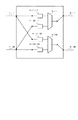
本実施例は、図2に示すように、複数の方路からそれぞれ到着するパケットを蓄積する複数のバッファ14−1〜14−MKと、この複数のバッファ14−1〜14−MKから読み出されるパケットをそのパケットの宛先毎の方路に振り分けるクロスポイントスイッチ15と、異なるバッファから同一読出しタイミングで読み出される異なるパケット同士の衝突を回避する制御信号をクロスポイントスイッチ15に与えるM×Mスケジューラ11−1〜11−L、12とを備えたパケットスイッチ20である。
【0029】
ここで、本実施例の特徴とするところは、複数のスケジューラ11−1〜11−L、12を備え、バッファ14−1〜14−Mに蓄積されたパケットの転送予定の経路となるクロスポイントスイッチ15における入力回線と出力回線との1以上の組合せが一つのスケジューリンググループに属する入力回線および出力回線と定義され、スケジューラ11−1〜11−L毎に、一つのスケジューリンググループに属する入力回線および出力回線を経路とするパケットの読出しスケジュールの制御を割当てる振り分け機能13を備え、クロスポイントスイッチ15は、1個のクロスポイントスイッチにより構成され、それぞれのスケジューラ11−1〜11−Lに割当てられたスケジューリンググループに属する前記入力回線と前記出力回線とのクロスポイントの接断を個々のスケジューラ11−1〜11−Lの制御にしたがいそれぞれ個別に制御するところにある。
【0030】
クロスポイントスイッチ15は、1個のクロスポイントスイッチにより構成され、このクロスポイントスイッチ15は、一つのスケジューリンググループに属するM本の入力回線および出力回線をK系統収容可能なMK本の入力回線および出力回線を備え、スケジューラ11−1〜11−Lは、L(L<K)個備えられる。
【0031】
以下では、本実施例をさらに詳細に説明する。
【0032】
図1に示すように、入力回線1−1〜1−MK、出力回線2−1〜2−MK、M入力M出力スイッチである第一段スイッチ10−1〜10−K、第三段スイッチ30−1〜30−Kおよび本実施例のパケットスイッチ20から構成される。第一段スイッチ10−1〜10−Kは、入力回線1−1〜1−MKから入力されるトラヒックを分散して第二段スイッチである本実施例のパケットスイッチ20に入力する。本実施例のパケットスイッチ20は、パケットの行き先を決定してスケジューリングを行う。第三段スイッチ30−1〜30−Kは、パケットスイッチ20から出力されたパケットを特定のポートに集めて出力回線2−1〜2−MKに出力する。
【0033】
図2は、パケットスイッチ20を構成する例を示す図である。パケットスイッチ20は、(MK×MK)クロスポイントスイッチ15、(M×M)スケジューラ11−1〜11−L、(M(K−L)×M(K−L))半固定制御機能12、振り分け機能13、バッファ14−1〜14−MKから構成される。
【0034】
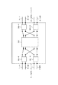
図3はパケットスイッチ20の動作を説明する図であり、M=K=2とする。すなわち、6×6スイッチであるパケットスイッチ20は、(6入力6出力)クロスポイントスイッチ15と(2×2)スケジューラ11−1、11−2および(2×2)半固定制御機能12、振り分け機能13から構成される。
【0035】
図3(a)に示すように、スケジューリンググループ#1に入力回線I−3およびI−4と出力回線O−2およびO−5が属し、スケジューリンググループ#2に入力回線I−1およびI−5と出力回線O−1およびO−6が属し、残りの入力回線I−2、I−6と出力回線O−3、O−4は半固定制御グループに属するとする。
【0036】
各バッファ14−1〜14−6とスケジューラ11−1、11−2の間は振り分け機能13により接続される。このとき、スケジューリンググループ#1に属する入力回線I−3、I−4および出力回線O−2、O−5は、スケジューラ11−1に、スケジューリンググループ#2に属する入力回線I−1、I−5および出力回線O−1、O−6は、スケジューラ11−2に、その他の回線は半固定制御機能12に接続する。
【0037】
この構成において、スケジューリンググループ#1に属する入力回線I−3、I−4と出力回線O−2、O−5の間のON/OFFスイッチの制御は、(2×2)スケジューラ11−1により行われ、論理的に1つの入力バッファ型スイッチを構成する。
【0038】
同様に、スケジューリンググループ#2に属する入力回線I−1、I−5と出力回線O−1、O−6との間のON/OFFスイッチの制御は、(2×2)スケジューラ11−2により行われ論理的に1つの入力バッファ型スイッチを構成する。半固定制御グループに属する入力回線I−2、I−6と出力回線O−3、O−4の間のON/OFFは、(2×2)半固定制御機能12により行われ論理的な回線交換が行われる。
【0039】
スケジューリンググループの構成は変更可能となる。例えば、図3(b)に示すように、スケジューリンググループ#1に入力回線I−2、I−3と出力回線O−2、O−3が属し、スケジューリンググループ#2に入力回線I−5、I−6および出力回線O−4、O−6が属するように変更可能となる。
【0040】
また、M(K−L)×M(K−L)の半固定制御機能12を、あらかじめL=2〜K−1まで可変可能とすることにより、動的なスケジューリングを行うスケジューラ11−1〜11−Lの数を可変にすることも可能である。
【0041】
また、MK×MKクロスポイントスイッチ15を、M×Mのクロスポイントスイッチを組み合わせて実現することにより、図2のMK×MKスイッチのK値を可変にすることが可能となる。
【0042】
【発明の効果】
以上説明したように、本発明によれば、単位スイッチおよびスケジューラの数を削減することにより、コストを削減することができるパケットスイッチを実現することができる。
【図面の簡単な説明】
【図1】本実施例のパケットスイッチを用いたスイッチの全体構成図。
【図2】本実施例のパケットスイッチの構成図。
【図3】本実施例のパケットスイッチの動作を説明するための図。
【図4】従来の出力バッファ型パケットスイッチの構成図。
【図5】従来の入力バッファ型パケットスイッチの構成図。
【図6】MK回線の入力バッファ型スイッチの構成図。
【図7】従来の三段クロススイッチの構成図。
【符号の説明】
1−1〜1−MK、I−1〜I−6 入力回線
2−1〜2−MK、O−1〜O−6 出力回線
3−1〜3−M 多重化部
4−1−1〜4−M−M 出力バッファ
6−1〜6−M、14−1〜14−MK 入力バッファ
7、11−1〜11−L、17 スケジューラ
8、15、18 クロスコネクトスイッチ
8−1−1〜8−M−1 ON/OFFスイッチ
10−1〜10−K 一段目スイッチ
12 半固定制御機能
13 振り分け機能
20 パケットスイッチ
20−1〜20−K 二段目スイッチ
30−1〜30−K 三段目スイッチ[0001]
BACKGROUND OF THE INVENTION
The present invention is used for a data transfer network. The present invention relates to a packet collision avoidance control technique used in a packet storage and exchange system.
[0002]
[Prior art]
A conventional output buffer type packet switch configuration will be described with reference to FIG. 4 (see, for example, Patent Document 1). Input lines 1-1 to 1-M, output lines 2-1 to 2-M, multiplexing units 3-1 to 3-M, and buffers 4-1-1 to 4-MM are configured.
[0003]
Packet data received from the input line 1-k is transferred to the buffers 4-k-1, 4-k-2,..., 4-k-M. Each buffer refers to information in the header portion of the packet data, determines whether or not to be incorporated into the buffer, and accumulates in the buffer when it is determined that the buffer is to be incorporated. If the packet is stored in any of the buffers 4-1-k, 4-2-k,..., 4-Mk connected to the multiplexing unit, the multiplexing unit 3-k Packet information is read from the buffer and transferred to the output line 2-k.
[0004]
When packet information is simultaneously stored in a plurality of buffers, a buffer to be read is determined by a round robin method or the like and transferred to an output line.
[0005]
Such a system is an output buffer system, but when the number of input lines is increased by using this system, there is a problem that the number of buffers increases.
[0006]
A conventional input buffer type switch configuration will be described with reference to FIG. Input lines 1-1 to 1-M, output lines 2-1 to 2-M, buffers 6-1 to 6-M, an M ×
[0007]
Packet data received from the input line 1-k is stored in the buffer 6-k. When the packet is accumulated in the buffer, the destination line information of the packet is notified to the
[0008]
When a packet exists in a plurality of buffers, each of the plurality of buffers notifies the scheduler of the output line information of the packet. When a different output line is notified, the switch connecting each buffer and the output line is turned ON. When the same output line is notified, a buffer having priority is selected by the round robin method or the like, and a switch for connecting the selected buffer and the output line is turned ON.
[0009]
This method is an input buffer type switch. In this method, when the number of input lines is increased, the rate of increase in the number of buffers can be reduced as compared with the output buffer type switch. Increasing is a problem.
[0010]
[Patent Document 1]
Japanese Patent Laid-Open No. 10-336241
[Problems to be solved by the invention]
Problems of such a conventional input buffer type switch will be described. FIG. 6 is a diagram in which the number of input lines is increased by K times in the input buffer type switch. At this time, the (MK × MK)
[0012]
Therefore, as shown in FIG. 7, an MK input MK output switch (M> K) is configured using an M input M output switch (see, for example, Patent Document 1). That is, the MK input and MK output switches include input lines 1-1 to 1-MK, output lines 2-1 to 2-MK, first stage switches 10-1 to 10-K, and second stage switches 20-1 to 20-20. -K and third stage switches 30-1 to 30-K.
[0013]
The first stage switch, second stage switch, and third stage switch are all M-input M-output switches. Now formula a <M / K> + (K−a) << M / K >> = M
(Where <X> is the smallest integer greater than or equal to X, << X >> is the smallest integer less than or equal to X)
Is established, <M / K> lines are connected between the first stage switch 10-1 and the second stage switches 20-1 to 20-a, and from the first stage switch 10-1 to the other stages. Connect "M / K" lines between the two-stage switches. <M / K> lines are connected between the first stage switch 10-2 and the second stage switches 20-2 to 20- (a + 1), and <M / K> lines are connected between the other second stage switches. Connect. Connect the following in the same way. Similarly, the second stage switch and the third stage switch are connected.
[0014]
Packets arriving at the first stage switch from the input line are distributed to the second stage switch according to the destination. At this time, the packet group has a traffic volume with respect to the second stage switches 20-1 to 20-K. Sort by using the hash method so that the ratio of the number of connected lines is the same. That is, the first stage switches 10-1 to 10-K distribute the traffic input from the input lines 1-1 to 1-MK and input to the second stage switches 20-1 to 20-K. The second stage switches 20-1 to 20-K determine the destination of the packet and perform scheduling. The third stage switches 30-1 to 30-K collect the packets output from the second stage switches 20-1 to 20-K to specific ports and output them to the output lines 2-1 to 2-MK.
[0015]
As described above, the method of realizing a large-scale switch with a three-stage switch configuration has a problem that the number of unit switches increases. The second stage switches 20-1 to 20-K are each provided with a scheduler, and it is necessary to prepare a relatively high-cost scheduler for the number of unit switches of the second stage switch.
[0016]
An object of the present invention is to provide a packet switch that can reduce the cost by reducing the number of unit switches and schedulers.
[0017]
[Means for Solving the Problems]
The present invention is characterized in that a plurality of schedulers are used for one crosspoint switch. As a result, in one scheduler, the processing load is too large and processing delay becomes a problem. However, since processing can be distributed to multiple schedulers, processing delay can be avoided and one crosspoint switch can be used. A large-scale packet switch can be configured. Thereby, it is possible to realize a packet switch capable of reducing the cost by reducing the number of unit switches.
[0018]
In addition, the number of schedulers to be provided is not necessarily the maximum number that can be considered, and can be reduced within a range that does not affect the actual processing. By reducing the number of relatively expensive schedulers, the cost can be reduced. It can be greatly reduced.
[0019]
That is, the present invention provides a plurality of buffers for accumulating packets arriving from a plurality of routes, switching means for distributing packets read from the plurality of buffers to routes for each destination of the packets, and different buffers. The packet switch includes scheduling means for giving the switching means a control signal for avoiding collision between different packets read at the read timing.
[0020]
Here, a feature of the present invention is that the scheduling unit includes a plurality of schedulers, and one or more of an input line and an output line in the switching unit serving as a path to transfer packets stored in the buffer. Is defined as an input line and an output line belonging to one scheduling group, and each scheduler has means for allocating control of a packet read schedule routed through an input line and an output line belonging to one scheduling group, The switching means is constituted by one crosspoint switch, and the connection of the crosspoint between the input line and the output line belonging to the scheduling group assigned to each scheduler is controlled by the individual scheduler. That It is located at having means for individually controlling.
[0021]
The switching means is composed of one crosspoint switch, and this crosspoint switch has MK input lines and outputs capable of accommodating K input lines and output lines belonging to one scheduling group. It is preferable that a line is provided, and that L (L <K) scheduling means are provided.
[0022]
As a result, the number of unit switches can be reduced, and the number of schedulers can be set to L (L <K), thereby reducing the cost of the packet switch. If the number of schedulers is set to L, when all K scheduling groups are scheduled simultaneously, a scheduling group that cannot be assigned by the scheduler occurs. However, the probability of such a situation occurring is generally very low. Further, even if the scheduling process is performed on the L scheduling groups at the same time, and the remaining (K-L) scheduling groups are then subjected to the scheduling process, it is unlikely that a practical delay will occur. Therefore, in the present invention, the cost can be reduced by reducing the number of schedulers having the highest cost among the packet switches.
[0023]
In addition, even if there are L schedulers, if a semi-fixed control function for semi-fixing scheduling processing of (K-L) scheduling groups is provided, scheduling that satisfies the semi-fixed scheduling processing is satisfied. By assigning a group to this semi-fixed control function, K scheduling groups can be simultaneously scheduled. Also in this case, the cost of the semi-fixed control function can be reduced because the cost of the semi-fixed control function is lower than that of the scheduler.
[0024]
Alternatively, the switching means may comprise a combination of a plurality of crosspoint switches, and may comprise means for changing the number of input lines and the number of output lines by switching the rest or operation state of each crosspoint switch.
[0025]
According to this, even if the number of input lines and the number of output lines change, it can be handled by the same device. In this case, a plurality of unit switches are used, but it is not necessary to use K units as in the past, and the number of unit switches should be smaller than the number of unit switches used in the conventional input buffer type packet switch. And cost reduction can be achieved.
[0026]
Further, at this time, scheduling for avoiding packet collision is performed by switching at least some of the paused or operating states of the plurality of schedulers corresponding to the number of input lines and the number of output lines changed by the changing unit. It is desirable to provide a means for changing the capability.
[0027]
DETAILED DESCRIPTION OF THE INVENTION
A packet switch according to an embodiment of the present invention will be described with reference to FIGS. FIG. 1 is an overall configuration diagram of the packet switch of this embodiment. FIG. 2 is a diagram showing the MK × MK switch configuration of the packet switch of this embodiment. FIG. 3 is a diagram for explaining the operation of the packet switch of this embodiment.
[0028]
In the present embodiment, as shown in FIG. 2, a plurality of buffers 14-1 to 14 -MK that accumulate packets respectively arriving from a plurality of routes, and the plurality of buffers 14-1 to 14 -MK are read. A
[0029]
Here, a feature of the present embodiment is that it includes a plurality of schedulers 11-1 to 11 -L, 12, and is a crosspoint serving as a route for transferring packets accumulated in the buffers 14-1 to 14 -M. One or more combinations of input lines and output lines in the
[0030]
The
[0031]
Hereinafter, this embodiment will be described in more detail.
[0032]
As shown in FIG. 1, input lines 1-1 to 1-MK, output lines 2-1 to 2-MK, first-stage switches 10-1 to 10-K which are M-input M-output switches, third-stage switches 30-1 to 30-K and the
[0033]
FIG. 2 is a diagram illustrating an example of configuring the
[0034]
FIG. 3 is a diagram for explaining the operation of the
[0035]
As shown in FIG. 3A, the input lines I-3 and I-4 and the output lines O-2 and O-5 belong to the
[0036]
Each buffer 14-1 to 14-6 and the schedulers 11-1 and 11-2 are connected by the
[0037]
In this configuration, the ON / OFF switch between the input lines I-3 and I-4 and the output lines O-2 and O-5 belonging to the
[0038]
Similarly, the ON / OFF switch between the input lines I-1 and I-5 and the output lines O-1 and O-6 belonging to the
[0039]
The configuration of the scheduling group can be changed. For example, as shown in FIG. 3B, the input lines I-2 and I-3 and the output lines O-2 and O-3 belong to the
[0040]
In addition, the scheduler 11-1 that performs dynamic scheduling by making the
[0041]
Further, by realizing the MK ×
[0042]
【The invention's effect】
As described above, according to the present invention, a packet switch capable of reducing costs can be realized by reducing the number of unit switches and schedulers.
[Brief description of the drawings]
FIG. 1 is an overall configuration diagram of a switch using a packet switch according to an embodiment.
FIG. 2 is a configuration diagram of a packet switch according to the embodiment.
FIG. 3 is a diagram for explaining the operation of the packet switch according to the embodiment;
FIG. 4 is a configuration diagram of a conventional output buffer type packet switch.
FIG. 5 is a configuration diagram of a conventional input buffer type packet switch.
FIG. 6 is a configuration diagram of an input buffer type switch of an MK line.
FIG. 7 is a configuration diagram of a conventional three-stage cross switch.
[Explanation of symbols]
1-1 to 1-MK, I-1 to I-6 Input lines 2-1 to 2-MK, O-1 to O-6 Output lines 3-1 to 3-M Multiplexing unit 4-1-1 to 1-1 4-MM output buffers 6-1 to 6-M, 14-1 to 14-MK input buffers 7, 11-1 to 11-L, 17
Claims (3)
前記バッファに蓄積されたパケットの転送予定の経路となる前記スイッチング手段における入力回線と出力回線との1以上の組合せが一つのスケジューリンググループに属する入力回線および出力回線と定義され、
前記スイッチング手段は、1個のクロスポイントスイッチを含んで構成され、
このクロスポイントスイッチは、一つのスケジューリンググループに属するM本の入力回線および出力回線をK系列収容可能なMK本の入力回線および出力回線を備え、
前記スケジューリング手段は、前記Kより少ない複数L個のスケジューラを備えて、各スケジューラ毎に一つのスケジューリンググループを割り当てる手段を備え、
前記スケジューラは、割り当てられた一つのスケジューリンググループに属する入力回線および出力回線を経路とするパケットの読出しスケジュールの制御を行う手段を備え、
前記スイッチング手段は、それぞれの前記スケジューラに割当てられたスケジューリンググループに属する前記入力回線と前記出力回線とのクロスポイントの接断を個々の前記スケジューラの制御にしたがいそれぞれ個別に制御する手段を備え、
前記スケジューリング手段は、(K−L)個のスケジューリンググループのスケジューリングを、予め定められた論理でのスケジューリング、またはL個のスケジューリンググループのスケジューリング処理後のスケジューリング処理に振り分ける手段を備えた
ことを特徴とするパケットスイッチ。A plurality of buffers for accumulating packets arriving from a plurality of routes, a switching means for distributing packets read from the plurality of buffers to a route for each destination of the packets, and different data read from different buffers at the same read timing In a packet switch comprising scheduling means for giving a control signal for avoiding collision between packets to the switching means,
One or more combinations of an input line and an output line in the switching means serving as a transfer scheduled path of the packet stored in the buffer are defined as an input line and an output line belonging to one scheduling group ,
The switching means is configured to include one crosspoint switch,
This crosspoint switch has MK input lines and output lines that can accommodate K series of M input lines and output lines belonging to one scheduling group,
The scheduling means comprises means for allocating one scheduling group for each scheduler , comprising a plurality of L schedulers less than the K ,
The scheduler includes means for controlling a packet read schedule that takes an input line and an output line belonging to one assigned scheduling group as routes.
The switching means comprises means for individually controlling the connection / disconnection of the input line and the output line belonging to the scheduling group assigned to each scheduler according to the control of each scheduler;
The scheduling means comprises means for allocating scheduling of (K-L) scheduling groups to scheduling with a predetermined logic or scheduling processing after scheduling processing of L scheduling groups. Packet switch to do.
個々のクロスポイントスイッチの休止または稼働の状態を切り替えることにより入力回線数および出力回線数を変更する手段を備えた
請求項1記載のパケットスイッチ。 The switching means is constituted by a combination of a plurality of crosspoint switches,
2. The packet switch according to claim 1, further comprising means for changing the number of input lines and the number of output lines by switching a pause or operation state of each crosspoint switch.
Priority Applications (1)
| Application Number | Priority Date | Filing Date | Title |
|---|---|---|---|
| JP2002338319A JP3878112B2 (en) | 2002-11-21 | 2002-11-21 | Packet switch |
Applications Claiming Priority (1)
| Application Number | Priority Date | Filing Date | Title |
|---|---|---|---|
| JP2002338319A JP3878112B2 (en) | 2002-11-21 | 2002-11-21 | Packet switch |
Publications (2)
| Publication Number | Publication Date |
|---|---|
| JP2004173098A JP2004173098A (en) | 2004-06-17 |
| JP3878112B2 true JP3878112B2 (en) | 2007-02-07 |
Family
ID=32701578
Family Applications (1)
| Application Number | Title | Priority Date | Filing Date |
|---|---|---|---|
| JP2002338319A Expired - Fee Related JP3878112B2 (en) | 2002-11-21 | 2002-11-21 | Packet switch |
Country Status (1)
| Country | Link |
|---|---|
| JP (1) | JP3878112B2 (en) |
-
2002
- 2002-11-21 JP JP2002338319A patent/JP3878112B2/en not_active Expired - Fee Related
Also Published As
| Publication number | Publication date |
|---|---|
| JP2004173098A (en) | 2004-06-17 |
Similar Documents
| Publication | Publication Date | Title |
|---|---|---|
| AU675302B2 (en) | Output-buffer switch for asynchronous transfer mode | |
| JP2923693B2 (en) | Large capacity ATM switch | |
| US5550815A (en) | Apparatus and method for reducing data losses in a growable packet switch | |
| KR100396109B1 (en) | Terabit per second atm packet switch having out-of-band control with multicasting | |
| US7173931B2 (en) | Scheduling the dispatch of cells in multistage switches | |
| US20020044546A1 (en) | Methods and apparatus for managing traffic through a buffered crossbar switch fabric | |
| JPH10285186A (en) | Atm switch queuing system | |
| CA2112528A1 (en) | Packet Switching System for Forwarding Packets from Input Buffers Using Idle/Busy Status of Output Buffers | |
| JPH05207062A (en) | Packet switching system | |
| EP0724798A1 (en) | Selective congestion control mechanism for information networks | |
| EP0323835A2 (en) | Packet concentrator and switch including a controller for assigning priorities to space switch input terminals for control of buffers | |
| JPH10285187A (en) | Distributed buffering system for atm switch | |
| JPH08307432A (en) | Communication method | |
| JP3816314B2 (en) | Packet switching equipment | |
| Doi et al. | A high-speed ATM switch with input and cross-point buffers | |
| US20030193943A1 (en) | Controlled shared memory smart switch system | |
| JP2002325087A (en) | Unblocked switch system, its switching method and program | |
| JP3878112B2 (en) | Packet switch | |
| US7672301B2 (en) | Distribution stage for enabling efficient expansion of a switching network | |
| EP0739093B1 (en) | High-speed switch and high-speed switching method | |
| US7046626B2 (en) | Switching devices | |
| KR0167901B1 (en) | Asynchronous transfer mode switch | |
| JP2695916B2 (en) | Cell switch | |
| JPH05260071A (en) | Asynchronous time division multiplex transmission equipment provided with switch element | |
| US20040120338A1 (en) | Multi-functional switch fabric apparatus and control method for the same |
Legal Events
| Date | Code | Title | Description |
|---|---|---|---|
| A621 | Written request for application examination |
Free format text: JAPANESE INTERMEDIATE CODE: A621 Effective date: 20041222 |
|
| A131 | Notification of reasons for refusal |
Free format text: JAPANESE INTERMEDIATE CODE: A131 Effective date: 20060704 |
|
| A521 | Written amendment |
Free format text: JAPANESE INTERMEDIATE CODE: A523 Effective date: 20060829 |
|
| TRDD | Decision of grant or rejection written | ||
| A01 | Written decision to grant a patent or to grant a registration (utility model) |
Free format text: JAPANESE INTERMEDIATE CODE: A01 Effective date: 20061031 |
|
| A61 | First payment of annual fees (during grant procedure) |
Free format text: JAPANESE INTERMEDIATE CODE: A61 Effective date: 20061101 |
|
| FPAY | Renewal fee payment (event date is renewal date of database) |
Free format text: PAYMENT UNTIL: 20101110 Year of fee payment: 4 |
|
| FPAY | Renewal fee payment (event date is renewal date of database) |
Free format text: PAYMENT UNTIL: 20101110 Year of fee payment: 4 |
|
| FPAY | Renewal fee payment (event date is renewal date of database) |
Free format text: PAYMENT UNTIL: 20111110 Year of fee payment: 5 |
|
| FPAY | Renewal fee payment (event date is renewal date of database) |
Free format text: PAYMENT UNTIL: 20111110 Year of fee payment: 5 |
|
| FPAY | Renewal fee payment (event date is renewal date of database) |
Free format text: PAYMENT UNTIL: 20121110 Year of fee payment: 6 |
|
| LAPS | Cancellation because of no payment of annual fees |