JP3874799B2 - Coated substrate drying system - Google Patents
Coated substrate drying system Download PDFInfo
- Publication number
- JP3874799B2 JP3874799B2 JP51275097A JP51275097A JP3874799B2 JP 3874799 B2 JP3874799 B2 JP 3874799B2 JP 51275097 A JP51275097 A JP 51275097A JP 51275097 A JP51275097 A JP 51275097A JP 3874799 B2 JP3874799 B2 JP 3874799B2
- Authority
- JP
- Japan
- Prior art keywords
- substrate
- condensing
- condensate
- condensation
- liquid
- Prior art date
- Legal status (The legal status is an assumption and is not a legal conclusion. Google has not performed a legal analysis and makes no representation as to the accuracy of the status listed.)
- Expired - Fee Related
Links
Images


Classifications
-
- F—MECHANICAL ENGINEERING; LIGHTING; HEATING; WEAPONS; BLASTING
- F26—DRYING
- F26B—DRYING SOLID MATERIALS OR OBJECTS BY REMOVING LIQUID THEREFROM
- F26B25/00—Details of general application not covered by group F26B21/00 or F26B23/00
- F26B25/005—Treatment of dryer exhaust gases
- F26B25/006—Separating volatiles, e.g. recovering solvents from dryer exhaust gases
-
- F—MECHANICAL ENGINEERING; LIGHTING; HEATING; WEAPONS; BLASTING
- F26—DRYING
- F26B—DRYING SOLID MATERIALS OR OBJECTS BY REMOVING LIQUID THEREFROM
- F26B13/00—Machines and apparatus for drying fabrics, fibres, yarns, or other materials in long lengths, with progressive movement
- F26B13/10—Arrangements for feeding, heating or supporting materials; Controlling movement, tension or position of materials
- F26B13/105—Drying webs by contact with heated surfaces other than rollers or drums
-
- F—MECHANICAL ENGINEERING; LIGHTING; HEATING; WEAPONS; BLASTING
- F26—DRYING
- F26B—DRYING SOLID MATERIALS OR OBJECTS BY REMOVING LIQUID THEREFROM
- F26B25/00—Details of general application not covered by group F26B21/00 or F26B23/00
-
- F—MECHANICAL ENGINEERING; LIGHTING; HEATING; WEAPONS; BLASTING
- F26—DRYING
- F26B—DRYING SOLID MATERIALS OR OBJECTS BY REMOVING LIQUID THEREFROM
- F26B3/00—Drying solid materials or objects by processes involving the application of heat
- F26B3/18—Drying solid materials or objects by processes involving the application of heat by conduction, i.e. the heat is conveyed from the heat source, e.g. gas flame, to the materials or objects to be dried by direct contact
- F26B3/20—Drying solid materials or objects by processes involving the application of heat by conduction, i.e. the heat is conveyed from the heat source, e.g. gas flame, to the materials or objects to be dried by direct contact the heat source being a heated surface, e.g. a moving belt or conveyor
-
- F—MECHANICAL ENGINEERING; LIGHTING; HEATING; WEAPONS; BLASTING
- F26—DRYING
- F26B—DRYING SOLID MATERIALS OR OBJECTS BY REMOVING LIQUID THEREFROM
- F26B7/00—Drying solid materials or objects by processes using a combination of processes not covered by a single one of groups F26B3/00 and F26B5/00
- F26B7/002—Drying solid materials or objects by processes using a combination of processes not covered by a single one of groups F26B3/00 and F26B5/00 using an electric field and heat
-
- G—PHYSICS
- G11—INFORMATION STORAGE
- G11B—INFORMATION STORAGE BASED ON RELATIVE MOVEMENT BETWEEN RECORD CARRIER AND TRANSDUCER
- G11B5/00—Recording by magnetisation or demagnetisation of a record carrier; Reproducing by magnetic means; Record carriers therefor
- G11B5/84—Processes or apparatus specially adapted for manufacturing record carriers
- G11B5/842—Coating a support with a liquid magnetic dispersion
- G11B5/845—Coating a support with a liquid magnetic dispersion in a magnetic field
Landscapes
- Engineering & Computer Science (AREA)
- Mechanical Engineering (AREA)
- General Engineering & Computer Science (AREA)
- Textile Engineering (AREA)
- Chemical & Material Sciences (AREA)
- Microbiology (AREA)
- Life Sciences & Earth Sciences (AREA)
- Dispersion Chemistry (AREA)
- Drying Of Solid Materials (AREA)
- Application Of Or Painting With Fluid Materials (AREA)
- Coating Apparatus (AREA)
- Manufacturing Of Magnetic Record Carriers (AREA)
- Cleaning Or Drying Semiconductors (AREA)
- Exposure And Positioning Against Photoresist Photosensitive Materials (AREA)
- Exposure Of Semiconductors, Excluding Electron Or Ion Beam Exposure (AREA)
Abstract
Description
技術分野
本発明は、質量およびエネルギーを輸送し、基材上のコーティングを乾燥するための方法および装置に関する。厳密には、本発明は、包囲された領域内で質量およびエネルギーを輸送することと、基材を乾燥させることとに関する。
背景技術
ウェブなど、コーティングされた基材を乾燥するには、コーティングにエネルギーを供給し、次に蒸発した液体を除去しなければならない。コーティングから蒸発させられる液体は、有機溶剤系や、水性溶剤系を含む無機系などの溶剤を含む任意の液体であっても良い。対流、伝導、輻射、およびマイクロ波エネルギーがコーティングされたウェブにエネルギーを供給するために使用される。適用された対流、または強制的に送られた気体流が、蒸発した液体を除去するために使用される。適用された対流は、電力の入力によって生成され、計画的に起こされた対流として定義される。これは、ウェブの運動によりまれに起こる対流、自然対流、および他の避けがたい力は除外する。水蒸気など、蒸気が非毒性である場合には、その蒸気は、周囲環境に急速蒸発させることによって取り除かれる。
対流乾燥技術では、大量の、不活性、またはそうではない気体が、気体/液体界面から蒸発した液体を除去するのに必要となる。これらの乾燥法は、乾燥される被覆ウェブと乾燥容器の上部との間に大きな空間が、大量の気体流を与えるために必要となる。乾燥は、特に、気体/液体界面における拡散、対流、移動ウェブからの境界層空気および衝突空気の流れ、蒸気濃度、および液体−蒸気状態変化対流などの要因によって決定される。これらの現象は、被覆されたウェブのすぐ上で、典型的に表面から15cm以内のところで起こる。従来の乾燥法は被覆されたウェブ上に広い空間を有し、それらは全気体流の平均速度と温度しか制御できないので、それらは、気体/液体界面近辺でのこれらの現象を制御する能力に限界があった。
有機溶剤系の場合、これらの全気体流の蒸気濃度は、低く、典型的に1〜2%に保たれて、蒸気/気体混合物の引火限界以下に留める。これらの大量の気体流は、処理過程から蒸発した液体を取り除くためのものである。これらの気体を封じ込め、加熱し、加圧するのに掛かる費用は、乾燥コストの大部分を占めることとなる。これらの大量の気体流を不要にすることができれば好都合となる。
これらの気体流は、大規模熱交換器、または拭いブレードを備えたチルドロールを使用して、排出前に凝縮システムに導かれて、蒸気を抽出することができる。これらの凝縮システムは、全気体流内の被覆ウェブから比較的遠く離れたところに設置される。この気体流が低蒸気濃度であるために、これらのシステムは、大規模、且つ高価であり、低温で操作されなければならない。
蒸気濃度が高い、被覆された基材に近いところにこの凝縮システムを配置できれば好都合である。但し、従来の熱交換器は、それらが傾けて設置されていない、あるいは回収容器を備えていなかった場合、重力によって、凝縮された液体を被覆表面上に再度排出し、製品の品質に悪影響を及ぼすこととなる。それらが回収容器を備えていた場合、それらは高濃度ウェブ表面から単離されることとなる。それらが傾けて設置されていた場合でも、滴のしたたりが尚も問題となろう。従来の熱交換器は、ウェブ通路をたどって、乾燥条件を制御するように平面的でもない。
米国特許第4,365,423号では、乾燥されるウェブ上の小孔表面を利用して、大量の気体流によって生成される乱れからコーティングを遮蔽して、まだらとなるのを防止する乾燥システムが記載されている。但し、このシステムは、適用された対流を排除せず、二次的低効率溶剤回収法を用いる必要があり、乾燥速度を低減した。乾燥速度が低減したため、この発明は、乾燥長の5〜25%のみにこの遮蔽を利用することを教示する。
独国特許公報第4009797号では、蒸発した液体を除去するために乾燥容器内に配置された溶剤回収システムを開示している。拭いブレードを備えたチルドロールは、ウェブ表面の上に配置され、液状の蒸気を除去する。適用された対流は、蒸発した液体を何も除去しない。但し、このロールは、乾燥器長の一部の短い区域の表面に近接した高蒸気濃度内においてのみ有効である。これは、気体/液体界面における条件の最適制御を提供しない。事実、このロールが回転すると、ウェブ表面の近くに乱れを起こし得る。このシステムは、乾燥システム内を移動する際にその形状を被覆されるウェブの一連の平坦な表面に適応することもできない。故に、このシステムは、小さな平面ギャップで動作して乾燥条件を制御することができず、最適な凝縮効率を達成することができない。
英国特許第1 401 041号では、被覆される基材に近接した加熱および凝縮プレートを使用することによって従来乾燥法では必要とされる大量の気体流を利用しないで動作する溶剤回収システムを開示している。このシステムは、重力のみを利用して凝縮表面から液体を除去する。故に、この凝縮表面は、重力が被覆された基材上に凝縮された液体を戻すので、被覆基材の上に配置できない。図面、および説明(3頁、89〜92行目)では、凝縮表面は、凝縮表面の上に、垂直な、または被覆された面が下向きとなった状態の被覆基材で開示されている。基材の底面にコーティングを施す、またはコーティング後に基材を反転させることは、工業界では好適な方法であるとは言えない。反転させた姿勢でのコーティング、および乾燥前に被覆された基材を反転すると、コーティング不良となり得る。これらの限界は、方法に関わる柔軟性を非常に減じ、それを標準の製造法に適応させるにかなりの費用が必要となる。垂直、または反転乾燥法のこの必要条件が、おそらく産業界でこの方法が採用、または議論されなかった理由のようである。
米国特許第1 401 041号では、2頁の126行目から3頁の20行目までで、凝縮表面上での液状膜層の成長、および滴形成が起こるこの方法の問題が開示されている。「結果としてできる液状膜14は、凝縮器の底端に向かって厚みが増す可能性がある」ので、凝縮表面の長さがこの液膜層の発達および安定性によって制限される。凝縮表面の長さを制限することは、乾燥器長を制限する、またはコーティングが未乾燥の状態で乾燥システムを出て行くことを求めることとなる。これは、幾分かの溶剤蒸気を周囲に散逸させ、乾燥現象の制御を損ない、不良品を生成すると言った、望ましくない効果を有する。その他の限界は、被覆された基材からの凝縮表面の距離を約5ミリメートル以下に保って、凝縮液状液膜が基材と接触するのを防止し、滴が基材に接触するのを防止するのが難しいからである。
垂直、または反転乾燥法に対するこのシステムの限界、乾燥器の長さの制限、および被覆された基材から所望の距離で動作する能力の欠落のため、それが所望の乾燥結果を達成するには不十分である。
気体/液体界面近辺の条件の制御を改善した、被覆された基材を乾燥するためのシステムへの要請があり、これは、蒸発した液体を輸送するために適用された対流の利用を不要にし、凝縮蒸気回収システムの効率を改善する。基材に近接した小さなギャップで動作できるシステムへの要請もある。
発明の開示
本発明は、質量およびエネルギーを輸送し、被覆された基材を乾燥する方法、および装置である。凝縮表面は、乾燥されている基材面(被覆面)の基材に近接して設置される。被覆された基材からの液体は、蒸発され、次に適用された対流を利用せずに、凝縮表面上で凝縮される。凝縮された液体は、凝縮表面から移動されるが、それは液体のままである。
凝縮液の液膜層は、凝縮表面上に生成されて、凝縮液の滴の形成、および基材への凝縮液の架橋を防止することができる。
凝縮表面は、基材から5mm未満の間隔を空けて配置できる。他の態様では、凝縮表面は、基材の上に設置できる。他の態様では、凝縮液体は、凝縮表面側縁部に向かって移動される。
凝縮された液体は、少なくとも部分的に重力を利用することによって、除去できる。凝縮表面は、被覆された基材の少なくとも一方の横側に傾かせることができる。重力は凝縮表面から凝縮液を移動する。凝縮された液体は、小孔材料を利用することによってなど、表面張力、または毛管現象の力を利用しても除去できる。
複数の凝縮表面も、使用できる。一方のものが、被覆基材の上に設置され、基材の少なくとも一方の横側に傾けられた凝縮プラテンであり、他方のものが、上部表面、および下部表面を有するシートである。これらのシートは、それらが凝縮プラテンの下部縁部に直面するそれらの下部縁部の水平位置からそれて傾斜されるように凝縮プラテンの下に設置できる。これらのシートは、互いに重複して、その重複領域で互いに間隔を空けて配置できる。
他の態様では、凝縮プラテンは、凝縮プレート、この凝縮プレートの下に、間隔を空けて配置された上部表面と下部表面とを有する小孔シートを有する。小孔シートの上部表面および下部表面は、凝縮表面を形成する。凝縮プラテンと小孔シートとの間の間隔幅、シート内の小孔のサイズ、および小孔シートの開口部分と中実部分との比は、表面張力を引き起こして凝縮表面上に凝縮液を保持するように選択できる。
乾燥速度は、ギャップ高さ、および被覆された基材と凝縮表面との間の温度差を制御することによって制御できる。
凝縮表面は、静止、または回転ベルト上に形成できる。代わりに、凝縮表面は、任意のタイプの平面、または溝付きプレート、チューブ、フィン、または他の形状から形成できる。凝縮表面は、凝縮液を保持するためにヤング・ラプラス表面張力を、それを移動するために毛管現象の力を利用する小孔プレートから形成できる。
凝縮表面が凝縮された液体を長手方向に流れさせる場合、収集システムが液体を捕集するのし使用できる、または凝縮表面上の基材が液体を導くことができる。凝縮表面上の、リブなど、構造物は、凝縮液の蓄積を制限でき、滴の形成を防ぐことができる。
【図面の簡単な説明】
第1図は、本発明の乾燥システムの斜視図である。
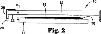
第2図は、第1図のシステムの端面図である。
第3図は、第1図の線3−3についての断面図である。
第4図は、本発明の他の実施例による乾燥システムの斜視図である。
第5図は、第4図のシステムの端面図である。
第6図は、本発明の他の実施例による乾燥システムの斜視図である。
第7図は、本発明の他の実施例による乾燥システムの断面図である。
第8図は、本発明の他の実施例による乾燥システムの断面図である。
第9図は、本発明の他の実施例による乾燥システムの断面図である。
第10図は、本発明の他の実施例による乾燥システムの略側面図である。
第11図は、本発明の他の実施例による乾燥システムの断面図である。
第12図は、本発明の他の実施例による凝縮プラテンの底面図である。
第13図は、本発明の他の実施例による乾燥システムの平面図である。
第14図は、本発明の他の実施例による乾燥システムの平面図である。
第15図は、本発明の他の実施例による乾燥システムの側面図である。
第16図は、処理変数を示す本発明の略側面図である。
発明を実施するための最良の形態
本発明のシステムは、コーティング表面の上に小さな制御された環境ギャップを与える凝縮表面を利用して、移動ウェブなどの、質量およびエネルギーを輸送し、被覆された基材上のコーティングを乾燥させるための方法、および装置である。化学反応、硬化、および相変化など、乾燥行程中に起こる他の物理的、および化学的現象も、本発明によって影響を受ける。
第1図、2図、3図の実施例では、乾燥「液体を加熱してそれを蒸気に蒸発させ、その蒸気をウェブから離れた遠くに輸送し、蒸気を凝縮し、凝縮された蒸気「凝縮液とも呼ばれる」をウェブから離れて遠くに輸送すること」は、従来の乾燥方法と関連した適用された気体の対流を必要とせずに起こる。これは、多くの精密コーティングと関連するまだらの形成を低減し、乾燥速度を増した乾燥を可能にする。第4〜15図の実施例では、少なくともウェブからの蒸発した液体の除去が、適用された気体の対流を利用せずに起こる。このシステムの全ての態様は、気体/液体界面近くで起こる現象についての制御の改善を達成し、高い液体回収効率を達成する。
態様の全ては、凝縮を利用して、適用された対流の力を必要としない実質的に平面であり、ここでは周囲、および境界対流の力が最小限に抑えられるギャップ内で蒸発した液体を除去する。この乾燥システムは、コーティング表面に近接して小さな制御された環境ギャップを与え、乾燥機構から適用された対流に対する必要条件を無くすことによって従来の乾燥技術と比べて多数の利点を有する。ある製品では、化学反応、または他の物理的および化学的作用が、乾燥中にコーティング内で起こる。この乾燥システムは、これらの作用がその工程内で進んでいるかどうかに関係なく機能する。この乾燥システムは、乾燥中これらの作用に影響を及ぼすことができる。その一例は、溶剤内に分散した、または溶解した湿分硬化重合体のものであり、乾燥雰囲気内に湿度があるために乾燥工程中に逆に影響を及ぼされる可能性がある。本発明は、コーティング表面の上に小さな制御した環境ギャップを与えることができるので、湿度を制御した乾燥雰囲気を提供してこれらの重合体の硬化を改善するのが実質的により簡単となる。乾燥現象の制御を改善し、被覆された表面の上に小さな制御した環境ギャップを与えることによって、乾燥工程中に起こる他の物理的、および化学的作用が利用できる数多くの用途がある。
代わりの方法では、乾燥システムは、適用された対流と組み合わせることができ、適用された対流は、コーティングを横切って、長手方向、横方向、またはその他任意の方向のいずれかに気体を強制的に送ることによって生成できる。これは、被覆された表面の上の雰囲気に追加的な質量移動、または他の修正を提供できる。この方法は、適用された対流が製品の性質を損なわないようなところで使用できる。
本発明者は、基材を乾燥するのに、顕著な乾燥の改善、および乾燥速度の増加は、凝縮表面から被覆された基材までの距離が5ミリメートル以下であるときに起こることを発見した。英国特許第1 401 041号のシステムは、乾燥制御についての大幅な改善がなされるような範囲では現実的に動作できない。
平面であるか無いか、多孔質であるか無いか、組織化されているか無いかに関係なく、任意のタイプのプレート、またはチューブ、またはフィンなど他の形状のものなどの、多種の凝縮構造が使用できる。凝縮表面構造は、巨視的規模、中規模、および微小規模の形状および寸法を組み合わせることができる。これらのプレートには、固定、または移動プラテン、液体スクレーパー付き、または無しの移動ベルト、および同様のシステムを含む。この凝縮構造は、ウェブと平行をなす、またはウェブと角度をなして設置でき、平面、または湾曲した表面を有することができる。
凝縮表面は、3つの基準を満たさなければならない。第1は、凝縮の潜熱を除去するのに十分なエネルギーの移動ができなければならない。第2は、凝縮液が少なくとも部分的に凝縮表面を湿らせなければならない。第3では、凝縮表面は、凝縮された蒸気(凝縮液)がウェブの被覆された表面に戻るのを防止しなければならない。凝縮表面に関連することは、液膜の不均質の兆候が現れる有効臨界凝縮液膜厚みである。この厚みは、凝縮液の物理的性質(表面張力、密度、および粘度など)だけでなく、凝縮表面材料、形状、寸法、外形、向き、構造、および他の要素の関数である。システムの他の特徴は、凝縮液の移動および除去である。これは、凝縮液の液膜厚みを有効臨界厚み未満に維持し、毛細管現象の力、重力、機械力、またはこれらの力の様々な組み合わせによって達成できる。
毛細管の力、または毛細管圧力は、湾曲したメニスカスで作用する表面張力の結果として説明でき、ヤング−ラプラス等式として知られる毛管現象の基礎的等式によって決定される。ヤング−ラプラス等式は、Δp=σ(1/R1+1/R2)であり、ここでΔpは界面での圧力降下、σは表面張力、R1およびR2は、界面の主曲率半径である。毛細管現象については、Adamson,A.W.の「Physical Chemistry of Surfaces,4th ed.」John Wiley & Sons,Inc.(1982)で詳述される。第1図、2図、4図、5図、9図、10図、11図は、他の力と共に、毛管現象の力を利用して、凝縮表面から凝縮液を除去する例を示す。
重力は、重力場における流体質量の位置に起因し、これは、静水落差である。第7図、8図、10図、12図は、他の力と共に、重力を利用して、凝縮表面から凝縮液を除去する例を示す。
他の機構は、凝縮表面から凝縮された液体を除去して凝縮された液体が基材に戻るのを防ぐために使用できる。例えば、ワイパー、ベルト、スクレーパー、ポンプシステム、または任意の組み合わせなどの機械的装置は、凝縮された液体を除去するために使用できる。第6図、13図、14図、15図は、他の力と共に、機械的力を利用して、凝縮表面から凝縮液を除去する例を示す。
第1図、2図、3図は、2つのプラテンを使用する装置を示す。第4図、5図は、1つのプラテンを使用する装置を示す。いずれの場合も、1つのプラテンは、ウェブの被覆された表面から短距離に配置された凝縮液移動表面を有する。15〜20cm未満の距離が好ましい。5mm未満の距離は、より好都合である。また、0.5mm未満の距離、および0.1mm以下の距離でも達成可能である。
第1図、2図では、装置10には、冷却でき、加熱されたプラテン14から間隔を空けて配置された凝縮プラテン12を含む。この凝縮プラテン12は、周囲温度よりも高い、または低い温度温度T1に設定され、加熱されたプラテン14は、周囲温度よりも高い、または低い温度温度T2に設定される。被覆されたウェブ16の温度はT3である。ウェブ位置は、h1およびh2によって定義され、ウェブ16、凝縮および加熱プラテンのそれぞれの対向表面間距離である。第16図は、これらの変数の相対的場所を示す。凝縮プラテンと任意の加熱プラテンとの間の総ギャップhは、h1、h2、および被覆されたウェブの厚みとの合計である。コーティング18を有するウェブ16は、2つのプラテン間で任意の速度で移動する。代わりに、ウェブが静止して、装置全体10が移動するか、またはウェブと装置の両方が移動するものであっても良い。これらのプラテンは、装置内で静止しているものである。加熱されたプラテン14は、ウェブ16の非被覆側に、ウェブと接触して、またはウェブとプラテンとの間に小さなギャップh2をもたせて設置される。凝縮プラテン12は、ウェブとプラテンとの間に小さなギャップh1をもたせて、ウェブ16の被覆側に設置される。凝縮プラテン12との加熱プラテン14とは、ウェブ16の上下両方に適用される対流を不要にする。乾燥は、温度T1、T2、および距離h1、h2を調整することによって制御される。
静止、または移動可能であっても良い凝縮プラテン12は、被覆表面に近接して配置される(10cm離して、5cm離して、またはそれよりも接近させて)。このようにこれらのプラテンを配置することで、被覆されたウェブに近接して小さなギャップを与える。このギャップは、実質的に一定であり、これは少量の収束、または発散を起こし得る。このギャップは、凝縮表面上のいかなる溝(後述の)にもかかわらず、実質的に一定である。これらプラテンの向きは、重要ではない。凝縮プラテン12は、ウェブの上に(第1図、2図、4図、および5図9図で示されるように)、ウェブの下に(ウェブの底部表面にコーティングがある場合には)あっても良く、この装置は、ウェブ移動方向の軸周りで傾けられることを含む、垂直の、またはその他の任意角度のウェブで動作できる。
この加熱されたプラテン14は、ウェブ16を通して加えられた対流を用いることなくコーティング18にエネルギーを供給して、コーティング18から液体を蒸発させてそのコーティングを乾燥させる。エネルギーは、高熱伝達速度を達成する伝導、輻射、および対流の組み合わせによって伝達される。これは、ウェブ16上のコーティング18内の液体を蒸発させる。コーティング18からの蒸発した液体は、次にウェブ16と凝縮プラテン12との間のギャップh1を横切って運ばれ(拡散および対流を利用して)、凝縮プラテン12の底部表面上で凝縮する。
第3に示されるように、凝縮プラテン12の底部表面は、凝縮表面22であり、毛細管現象を利用して凝縮された液体が重力によってコーティングに戻るのを防ぎ、凝縮された液体を縁のプレート26に向かって横方向に移動させる横断開口チャネル、まなわち溝24を有する。これらの溝は、三角形、方形、円形、またはその他のより複雑な形状、またはそれらの形状の組み合わせであっても良い。溝材料、形状、および寸法は、表面張力、粘度、および密度など、所望の質量流、および凝縮液の物理的性質に適応するように設計される。
特定タイプの凝縮表面は、コーナーを有する開口チャネル、すなわち溝を有するものである。例えば、第3図に示されたこのタイプの毛細管凝縮表面は、コンカス−フィン不均質{コンカス(Concus).Pおよびフィン(Finn).Rの「On the Behavior of a Capillary Surface in a Wedge」National Academy of Science会報、第63巻、292〜299頁(1969年)}を利用して設計され、これは、α+θs<90°であり、ここでαは任意のコーナー挟角の半分であり、θsは気体/液体/固体静的接触角である。この静的接触角は、気体状の所与表面材料に対する液体の表面張力によって決まる。不均質が満たされない場合、この界面は、制限され、不均質が満たされる場合、この界面は有限平衡位置を持たず、そのメニスカスは制限されない。この後者の場合、液体は毛細管現象によって、無限に、またはチャネル、すなわち溝の端部まで進む。コーナー角度で溝を付けた表面は、コーティング液が、水などの高表面張力を有するものである場合には有用である。コーナーを備えた毛細管表面は、Lopezde Ramos,A.L.の「Capillary Enhanced Diffusion of CO2 in Porous Media、」Ph.D.学位論文、タルサ大学(1993年)で詳述されている。
これら溝24は、長手方向、または任意のその他の方向であっても良い。これらの溝が長手方向にある場合、適当な収集システムが溝の端部に配置されて凝縮された液体が被覆された表面18に落下して戻るのを防ぐことができる。この実施例は、凝縮プレート12の長さを限定し、さらに最小ギャップh1をも限定する。
液体が溝24の端部に達すると、それは縁プレート26と凝縮表面22との間の角度で相交わる。液体メニスカスは、凝縮表面から少なくとも一方の縁プレートに凝縮液を引き寄せる低圧領域を形成する。重力は、メニスカス内の毛細管の力に打ち勝ち、液体は、液膜、または滴として縁プレート26の面に落流する。縁プレート26は、端に溝を備えただけのものではなく、任意の凝縮表面と共に使用できる。滴28は、各縁プレート26から落下し、収集システム(図示せず)に収集することができる。例えば、スロット付きパイプは、各縁プレート26の底端の周りに設置されて液体を収集し、それを容器に導くことができる。これらの縁プレート26は、明細書全体を通じて凝縮プラテンの凝縮表面の端部と接触しているものとして示される。但し、これらの縁プレートは、凝縮された液体を受けるのに機能的に十分接近している限り、凝縮プラテンに接触することなく、それらに近接して設置できる。
代わりに、凝縮された液体は、凝縮表面22から除去される、またはウェブ16に戻ることが少なくとも防止される限り、プラテンから全く除去される必要がない。これらの縁プレート26は、凝縮表面14と平行に配置されて示されているが、それらはその他の角度を持って配置されても良く、縁プレート26は、平滑、溝付き、多孔質、または他の材料であっても良い。
加熱されたプラテン14、および凝縮プラテン12は、チャネルなどの、内部通路をも包含できる。熱伝達流体は、外部加熱システムによって加熱され、通路を通して循環されて、加熱されたプラテン14の温度T2を設定することができる。同じ、またはそれとは異なる熱伝達流体は、外部冷却システムによって冷却され、通路を通して循環されて、凝縮プラテン12の温度T1を設定することもできる。プラテン14を加熱するため、およびプラテン12を冷却するための他の機構も使用できる。
第4図および5図の装置30は、加熱プラテンを備えていないことを除いて、第1〜3図のものと同じである。装置30では、ウェブ16は、任意のタイプの加熱装置を使用して、伝導、輻射、マイクロ波、対流、または周囲エネルギーのいずれかの、任意の加熱法、または加熱法の組み合わせによって加熱されてコーティングから液体を蒸発させる。これには、これらのものに限定されるものではないが、加熱されたドラム、輻射加熱装置、または強制ガス流を含む。このシステムは、いかなる加えられたエネルギーも、乾燥器の外部でも使用することなく、液体を蒸発させるために単に周囲エネルギーしか利用しないで動作できる。この装置30は、ウェブ16から凝縮プラテン12上の凝縮表面22まで蒸発した液体を運ぶための適用された対流が不要な第1〜3図と同じように動作する。被覆されたウェブ16と凝縮表面22との間のギャップh1は、ウェブ1、およびウェブ支持体、または他の障壁の任意組み合わせによって加熱装置から絶縁される。これは、いかなる適用された対流からもその部分を絶縁することができる。第6図では、この装置32には、凝縮表面22を備えたベルト34を含む。このベルト34は、基材の形状に実質的に対応し、基材と凝縮表面との間にギャップを与える。このベルトは、中実、または多孔質であり、様々な材料から形成できる。ベルトは、凝縮表面22と基材16との間で相対的運動を与えることができるローラ36によって駆動される。代わりに、この凝縮表面22は、ウェブ16に対して何の運動も与えないように駆動される、またはウェブ16の反対方向に駆動されるようにすることもできる。代わりに、システム全体が、示された位置から回転され、ベルト34が、ウェブ16の運動方向に対して実質的に横方向に駆動されるようにすることもできる。この方法では、液体は、ウェブ16の縁を超えて除去されることになる。凝縮表面22からの液体の除去は、ベルト34に近接して設置される機械的拭い取り装置38によって行われる。この機械的拭い取り装置38は、剪断力を利用して凝縮表面22から液体を除去し、それを適当な収集装置40に導く。
第7図および8図は、重力が利用されて凝縮表面から液体溶剤を除去する装置の実施例を示す。この凝縮表面22は、第7図ではウェブ16の一方の横側に傾けられるプレート42上にあり、凝縮表面22は、第8図ではウェブ16の両方の横側に中央から傾けられる一つ、または二つのプレート44上にある。いずれの場合でも、重力が利用されて凝縮表面から液体を立ち退かせる。この角度は、ウェブの長手方向の中心線上に中心が置かれる、または中心から外れていても良い。毛細管現象は、重力と組み合わされて利用することもできる。
第9図は、毛細管現象の力が凝縮表面から液体を除去する他の実施例である。この実施例では、凝縮プレート46は、燒結金属、またはスポンジなどの、多孔質、または吸上材料であり、これは毛細管現象の力を利用して液体溶剤を運ぶ。この溶剤は、凝縮表面22上で凝縮し、毛細管現象の力のために凝縮プレート46全体に分配される。凝縮プレート46に近接する縁プレート26は、毛細管表面を形成する。液体メニスカスは、凝縮表面から少なくとも一方の縁プレートまで凝縮液を引き寄せる低圧力領域を形成する。重力は、毛細管現象の力に打ち勝ち、液体は、液膜、または滴として縁プレート26の表面に落流する。
第10図は、毛細管現象、および重力が利用されて凝縮表面22から凝縮された液体を運ぶ他の実施例を示す。示されるように、凝縮表面22は、多数の表面上に形成される。凝縮プラテン48は、ウェブ16の上の片側に、または中心から両側に傾斜される。薄いシート50の材料は、凝縮プラテン48の下に垂下され、それらが凝縮プラテン48の下部縁に直面するそれらの下部縁の水平位置からそれる方向に傾けられるように配置される。示されるように、シート50の材料は、少なくとも0.05cmだけ重複され、0.01cm〜0.25cmのスロットだけ重複領域から間隔を空けて配置される。凝縮表面22上で凝縮する蒸気は、表面張力によって表面上に保持される。重力は、液体がウェブ16の縁を越えるまで、凝縮された液体を階段状効果でシート50の各上部表面に沿って下方に運ぶ。薄いシート50の下部表面上で凝縮される液体は、重複領域に運ばれ、スロットによって与えられた毛細管現象の力は、液体をスロット内に引き寄せる。この液体は、次に次シート50の上部表面に運ばれ、重力が段階的にそれを基材の縁まで運ぶ。故に、シートの下部表面上で凝縮する液体は、被覆された基材に落下して戻る滴を形成しない。ある場合では、液体が、シート50と凝縮プラテン48との間のスロットを完全に満たすことが望ましい。
第11図は、重力と毛細管現象の力とを組み合わせて凝縮表面から液体を運ぶことができる他の実施例である。この実施例では、多孔質、スロット付き、スポンジ状、ハチの巣状、網目状、または小孔材料52が、凝縮プラテン54の下に取り付け、配置される。凝縮プラテン54と小孔材料52との間の間隔、材料52内の小孔寸法、および小孔材料52上の中実部分に対する開口部分の比率は、表面張力によって液体を3つの凝縮表面22上に保持させるように全て設計される。この装置は、ウェブ16に近接して配置される。凝縮表面22上で凝縮する蒸気は、多孔質材料のボイド内、およびプレート間隔領域56内に液体として保持される。液体が、プレート間隔領域56から除去されると、ウェブ16に直面する側の多孔質材料52上の液体は、毛細管現象の力によって運ばれてプレート間隔領域56内のボイドを満たす。液体は、重力、毛細管現象、または機械的力のいずれかによってプレート間隔領域56から除去できる。水平位置からそれる任意の方向に凝縮プラテン54を傾けることによって、重力は、プレート間隔領域56からウェブ16の縁を越える地点まで液体を除去する。代わりに、この液体は、少なくとも一方の縁プレート26を凝縮プラテン54の縁に位置決めすることによってプレート間隔領域56から除去できる。この縁プレート26は、凝縮プラテン54と接触して毛細管状表面を形成する。これらの縁プレートは、ある場合には、小孔材料22と接触できる。液体メニスカスは、凝縮液を少なくとも一方の縁プレートに向かって引き寄せる低圧力領域を形成する。重力は、毛細管現象の力に打ち勝ち、液体は、液膜、または滴として縁プレート26の表面に落流する。凝縮液は、プレート間隔領域56から機械的にポンプ押し出しすることもできる。
第12図は、突出構造体を備えた凝縮プラテン60を示す。凝縮プラテン60は、ウェブ16の形状に実質的に対応できる凝縮表面22となる。重力は、プラテン60を水平位置からそれるように位置決めすることによって凝縮表面22から液体を除去するために使用される。水平位置からのこの傾斜は、ウェブ16通路に対して横方向、および平行な方向を含む、任意の方向であっても良い。いかなる追加の装置も用いずに、凝縮表面22から排出する液体は、短距離(典型的に1メートル未満)を経て、表面張力が液体を保持することができなくなり、液体が滴としてウェブ16上に落下するほど十分な液膜厚さとなる。リブ26などの、任意の形状を有する構造は、凝縮プラテン60の凝縮表面22上に位置決めされて液膜厚さの増加を制限し、ウェブ16上に落下する滴の形成を防ぐことができる。これらのリブ62は、凝縮表面22の傾斜面に斜め方向に配置されてウェブ16の縁を超えて適当な収集装置(図示せず)に液体を導く。それらは、特定リブ62によって排出された表面部分を制限するのに十分な数量、および適当な間隔で提供され、それによって滴形成を起こす臨界点を越えないように液膜厚を維持する。この凝縮表面は、ウェブ長手方向に走る溝を備えることができる。第13図の装置64は、凝縮表面および凝縮された液体を、ウェブ16の縁を超えて機械的に移動し、そこで液体が除去される。凝縮プラテン66は、ウェブ16に近接して配置される凝縮表面22を提供する。円形、またはその他の形状であっても良いこのプラテン66は、凝縮表面22上で凝縮する液体がウェブ16の縁を越える部分に運ばれるように機械的に回転される。凝縮表面22からの液体の除去は、凝縮表面22に近接して、ブロック69に固定された機械的拭い装置68によって行われる。この機械的拭い装置68は、剪断力を利用して凝縮表面22から液体を除去し、それを適当な収集装置70に導く。一連のこれらのシステムは、それらが長手方向において基材の形状に実質的に対応するように配置される。
第14図は、表面張力を利用して液体を保持し、機械的装置を使用して凝縮表面から液体を除去する装置72を示す。凝縮プラテン74は、ウェブ16の形状に実質的に対応できる凝縮表面22を提供する。凝縮表面22で凝縮する液体は、表面張力によってその表面で保持される。凝縮表面22からの液体の除去は、凝縮表面22に近接する1つ以上の機械的拭い装置76によって提供される。この機械的拭い装置76は、ウェブ16の通路に対して横方向に、ウェブ16の通路と平行方向に、または任意のその他の方向に凝縮表面上を移動できる。機械的拭い装置76は、剪断力を利用して凝縮表面22から液体を除去し、それを、機械的拭い装置76の下に設置された適当な収集装置78に導く。この液体は、ウェブ16の縁を超えて収集装置78内に運ばれ、そこでこの液体は運び去られる。
第15図は、ポンプ80を利用して凝縮表面から凝縮された液体を除去する実施例を概略的に示す。このポンプは、任意のタイプのポンプであっても良く、負圧を生成する任意の他の装置が使用できる。第15図にも示されるように、凝縮液体は、毛細管現象および重力などによって、除去前に凝縮表面の横方向中央に向かって押しやることができる。
他の使用法では、このシステムは、最初に液体を被覆された基材から除去できる。次に、乾燥位置からウェブ下流位置において、このシステムは、「後退で」使用されて少量の湿度、または追加的反応物を基材に添加し、コーティングを改質できる。
この装置は、液体を蒸発させるためにいかなる適用されたエネルギーも利用せず、周囲熱しか利用しない乾燥器構造外で動作できる。周囲温度に、またはそれに接近するように凝縮表面22の温度を制御することによって、液体蒸発は、凝縮表面とウェブ16との間のギャップh1内蒸気濃度が凝縮表面22とウェブ16との温度によって規定されるような飽和濃度となるまでしか起こらない。蒸発した液体は、ウェブの粘性抵抗によって保持され、ギャップh1を経てシステムの出口に運ばれる。望ましくない乾燥は低減され、蒸気の排出も周囲条件から隔絶できる。
本発明の乾燥システムは、コーティングの乾燥を低減、または実質的に停止するために使用できる。乾燥速度は、ギャップ高さ、およびウェブ16の被覆された表面18と凝縮表面22との間の蒸気濃度勾配の関数である。所与のギャップh1に対して、ウェブ16と凝縮表面22との間の温度差は、蒸気濃度勾配を規定する。被覆された表面18の温度が凝縮表面22に対してより高くなると、乾燥速度もより早くなる。凝縮表面22の温度が被覆された表面18の温度に接近すると、速度は、ゼロに向かう。従来の乾燥では、蒸気濃度勾配は、高価な不活性ガス乾燥システムを使用しなければ制御できない。ある液体コーティングは、1種類以上の溶剤が多数の溶剤を有し、最適製品特性とするために乾燥速度を緩やかに落とすように機能する。被覆された表面18と凝縮表面22との温度を調整することによって、本発明は、乾燥速度を低減し、できる限り溶剤の使用を不要にして乾燥速度を遅延できる。
乾燥速度は、ギャップh1の高さ、および被覆された表面18と凝縮表面22との間の温度差によって制御される。故に、所与温度差に対して、乾燥速度は、ギャップh1を規定する凝縮プレートの位置によって制御できる。故に、相対的ギャップを変更することによってなど、乾燥システムの寸法を変更することによって、乾燥速度を制御することが可能となる。従来の乾燥システムにはこの能力がなかった。
適用された対流を使用して幾つかの被覆されたウェブを乾燥すると、コーティングにまだら模様が付く。まだら模様は、液膜コーティングでは不良であり、液体表面における不均一乾燥を引き起こすコーティングの上の蒸気濃度、または気体速度勾配によって形成される。標準室内気流は、しばしばこれらの不良を起こすのに十分である。本発明は、所望乾燥位置の外側の位置において、まだらなど、自然対流により誘導される不良を低減、制御するために使用される。被覆された表面が、乾燥領域内に存在しない、そうでない場合には、周囲気流からの、またはウェブの運動に起因する境界層乱気流からの対流に暴露されるであろう位置では、溝、またはその他の液体輸送、および除去特徴、装置、構造物を備えた、または備えていない装置、ギャップh1によって分離された被覆ウェブ16に近接して配置できる。被覆されたウェブ16に近接した凝縮プレート12の位置は、コーティング表面から周囲気流を遮断することができる。これは被覆された表面の上の境界層空気が乱流となるのを防止することもできる。故に、まだらなど、乾燥位置の外側の対流による不良は、低減、または無くすことができる。この装置は、第4〜15図と同じように凝縮および溶剤除去と共に動作できる、またはギャップh1内の蒸気の露点温度以上に凝縮表面22の温度を上昇させることによって凝縮および溶剤除去なしでも動作できる。
実施例の全てにおいて、多数の対を使用して加熱および凝縮構成要素の多数のゾーンを与えることが望ましい。加熱および凝縮構成要素の各対の温度およびギャップは、他の対から独立して制御できる。これらのゾーンは、互いに間隔を空けて、または空けないで配置できる。
実施例の全てのシステムは、ウェブ16上のコーティングと凝縮表面22との間の小さなギャップで、被覆されたウェブ16に近接した凝縮を利用する。適用される対流に対する要件もなく、ほとんど蒸気体積もない。蒸気濃度および対流の力は、ウェブ温度、ギャップ、および凝縮表面温度を調整することによって制御できる。これは、気体/液体界面近くの条件の制御性を改善する。プレート温度およびギャップは、連続的であり、乾燥システムの全体を通じて一定であるので、熱および質量伝達速度は、従来の乾燥システムのものよりも均一に制御される。これらの要素の全てが、乾燥性能の改善に役立つ。それは、凝縮蒸気回収システムの効率をも改善し、二次気体流内で燃焼、吸着、または凝縮する周知の高価な方法と比べても余分な費用も掛けないで高い効率の液体回収を提供する。
爆発する、または引火限界よりも上にあるウェブの上の周囲空気についての心配もほとんどない。事実、ギャップが、例えば、1cm未満など、非常に小さい場合、引火性の心配は、ウェブの上の全空間が引火させるには酸素が不十分であるので、無用となる。さらに、本システムは、大量の気体流の必要もない。機械的装置および制御システムは、従来型空気浮遊乾燥システムのコストの20%だけである。
実験が、横溝を備えた30.5cm幅のプラテンで行われた。底部プラテンは、プラテン内の通路を通って循環される伝熱流体で15℃から190℃までの範囲の温度まで加熱された。熱がコーティングに伝達されると、コーティング内の液体が蒸発する。凝縮プラテンの温度は、任意の適当な方法で−10℃から65℃までの範囲に制御されて、蒸気を移動および凝縮させるための駆動力を提供した。ギャップh1の有効範囲は、0.15〜5cmである。まだらの無いコーティングが得られた。
ある例では、11.5%固形、2センチポアズ、7.6ミクロン湿潤厚み、および20.3cm幅のまだら傾向のある重合体/MEK溶液が被覆された。ウェブは、21.6cm幅で、0.635m/sの速度で移動された。ウェブを加熱するために使用された加熱プラテンの温度は、82℃で制御された。凝縮プラテン温度は、27℃で制御された。これらのプラテンの全長は、1.68mであり、それらは入り口側が低くなる状態で水平位置から3.4°の角度をもって搭載された。プラテンへの入り口は、コーティング塗布位置から76cmに配置された。加熱されたプラテンは、約0.076cmのギャップによってウェブから分離された。ギャップh1は0.32cmに設定された。毛細管現象溝は、深さが0.0381cm、山と山との距離が0.076cm、角度αが30°、および溝の上部のランドが0.013cmであった。ウェブは、長さが1.68mのプラテンでまだらの無いように乾燥されたが、プラテンを通過した後もコーティング内に若干の残留溶剤があった。従来の乾燥システムでは、同様の乾燥段階に達するのに約9mも必要となり、5倍以上の大きさの乾燥システムが必要となろう。
このシステムの他の用途には、ふくれによる不良がありがちな接着剤を乾燥することを含む。ふくれ不良は、残りのコーティングが乾燥する前に乾燥した表皮が形成され、この表皮の下に溶剤が閉じ込められて成るコーティング表面によって起きる。従来の乾燥法では、内部ガスの溶剤蒸気濃度は、引火限界のため非常に低い。過度な熱がコーティングに加えられる場合、表面の溶剤は、非常に速く低蒸気濃度ガス流に変わり、表面上に表皮を形成することになる。本発明のシステムは、表面上に表皮を形成する傾向を低減できる制御した蒸気濃度をウェブの上の空間内に生成する。他の用途は、特定の製品性能を得るために乾燥システムが高溶剤濃度で作動される分野にある。
このシステムは、溶剤回収および乾燥性能以上の利点がある。他の利点は、コーティング流体を磁界にさらすための単純化工程を含む。周知の乾燥システム内に磁界ジェネレータを配置するのではなく、本発明では、磁界ジェネレータは乾燥システムの外側に配置できる(すなわち、装置10、30の外部)。これは、装置が小型であることによって可能となる。これは、映像、音声記録テープ、コンピュータ、およびデータ記憶テープ、コンピュータディスケット、および同等のものなどの製品を製造するために基材上に金属粒子充填流体をコーティングするときに特に適している。装置の外部にあるので、磁界ジェネレータは容易に調整、および保守が可能となる。
この装備は、粒子配向をも改善する。磁気出力は、これらの粒子が、物理的に記録の方向に配向される場合、改善される。従来、配向装置は、乾燥システム内に備えられており、粒子は、溶剤が除去されるときに一点で、または多点で配向される。ここでの一つの利点は、磁気配向装置が乾燥システムの外部にあり、非侵入性であるので(乾燥システム内部にある従来の配向装置は、対流熱および質量輸送を中断させる)、それはどのような形であれ溶剤除去速度に影響を及ぼさないことにある。これは、均一な溶剤除去を可能にする。磁気粒子は、本発明では流体が、乾燥の初期段階で粘度が小さいときに容易に配向される。粒子が、乾燥の初期段階で従来型の配向装置を出て行くと、コーティングの面に存在しない磁界の任意の構成要素は、粒子を垂直方向に投げ出すなど、好ましくない方向に粒子を再配向することとなる。溶剤が除去されると、粘度が増し、配向装置が粒子を回転させるのが困難となる。これらの粒子は、磁界を去るとき、または粒子間の力によって再配向されることはない。
他の利点は、その小さなサイズ、および溶剤除去速度の増加のために、本発明は乾燥システムおよび配向装置の始めに粒子を配向することができることである。均一な磁界は、粘着力が優勢となる時点まで粘度が増すほどのレベルまで、溶剤が均一な乾燥環境で除去されると好ましい方向に粒子を保持する。これは、粒子が配向装置を、または粒子間の力から去るときの望ましくない粒子の再配向を防止する。従来の乾燥システムでの乾燥すると、製品の表面が粗くなる。本発明の乾燥システムの制御した環境で溶剤を除去すると、溶剤除去速度を上昇させて、より滑らかな表面が生成されることが明白となる。これは、例えば、結果として得られるテープが記録ヘッドにより接近して流れる際の、磁気出力をも改善する。 Technical field
The present invention relates to a method and apparatus for transporting mass and energy and drying a coating on a substrate. Strictly speaking, the present invention relates to transporting mass and energy within the enclosed area and drying the substrate.
Background art
To dry a coated substrate, such as a web, energy must be supplied to the coating and then the evaporated liquid must be removed. The liquid evaporated from the coating may be any liquid containing an organic solvent or an inorganic solvent including an aqueous solvent. Convection, conduction, radiation, and microwave energy are used to supply energy to the coated web. Applied convection or forced gas flow is used to remove evaporated liquid. The applied convection is defined as the intentionally generated convection generated by the input of power. This excludes convection, natural convection, and other unavoidable forces that occur infrequently due to web movement. If the vapor is non-toxic, such as water vapor, the vapor is removed by rapid evaporation to the surrounding environment.
In convection drying techniques, large amounts of inert or otherwise gas are required to remove evaporated liquid from the gas / liquid interface. These drying methods require a large space between the coated web to be dried and the top of the drying vessel to provide a large amount of gas flow. Drying is determined in particular by factors such as diffusion at the gas / liquid interface, convection, boundary layer and impinging air flow from the moving web, vapor concentration, and liquid-vapor state change convection. These phenomena occur just above the coated web, typically within 15 cm of the surface. Traditional drying methods have a large space on the coated web and they can only control the average velocity and temperature of the total gas flow, so they have the ability to control these phenomena near the gas / liquid interface. There was a limit.
In the case of organic solvent systems, the vapor concentration of these total gas streams is low, typically kept at 1-2%, and remains below the flammability limit of the vapor / gas mixture. These large gas streams are for removing evaporated liquid from the process. The cost of enclosing, heating, and pressurizing these gases will dominate the drying cost. It would be advantageous if these large amounts of gas flow could be eliminated.
These gas streams can be directed to a condensation system prior to discharge to extract steam using large scale heat exchangers or chilled rolls with wiping blades. These condensing systems are installed relatively far from the coated web in the total gas stream. Because of the low vapor concentration of this gas stream, these systems are large and expensive and must be operated at low temperatures.
It would be advantageous if the condensation system could be placed close to the coated substrate with a high vapor concentration. However, conventional heat exchangers, if they are not installed at an angle or are not equipped with a collection container, will again drain the condensed liquid onto the coated surface by gravity, adversely affecting product quality. Will be affected. If they were equipped with a collection container, they would be isolated from the highly concentrated web surface. Even if they are installed at an angle, dripping will still be a problem. Conventional heat exchangers are not even planar to follow the web path and control the drying conditions.
In U.S. Pat. No. 4,365,423, a drying system that utilizes the pore surface on the web to be dried to shield the coating from turbulence generated by a large amount of gas flow and prevent mottle. Is described. However, this system did not eliminate the applied convection and required the use of a secondary low efficiency solvent recovery method, reducing the drying rate. Due to the reduced drying rate, the present invention teaches utilizing this shielding only for 5-25% of the dry length.
German Patent Publication No. 4009797 discloses a solvent recovery system placed in a drying container to remove evaporated liquid. A chilled roll with a wiping blade is placed on the web surface to remove liquid vapor. The applied convection does not remove any evaporated liquid. However, this roll is only effective within a high vapor concentration close to the surface of some short section of the dryer length. This does not provide optimal control of conditions at the gas / liquid interface. In fact, when this roll rotates, it can cause turbulence near the web surface. This system also cannot adapt to the series of flat surfaces of the web that are coated with its shape as it moves through the drying system. Thus, this system cannot operate with a small planar gap to control the drying conditions and cannot achieve optimal condensation efficiency.
British Patent No. 1 401 041 discloses a solvent recovery system that operates without utilizing the large gas flow required by conventional drying methods by using a heating and condensation plate in close proximity to the substrate to be coated. ing. This system uses only gravity to remove liquid from the condensation surface. Thus, this condensing surface cannot be placed on the coated substrate because gravity returns the condensed liquid onto the coated substrate. In the drawing and description (
U.S. Pat. No. 1,401,041 discloses the problem of this method in which liquid film layer growth and drop formation occurs on the condensation surface from
Due to the limitations of this system for vertical or inverted drying methods, dryer length limitations, and lack of ability to operate at the desired distance from the coated substrate, it is necessary to achieve the desired drying results. It is insufficient.
There is a need for a system for drying coated substrates with improved control of conditions near the gas / liquid interface, which eliminates the use of convection applied to transport the evaporated liquid. Improve the efficiency of the condensed vapor recovery system. There is also a need for a system that can operate in a small gap close to the substrate.
Disclosure of the invention
The present invention is a method and apparatus for transporting mass and energy and drying a coated substrate. The condensation surface is placed close to the substrate on the substrate surface (coating surface) being dried. The liquid from the coated substrate is evaporated and then condensed on the condensation surface without utilizing the applied convection. The condensed liquid is moved away from the condensation surface, but it remains liquid.
A liquid film layer of condensate can be generated on the condensing surface to prevent the formation of condensate droplets and cross-linking of the condensate to the substrate.
The condensation surface can be placed at a distance of less than 5 mm from the substrate. In other embodiments, the condensation surface can be placed on a substrate. In other aspects, the condensed liquid is moved toward the condensation surface side edge.
The condensed liquid can be removed at least in part by utilizing gravity. The condensation surface can be inclined to at least one lateral side of the coated substrate. Gravity moves the condensate from the condensation surface. Condensed liquid can also be removed using surface tension, or capillary action forces, such as by utilizing a pore material.
Multiple condensation surfaces can also be used. One is a condensing platen placed on a coated substrate and tilted to at least one lateral side of the substrate, and the other is a sheet having an upper surface and a lower surface. These sheets can be placed under the condensing platen so that they are tilted away from the horizontal position of their lower edge facing the lower edge of the condensing platen. These sheets can overlap each other and be spaced apart from each other in the overlapping region.
In another aspect, the condensing platen includes a condensing plate and a small hole sheet having an upper surface and a lower surface spaced below the condensing plate. The upper and lower surfaces of the stoma sheet form a condensation surface. The spacing between the condensing platen and the small sheet, the size of the small holes in the sheet, and the ratio between the open and solid portions of the small hole sheet causes surface tension to hold the condensate on the condensing surface You can choose to do.
The drying rate can be controlled by controlling the gap height and the temperature difference between the coated substrate and the condensation surface.
The condensation surface can be formed on a stationary or rotating belt. Alternatively, the condensing surface can be formed from any type of flat or fluted plate, tube, fin, or other shape. The condensing surface can be formed from a small plate that utilizes Young Laplace surface tension to hold the condensate and capillarity forces to move it.
If the condensed surface causes the condensed liquid to flow longitudinally, the collection system can collect and use the liquid, or the substrate on the condensed surface can direct the liquid. Structures such as ribs on the condensation surface can limit the accumulation of condensate and prevent the formation of drops.
[Brief description of the drawings]
FIG. 1 is a perspective view of the drying system of the present invention.
FIG. 2 is an end view of the system of FIG.
FIG. 3 is a cross-sectional view taken along line 3-3 of FIG.
FIG. 4 is a perspective view of a drying system according to another embodiment of the present invention.
FIG. 5 is an end view of the system of FIG.
FIG. 6 is a perspective view of a drying system according to another embodiment of the present invention.
FIG. 7 is a cross-sectional view of a drying system according to another embodiment of the present invention.
FIG. 8 is a cross-sectional view of a drying system according to another embodiment of the present invention.
FIG. 9 is a cross-sectional view of a drying system according to another embodiment of the present invention.
FIG. 10 is a schematic side view of a drying system according to another embodiment of the present invention.
FIG. 11 is a cross-sectional view of a drying system according to another embodiment of the present invention.
FIG. 12 is a bottom view of a condensing platen according to another embodiment of the present invention.
FIG. 13 is a plan view of a drying system according to another embodiment of the present invention.
FIG. 14 is a plan view of a drying system according to another embodiment of the present invention.
FIG. 15 is a side view of a drying system according to another embodiment of the present invention.
FIG. 16 is a schematic side view of the present invention showing process variables.
BEST MODE FOR CARRYING OUT THE INVENTION
The system of the present invention utilizes a condensing surface that provides a small controlled environmental gap on the coating surface to transport mass and energy, such as a moving web, to dry the coating on the coated substrate. Method and apparatus. Other physical and chemical phenomena that occur during the drying process, such as chemical reactions, curing, and phase changes, are also affected by the present invention.
In the embodiment of FIGS. 1, 2 and 3, the drying “heats the liquid and evaporates it into vapor, transports the vapor away from the web, condenses the vapor, and condenses the vapor”. “Transporting away from the web”, also referred to as condensate, occurs without the need for applied gas convection associated with conventional drying methods. This reduces the mottle formation associated with many precision coatings and allows drying with increased drying speed. In the embodiment of FIGS. 4-15, at least the removal of the evaporated liquid from the web occurs without the use of applied gas convection. All aspects of this system achieve improved control over phenomena that occur near the gas / liquid interface and achieve high liquid recovery efficiency.
All of the embodiments utilize condensation to be substantially planar without the need for applied convection forces, where the liquid evaporated around and in the gap where boundary convection forces are minimized. Remove. This drying system has a number of advantages over conventional drying techniques by providing a small controlled environmental gap close to the coating surface and eliminating the requirement for convection applied from the drying mechanism. In some products, chemical reactions, or other physical and chemical effects, occur in the coating during drying. This drying system works regardless of whether these actions are progressing in the process. This drying system can affect these effects during drying. An example is that of a moisture-cured polymer dispersed or dissolved in a solvent, which can be adversely affected during the drying process due to the humidity in the drying atmosphere. Because the present invention can provide a small controlled environmental gap on the coating surface, it is substantially easier to provide a humidity controlled dry atmosphere to improve the curing of these polymers. There are numerous applications where other physical and chemical effects that occur during the drying process can be exploited by improving the control of the drying phenomenon and providing a small controlled environmental gap on the coated surface.
In an alternative method, the drying system can be combined with the applied convection, which forces the gas across the coating in either the longitudinal, transverse, or any other direction It can be generated by sending. This can provide additional mass transfer, or other modification, to the atmosphere above the coated surface. This method can be used where applied convection does not impair the properties of the product.
The present inventors have discovered that when drying a substrate, significant drying improvements and increased drying rates occur when the distance from the condensation surface to the coated substrate is less than 5 millimeters. . The system of British Patent No. 1 401 041 cannot be practically operated to the extent that significant improvements in drying control can be made.
There are many types of condensing structures, including any type of plate or tube, or other shape, such as fins, whether planar, porous, or organized Can be used. Condensed surface structures can combine macroscopic, medium and microscale shapes and dimensions. These plates include fixed or moving platens, moving belts with or without liquid scrapers, and similar systems. This condensing structure can be placed parallel to or at an angle with the web and can have a flat or curved surface.
The condensation surface must meet three criteria. First, it must be able to transfer enough energy to remove the latent heat of condensation. Second, the condensate must at least partially wet the condensing surface. Third, the condensing surface must prevent the condensed vapor (condensate) from returning to the coated surface of the web. Related to the condensing surface is the effective critical condensate film thickness at which signs of liquid film inhomogeneity appear. This thickness is a function of condensate physical properties (such as surface tension, density, and viscosity) as well as condensate surface material, shape, dimensions, profile, orientation, structure, and other factors. Another feature of the system is the transfer and removal of condensate. This can be achieved by maintaining the liquid film thickness of the condensate below the effective critical thickness and by capillary action forces, gravity, mechanical forces, or various combinations of these forces.
Capillary force, or capillary pressure, can be explained as a result of surface tension acting at the curved meniscus and is determined by a basic equation of capillary action known as the Young-Laplace equation. The Young-Laplace equation is: Δp = σ (1 / R1+ 1 / R2Where Δp is the pressure drop at the interface, σ is the surface tension, R1And R2Is the principal radius of curvature of the interface. For capillary action, see Adamson, A. et al. W. "Physical Chemistry of Surfaces, 4th ed." John Wiley & Sons, Inc. (1982). 1, 2, 4, 5, 9, 10, and 11 show examples of removing condensate from a condensing surface by using capillary forces along with other forces.
Gravity is due to the position of the fluid mass in the gravitational field, which is a hydrostatic head. 7, 8, 10, and 12 show examples of removing condensate from the condensing surface using gravity along with other forces.
Other mechanisms can be used to remove the condensed liquid from the condensation surface and prevent the condensed liquid from returning to the substrate. For example, mechanical devices such as wipers, belts, scrapers, pump systems, or any combination can be used to remove condensed liquid. FIGS. 6, 13, 14, and 15 show examples of removing condensate from the condensing surface using mechanical force along with other forces.
FIGS. 1, 2 and 3 show an apparatus using two platens. 4 and 5 show an apparatus using a single platen. In either case, one platen has a condensate transfer surface that is located a short distance from the coated surface of the web. A distance of less than 15-20 cm is preferred. A distance of less than 5 mm is more convenient. It can also be achieved with a distance of less than 0.5 mm and a distance of 0.1 mm or less.
In FIGS. 1 and 2, the
A condensing
The
As shown in FIG. 3, the bottom surface of the condensing
Certain types of condensing surfaces are those having open channels, or grooves, with corners. For example, this type of capillary condensing surface shown in FIG. 3 is concus-fin inhomogeneous {Concus. P and Fin. Designed using R's “On the Behavior of a Capillary Surface in a Wedge” National Academy of Science, Vol. 63, 292-299 (1969)}, which is α + θs<90 ° where α is half of any corner included angle and θsIs the gas / liquid / solid static contact angle. This static contact angle depends on the surface tension of the liquid for a given gaseous surface material. If the inhomogeneity is not satisfied, the interface is limited; if the inhomogeneity is satisfied, the interface does not have a finite equilibrium position and its meniscus is not limited. In this latter case, the liquid travels infinitely or to the end of the channel, ie the groove, by capillary action. A grooved surface at a corner angle is useful when the coating liquid has a high surface tension such as water. Capillary surfaces with corners are shown in Lopezde Ramos, A. et al. L. "Capillary Enhanced Difference of CO2 in Porous Media," Ph. D. Degree thesis, detailed at Tulsa University (1993).
These
As the liquid reaches the end of the
Instead, the condensed liquid need not be removed from the platen at all as long as it is removed from the
The
The
FIGS. 7 and 8 show an embodiment of an apparatus for removing liquid solvent from a condensation surface using gravity. This condensing
FIG. 9 shows another embodiment in which the capillary action force removes liquid from the condensation surface. In this embodiment, the condensing
FIG. 10 shows another embodiment for carrying the condensed liquid from the condensing
FIG. 11 shows another embodiment in which liquid can be transported from the condensation surface by combining gravity and capillary action force. In this embodiment, a porous, slotted, sponge-like, honeycomb, mesh, or
FIG. 12 shows a condensing
FIG. 14 shows a
FIG. 15 schematically shows an embodiment in which the condensed liquid is removed from the condensing surface using the
In other uses, the system can first remove the liquid from the coated substrate. Next, from the dry position to the web downstream position, the system can be used "in reverse" to add a small amount of humidity, or additional reactants, to the substrate to modify the coating.
This device does not use any applied energy to evaporate the liquid and can operate outside the dryer structure that only uses ambient heat. By controlling the temperature of the condensing
The drying system of the present invention can be used to reduce or substantially stop drying of the coating. The drying rate is a function of the gap height and the vapor concentration gradient between the
Drying speed is gap h1And the temperature difference between the
When several coated webs are dried using the applied convection, the coating becomes mottled. Mottled patterns are poor with liquid film coatings and are formed by vapor concentration or gas velocity gradients on the coating that cause non-uniform drying at the liquid surface. Standard room airflow is often sufficient to cause these failures. The present invention is used to reduce and control defects induced by natural convection, such as mottle, at positions outside the desired drying position. At locations where the coated surface is not present in the dry region, otherwise it will be exposed to convection from ambient airflow or from boundary layer turbulence due to web motion, or grooves, or Other liquid transport and removal features, devices, devices with or without structures, gaps h1Can be placed close to the
In all of the examples, it is desirable to use multiple pairs to provide multiple zones of heating and condensation components. The temperature and gap of each pair of heating and condensation components can be controlled independently of the other pair. These zones can be spaced or not spaced from each other.
All of the exemplary systems utilize condensation close to the
There is little concern about ambient air above the web that explodes or is above the flammability limit. In fact, if the gap is very small, for example, less than 1 cm, flammability concerns are useless because the oxygen is insufficient to ignite the entire space above the web. Furthermore, the system does not require a large amount of gas flow. The mechanical equipment and control system is only 20% of the cost of a conventional air flotation drying system.
Experiments were performed on a 30.5 cm wide platen with transverse grooves. The bottom platen was heated to a temperature in the range of 15 ° C. to 190 ° C. with a heat transfer fluid circulated through a passage in the platen. As heat is transferred to the coating, the liquid in the coating evaporates. The temperature of the condensing platen was controlled in the range of -10 ° C to 65 ° C in any suitable manner to provide the driving force to move and condense the vapor. Gap h1The effective range of is 0.15 to 5 cm. A mottled coating was obtained.
In one example, a mottled polymer / MEK solution of 11.5% solids, 2 centipoise, 7.6 micron wet thickness, and 20.3 cm width was coated. The web was 21.6 cm wide and moved at a speed of 0.635 m / s. The temperature of the heated platen used to heat the web was controlled at 82 ° C. The condensation platen temperature was controlled at 27 ° C. The total length of these platens was 1.68 m, and they were mounted at an angle of 3.4 ° from the horizontal position with the entrance side lowered. The entrance to the platen was placed 76 cm from the coating application position. The heated platen was separated from the web by a gap of about 0.076 cm. Gap h1Was set to 0.32 cm. The capillary groove had a depth of 0.0381 cm, a crest-to-crest distance of 0.076 cm, an angle α of 30 °, and a land at the top of the groove of 0.013 cm. The web was dried mottled with a 1.68 m long platen, but there was some residual solvent in the coating after passing through the platen. A conventional drying system will require about 9 m to reach a similar drying stage, and a drying system that is more than 5 times larger will be required.
Other uses of this system include drying adhesives that are prone to blister failure. The blister failure is caused by a coating surface that forms a dry skin before the remaining coating dries and encapsulates the solvent under this skin. In conventional drying methods, the solvent vapor concentration of the internal gas is very low due to the flammability limit. If excessive heat is applied to the coating, the surface solvent will very quickly turn into a low vapor concentration gas stream and form a skin on the surface. The system of the present invention produces a controlled vapor concentration in the space above the web that can reduce the tendency to form a skin on the surface. Other applications are in the field where drying systems are operated at high solvent concentrations to obtain specific product performance.
This system has advantages over solvent recovery and drying performance. Another advantage includes a simplified process for exposing the coating fluid to a magnetic field. Rather than placing the magnetic field generator in a known drying system, in the present invention, the magnetic field generator can be placed outside the drying system (ie, outside the
This equipment also improves particle orientation. Magnetic output is improved when these particles are physically oriented in the direction of recording. Conventionally, an orientation device is provided in the drying system, and the particles are oriented at one point or multiple points when the solvent is removed. One advantage here is that the magnetic orientation device is external to the drying system and non-invasive (conventional orientation devices inside the drying system interrupt convective heat and mass transport) In any form, the solvent removal rate is not affected. This allows for uniform solvent removal. Magnetic particles are easily oriented in the present invention when the fluid has a low viscosity in the early stages of drying. As the particles exit the conventional orientation device in the early stages of drying, any component of the magnetic field that is not present on the face of the coating will reorient the particles in an unfavorable direction, such as throwing the particles vertically. It will be. When the solvent is removed, the viscosity increases and it becomes difficult for the orientation device to rotate the particles. These particles are not reoriented when leaving the magnetic field or by the force between the particles.
Another advantage is that because of its small size and increased solvent removal rate, the present invention can orient the particles at the beginning of the drying system and aligner. A uniform magnetic field keeps the particles in the preferred direction when the solvent is removed in a uniform dry environment to a level where the viscosity increases to the point where the adhesive strength prevails. This prevents unwanted particle reorientation as the particles leave the orienting device or force between the particles. When dried with conventional drying systems, the surface of the product becomes rough. It is clear that removing the solvent in the controlled environment of the drying system of the present invention increases the solvent removal rate and produces a smoother surface. This also improves, for example, the magnetic output when the resulting tape flows closer to the recording head.
Claims (22)
(a)基材の表面から短距離隔てて、当該基板の長手方向の通路にほぼ対応して凝縮表面を配置するステップであって、基材と凝縮表面との間に長手方向に延びる間隔を形成するステップと、
(b)蒸気を発生させるべく基材から液体を蒸発させるステップと、
(c)対流を適用することなく前記蒸気を前記濃縮表面に搬送するステップと、
(d)凝縮液を生成するべく凝縮表面上で蒸気を凝縮させるステップと、
(e)少なくとも毛細管現象の力を利用して凝縮表面上の凝縮液を移動させ、これにより、凝縮表面から凝縮液を順次除去することを可能にするステップと、を備えた基材を乾燥する方法。A method for drying a substrate comprising:
(A) a step of disposing a condensing surface at a short distance from the surface of the base material so as to substantially correspond to a longitudinal passage of the substrate, wherein an interval extending in the longitudinal direction is provided between the base material and the condensing surface; Forming step;
(B) evaporating liquid from the substrate to generate vapor;
(C) conveying the vapor to the concentrated surface without applying convection;
(D) condensing the vapor on the condensation surface to produce a condensate;
(E) moving the condensate on the condensing surface using at least the force of capillary action, thereby allowing the condensate to be sequentially removed from the condensing surface, and drying the substrate Method.
基材から短距離隔てられた、前記基板の長手方向の通路に対応した凝縮面であって、基材と凝縮面との間に間隔を形成する凝縮面と、
蒸気を発生させるべく基材から液体を蒸発させる手段であって、蒸気の少なくとも一部が凝縮面に接して凝縮液を形成する手段と、
少なくとも毛細管現象の力を利用して凝縮表面上の凝縮液を移動させる手段であって、これにより、凝縮表面から凝縮液を順次除去することを可能にする手段と、を備えた基材を乾燥させる装置。An apparatus for drying a substrate,
A condensing surface corresponding to a longitudinal passage of the substrate that is spaced a short distance from the base material, the condensing surface forming an interval between the base material and the condensing surface;
Means for evaporating liquid from the substrate to generate steam, wherein at least a portion of the vapor contacts the condensing surface to form a condensate;
Means for moving the condensate on the condensing surface at least using the force of capillary action, thereby allowing the condensate to be removed sequentially from the condensing surface, and drying the substrate Device to let you.
Applications Claiming Priority (5)
| Application Number | Priority Date | Filing Date | Title |
|---|---|---|---|
| US08/536,593 US5581905A (en) | 1995-09-18 | 1995-09-18 | Coated substrate drying system |
| US08/536,593 | 1995-09-18 | ||
| US08/699,522 US5694701A (en) | 1996-09-04 | 1996-09-04 | Coated substrate drying system |
| US08/699,522 | 1996-09-04 | ||
| PCT/US1996/014435 WO1997011328A1 (en) | 1995-09-18 | 1996-09-09 | Coated substrate drying system |
Related Child Applications (1)
| Application Number | Title | Priority Date | Filing Date |
|---|---|---|---|
| JP2004320818A Division JP4099474B2 (en) | 1995-09-18 | 2004-11-04 | Coated substrate drying system |
Publications (2)
| Publication Number | Publication Date |
|---|---|
| JPH11511546A JPH11511546A (en) | 1999-10-05 |
| JP3874799B2 true JP3874799B2 (en) | 2007-01-31 |
Family
ID=27065191
Family Applications (2)
| Application Number | Title | Priority Date | Filing Date |
|---|---|---|---|
| JP51275097A Expired - Fee Related JP3874799B2 (en) | 1995-09-18 | 1996-09-09 | Coated substrate drying system |
| JP2004320818A Expired - Fee Related JP4099474B2 (en) | 1995-09-18 | 2004-11-04 | Coated substrate drying system |
Family Applications After (1)
| Application Number | Title | Priority Date | Filing Date |
|---|---|---|---|
| JP2004320818A Expired - Fee Related JP4099474B2 (en) | 1995-09-18 | 2004-11-04 | Coated substrate drying system |
Country Status (12)
| Country | Link |
|---|---|
| EP (5) | EP1632741A3 (en) |
| JP (2) | JP3874799B2 (en) |
| KR (3) | KR100449962B1 (en) |
| CN (2) | CN1269546C (en) |
| AU (1) | AU696910B2 (en) |
| BR (1) | BR9610658A (en) |
| CA (1) | CA2229870A1 (en) |
| DE (3) | DE69635682T2 (en) |
| ES (3) | ES2256146T3 (en) |
| HK (1) | HK1015025A1 (en) |
| PT (2) | PT851997E (en) |
| WO (1) | WO1997011328A1 (en) |
Families Citing this family (29)
| Publication number | Priority date | Publication date | Assignee | Title |
|---|---|---|---|---|
| US5813133A (en) * | 1996-09-04 | 1998-09-29 | Minnesota Mining And Manufacturing Company | Coated substrate drying system with magnetic particle orientation |
| USRE38412E1 (en) | 1996-09-04 | 2004-02-03 | Imation Corp. | Coated substrate drying system with magnetic particle orientation |
| EP0897092A1 (en) * | 1997-08-08 | 1999-02-17 | Voith Sulzer Papiertechnik Patent GmbH | Condensation drying |
| US6134808A (en) * | 1998-05-18 | 2000-10-24 | Minnesota Mining And Manufacturing Company | Gap drying with insulation layer between substrate and heated platen |
| AU2001295058B2 (en) * | 2000-09-24 | 2006-06-22 | 3M Innovative Properties Company | Drying method for selectively removing volatile components from wet coatings |
| KR100770812B1 (en) * | 2000-09-24 | 2007-10-26 | 쓰리엠 이노베이티브 프로퍼티즈 캄파니 | Extrusion method, casting method and apparatus for forming microporous films |
| JP4631242B2 (en) * | 2001-09-27 | 2011-02-16 | 富士フイルム株式会社 | Coating film drying method and apparatus |
| JP4763184B2 (en) * | 2001-09-27 | 2011-08-31 | 富士フイルム株式会社 | Solution casting method and apparatus |
| JP5358908B2 (en) * | 2007-08-02 | 2013-12-04 | 大日本印刷株式会社 | Color filter manufacturing apparatus, color filter manufacturing method, drying apparatus, drying method, display apparatus manufacturing apparatus, display apparatus manufacturing method |
| TW201005813A (en) | 2008-05-15 | 2010-02-01 | Du Pont | Process for forming an electroactive layer |
| KR101007896B1 (en) * | 2009-02-12 | 2011-01-14 | 주식회사 희람테크 | Terminal box for communication cables |
| JP2012519941A (en) | 2009-03-06 | 2012-08-30 | イー・アイ・デュポン・ドウ・ヌムール・アンド・カンパニー | Method for forming electroactive layer |
| EP2406814A4 (en) | 2009-03-09 | 2012-07-25 | Du Pont | Process for forming an electroactive layer |
| CN102349132B (en) * | 2009-03-09 | 2014-09-17 | E.I.内穆尔杜邦公司 | Process for forming an electroactive layer |
| JP5503937B2 (en) * | 2009-10-08 | 2014-05-28 | 日産自動車株式会社 | Electrode drying apparatus and electrode drying method |
| JP5222333B2 (en) * | 2010-09-09 | 2013-06-26 | 富士フイルム株式会社 | Coating film drying method and apparatus |
| CA2879373C (en) * | 2012-07-18 | 2019-10-29 | Shang-Yo Lee | Room temperature drying system |
| JP6149547B2 (en) * | 2013-07-01 | 2017-06-21 | コニカミノルタ株式会社 | Wet image forming device |
| JP6909617B2 (en) * | 2016-09-30 | 2021-07-28 | 東京エレクトロン株式会社 | Decompression drying device |
| CN109216573A (en) * | 2017-06-30 | 2019-01-15 | 京东方科技集团股份有限公司 | The preparation method of cold plate and preparation method thereof, drying equipment, oled panel |
| CN109200736B (en) | 2017-06-30 | 2021-01-08 | 京东方科技集团股份有限公司 | Condensing plate, vacuum drying equipment and vacuum drying method |
| DE102017128397A1 (en) * | 2017-11-30 | 2019-06-06 | Mitsubishi Hitec Paper Europe Gmbh | Method and device for producing a coated substrate and coated substrate |
| CN108527745B (en) * | 2018-03-13 | 2021-03-02 | 广西师范大学 | Preparation device and preparation method of polyimide thick film or polyimide ultra-thick film |
| CN108541143B (en) * | 2018-03-13 | 2021-07-13 | 广西师范大学 | Preparation device and preparation method of polyimide copper-clad plate |
| CN109406247A (en) * | 2018-10-26 | 2019-03-01 | 杭州依美洛克医学科技有限公司 | Discharger for micro slide experiment liquid |
| CN110128033A (en) * | 2019-05-23 | 2019-08-16 | 深圳市华星光电技术有限公司 | A kind of roasting plant |
| JP6907280B2 (en) * | 2019-09-12 | 2021-07-21 | 中外炉工業株式会社 | Decompression drying device |
| CN111589628B (en) * | 2020-04-28 | 2021-04-09 | 台州伟志机床股份有限公司 | Low-loss-rate quick-drying type spraying equipment for anti-rust oil for plates |
| CN112122081B (en) * | 2020-09-23 | 2024-09-10 | 深圳市善营自动化科技有限公司 | Drying method and device for coating substrate |
Family Cites Families (17)
| Publication number | Priority date | Publication date | Assignee | Title |
|---|---|---|---|---|
| BE464050A (en) * | ||||
| DE421890C (en) * | ||||
| GB1253124A (en) * | 1969-02-28 | 1971-11-10 | ||
| AT321257B (en) * | 1971-05-26 | 1975-03-25 | Koreska Gmbh W | Plant for the recovery of volatile solvents |
| GB1502040A (en) * | 1975-12-30 | 1978-02-22 | Tampella Oy Ab | Method of drying a cardboard or a paper web and drying device for applying this method |
| FI59636C (en) * | 1976-08-25 | 1981-09-10 | Tampella Oy Ab | TORKANLAEGGNING FOER TORKNING AV EN PAPPERS- KARTONG-ELLER TEXTILBANA ELLER ANNAN FIBRIG ELLER POROES BANA |
| FI59439C (en) * | 1980-04-25 | 1981-08-10 | Tampella Oy Ab | FOERFARANDE FOER ATT UTNYTTJANDE AV ENTALPIINNEHAOLLET I KYLVATTNET VID EN SUGTORKNINGSPROCESS FOER PAPPER CARTON ELLER EN ANNAN POROES MATTA ELLER BANA |
| JPS57134558A (en) * | 1981-02-16 | 1982-08-19 | Fuji Photo Film Co Ltd | Production of organic vapor deposited thin film |
| FI61537C (en) * | 1981-02-19 | 1982-08-10 | Tampella Oy Ab | REFERENCE TO A CONTAINER WITHOUT CONTAINER TORKNING AV EN PAPPERS- ELLER LIKNANDE POROES BANA |
| US4365423A (en) | 1981-03-27 | 1982-12-28 | Eastman Kodak Company | Method and apparatus for drying coated sheet material |
| JPS57198544A (en) * | 1981-05-28 | 1982-12-06 | Sony Corp | Manufacture of magnetic recording medium |
| JPS5880136A (en) * | 1981-11-02 | 1983-05-14 | Fuji Photo Film Co Ltd | Manufacture of magnetic recording material |
| DE3240063A1 (en) * | 1981-11-02 | 1983-05-26 | Basf Ag, 6700 Ludwigshafen | Apparatus for producing a magnetogram carrier |
| JPH0656656B2 (en) * | 1983-10-03 | 1994-07-27 | 富士写真フイルム株式会社 | Method of manufacturing magnetic recording medium |
| JPS6292132A (en) * | 1985-10-18 | 1987-04-27 | Fuji Photo Film Co Ltd | Manufacture of magnetic recording medium |
| US4923766A (en) * | 1988-03-29 | 1990-05-08 | Canon Kabushiki Kaisha | Process for preparing magnetic recording |
| DE4009797A1 (en) | 1990-03-27 | 1991-10-02 | Pagendarm Gmbh | METHOD AND ARRANGEMENT FOR CONDENSING VAPOROUS SUBSTANCES |
-
1996
- 1996-09-09 DE DE69635682T patent/DE69635682T2/en not_active Expired - Lifetime
- 1996-09-09 JP JP51275097A patent/JP3874799B2/en not_active Expired - Fee Related
- 1996-09-09 CN CNB031041523A patent/CN1269546C/en not_active Expired - Fee Related
- 1996-09-09 AU AU69710/96A patent/AU696910B2/en not_active Ceased
- 1996-09-09 CA CA002229870A patent/CA2229870A1/en not_active Abandoned
- 1996-09-09 BR BR9610658A patent/BR9610658A/en not_active IP Right Cessation
- 1996-09-09 ES ES01129625T patent/ES2256146T3/en not_active Expired - Lifetime
- 1996-09-09 CN CNB961969962A patent/CN1145775C/en not_active Expired - Lifetime
- 1996-09-09 KR KR10-1998-0701975A patent/KR100449962B1/en not_active IP Right Cessation
- 1996-09-09 ES ES01129624T patent/ES2253321T3/en not_active Expired - Lifetime
- 1996-09-09 EP EP05020576A patent/EP1632741A3/en not_active Withdrawn
- 1996-09-09 ES ES96930780T patent/ES2191107T3/en not_active Expired - Lifetime
- 1996-09-09 WO PCT/US1996/014435 patent/WO1997011328A1/en active IP Right Grant
- 1996-09-09 DE DE69627357T patent/DE69627357T2/en not_active Expired - Lifetime
- 1996-09-09 PT PT96930780T patent/PT851997E/en unknown
- 1996-09-09 EP EP01129624A patent/EP1191295B1/en not_active Expired - Lifetime
- 1996-09-09 KR KR10-2004-7004557A patent/KR100449961B1/en not_active IP Right Cessation
- 1996-09-09 PT PT01129625T patent/PT1195564E/en unknown
- 1996-09-09 DE DE69635530T patent/DE69635530T2/en not_active Expired - Lifetime
- 1996-09-09 EP EP01129625A patent/EP1195564B1/en not_active Expired - Lifetime
- 1996-09-09 EP EP05020575A patent/EP1632740A3/en not_active Withdrawn
- 1996-09-09 KR KR10-2004-7004554A patent/KR100485832B1/en not_active IP Right Cessation
- 1996-09-09 EP EP96930780A patent/EP0851997B1/en not_active Expired - Lifetime
-
1999
- 1999-01-08 HK HK99100108A patent/HK1015025A1/en not_active IP Right Cessation
-
2004
- 2004-11-04 JP JP2004320818A patent/JP4099474B2/en not_active Expired - Fee Related
Also Published As
Similar Documents
| Publication | Publication Date | Title |
|---|---|---|
| JP3874799B2 (en) | Coated substrate drying system | |
| US5694701A (en) | Coated substrate drying system | |
| US5813133A (en) | Coated substrate drying system with magnetic particle orientation | |
| US5581905A (en) | Coated substrate drying system | |
| US8828501B1 (en) | Drying method and drying apparatus for coating layer | |
| JP4302889B2 (en) | Gap drying using an insulating layer between the substrate and the heated platen | |
| USRE38412E1 (en) | Coated substrate drying system with magnetic particle orientation | |
| MXPA98001965A (en) | Substrate drying system recubie |
Legal Events
| Date | Code | Title | Description |
|---|---|---|---|
| A131 | Notification of reasons for refusal |
Free format text: JAPANESE INTERMEDIATE CODE: A131 Effective date: 20060404 |
|
| A521 | Written amendment |
Free format text: JAPANESE INTERMEDIATE CODE: A523 Effective date: 20060704 |
|
| A72 | Notification of change in name of applicant |
Free format text: JAPANESE INTERMEDIATE CODE: A721 Effective date: 20060704 |
|
| TRDD | Decision of grant or rejection written | ||
| A01 | Written decision to grant a patent or to grant a registration (utility model) |
Free format text: JAPANESE INTERMEDIATE CODE: A01 Effective date: 20061017 |
|
| A61 | First payment of annual fees (during grant procedure) |
Free format text: JAPANESE INTERMEDIATE CODE: A61 Effective date: 20061025 |
|
| R150 | Certificate of patent or registration of utility model |
Free format text: JAPANESE INTERMEDIATE CODE: R150 |
|
| FPAY | Renewal fee payment (event date is renewal date of database) |
Free format text: PAYMENT UNTIL: 20091102 Year of fee payment: 3 |
|
| FPAY | Renewal fee payment (event date is renewal date of database) |
Free format text: PAYMENT UNTIL: 20101102 Year of fee payment: 4 |
|
| FPAY | Renewal fee payment (event date is renewal date of database) |
Free format text: PAYMENT UNTIL: 20111102 Year of fee payment: 5 |
|
| FPAY | Renewal fee payment (event date is renewal date of database) |
Free format text: PAYMENT UNTIL: 20121102 Year of fee payment: 6 |
|
| FPAY | Renewal fee payment (event date is renewal date of database) |
Free format text: PAYMENT UNTIL: 20121102 Year of fee payment: 6 |
|
| FPAY | Renewal fee payment (event date is renewal date of database) |
Free format text: PAYMENT UNTIL: 20131102 Year of fee payment: 7 |
|
| LAPS | Cancellation because of no payment of annual fees |