JP3873232B2 - Multi-use integrated video transmission device - Google Patents
Multi-use integrated video transmission device Download PDFInfo
- Publication number
- JP3873232B2 JP3873232B2 JP2001330829A JP2001330829A JP3873232B2 JP 3873232 B2 JP3873232 B2 JP 3873232B2 JP 2001330829 A JP2001330829 A JP 2001330829A JP 2001330829 A JP2001330829 A JP 2001330829A JP 3873232 B2 JP3873232 B2 JP 3873232B2
- Authority
- JP
- Japan
- Prior art keywords
- video transmission
- image
- integrated video
- camera
- image input
- Prior art date
- Legal status (The legal status is an assumption and is not a legal conclusion. Google has not performed a legal analysis and makes no representation as to the accuracy of the status listed.)
- Expired - Fee Related
Links
Images


Description
【0001】
【発明の属する技術分野】
本発明は多用途一体型映像伝送装置に関し、特に車載テレビ電話、監視映像伝送装置、前方映像伝送装置、可搬型映像伝送装置、およびカメラ切替機能付き監視映像伝送装置等に使用でき、かつコンパクトに構成された多用途一体型映像伝送装置に関する。
【0002】
【従来の技術】
従来、ノート型パソコンに画像入力装置、例えばカメラを取り付け、カメラで撮影した画像をノート型パソコンの記憶装置にファイルとして取り込むものが知られている。また、筐体の一部にカメラを固定的に取り付けた携帯電話機が知られている。
【0003】
【発明が解決しようとする課題】
しかしながら、前記した従来装置、すなわちパソコンをベースとする従来装置では、カメラで撮影した画像をパソコンの記憶装置にファイルとして取り込むものであるため、リアルタイムで伝送できない。このため、パソコンを、テレビ電話、監視映像伝送装置、前方映像伝送装置、あるいは可搬型映像伝送装置等に使用することができなかった。
【0004】
また、カメラを固定的に取り付けた携帯電話では、通話をしながら話者等を撮影するのが難しく、利便性等に問題があった。また、用途が携帯電話のみであり、多用途には使用できなかった。
【0005】
本発明は、前記した従来技術に鑑みてなされたものであり、その目的は、カメラで撮影した画像をリアルタイムで伝送でき、かつ利便性に優れた、パソコンをベースとする多用途一体型映像伝送装置を提供することにある。
【0006】
【課題を解決するための手段】
前記した目的を達成するために、本発明は、オーディオ入出力デバイスと、画像入力デバイスと、該画像入力デバイスが該装置本体に装着状態にあるか否かを検出する手段と、該画像入力デバイスから取り込んだ画像信号を圧縮符号化して伝送する手段と、前記画像入力デバイスから取り込まれた画像信号を表示する画像表示デバイスと、該画像表示デバイスと重なる形でその表面に形成され、手入力で、データや命令を入力することができるようにした透明なタッチパネルと、
該画像入力デバイスと前記装置本体とを結ぶケーブルの伸張の程度を検出する手段とを具備し、
前記画像入力デバイスが前記装置本体に非装着状態の時には、該画像入力デバイスと前記装置本体とを結ぶケーブルの伸張の程度を検出し、該伸張の程度によって前記圧縮符号化のパラメータを変えることのできるようにした点に特徴がある。
【0007】
この特徴によれば、カメラで撮影した画像を、画像表示デバイスに表示でき、圧縮符号化でき、かつデータや命令をタッチパネルから手入力で入力できる、多機能でコンパクトに構成されたパソコンをベースとする多用途の一体型映像伝送装置を提供することができる。
【0008】
【発明の実施の形態】
以下に、図面を参照して、本発明を詳細に説明する。図1は、本発明の多用途一体型映像伝送装置の外観斜視図を示す。
【0009】
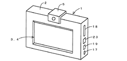
多用途一体型映像伝送装置1は、筐体(箱)2と、その中央部に矩形状に内蔵された液晶等からなる画像表示部3と、該画像表示部3と重なる形でその表面に形成された透明なタッチパネル4を備えている。また、その上部中央にカメラ5が着脱自在、かつその向きを前向きおよび後向きに変更自在に設置され、その右側側面に、例えば、PCMCIAインターフェース18,シリアルインターフェース23,イーサネットインターフェース19,およびUSBポート17等の端子が露出配置されている。前記タッチパネル4は、ポインティングデバイスの働きをし、人間の指による接触で、データや命令を本装置に入力することができる。
【0010】
図2は、該多用途一体型映像伝送装置1のハード構成を示すブロック図である。内部CPU11上では、画像圧縮伝送および受信画像復号のためのソフトウェアが動作している。該ソフトウェアはROMメモリ15に格納されており、該ソフトウェアの実行の結果や操作画面を表示するのに必要な手段として、メモリコントローラ12、RAMメモリ13、および画像表示デバイス14が設けられている。
【0011】
I/Oコントローラ16は、前記ROMメモリ15からソフトウェアプログラムを読みだしたり、USBポート17,PCMIAインターフェース18,イーサネットインターフェース19,オーディオ入出力デバイス20,シリアルコントローラ21,および画像入力コントローラ22といった入出力インターフェースとのデータのやり取りをするために実装されている。該シリアルコントローラ21には、シリアルインターフェース23とポインティングデバイス24が接続されていて、該シリアルコントローラ21と、シリアルインターフェース23およびポインティングデバイス24との間のデータの入出力が可能になっている。
【0012】
前記画像入力コントローラ22には、前記カメラ5に相当する画像入力デバイス25が接続されており、映像の入力を行うことができる。また、前記オーディオ入出力デバイス20には、マイクやヘッドホンを接続して、音声の入力や出力(再生)を行うことができる。
【0013】
さらに、前記USBポート17,PCMIAインターフェース18およびシリアルインターフェース23には、通信モデム,ISDNターミナルアダプタ,PHS,および携帯電話等を接続し、通信路とすることができる。また、イーサネットインターフェース19には、イーサネットケーブルを接続して、LANへと直接接続することができる。
【0014】
次に、前記した構成を有する多用途一体型映像伝送装置1の応用例あるいは用途例を、以下に説明する。なお、本装置1内蔵の画像圧縮符号化ソフトウェアは、その用途に応じた符号化パラメータの切替機能を有している。使用者は、この切替機能を用いて、タッチパネル4から符号化パラメータの変更が可能である。例えば、動きの大きな撮影対象を符号化する場合には、フレームスキップを長めに設定し、1フレーム毎への情報割当てを大きく取る。一方、動きの小さい画像を撮影する場合には、1フレームへの情報割当てを小さくし、かつ静止部分を符号化対象から除外(背景分離)する処理を行う。
【0015】
(1)車載テレビ電話装置
図3は、多用途一体型映像伝送装置1を車載テレビ電話装置に応用したときの概略斜視図を示す。装置本体1は、自動車内ダッシュボードあるいは座席シートなどにスタンド30、金具などを用いて固定される。通信手段としては、PCMIAインターフェース18に、PCMCIAモデムカード31を介して接続されたPHSや携帯電話機32、またはUSBポート17にコードにより接続されたPHSや携帯電話機32を用いることができる。該装置本体1および通信手段により、移動体通信が可能になる。
【0016】
本装置1の操作は、全て前記ポインティングデバイス24、すなわちタッチパネル4を用いて行うことができる。例えば、該ポインティングデバイス24を用いて、通信相手アドレスの指定、接続開始等の発呼操作、および終了操作等を行うことができる。ポインティングデバイス24から入力された電話番号および発呼のための信号は、画像表示デバイス14に表示されると共に、CPU11で解釈され、USBポート17、あるいはPCMCIAインターフェース18等に接続されたPHSや携帯電話機32を経て、図示されていないネットワークに出力される。
【0017】
送信側の映像は、本装置1に内蔵されている前記画像入力デバイス25(カメラ5)により取り込まれ、本装置1内部の前記画像圧縮伝送のためのソフトウェアにより圧縮符号化される。圧縮されたビットストリームは、通信インターフェースを経て、通信機器へと入力され、送信される。すなわち、送信側の映像は、図2の画像入力デバイス25→画像入力コントローラ22→I/Oコントローラ16→(メモリコントローラ12⇔ROMメモリ⇔CPU11⇔RAMメモリ)の経路により圧縮符号化され、I/Oコントローラ16→USBポート17を経て、PHSや携帯電話機32に出力される。さらに、映像信号は、該PHSや携帯電話機32のアンテナから、図示されていないネットワークへ出力される。
【0018】
一方、音声信号は、オーディオ入出力デバイス20から入力され、前記映像信号の場合と同様の経路により圧縮符号化され、PHSや携帯電話機32に出力される。さらに、該PHSや携帯電話機32のアンテナを経て、ネットワークへ出力される。
【0019】
着信があった場合は、待ち受け状態にあるCPU11が着信を検知し、所定の受信の処理をする。受信された画像/音声信号は、同じく通信インターフェースを経て、本装置1内部のソフトウェアにより取り込まれる。その後、該受信された画像/音声信号はCPU11等により復号され、画像信号は画像表示デバイス1に表示され、音声信号はオーディオ入出力デバイス20から出力される。
【0020】
(2)監視映像伝送装置
図4は、多用途一体型映像伝送装置1を監視映像伝送装置に応用したときの概略斜視図を示す。監視映像伝送装置として使用する場合は、まず、本装置を監視する地点に固定的に設置し、運用者が事前にポインティングデバイス24を使用して、本装置の初期設定をしておく。
【0021】
監視映像信号および/または音声信号は、前記車載テレビ電話装置の場合と同様にして、CPU11などで圧縮符号化され、PCMCIAインターフェース18に接続されたPCMCIAモデムカード31を介して電話ジャックに送られる。また、イーサネットインターフェース19に接続されたイーサネットLANに送出することができる。さらに、USBポート17に接続されたPHS、携帯電話などに、あるいは、該PHS、携帯電話などを介して図示されていないネットワークに送出することができる。
【0022】
また、侵入者検知装置等を別途用意し、該検知装置からのアラーム信号をシリアルインターフェース23を通して本装置1に入力し、該アラーム信号をトリガとして、本装置1が監視者に対して監視映像を送信開始するようにすることができる。勿論、初期設定時にセットするモードによっては、常に監視映像の送信を続けるといった動作も可能である。
【0023】
(3)前方映像伝送装置
図5は、多用途一体型映像伝送装置1を前方映像伝送装置に応用したときの概略斜視図を示す。本装置1を、図示されているように、例えば自動車のダッシュボードに設置し、カメラ5を前向きに設置すれば、運転中の自動車の前方の風景をカメラ5で撮影して伝送することができる。これは、本装置1に内蔵されている脱着可能カメラ5を筐体2から一旦引き抜き、180°回転させて筐体2のカメラ受けに差し込むことで実現することができる。
【0024】
この場合、前記画像表示部3とその表面に形成された透明なタッチパネル4とを室内方向に向けておけば、カメラ5が正常に前方の風景を映出しているかどうかを運転者などの乗員が確認したり、該タッチパネル4を用いて他の用途、例えば前記(1)の車載テレビ電話と併用したりすることができる。
【0025】
なお、カメラ5で映した映像の圧縮符号化等の処理および伝送は、前記(1)の車載テレビ電話と同様の方法で実施することができる。
【0026】
(4)可搬型映像伝送装置
図6は、多用途一体型映像伝送装置1を可搬型映像伝送装置に応用したときの概略斜視図を示す。この可搬型映像伝送装置は、本装置1のPCMCIAインターフェース18にPCMCIA PHSカード33を差込み、これにPHSや携帯電話を接続して、移動しながら撮影した映像を圧縮伝送するものである。
【0027】
通信機器としては、PCMCIA型のPHSカードが最も適しているが、(1)で使用したようなUSBポート17あるいはPCMCIAインターフェース18を介して、PHSや携帯電話機を接続するようにしてもよい。
【0028】
カメラ5は、筐体2から脱着かつ伸縮可能であり、筐体2から取り外して被写体の方向に自由に向けることにより、的確に被写体を捉えることができる。該可搬型映像伝送装置は、報道用映像伝送やテレビ電話などに使用することができる。
【0029】
この場合、カメラ5と本装置1とを結ぶケーブルの伸張の程度を測定する手段を本装置1に設置し、該ケーブルが所定長以上に伸張された時にCPU11に通知して、適切な圧縮符号化パラメータに、自動的に切り替えるようにすることが可能である。前記ケーブルの伸張の程度を測定する手段としては、例えば該ケーブルを巻回するプーリなどの回転回数を測定する手段や、ケーブルの所定長の所に付けられたマーカを検出する手段を用いることができ、検出結果はI/Oコントローラ16等を介してCPU11に通知することができる。また、圧縮符号化パラメータとしては、ケーブルが所定長以上に伸張されてカメラ5が使用される場合は、一般的にカメラ5を手に持って使用されることになるから、手ぶれをする画像、換言すれば背景が揺れる画像に適したものを選択する。逆に、ケーブルが所定長以上に伸張されないで使用されるときは、一般にカメラ5は本装置1に装着されて使用される場合であるから、カメラ5で映された画像の背景は静止している。したがって、背景が静止している画像を符号化するのに適した圧縮符号化パラメータが選択される。
【0030】
また、本装置1のカメラ5の装着部に、例えばマイクロスイッチを設けておき、カメラ5が装着された時にオン、取り外された時にオフになるようにすることにより、カメラ5の着脱状態をI/Oコントローラ16等を介してCPU11に通知することができる。また、カメラ5が前向きに装着されたらオン、後ろ向きに装着されたらオフになる例えばマイクロスイッチをさらに1個追加することにより、CPU11はカメラ5が前向きに装着されているか、後ろ向きに装着されているかを検知することができる。
【0031】
CPU11は、前記カメラ5の装着の有無、装着の方向により、圧縮符号化のパラメータを自動的に変えることができる。これにより、カメラの状態に応じて映される映像の性質、例えばカメラを装着して写される車内の映像等の動きが小さく背景が動かない映像、カメラを取り外して写される車外の映像等の動きが速く背景が動く映像等の性質に応じて、適切な圧縮符号化パラメータに、自動的に切り替えることが可能になる。
【0032】
(5)カメラ切替機能付き監視映像伝送装置
図7は、多用途一体型映像伝送装置1をカメラ切替機能付き監視映像伝送装置に応用したときの概略斜視図を示す。このカメラ切替機能付き監視映像伝送装置は、前記(2)の監視映像伝送装置に、複数の画像入力デバイス25、すなわちカメラ51〜54を追加したものである。図8は、図7の本体1のハード構成を示すブロック図である。該ブロック図では、I/Oコントローラ16に複数個の画像入力コントローラ22a〜22nが並列接続され、該複数個の画像入力コントローラ22a〜22nのそれぞれに、画像入力デバイス25a〜25nが接続される。なお、他の符号は図2と同一又は同等物を示す。
【0033】
複数のカメラ51〜54からの映像は、ROMメモリ15に格納され、CPU11などにより実行される、画像圧縮伝送ソフトウェアに取り込まれる。ここで、カメラ51〜54からの複数映像を、1画面の分割画面に割り当てて1つの映像信号としたり、選択したカメラからの映像を1つの映像信号としたりして、圧縮伝送をする。
【0034】
複数画像を分割画面映像として伝送するか、あるいはどのカメラの映像を選択的に伝送するするかについては、使用者が初期設定時に行うか、監視中に監視者がネットワークを通じて映像切替のためのコマンドを本装置1に送ることによって実現できる。
【0035】
以上、本発明の多用途一体型映像伝送装置の構成、用途例について説明したが、該説明に限定されず他の種々の用途にも応用することができることは明らかである。
【0036】
【発明の効果】
以上の説明から明らかなように、請求項1〜10の発明によれば、カメラで撮影した画像をリアルタイムで伝送でき、かつ利便性に優れた、パソコンをベースとする多用途の一体型映像伝送装置を提供することができる。また、カメラで撮影した画像を、画像表示部に表示でき、圧縮符号化でき、かつデータや命令をタッチパネルから手入力で入力できる、多機能でコンパクトに構成されたパソコンをベースとする多用途の一体型映像伝送装置を提供することができる。
【0037】
また、請求項1,2,4の発明によれば、カメラの状態に依存して伝送される可能性が高い画像の性質に応じて、適当な圧縮符号化のパラメータを自動的に設定することができるようになる。これにより、使用環境の変化に応じて、適切な画像圧縮符号化のパラメータを設定する作業が軽減されると共に、使用の際の利便性が向上する。
【0038】
また、請求項3、5の発明によれば、カメラが着脱自在、かつその向きを例えば180°変えて装着できるので、可搬型映像伝送装置や、自動車などに搭載して使用する前方映像伝送装置に用いると、利便性が大きい。
【0039】
また、請求項7の発明によれば、種々の入出力インターフェースを具備しているので、種々の外部機器に接続することができる。このため、使用目的に適合した外部機器を選択的に使用できるようになる。
【0040】
また、請求項9、10の発明によれば、発呼のための電話番号や命令をタッチパネルから手入力できるので、操作性の良い車載テレビ電話装置を提供することができる。
【図面の簡単な説明】
【図1】 本発明の多用途一体型映像伝送装置の一実施形態の外観斜視図である。
【図2】 該多用途一体型映像伝送装置のハード構成のブロック図である。
【図3】 用途例として、車載テレビ電話装置とした場合の外観斜視図である。
【図4】 用途例として、監視映像伝送装置とした場合の外観斜視図である。
【図5】 用途例として、前方映像伝送装置とした場合の外観斜視図である。
【図6】 用途例として、可搬型映像伝送装置とした場合の外観斜視図である。
【図7】 用途例として、カメラ切替機能付き監視映像伝送装置とした場合の外観斜視図である。
【図8】 該カメラ切替機能付き監視映像伝送装置のハード構成のブロック図である。
【符号の説明】
1・・・多用途一体型映像伝送装置、2・・・筐体、3・・・画像表示部、4・・・タッチパネル、5、51〜54・・・カメラ、11・・・CPU、12・・・メモリコントローラ、13・・・RAMメモリ、14・・・画像表示デバイス、15・・・ROMメモリ、16・・・I/Oコントローラ、17・・・USBポート、18・・・PCMCIAインターフェース、19・・・イーサネットインターフェース、20・・・オーディオ入出力デバイス、21・・・シリアルコントローラ、22、22a〜22n・・・画像入力コントローラ、23・・・シリアルインターフェース、24・・・ポインティングデバイス、25、25a〜25n・・・画像入力デバイス、32・・・携帯電話またはPHS。[0001]
BACKGROUND OF THE INVENTION
TECHNICAL FIELD The present invention relates to a versatile integrated video transmission device, and in particular, can be used in an in-vehicle videophone, a surveillance video transmission device, a front video transmission device, a portable video transmission device, a surveillance video transmission device with a camera switching function, and the like. The present invention relates to a versatile integrated video transmission apparatus.
[0002]
[Prior art]
2. Description of the Related Art Conventionally, it is known that an image input device such as a camera is attached to a notebook personal computer, and an image captured by the camera is taken as a file into a storage device of the notebook personal computer. In addition, a mobile phone in which a camera is fixedly attached to a part of a housing is known.
[0003]
[Problems to be solved by the invention]
However, in the above-described conventional apparatus, that is, a conventional apparatus based on a personal computer, an image captured by a camera is captured as a file in a storage device of the personal computer and cannot be transmitted in real time. For this reason, the personal computer cannot be used for a video phone, a surveillance video transmission device, a front video transmission device, a portable video transmission device, or the like.
[0004]
In addition, it is difficult to photograph a speaker or the like while talking on a mobile phone with a camera fixedly attached, and there is a problem in convenience and the like. Moreover, the use was only for mobile phones, and it could not be used for many purposes.
[0005]
The present invention has been made in view of the above-described prior art, and an object of the present invention is to provide a versatile integrated video transmission based on a personal computer that can transmit an image taken by a camera in real time and is excellent in convenience. To provide an apparatus.
[0006]
[Means for Solving the Problems]
To achieve the above object, the present invention provides an audio input / output device, an image input device, means for detecting whether or not the image input device is attached to the apparatus body, and the image input device. means for transmitting an image signal compression coding captured from an image display device for displaying an image signal captured from the image input device, is formed on the surface in the form of overlapping with the image display device, manually input , A transparent touch panel that allows you to enter data and commands ,
Means for detecting a degree of extension of a cable connecting the image input device and the apparatus main body ,
When the image input device is not attached to the apparatus main body, the degree of expansion of the cable connecting the image input device and the apparatus main body is detected, and the compression encoding parameter is changed according to the degree of expansion. It is characterized in that it can be done.
[0007]
This feature is based on a multi-function and compact personal computer that can display images taken with a camera on an image display device, compress and encode data, and manually input data and commands from a touch panel. Therefore, it is possible to provide a versatile integrated video transmission apparatus.
[0008]
DETAILED DESCRIPTION OF THE INVENTION
Hereinafter, the present invention will be described in detail with reference to the drawings. FIG. 1 is an external perspective view of a versatile integrated video transmission apparatus according to the present invention.
[0009]
The versatile integrated
[0010]
FIG. 2 is a block diagram showing a hardware configuration of the versatile integrated
[0011]
The I /
[0012]
An
[0013]
Further, a communication modem, ISDN terminal adapter, PHS, mobile phone, etc. can be connected to the
[0014]
Next, application examples or application examples of the multipurpose integrated
[0015]
(1) In-vehicle videophone device FIG. 3 is a schematic perspective view when the multipurpose integrated
[0016]
All operations of the
[0017]
The video on the transmission side is taken in by the image input device 25 (camera 5) built in the
[0018]
On the other hand, the audio signal is input from the audio input /
[0019]
When there is an incoming call, the CPU 11 in the standby state detects the incoming call and performs a predetermined reception process. The received image / sound signal is taken in by the software inside the
[0020]
(2) Surveillance Video Transmission Device FIG. 4 is a schematic perspective view when the multipurpose integrated
[0021]
The monitoring video signal and / or the audio signal are compressed and encoded by the CPU 11 or the like and sent to the telephone jack via the
[0022]
Also, an intruder detection device or the like is separately prepared, an alarm signal from the detection device is input to the
[0023]
(3) Front Video Transmission Device FIG. 5 is a schematic perspective view when the multipurpose integrated
[0024]
In this case, if the
[0025]
It should be noted that the processing and transmission such as compression encoding of the video imaged by the
[0026]
(4) Portable Video Transmission Device FIG. 6 is a schematic perspective view when the versatile integrated
[0027]
A PCMCIA type PHS card is most suitable as a communication device, but a PHS or a mobile phone may be connected via the
[0028]
The
[0029]
In this case, a means for measuring the degree of extension of the cable connecting the
[0030]
In addition, for example, a micro switch is provided in the mounting portion of the
[0031]
The CPU 11 can automatically change the compression encoding parameters depending on whether or not the
[0032]
(5) Surveillance Video Transmission Device with Camera Switching Function FIG. 7 is a schematic perspective view when the multipurpose integrated
[0033]
Videos from the plurality of cameras 51 to 54 are stored in the ROM memory 15 and taken into image compression / transmission software executed by the CPU 11 or the like. Here, a plurality of videos from the cameras 51 to 54 are allocated to one divided screen as one video signal, or a video from the selected camera is used as one video signal for compression transmission.
[0034]
Whether to transmit multiple images as split-screen video or to selectively transmit which video from the camera is performed by the user at the initial setting, or during monitoring, the monitor uses a command for video switching over the network. Can be realized by sending to the
[0035]
The configuration and application examples of the multipurpose integrated video transmission apparatus of the present invention have been described above. However, the present invention is not limited to the description and can be applied to various other applications.
[0036]
【The invention's effect】
As is apparent from the above description, according to the inventions of
[0037]
According to the first , second, and fourth aspects of the present invention, appropriate compression encoding parameters are automatically set according to the nature of an image that is highly likely to be transmitted depending on the camera state. Will be able to. This reduces the work of setting appropriate image compression encoding parameters in accordance with changes in the usage environment, and improves convenience in use.
[0038]
Further, according to the inventions of
[0039]
According to the seventh aspect of the present invention, since various input / output interfaces are provided, it can be connected to various external devices. For this reason, it becomes possible to selectively use an external device suitable for the purpose of use.
[0040]
Further, according to the ninth and tenth aspects of the invention, a telephone number and a command for making a call can be manually input from the touch panel, so that an in-vehicle videophone device with good operability can be provided.
[Brief description of the drawings]
FIG. 1 is an external perspective view of an embodiment of a versatile integrated video transmission apparatus according to the present invention.
FIG. 2 is a block diagram of a hardware configuration of the versatile integrated video transmission apparatus.
FIG. 3 is an external perspective view of an in-vehicle videophone device as an application example.
FIG. 4 is an external perspective view of a surveillance video transmission device as an application example.
FIG. 5 is an external perspective view of a front video transmission device as an application example.
FIG. 6 is an external perspective view of a portable video transmission device as an application example.
FIG. 7 is an external perspective view of a surveillance video transmission apparatus with a camera switching function as an application example.
FIG. 8 is a block diagram of a hardware configuration of the surveillance video transmission apparatus with a camera switching function.
[Explanation of symbols]
DESCRIPTION OF
Claims (10)
画像入力デバイスと、
該画像入力デバイスが該装置本体に装着状態にあるか否かを検出する手段と、
該画像入力デバイスから取り込んだ画像信号を圧縮符号化して伝送する手段と、
前記画像入力デバイスから取り込まれた画像信号を表示する画像表示デバイスと、
該画像表示デバイスと重なる形でその表面に形成され、手入力で、データや命令を入力することができるようにした透明なタッチパネルと、
該画像入力デバイスと前記装置本体とを結ぶケーブルの伸張の程度を検出する手段とを具備し、
前記画像入力デバイスが前記装置本体に非装着状態の時には、該画像入力デバイスと前記装置本体とを結ぶケーブルの伸張の程度を検出し、該伸張の程度によって前記圧縮符号化のパラメータを変えることのできる多用途一体型映像伝送装置。An audio input / output device;
An image input device;
Means for detecting whether or not the image input device is attached to the apparatus main body;
Means for compressing and transmitting an image signal captured from the image input device;
An image display device for displaying an image signal captured from the image input device;
A transparent touch panel that is formed on the surface of the image display device so as to overlap with the image display device and allows manual input of data and instructions ;
Means for detecting a degree of extension of a cable connecting the image input device and the apparatus main body ,
When the image input device is not attached to the apparatus main body, the degree of expansion of the cable connecting the image input device and the apparatus main body is detected, and the compression encoding parameter is changed according to the degree of expansion. versatile integrated video transmission apparatus.
前記画像表示デバイスに受信した画像信号を表示させ、前記タッチパネルから通信相手アドレスの入力、接続開始、および終了の操作を行うことができるようにしたことを特徴とする請求項1ないし7のいずれかに記載の多用途一体型映像伝送装置。Furthermore, it comprises an image signal receiver,
Wherein to display the received image signal to the image display device, the input of the communication destination address from the touch panel, connection initiation, and any one of claims 1 to 7, characterized in that to be able to operate the termination A versatile integrated video transmission device according to 1.
Priority Applications (1)
| Application Number | Priority Date | Filing Date | Title |
|---|---|---|---|
| JP2001330829A JP3873232B2 (en) | 2001-10-29 | 2001-10-29 | Multi-use integrated video transmission device |
Applications Claiming Priority (1)
| Application Number | Priority Date | Filing Date | Title |
|---|---|---|---|
| JP2001330829A JP3873232B2 (en) | 2001-10-29 | 2001-10-29 | Multi-use integrated video transmission device |
Publications (2)
| Publication Number | Publication Date |
|---|---|
| JP2003134486A JP2003134486A (en) | 2003-05-09 |
| JP3873232B2 true JP3873232B2 (en) | 2007-01-24 |
Family
ID=19146498
Family Applications (1)
| Application Number | Title | Priority Date | Filing Date |
|---|---|---|---|
| JP2001330829A Expired - Fee Related JP3873232B2 (en) | 2001-10-29 | 2001-10-29 | Multi-use integrated video transmission device |
Country Status (1)
| Country | Link |
|---|---|
| JP (1) | JP3873232B2 (en) |
Families Citing this family (12)
| Publication number | Priority date | Publication date | Assignee | Title |
|---|---|---|---|---|
| EP1544834A3 (en) * | 2003-12-17 | 2006-12-20 | KJ GmbH Installationen | Display panel and method for displaying |
| KR20050065880A (en) * | 2003-12-26 | 2005-06-30 | 재단법인 포항산업과학연구원 | Programmable logic controller for wire/wireless communication by using embedded linux |
| KR20060130204A (en) * | 2004-02-06 | 2006-12-18 | 소프트뱅크비비 가부시키가이샤 | Videophone system, self-support base station device, set top box, and videophone method |
| JP4453579B2 (en) * | 2005-03-10 | 2010-04-21 | トヨタ自動車株式会社 | Car phone system |
| GB2431904A (en) * | 2005-06-29 | 2007-05-09 | Stuart Feasby | Camera and display screen device for a vehicle |
| JP2007208888A (en) * | 2006-02-06 | 2007-08-16 | Seru Corporation:Kk | Moving image distribution system |
| EP2581267A1 (en) * | 2011-10-10 | 2013-04-17 | Robert Bosch GmbH | Driving assistance device |
| CN105869426A (en) * | 2016-06-06 | 2016-08-17 | 合肥天地软件科技有限公司 | Dustproof structure of bus electronic station board |
| CN109587386A (en) * | 2019-01-21 | 2019-04-05 | 甘肃佳沃信息科技有限公司 | A kind of portable recording camera |
| JP7446612B2 (en) * | 2019-03-19 | 2024-03-11 | 株式会社ユピテル | In-vehicle equipment |
| JP2021005401A (en) * | 2020-09-15 | 2021-01-14 | 株式会社ユピテル | On-vehicle instrument |
| JP2021005402A (en) * | 2020-09-15 | 2021-01-14 | 株式会社ユピテル | On-vehicle instrument |
Family Cites Families (18)
| Publication number | Priority date | Publication date | Assignee | Title |
|---|---|---|---|---|
| JP3172199B2 (en) * | 1990-04-04 | 2001-06-04 | 株式会社東芝 | Videophone equipment |
| JPH0453340A (en) * | 1990-06-20 | 1992-02-20 | Mitsubishi Electric Corp | Video telephone set |
| JPH0575988A (en) * | 1991-02-08 | 1993-03-26 | Canon Inc | Communication device |
| JPH05276397A (en) * | 1992-03-25 | 1993-10-22 | Toshiba Corp | Picture transmission equipment |
| JPH0670314A (en) * | 1992-08-21 | 1994-03-11 | Canon Inc | Picture processor |
| JPH06121220A (en) * | 1992-10-08 | 1994-04-28 | Mitsubishi Electric Corp | Integral type image pickup and receiving device |
| JP3613741B2 (en) * | 1995-07-10 | 2005-01-26 | コニカミノルタホールディングス株式会社 | Digital still camera and video conference system |
| JPH1075287A (en) * | 1996-08-30 | 1998-03-17 | Kokusai Electric Co Ltd | Portable video telephone |
| JPH10173827A (en) * | 1996-12-06 | 1998-06-26 | Aqueous Res:Kk | Image data communication system |
| JPH10173983A (en) * | 1996-12-06 | 1998-06-26 | Canon Inc | Image pickup device, image processor and image pickup system |
| JP3655734B2 (en) * | 1997-06-04 | 2005-06-02 | ペンタックス株式会社 | Image compression apparatus and image display apparatus |
| JPH11187295A (en) * | 1997-12-24 | 1999-07-09 | Canon Inc | Portable videophone and voice collection method |
| JP2000152069A (en) * | 1998-11-09 | 2000-05-30 | Toshiba Corp | Photographing device, video transmission system, video receiver, video transmitter, video encoding device, and video reproducing device |
| JP2001024921A (en) * | 1999-07-05 | 2001-01-26 | Ricoh Co Ltd | Portable electronic equipment |
| JP2001128131A (en) * | 1999-10-28 | 2001-05-11 | Casio Comput Co Ltd | Picture communication system, communication terminal equipment and recording medium |
| JP2001145073A (en) * | 1999-11-11 | 2001-05-25 | Korabotekku:Kk | Moving picture transmission method |
| JP3546784B2 (en) * | 1999-12-14 | 2004-07-28 | 日本電気株式会社 | Mobile device |
| JP2001230954A (en) * | 2000-02-15 | 2001-08-24 | Fuji Photo Film Co Ltd | Image pickup device |
-
2001
- 2001-10-29 JP JP2001330829A patent/JP3873232B2/en not_active Expired - Fee Related
Also Published As
| Publication number | Publication date |
|---|---|
| JP2003134486A (en) | 2003-05-09 |
Similar Documents
| Publication | Publication Date | Title |
|---|---|---|
| JP3873232B2 (en) | Multi-use integrated video transmission device | |
| JP4443181B2 (en) | Communication system and method | |
| KR101450580B1 (en) | Method and Apparatus for composing images | |
| KR100678226B1 (en) | Method for operating in mobile phone having detachable wireless display window | |
| JP3658036B2 (en) | Image input system and method for controlling image input system | |
| KR100703332B1 (en) | Method for changing operation mode in wireless terminal | |
| KR100678209B1 (en) | Method for controlling image in wireless terminal | |
| EP2364000A1 (en) | Method for controlling a camera mode in a portalble terminal | |
| CN111050062B (en) | Shooting method and electronic equipment | |
| KR20040089889A (en) | Method for using rotation key apparatus in wireless terminal | |
| KR20070012059A (en) | Method for displaying emotion in video telephone mode of wireless terminal | |
| KR100646031B1 (en) | Method and mobile telecommunication terminal for controlling input by using the movement of pupil | |
| US20060274039A1 (en) | Method of performing communication in a wireless terminal and wireless terminal implementing the same | |
| KR100703462B1 (en) | Method for changing image attach mode in wireless terminal | |
| KR100678130B1 (en) | Method for performing call in wireless terminal | |
| JP2005130339A (en) | Cellular phone system, data transmission method, and data transmission system | |
| KR100678208B1 (en) | Method for saving and displaying image in wireless terminal | |
| KR100606079B1 (en) | Method for zooming of picture in wireless terminal | |
| KR100557096B1 (en) | Method for displaying data in wireless terminal with both camera | |
| KR100678261B1 (en) | Method for performing multitasking in wireless terminal | |
| JP2001345895A (en) | Portable telephone set | |
| JP4508998B2 (en) | Remote camera control device | |
| WO2007072583A1 (en) | Device for displaying taken image and method of displaying taken image | |
| KR100664154B1 (en) | Method for displaying of picture move in wireless terminal | |
| KR100713438B1 (en) | Method for calling between wireless terminal and headset |
Legal Events
| Date | Code | Title | Description |
|---|---|---|---|
| A621 | Written request for application examination |
Free format text: JAPANESE INTERMEDIATE CODE: A621 Effective date: 20041007 |
|
| A131 | Notification of reasons for refusal |
Free format text: JAPANESE INTERMEDIATE CODE: A131 Effective date: 20060719 |
|
| A521 | Request for written amendment filed |
Free format text: JAPANESE INTERMEDIATE CODE: A523 Effective date: 20060915 |
|
| TRDD | Decision of grant or rejection written | ||
| A01 | Written decision to grant a patent or to grant a registration (utility model) |
Free format text: JAPANESE INTERMEDIATE CODE: A01 Effective date: 20061011 |
|
| A61 | First payment of annual fees (during grant procedure) |
Free format text: JAPANESE INTERMEDIATE CODE: A61 Effective date: 20061012 |
|
| R150 | Certificate of patent or registration of utility model |
Free format text: JAPANESE INTERMEDIATE CODE: R150 |
|
| FPAY | Renewal fee payment (event date is renewal date of database) |
Free format text: PAYMENT UNTIL: 20101102 Year of fee payment: 4 |
|
| FPAY | Renewal fee payment (event date is renewal date of database) |
Free format text: PAYMENT UNTIL: 20111102 Year of fee payment: 5 |
|
| FPAY | Renewal fee payment (event date is renewal date of database) |
Free format text: PAYMENT UNTIL: 20111102 Year of fee payment: 5 |
|
| FPAY | Renewal fee payment (event date is renewal date of database) |
Free format text: PAYMENT UNTIL: 20111102 Year of fee payment: 5 |
|
| FPAY | Renewal fee payment (event date is renewal date of database) |
Free format text: PAYMENT UNTIL: 20111102 Year of fee payment: 5 |
|
| FPAY | Renewal fee payment (event date is renewal date of database) |
Free format text: PAYMENT UNTIL: 20121102 Year of fee payment: 6 |
|
| FPAY | Renewal fee payment (event date is renewal date of database) |
Free format text: PAYMENT UNTIL: 20121102 Year of fee payment: 6 |
|
| FPAY | Renewal fee payment (event date is renewal date of database) |
Free format text: PAYMENT UNTIL: 20131102 Year of fee payment: 7 |
|
| R250 | Receipt of annual fees |
Free format text: JAPANESE INTERMEDIATE CODE: R250 |
|
| R250 | Receipt of annual fees |
Free format text: JAPANESE INTERMEDIATE CODE: R250 |
|
| S533 | Written request for registration of change of name |
Free format text: JAPANESE INTERMEDIATE CODE: R313533 |
|
| R350 | Written notification of registration of transfer |
Free format text: JAPANESE INTERMEDIATE CODE: R350 |
|
| LAPS | Cancellation because of no payment of annual fees |