JP3870552B2 - Brake device - Google Patents
Brake device Download PDFInfo
- Publication number
- JP3870552B2 JP3870552B2 JP14675698A JP14675698A JP3870552B2 JP 3870552 B2 JP3870552 B2 JP 3870552B2 JP 14675698 A JP14675698 A JP 14675698A JP 14675698 A JP14675698 A JP 14675698A JP 3870552 B2 JP3870552 B2 JP 3870552B2
- Authority
- JP
- Japan
- Prior art keywords
- lever
- release
- operation lever
- brake device
- ratchet
- Prior art date
- Legal status (The legal status is an assumption and is not a legal conclusion. Google has not performed a legal analysis and makes no representation as to the accuracy of the status listed.)
- Expired - Fee Related
Links
- 230000002093 peripheral effect Effects 0.000 claims description 6
- 230000013011 mating Effects 0.000 claims 1
- 230000005540 biological transmission Effects 0.000 description 3
- 210000000078 claw Anatomy 0.000 description 3
- 238000004904 shortening Methods 0.000 description 2
- 230000000694 effects Effects 0.000 description 1
- 230000002452 interceptive effect Effects 0.000 description 1
- 230000007257 malfunction Effects 0.000 description 1
- 239000011347 resin Substances 0.000 description 1
- 229920005989 resin Polymers 0.000 description 1
Images


Landscapes
- Braking Elements And Transmission Devices (AREA)
- Mechanical Control Devices (AREA)
Description
【0001】
【発明の属する技術分野】
本発明は、操作レバーを手動操作してブレーキの解除を行うブレーキ装置に関する。
【0002】
【従来の技術】
操作レバーを手動操作してブレーキの解除を行うセンターレバー方式のブレーキ装置では、操作レバーの端部に進退可能に設けられた解除ボタンが設けられていて、この解除ボタンを操作レバーの内部に向かって押すことで、レリーズロッドを移動してラチェット爪をラチェットプレート歯から離脱するように構成されている。
【0003】
【発明が解決しようとする課題】
従来のブレーキ装置を有する車両では、変速装置の変速レバーとブレーキ装置の操作レバーとが近接する場合がある。このような配置であると、操作レバーの端部側に充分なスペースを確保できない場合がある。このため、ブレーキ解除操作を行うと、解除ボタンを操作する指が変速レバーや変速レバーの基端側を覆うコラムカバーと干渉して操作性の観点で好ましくない。操作レバーを短くすることも一案ではあるが、ブレーキ装置の制動力は、操作レバーのレバー長と比例関係となるように設定されているので、レバー長は制動力の観点から見ても短縮しない方が望ましい。レバー長が短くなると、レバー長が長いものと同一の制動力を得ようとしたときに、テコの原理により大きな操作力が必要となる。この状態は、操作性の点で好ましくない。本発明は、操作レバーの長さを確保して充分な制動力を得ながら、省スペースで操作性のよいブレーキ装置を提供することを目的とする。
【0004】
【課題を解決するための手段】
本発明は、上記目的を達成するため、ラチェットプレート歯と、これに係脱可能に設けられたラチェット爪との係合により、車体側にその基部を枢支された操作レバーを任意の位置に保持するブレーキ装置において、操作レバーの端部に装着固定され、その内部空間から外周面まで連通する傾斜溝が形成されたグリップ部と、傾斜溝に挿入され、その先端を上記グリップ部の外周面から突出させて移動可能な解除レバーと、一端が上記ラチェット爪に連結され、他端が上記解除レバーの基端に結合されていて、上記解除レバーの移動動作を上記ラチェット爪に伝達し、上記ラチェットプレート歯との係合位置と非係合位置とに上記ラチェット爪を変位させるレリーズロッドとを備えたことを特徴としている。
【0005】
このように構成すると、操作レバーの長さを短くすることなく、また、操作レバーの操作時における操作者の指と変速レバーやコラムカバーとの干渉がなくなり、ブレーキ装置の操作性を向上することができる。
グリップ部の外観形状には、円形、多角形が挙げられるが、グリップ感や操作レバーの回動動作時の操作性を考慮すると楕円形が望ましい。
【0006】
【発明の実施の形態】
以下、本発明の実施の形態について図面を用いて詳細に説明する。
図1は、車両に用いるセンターレバー方式の駐車ブレーキ装置である。このブレーキ装置は、操作レバー3を備えている。操作レバー3は、その基部3aが車体側となるフロア1に図示しないボルトで固着されたブラケット2に、軸4を介して回動自在に支持されている。ブラケット2の一部には、連続した歯部をもつラチェットプレート歯5が円弧状に形成されている。ラチェットプレート歯5には、操作レバー3に支軸23で回動自在に装着されたラチェット爪6の下端6bが、離脱可能に噛合されている。
【0007】
操作レバー3は、図1に実線で示す制動解除位置と2点鎖線で示す制動位置とに変位可能となっている。軸4には、アーム8が固定されている。アーム8には、図示しない制動部にその一端が連結されるコントロールケーブル7の他端がピン結合されている。コントロールケーブル7は、操作レバー3を制動位置に位置させることで、図示しない車両に制動力を与えるようになっている。操作レバー3は、その表面を樹脂製の外被3Aで覆われている。
【0008】
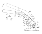
この形態は、図2、図3に示すように、グリップ部90に、グリップ部90の一部となる解除レバー122を設け、このレバーを操作することでブレーキ装置を解除できるようにしたものである。
【0009】
操作レバー3の端部3bには、インナーパイプ120が外被3Aと一体的設けられている。インナーパイプ120の外周には、有底筒状のグリップ部90の底部が先端90a側と成るように装着固定されている。この先端90aには、貫通孔17を介してグリップ部90の内部空間90cに連通する開口160が形成されている。グリップ部90には、先端90aから基端90bに向かって右下がりとなる傾斜溝144が形成されている。この傾斜溝144は、グリップ90の外周面90dから内部空間90cまで連通している。傾斜溝144の長さは、下端6bとラチェットプレート歯5との係合が解除でき得る程度、レリーズロッド11を移動できる寸法となっている。グリップ部90の外形は、楕円形に形成されている。
【0010】
レリーズロッド11は、図3に示すように、インナーパイプ120の内部を通り、その他端11bを連通孔17にワッシャ19を介して回動可能に挿通されている。他端11bの先端の一部には、ねじ部180が形成されている。他端11bの最先端は、開口160内に位置してストッパリング123が装着されている。 ねじ部180には、解除レバー122の基端122aが螺合されている。解除レバー122は、傾斜溝144に挿入され、その先端122bを外周面90dから突出させている。解除レバー122は、引っ張りバネ13による付勢力のかかるレリーズロッド11によってロック方向A2への移動習性を与えられており、通常、先端90a寄りに位置する傾斜溝144の端部側に配置されている。解除レバー122は、この位置をホームポジションとしている。
【0011】
このような構成のブレーキ装置の動作を説明するが、制動動作については第1の形態と同様であるので省略し、解除動作についてのみ説明する。図1に示す制動位置から制動解除位置へと操作レバー3を戻すには、解除レバー122を矢印C方向に押し回す。すると、操作レバー122が傾斜溝144に案内されてロック解除方向A1に回転移動してレリーズロッド11が同方向に押される。このため、図1に示すラチェット爪6が引っ張りバ ネ13の付勢力に抗して時計回り方向に回転して非係合位置を占め、下端6bとラチェットプレート歯5との噛み込みが解除される。グリップ部90が移動すると、ストッパリング123が開口160の底部160a内に当接して操作レバー122の移動が規制される。
【0012】
乗員は、解除レバー122を押した状態で、操作レバー3を制動解除位置まで押し下げる。これにより下端6bがラチェットプレート歯5から外れた領域に位置される。乗員がグリップ部90から手を離すと、レリーズロッド11が引っ張りバネ13の付勢力によってロック方向A2に移動する。解除レバー122は、レリーズロッド11の移動によって傾斜溝144に案内されてロック方向A2に回転移動されてホームポジションに戻される。
【0013】
このように、操作レバー3に装着したグリップ部90の解除レバー122を移動させることで、下端6bとラチェットプレート歯5との係合状態を解除できるので、従来のブレーキ装置のように、乗員の指がグリップ部90の先端90aから突出しなくなる。このため、操作レバー90を短くしなくても変速レバーやコラムカバーと指との干渉がなくなり、レバー長を確保しながら操作性を向上できる。
【0014】
操作レバー3を運転席と助手席の間に配置する場合、解除レバー122のホームポジションは、グリップ部90の側方に位置するように傾斜溝144の位置を設定し、運転席や助手席のシート上面から突出しないようにグリップ部90に設ける。このように設けると、シート上面側へ解除レバー122が突出しなくなるため、同レバーと、車室内の物や乗員との不用意な接触による誤作動を防止できると共に、運転席と助手席にまたがるように乗員が休息する場合でも邪魔にならない。
【0015】
【発明の効果】
本発明によれば、操作レバーの長さを短縮しなくても同レバーの操作時における操作者の指と変速レバーやコラムカバーとの干渉を防止できるので、操作レバーの長さを確保して充分な制動力を得ながら省スペース化を図れ、同時に操作性を向上することができる。
【図面の簡単な説明】
【図1】 本発明のブレーキ装置の概略構成を示す正面図である。
【図2】 本発明の要部となる操作レバーとグリップ部の構成を示す拡大斜視図である。
【図3】 図2に示す操作レバーとグリップ部の構成と動作を示す拡大断面図である。
【符号の説明】
1 車体側
3 操作レバー
3a 基部
3b 端部
5 ラチェットプレート歯
6 ラチェット爪
11 レリーズロッド
11a 一端
11b 他端
90 グリップ部
122 解除レバー
144 傾斜溝 [0001]
BACKGROUND OF THE INVENTION
The present invention relates to a brake device that manually operates an operation lever to release a brake.
[0002]
[Prior art]
In the center lever type brake device that releases the brake by manually operating the operation lever, a release button is provided at the end of the operation lever so as to be able to advance and retract, and this release button is directed toward the inside of the operation lever. By pushing and pushing, the release rod is moved to disengage the ratchet pawl from the ratchet plate teeth.
[0003]
[Problems to be solved by the invention]
In a vehicle having a conventional brake device, the transmission lever of the transmission device and the operation lever of the brake device may be close to each other. With such an arrangement, there may be a case where a sufficient space cannot be secured on the end side of the operation lever. For this reason, when the brake release operation is performed, the finger operating the release button interferes with the shift lever or the column cover covering the base end side of the shift lever, which is not preferable from the viewpoint of operability. Although shortening the operating lever is one idea, the braking force of the brake device is set to be proportional to the lever length of the operating lever, so the lever length is shortened from the standpoint of braking force. It is better not to. When the lever length is shortened, a large operating force is required due to the lever principle when trying to obtain the same braking force as that of the lever having a long lever length. This state is not preferable in terms of operability. An object of the present invention is to provide a space-saving and easy-to-operate brake device while securing a sufficient length of an operation lever to obtain a sufficient braking force.
[0004]
[Means for Solving the Problems]
In order to achieve the above-mentioned object, the present invention provides an operation lever pivotally supported on the vehicle body side at an arbitrary position by engagement of a ratchet plate tooth and a ratchet claw that is detachably attached to the tooth. In the holding brake device, a grip portion that is attached and fixed to the end portion of the operation lever and has an inclined groove that communicates from its inner space to the outer peripheral surface, and is inserted into the inclined groove, the tip of which is the outer peripheral surface of the grip portion A release lever that can be moved by protruding from the ratchet pawl, one end connected to the ratchet pawl, and the other end coupled to the base end of the release lever, to transmit the movement of the release lever to the ratchet pawl, A release rod for displacing the ratchet pawl is provided at the engagement position and the non-engagement position with the ratchet plate teeth.
[0005]
With this configuration, the length of the operation lever is not shortened, and there is no interference between the operator's finger and the speed change lever or the column cover when operating the operation lever, thereby improving the operability of the brake device. Can do.
The external shape of the grip portion may be a circle or a polygon, but an elliptical shape is desirable in consideration of the grip feeling and the operability when the operation lever is rotated.
[0006]
DETAILED DESCRIPTION OF THE INVENTION
It will be described in detail with reference to the drawings with the embodiment of the present invention.
FIG. 1 shows a center lever parking brake device used in a vehicle. This brake device includes an
[0007]
The
[0008]
In this embodiment, as shown in FIGS. 2 and 3, a release lever 122 which is a part of the
[0009]
An
[0010]
As shown in FIG. 3, the release rod 11 passes through the
[0011]
The operation of the brake device having such a configuration will be described. Since the braking operation is the same as that in the first embodiment, it will be omitted and only the releasing operation will be described. To return the
[0012]
The occupant pushes down the
[0013]
Thus, by moving the release lever 122 of the
[0014]
When the
[0015]
【The invention's effect】
According to the present invention, it is possible to prevent the operator's finger from interfering with the speed change lever and the column cover when operating the lever without shortening the length of the operation lever. Space can be saved while obtaining a sufficient braking force, and operability can be improved at the same time.
[Brief description of the drawings]
FIG. 1 is a front view showing a schematic configuration of a brake device of the present invention.
FIG. 2 is an enlarged perspective view showing a configuration of an operation lever and a grip part which are main parts of the present invention.
3 is an enlarged cross-sectional view showing the configuration and operation of an operation lever and a grip part shown in FIG. 2. FIG.
[Explanation of symbols]
DESCRIPTION OF SYMBOLS 1
11a one end
11b The other end
90 grip part 122 release lever
144 Inclined groove
Claims (1)
上記操作レバーの端部に装着固定され、その内部空間から外周面まで連通する傾斜溝が形成されたグリップ部と、
上記傾斜溝に挿入され、その先端を上記グリップ部の外周面から突出させて移動可能な解除レバーと、
一端が上記ラチェット爪に連結され、他端が上記解除レバーの基端に結合されていて、上記解除レバーの移動動作を上記ラチェット爪に伝達し、上記ラチェットプレート歯との係合位置と非係合位置とに上記ラチェット爪を変位させるレリーズロッドとを備えたことを特徴とするブレーキ装置。In the brake device for holding the operation lever pivotally supported on the vehicle body side at an arbitrary position by engagement of the ratchet plate tooth and the ratchet pawl provided detachably thereto,
A grip portion that is mounted and fixed to the end portion of the operation lever and has an inclined groove that communicates from the inner space to the outer peripheral surface;
A release lever that is inserted into the inclined groove and is movable with its tip protruding from the outer peripheral surface of the grip portion;
One end is connected to the ratchet pawl, and the other end is coupled to the base end of the release lever. The movement of the release lever is transmitted to the ratchet pawl, and the engagement position with the ratchet plate teeth is not engaged. A brake device comprising: a release rod for displacing the ratchet pawl at a mating position.
Priority Applications (1)
| Application Number | Priority Date | Filing Date | Title |
|---|---|---|---|
| JP14675698A JP3870552B2 (en) | 1998-05-28 | 1998-05-28 | Brake device |
Applications Claiming Priority (1)
| Application Number | Priority Date | Filing Date | Title |
|---|---|---|---|
| JP14675698A JP3870552B2 (en) | 1998-05-28 | 1998-05-28 | Brake device |
Publications (2)
| Publication Number | Publication Date |
|---|---|
| JPH11334549A JPH11334549A (en) | 1999-12-07 |
| JP3870552B2 true JP3870552B2 (en) | 2007-01-17 |
Family
ID=15414873
Family Applications (1)
| Application Number | Title | Priority Date | Filing Date |
|---|---|---|---|
| JP14675698A Expired - Fee Related JP3870552B2 (en) | 1998-05-28 | 1998-05-28 | Brake device |
Country Status (1)
| Country | Link |
|---|---|
| JP (1) | JP3870552B2 (en) |
Families Citing this family (2)
| Publication number | Priority date | Publication date | Assignee | Title |
|---|---|---|---|---|
| US6488130B1 (en) * | 2001-05-10 | 2002-12-03 | John Karl Bermel | Twist-grip brake for a cargo portage device |
| KR100925924B1 (en) | 2007-12-14 | 2009-11-09 | 현대자동차주식회사 | Parking brake lever structure of car |
-
1998
- 1998-05-28 JP JP14675698A patent/JP3870552B2/en not_active Expired - Fee Related
Also Published As
| Publication number | Publication date |
|---|---|
| JPH11334549A (en) | 1999-12-07 |
Similar Documents
| Publication | Publication Date | Title |
|---|---|---|
| KR100298053B1 (en) | Brake pedal apparatus for automotive vehicle | |
| JPS641349B2 (en) | ||
| JP3870552B2 (en) | Brake device | |
| JP4844063B2 (en) | Foot-operated parking brake device for vehicles | |
| KR100456515B1 (en) | Devide for automatically folding an automotive armrest | |
| JP3993975B2 (en) | Shift lever device | |
| KR100380437B1 (en) | The locking device of an automotive parking brake | |
| JPH0710979Y2 (en) | Foot-operated parking brake system for automobiles | |
| JPH10287217A (en) | Foot-operated parking brake device | |
| KR0154685B1 (en) | Foot brake for parking | |
| JP3660722B2 (en) | Shift lock device for column AT shift lever | |
| KR0178649B1 (en) | Pedal-type operation device of parking brake | |
| KR100643950B1 (en) | Car Mechanism for Parking Brake System | |
| KR100246678B1 (en) | Pedal parking brake | |
| JP3359549B2 (en) | Locking device for shift lever of automatic transmission | |
| JPH0522432Y2 (en) | ||
| JPH0810051Y2 (en) | Foot-operated parking brake release mechanism | |
| JP2632013B2 (en) | Stick type parking brake operating device | |
| JPH0744847Y2 (en) | Shift lock device for vehicle | |
| JP2571723B2 (en) | Steering lock device | |
| GB2291164A (en) | Parking brake operating mechanism | |
| JPH04283133A (en) | Shift lock release device of automatic transmission | |
| KR19980054860U (en) | Parking brake lever | |
| JPH0523227B2 (en) | ||
| KR19980037116U (en) | Sliding handbrake |
Legal Events
| Date | Code | Title | Description |
|---|---|---|---|
| A977 | Report on retrieval |
Free format text: JAPANESE INTERMEDIATE CODE: A971007 Effective date: 20040507 |
|
| A131 | Notification of reasons for refusal |
Free format text: JAPANESE INTERMEDIATE CODE: A131 Effective date: 20040525 |
|
| A711 | Notification of change in applicant |
Free format text: JAPANESE INTERMEDIATE CODE: A712 Effective date: 20040616 |
|
| A521 | Written amendment |
Free format text: JAPANESE INTERMEDIATE CODE: A523 Effective date: 20040709 |
|
| RD03 | Notification of appointment of power of attorney |
Free format text: JAPANESE INTERMEDIATE CODE: A7423 Effective date: 20040716 |
|
| A02 | Decision of refusal |
Free format text: JAPANESE INTERMEDIATE CODE: A02 Effective date: 20050329 |
|
| A521 | Written amendment |
Free format text: JAPANESE INTERMEDIATE CODE: A523 Effective date: 20050428 |
|
| A911 | Transfer of reconsideration by examiner before appeal (zenchi) |
Free format text: JAPANESE INTERMEDIATE CODE: A911 Effective date: 20050512 |
|
| A711 | Notification of change in applicant |
Free format text: JAPANESE INTERMEDIATE CODE: A712 Effective date: 20060426 |
|
| A131 | Notification of reasons for refusal |
Free format text: JAPANESE INTERMEDIATE CODE: A131 Effective date: 20060725 |
|
| A521 | Written amendment |
Free format text: JAPANESE INTERMEDIATE CODE: A523 Effective date: 20060831 |
|
| TRDD | Decision of grant or rejection written | ||
| A01 | Written decision to grant a patent or to grant a registration (utility model) |
Free format text: JAPANESE INTERMEDIATE CODE: A01 Effective date: 20060926 |
|
| A61 | First payment of annual fees (during grant procedure) |
Free format text: JAPANESE INTERMEDIATE CODE: A61 Effective date: 20061009 |
|
| R150 | Certificate of patent or registration of utility model |
Free format text: JAPANESE INTERMEDIATE CODE: R150 |
|
| S531 | Written request for registration of change of domicile |
Free format text: JAPANESE INTERMEDIATE CODE: R313531 |
|
| R350 | Written notification of registration of transfer |
Free format text: JAPANESE INTERMEDIATE CODE: R350 |
|
| LAPS | Cancellation because of no payment of annual fees |