JP3868600B2 - Method of folding gas bag and folding device - Google Patents
Method of folding gas bag and folding device Download PDFInfo
- Publication number
- JP3868600B2 JP3868600B2 JP29467997A JP29467997A JP3868600B2 JP 3868600 B2 JP3868600 B2 JP 3868600B2 JP 29467997 A JP29467997 A JP 29467997A JP 29467997 A JP29467997 A JP 29467997A JP 3868600 B2 JP3868600 B2 JP 3868600B2
- Authority
- JP
- Japan
- Prior art keywords
- gas bag
- folding
- folded
- wall
- base
- Prior art date
- Legal status (The legal status is an assumption and is not a legal conclusion. Google has not performed a legal analysis and makes no representation as to the accuracy of the status listed.)
- Expired - Fee Related
Links
Images


Classifications
-
- B—PERFORMING OPERATIONS; TRANSPORTING
- B60—VEHICLES IN GENERAL
- B60R—VEHICLES, VEHICLE FITTINGS, OR VEHICLE PARTS, NOT OTHERWISE PROVIDED FOR
- B60R21/00—Arrangements or fittings on vehicles for protecting or preventing injuries to occupants or pedestrians in case of accidents or other traffic risks
- B60R21/02—Occupant safety arrangements or fittings, e.g. crash pads
- B60R21/16—Inflatable occupant restraints or confinements designed to inflate upon impact or impending impact, e.g. air bags
- B60R21/23—Inflatable members
- B60R21/237—Inflatable members characterised by the way they are folded
- B60R2021/2375—Folding devices
Description
【0001】
【発明の属する技術分野】
本発明は自動車乗員拘束装置のガスバッグを折り畳む方法、自動車乗員拘束装置の折り畳まれたガスバッグ、および、本方法を実行するための装置に関する。自動車乗員拘束装置は通常、圧縮ガス源と、ガス源に対する引き金装置と、圧縮ガス源と連通し、圧縮ガス源が点火されたとき、容積縮小の折り畳まれた状態から、自動車乗員に拘束効果を及ぼす展開状態へと変化するガスバッグとから成る。
【0002】
【発明が解決しようとする課題】
この種のガスバッグ折り畳みには、いくつかの要求がある。第1に、ガスバッグを折り畳み状態から展開状態へ出来るだけ迅速に遷移させることである。さらに、折り畳みが自動的に行われ得ることが好ましい。これは自動車乗員拘束装置の製造コストを減少させる。
【0003】
【課題を解決するための手段】
本発明は、第1に、手動でなく自動的に実行され、第2に、折り畳まれたガスバッグを特に有利な態様で展開させるガスバッグ折り畳み方法を提供する。本発明の方法は下記の段階を有する。第1に、ガスバッグを基部上に拡げる。ついで、ガスバッグの膨脹開口の縁を固定する。つぎに、板を基部に平行に、基部から距離を置いて配置し、基部と板との間にガスバッグを置く。その後、ガスバッグが基部と板との間で展開するように、ガスバッグ内部に圧力を加える。最後に、ガスバッグの壁を、周縁に分布された数個の場所において内方へ押し付ける。かくて、非常に緊密に折り畳まれ、しかも、展開容易なガスバッグが得られる。従来の折り畳み方法に比較して、ガスバッグの展開所要時間の改善が見られる。さらに、ガスバッグの一層均一な展開と、折り畳まれたガスバッグを保護するカバーの改善された開放挙動とが見られる。本発明の方法により折り畳まれたガスバッグは、特に対称的に展開され、それにより、展開時におけるガスバッグの位置付けが改善されている。ガスバッグの特に均一な展開により、ガスバッグの継ぎ目と繊維とが受ける応力が、従来の方法により折り畳まれたガスバッグに比較して小さい。改良された展開挙動のため、展開するガスバッグの壁部分が、拘束される自動車乗員に与える衝撃とエネルギーとが、従来方法により折り畳まれたガスバッグに比較して顕著に減少することが見られる。本発明の方法は、加圧されない初期状態において2次元形状をもつ運転者側のガスバッグにも、加圧されない初期状態において通常3次元形状をもつ乗客側のガスバッグにも適用され得る。
【0004】
本発明の好適実施例に従えば、壁が、互いに隔離された数個の折り畳み舌により内側へ押し付けられ、各舌がガスバッグの壁上の線に沿つて係合し、折り畳み舌の間に壁フラップが形成される。折り畳み舌は、ガスバッグを一緒に緊密に折り畳むために、ガスバッグの壁を、互いに隔離された数個の位置において内方へ押し付ける特に簡単な手段を提供する。
【0005】
本発明の好適実施例に従えば、壁が2段階に分けて内側へ押し付けられ、第1段階において形成された壁フラップが、第2段階において内側へ押し付けられる。かくて、壁が非常に均一に折り畳まれていて、しかも、非常に緊密に折り畳まれたガスバッグが得られる。
【0006】
本発明の好適実施例に従えば、折り畳み舌が直線に沿つてガスバッグの内部へ押し付けられる。かくて、本発明の方法は特に簡単に実行され得る。
【0007】
さらに、折り畳み舌が、ガスバッグの内部へ押し付けられつつ、平行状態を維持しながら変移されることも出来る。本方法は、折り畳み舌を平行に変移させることにより、細長い初期形状を有するガスバッグでも特に緊密に折り畳み得るから、乗客側のガスバッグにおいて特に有利である。
【0008】
本発明の好適実施例に従えば、ガスバッグの壁が、基部と板とに垂直な線に沿つて押し付けられる。かくて、ガスバッグの壁が、展開の際、ほぼ方向を変化させることなく外方へ向かつてだけ動き、ガスバッグが完全な展開形状に達することが保証される。
【0009】
本発明の好適実施例に従えば、ガスバッグの壁が折り畳み舌により内方へ押し付けられた後、壁が折り畳みスライダーにより、ガスバッグの内部へ向かつて一緒に押される。折り畳み舌と折り畳みスライダーとの組合せにより、本発明の方法が非常に小さい労力で実行され得る。最初にガスバッグの壁内に動かされる折り畳み舌が、達成される折り畳みパターンを基本的に決定する。しかし、ガスバッグの壁全体を、複数個の折り畳みスライダーを用いて緊密に折り畳む代わりに、壁を、より少数の折り畳みスライダーを用いて簡単な方法で緊密に押し付けることも可能である。
【0010】
本発明の好適実施例に従えば、壁が4個の折り畳みスライダーによりガスバッグの内部に向かつて押されており、2個の折り畳みスライダーは対をなして互いに対向して位置しており、対をなして対向する4個の折り畳み舌が使用されている。4個の折り畳み舌と4個の折り畳みスライダーとの使用は、一方においては、ガスバッグの再生可能な折り畳みを達成し、他方においては、本方法を実行する労力を小さくするという良好な妥協を提供する。
【0011】
本発明の好適実施例に従えば、ガスバッグを基部と板との間に展開させるため、ガスバッグ10の内部に100000Pa(パスカル)以下の過剰圧力が加えられる。この圧力値は、一方においては、ガスバッグを基部と板との間に完全に展開させるに十分であり、他方においては、折り畳み舌のガスバッグ壁内への侵入に対して、過剰に高い抵抗が生じるほど高くはない。好適には、ガスバッグの内部に約50000Paの圧力が加えられる。この値で充分であることが実験により証明されている。
【0012】
本発明の好適実施例に従えば、圧力を加えた後、ガスバッグ内部のガスが、折り畳み舌、または、折り畳みスライダーが押されている間に逸出出来るようになつている。かくて、折り畳み舌または折り畳みスライダーをガスバッグの壁内へと押し付けるのに要するエネルギーが低く抑えられる。
【0013】
さらに、ガスバッグを折り畳んだ後、ガスバッグ内部に部分真空(不完全真空)を加えることが出来る。かくて、折り畳まれたガスバッグは、より緊密な形状になり、同時に、特に折り畳み要素を除去した後も、他の場所に固定されるまで折り畳まれた形状を維持出来る。
【0014】
好適には、基部は、折り畳まれたガスバッグの包装高さにほぼ等しい距離だけ板から離して配置される。包装高さとは、ガスバッグが収容される搭載部の内部においてガスバッグが占める高さを表している。基部と板との間の距離が包装高さに対応している場合、折り畳み舌または折り畳みスライダーにより折り畳まれたガスバッグは、さらに折り畳んだり、再度成形することなく、搭載部内部に直接挿入され得る。
【0015】
本発明はまた、ガスバッグの壁に膨脹開口を有する自動車乗員拘束装置のガスバッグにして、ガスバッグの壁が、互いに隣接して位置する壁フラップを形成して延びていることを特徴とするガスバッグを提供する。かかるガスバッグは、特に有利な態様で展開され得る。得られる利点については、上記説明を参照されたい。
【0016】
本発明の折り畳まれたガスバッグの好適実施例に従えば、壁フラップは、膨脹開口の面に平行な面において見て、ガスバッグの中心に関してほぼ半径方向に延びている。かくて、ガスバッグの特に均一な展開挙動が得られる。
【0017】
好適実施例に従えば、さらに、ガスバッグが、ほぼ平坦な上側と、上側に平行なほぼ平坦な下側とを有し、膨脹開口の面が下側に平行になつている。かかる形状に折り畳まれたガスバッグは、自動車の操縦輪やダッシュボード内のような搭載部内に非常に容積をとらない態様で収容可能である。
【0018】
本発明はまた、ガスバッグを折り畳む装置にして、折り畳むべきガスバッグをその上に拡げる基部と、膨脹開口の縁を固定する締結装置と、ある距離離れて基部に平行に配置された板と、締結装置により固定されたガスバッグの内部に圧力を加える装置と、基部と板との間に展開されたガスバッグの周縁から距離を置いた位置と、ガスバッグの壁が内部に向かつて内側へ押された位置との間を移動可能な数個の折り畳み舌とを有し、基部と板との間の距離が、基部と板との間に展開されたガスバッグが相当平坦な形状であるように選択されている、ガスバッグを折り畳む装置に関する。上記したように、この装置を用いて、ガスバッグは、非常に簡単にして有利な態様で折り畳むことが出来る。本装置を用いて一緒に折り畳まれたガスバッグの利点については、上記の説明を参照されたい。
【0019】
本発明の好適実施例に従えば、折り畳み舌が直線に沿つて移動する。折り畳み舌を直線にそつて移動させることは、構造的に特に簡単に達成される。
【0020】
本発明の好適実施例に従えば、折り畳み舌が、ガスバッグの内部に向かう経路の一部に沿つて平行状態を保つて変移可能である。折り畳み舌を平行に変移させることは、実際、大きい構造的努力を必要とする。しかし、この装置を使用すれば、ガスバッグが、基部と板との間に拡げられた状態において細長い形状を有する乗客側のガスバッグでさえも緊密に折り畳まれ得るのであるから、この努力は正当化される。
本発明の他の特徴は従属請求項の記載から明らかになろう。
【0021】
【発明の実施の形態】
以下、添付図面に示した2個の好適実施例を参照して本発明を詳細に説明する。
図1および図2に本発明の装置の概要が示されており、本発明の方法に従って本装置を使用することにより、図示のようなガスバッグを折り畳むことが出来る。折り畳まれたガスバッグの1例が図5に示されている。図示のガスバッグ10は運転者側のガスバッグ、すなわち、圧力を加えない初期状態において、通常、平坦に拡げ得る形状をもつガスバッグである。かかるガスバッグは例えば、同形の2枚の繊維片から成り、これは、2次元ガスバッグと呼ばれる。ガスバッグ10は膨脹開口12と、膨脹開口12の縁14とを有する。
【0022】
本発明の装置は、折り畳まれるガスバッグ10がその上に拡げられる基部16と、ガスバッグ10の膨脹開口12の縁14を基部16に固定する締結装置18とを有する。本発明の装置はさらに、基部16に平行に、基部から距離“a”(図2参照)を置いて配置された板19を有し、折り畳まれるガスバッグが基部16と板19との間に位置される。
【0023】
本発明の装置はさらに、折り畳まれるガスバッグの回りに、その中心に関して一般に半径方向に配置され、半径方向に沿つて移動可能な数個の折り畳み舌20を有する。折り畳み舌20は、例えば、油圧シリンダーのような適切な駆動装置により動かされる。各折り畳み舌20の駆動装置22は、概略図示された保持リング24に固定されている。分かり易くするため、図1および図3においては、2個の駆動装置22だけが示されている。また図2には、左側の折り畳み舌20と駆動装置22だけが示されている。図1に見るように、本発明の装置は対称構造になつている。最後に、本発明の装置はガスバッグ10の内部に所望の圧力を加える装置26を有する。
【0024】
本発明の方法は、上記した装置を用いて次のように実行される。先ず、ガスバッグ10が基部16上に配置される。つぎに、膨脹開口12の縁14が締結装置18を用いて固定される。ついで、板19が、基部16に平行に、基部16から所定の距離“a”離して配置される。板19と基部16との間の距離は折り畳まれたガスバッグの所望の包装高さに対応している。その後、ガスバッグ10が、圧力を加える装置26を用いて、基部16と板19との間に展開される。ガスバッグを展開させる圧力としては、100000Pa以下が適当であることが証明されている。好適には、50000Paが使用される。展開状態ではガスバッグ10は相当平坦な形状をしており、膨脹開口12の面に垂直方向に計測された高さは、この面に平行な方向のガスバッグの直径よりも顕著に小さい。
【0025】
続いて、折り畳み舌20が、折り畳み前のガスバッグ10の周縁から距離を置いて位置された図1および図2に示す位置から、ガスバッグ内部へガスバッグの中心に向かって押される。この様子が図3に見られる。ガスバッグ内へ押し付けられた各折り畳み舌20が窪みを形成し、2個の隣接する窪みの間に、それぞれ壁フラップ28が形成される。折り畳み舌20がガスバッグ10内へと押されている間、圧力を加える装置26が、ガスバッグ内部の容量の一部が排除されることを可能にしている。ここで、折り畳みに都合のよい所望の圧力が、ガスバッグの内部に維持される。しかし、ガスバッグを折り畳む間、ガスバッグ内に存在する容量が妨害なく逸出出来るようにすることも可能である。
【0026】
図1から図3までに、1つの平面内に延び、その平面内で動く折り畳み舌20が示されている。全ての折り畳み舌20が、膨脹開口12の面に垂直なガスバッグの中心軸線Cに向かって動く。さらに、折り畳み舌20は、基部16と板19とに垂直に配置され、距離“a”に対応する高さを有する。しかし、他の実施例も考えられる。例えば、折り畳み舌20を、軸Cに関して半径方向ではなく、2個の折り畳み舌の仮想延長面が中心線の手前で交差するように斜めに走行させることも出来る。延長面が基部16と板19とに垂直でない折り畳み舌も使用可能である。同様に、使用される折り畳み舌の数は増減可能である。
【0027】
図4に、図1から図3に示されたものに対する変形が示されている。相違は、2個のグループの折り畳み舌、すなわち、図1から図3までで知られる折り畳み舌20と、追加の折り畳み舌21(明瞭性のため図4には1個だけを示した)とが設けられている点である。第2グループの折り畳み舌21はそれぞれ、第1グループの隣接する2個の折り畳み舌20の間に配置されている。第2段階において、折り畳み舌21が、ガスバッグをさらに折り畳むため、第1段階において第1折り畳み舌20により形成された壁フラップ28内へ押し付けられる。従って、この折り畳み段階により、第1折り畳み段階に形成された壁フラップ28が2個の壁フラップに分割される。
【0028】
折り畳み舌20、21を用いてガスバッグ10を所望の形状に折り畳んだ後、圧力装置26を用いて、部分的真空をガスバッグ10の内部に加え、それにより、折り畳まれたガスバッグをその形状に固定し、または、より緊密に折り畳むことが出来る。この状態において、折り畳み舌を、ガスバッグの形状に変化を与えることなくガスバッグから引き抜くことが出来る。
【0029】
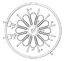
図5に、本装置を用いて、または図1から図4までに示した方法を用いて得られたガスバッグが、概略を示した自動車の操舵輪30上に配置されて示されている。図5には、平坦な上側と平坦な下側とをもつ包装を形成するガスバッグの緊密な形状が明らかに見られる。独立の壁フラップ28が、折り畳まれたガスバッグの中心回りに星状に配置されている。折り畳まれたガスバッグは、ガスバッグ搭載部の高さに対応する包装高さ“a”を有している。ガスバッグを固定するため、ガスバッグ回りにバンド32が設けられている。
【0030】
図6に本発明の他の実施例の概略が示されている。運転者側のガスバッグを示す図1から図4までのものとは対照的に、図6においては、乗客側のガスバッグが折り畳まれる。このガスバッグは一般に、圧力を加えない初期状態において、1つの平面内に平坦に拡げることが不可能であり、その意味から3次元ガスバッグと呼ばれる。図6に見るように、折り畳み要素20は、図示されていない基部16と板19との間に膨脹されたガスバッグの外周辺の形状に対応して、丸められた長方形に沿つて配置されている。図6に示したガスバッグは、形状が違うことを除けば、図1から図3のガスバッグとほぼ同様の態様で折り畳まれる。
【0031】
図7には、折り畳み舌20により折り畳まれた図6のガスバッグが見られる。乗客用のガスバッグは一般に、細長い搭載部に収容されるから、長方形に折り畳まれる。この場合も、形成された壁フラップは、折り畳まれたガスバッグの中心に関しほぼ半径方向に延びている。
【0032】
図8には、本発明の方法の他の実施例により折り畳まれた乗客側のガスバッグが示されている。より明瞭にするため、折り畳みに使用される折り畳み舌だけが図示されており、本実施例においても、装置は、図1および図2に示した要素、特に、その間にガスバッグがその包装高さにまで展開される基部と板とを有している。ガスバッグ展開後、第1に、ガスバッグ10の長手方向軸xに平行に配置された第1折り畳み舌120が、ガスバッグの内部に向かつて動かされる。この際、折り畳み舌120は先ず、折り畳み舌により画定される平面内で直線に沿つてガスバッグ10の内部へ向かつて動かされ、続いて、平行状態を保ちつつ互いに向かつて変移され、最後に、折り畳み舌により画定される平面内で再び互いに向かつて動かされる。この方法で達成された最後に位置において、折り畳み舌が番号120’で示されている。折り畳み舌120によりカバーされる経路が番号120”で示されている。壁フラップ28が折り畳み舌120’の間に形成されている。
【0033】
図11に見るように、図示の折り畳み舌120に加えて、軸x上に配置され、平行変移をすることなく軸xに沿つてガスバッグ10の内部に向かつて動く2個の折り畳み舌121を使用してもよい。最終位置において、この折り畳み舌が番号121’で示されている。
【0034】
図10には、折り畳み舌121に垂直に延びる他の折り畳み舌122’が見られる。この折り畳み舌122’は、図9の折り畳み段階において生じた外側に位置する壁フラップ28内へと押し付けられる。折り畳み舌122が押し付けられた状態の図10に示すガスバッグは、大きい壁フラップが外側に存在しているため、クローバーの葉を思い起こさせる。
【0035】
図11には、ガスバッグを折り畳む最終段階が示されている。この段階は、追加の折り畳み舌123が、先行の折り畳み段階の後に存在する外側壁フラップ内へ押し付けられることから成る。折り畳み舌123はそれぞれ、軸xに対して45°の角度をなして配置されている。
【0036】
従って、図8から図11までに示した本発明の実施例においては、折り畳まれるガスバッグが、3個のグループの折り畳み舌を用いて折り畳まれている。図示の実施例において、互いに対向して位置する折り畳み舌122、123から成る第1、第2グループと、第1、第2グループの間に位置する折り畳み舌120、121から成る第3グループとが使用されている。必要に応じて、これらグループに対して、図示の3個または6個の折り畳み舌よりも多い数の折り畳み舌を使用してもよい。その場合、各折り畳み舌の間に、より小さい壁フラップが形成される。
【0037】
ガスバッグ10が所望の形状に一緒に折り畳まれた後、圧力作用装置を用いて部分真空がガスバッグ内部に加えられる。ついで、折り畳み舌が、ガスバッグの壁から、ガスバッグの形状を変化させることなく引き抜かれる。その後、ガスバッグはガスバッグ搭載部に直接挿入されるか、ガスバッグが再び展開することがないようにバンドを掛けられる。
【0038】
図12は、図8から図11までに示した方法により折り畳まれたガスバッグ10の概略透視図である。ガスバッグが、包装高さに対応する板19と基部16との間の距離である高さ“a”を有することが明らかに分かる。さらに、折り畳まれたガスバッグが互いに隣接して位置する複数個の壁フラップから成ることが見られる。これら壁フラップは外側から内方へ向かつて、また、折り畳まれたガスバッグの上面にほぼ垂直に延びている。
【0039】
図13は、本発明の他の実施例に従って折り畳まれる乗客側のガスバッグを示す。本目的のため、それぞれ対をなして対向する折り畳み舌220、221が使用されている。折り畳み舌220または221は、本実施例においてもガスバッグを折り畳む装置の基部と板との間に展開されたガスバッグの壁を、内方にガスバッグの内部に向かつて、互いに離隔された4本の線に沿つて押す。かくて、クローバーの葉状に配置された4個の壁フラップ28が形成されている。
【0040】
次の段階において(図15)、軸xに平行に延びる2個の折り畳みスライダー230が、本軸に垂直にガスバッグの中心に向かつて動かされる。ついで、折り畳み舌221が外側へ引き抜かれる(図16)。
【0041】
次の段階において、軸xと折り畳みスライダー230とに垂直に延びる他の2個の折り畳みスライダー231が一緒に、外側からガスバッグ10の内部に向かつて押される(図17)。最終段階として、折り畳みスライダー231に垂直な折り畳み舌220が折り畳まれたガスバッグから引き抜かれる。今や、ガスバッグが完全に一緒に折り畳まれている。
【0042】
本発明の方法は全体として、次の2個の主な段階に基づいている:第1に、ガスバッグが、得ようとする折り畳まれたガスバッグの高さだけ互いに隔離された基部と板との間に展開され、ついで、ガスバッグの壁全体が、ガスバッグの中心に向かつて一緒に押し付けられる。これは、折り畳み舌だけによつて、または、折り畳み舌と折り畳みスライダーとを組み合わせて実行される。本発明の方法の実施例は全て、ガスバッグの壁が正確に決められた平坦な層をなして折り畳まれるのではなく、複数個の壁フラップをなして一緒に押されるという事実を共通に有している。これら壁フラップは各場合、使用される折り畳み舌を用いて精密に形成されている、しかし、壁フラップ内においては、壁のコースは決まつていない。それぞれに得られるガスバッグの折り畳みパターンは、折り畳み毎に僅かに違うことを考慮に入れておく必要がある。しかし、これらの僅かな相違は、ガスバッグの展開に対しては重要ではなく、折り畳み舌により形成される壁フラップによつてだけ、常に再現可能な展開プロセスが達成される。また、この展開プロセスに関しても、壁を一緒に押す際に壁フラップに生じるガスバッグの壁の変形は重要なことではない。
【図面の簡単な説明】
【図1】運転者側のガスバッグと、本発明の方法を実行するための、初期状態にある本発明の装置との概略上面図。
【図2】図1に示したガスバッグと装置との概略側面図。
【図3】図1のガスバッグと、中間状態にある装置との概略上面図。
【図4】図1から図3までに示した装置の変形の概略上面図。
【図5】図1から図3までに示す本発明の装置により折り畳まれ、自動車操舵輪上に配置された本発明のガスバッグの概略透視図。
【図6】乗客側のガスバッグと、本発明の方法を実行するための、初期状態にある本発明の装置との概略上面図。
【図7】本発明の方法を用い、図6の本発明の装置により折り畳まれた本発明のガスバッグの概略上面図。
【図8】本発明の第2実施例の方法により折り畳まれるべき、乗客側のガスバッグの概略上面図。
【図9】第1折り畳み段階の後の図8のガスバッグの図。
【図10】つぎの折り畳み段階の後の図9のガスバッグの図。
【図11】最後の折り畳み段階の後の図10のガスバッグの図。
【図12】折り畳み後、ガスバッグモジュール上に置かれた図8から図11に示したガスバッグの概略透視図。
【図13】本発明の第3実施例の方法により折り畳まれるべき、乗客側のガスバッグの概略上面図。
【図14】第1折り畳み段階の後の図13のガスバッグの図。
【図15】第2折り畳み段階の後の図14のガスバッグの図。
【図16】次ぎの折り畳み段階の後の図15のガスバッグの図。
【図17】最後の折り畳み後の図16のガスバッグの図。
【符号の説明】
10 ガスバッグ
12 膨脹開口
14 縁
16 基部
18 締結装置
19 板
20、21、120、121、122、123、220、221 折り畳み舌
22 駆動装置
26 圧力作用装置
28 壁フラップ
230、231 折り畳みスライダー[0001]
BACKGROUND OF THE INVENTION
The present invention relates to a method for folding a gas bag of an automobile occupant restraint device, a folded gas bag of an automobile occupant restraint device, and an apparatus for carrying out the method. An automobile occupant restraint device usually communicates with a compressed gas source, a trigger device for the gas source, and a compressed gas source. When the compressed gas source is ignited, the restraint effect is exerted on the automobile occupant from the collapsed state of volume reduction. It consists of a gas bag that changes into an unfolding state.
[0002]
[Problems to be solved by the invention]
There are several requirements for this type of gas bag folding. The first is to change the gas bag from the folded state to the expanded state as quickly as possible. Furthermore, it is preferred that the folding can be performed automatically. This reduces the manufacturing cost of the vehicle occupant restraint device.
[0003]
[Means for Solving the Problems]
The present invention firstly provides a gas bag folding method that is performed automatically rather than manually and secondly allows a folded gas bag to be deployed in a particularly advantageous manner. The method of the present invention comprises the following steps. First, spread the gas bag over the base. Next, the edge of the inflation opening of the gas bag is fixed. Next, the plate is placed parallel to the base and spaced from the base, and a gas bag is placed between the base and the plate. Thereafter, pressure is applied inside the gas bag so that the gas bag develops between the base and the plate. Finally, the gas bag wall is pressed inward at several locations distributed around the periphery. Thus, it is possible to obtain a gas bag that is very tightly folded and easy to deploy. Compared to the conventional folding method, improvement in the time required for gas bag deployment can be seen. In addition, a more uniform deployment of the gas bag and an improved opening behavior of the cover protecting the folded gas bag can be seen. The gas bag folded according to the method of the invention is deployed particularly symmetrically, which improves the positioning of the gas bag during deployment. Due to the particularly uniform development of the gas bag, the stress experienced by the seam and the fibers of the gas bag is small compared to a gas bag folded by a conventional method. Due to the improved deployment behavior, it can be seen that the impact and energy of the deployed gas bag wall portion on the restrained vehicle occupant is significantly reduced compared to gas bags folded by conventional methods. . The method of the present invention can be applied to a driver-side gas bag having a two-dimensional shape in an unpressurized initial state and a passenger-side gas bag having a normal three-dimensional shape in an unpressurized initial state.
[0004]
According to a preferred embodiment of the invention, the wall is pressed inward by several folding tongues that are isolated from each other, each tongue engaging along a line on the wall of the gas bag, between the folding tongues. A wall flap is formed. The folding tongue provides a particularly simple means of pressing the gas bag wall inwardly at several positions isolated from one another in order to fold the gas bag tightly together.
[0005]
According to a preferred embodiment of the invention, the wall is pressed inward in two stages and the wall flap formed in the first stage is pressed inward in the second stage. Thus, a gas bag is obtained in which the wall is folded very uniformly and is folded very tightly.
[0006]
According to a preferred embodiment of the invention, the folding tongue is pressed along the straight line into the interior of the gas bag. Thus, the method of the invention can be carried out particularly simply.
[0007]
Further, the folding tongue can be displaced while being kept in a parallel state while being pressed against the inside of the gas bag. The method is particularly advantageous in passenger-side gas bags, because the folding tongue can be translated in parallel, so that even a gas bag having an elongated initial shape can be folded tightly.
[0008]
According to a preferred embodiment of the present invention, the wall of the gas bag is pressed along a line perpendicular to the base and the plate. Thus, it is ensured that the gas bag wall moves only once outwardly during deployment without substantially changing direction, and that the gas bag reaches a fully deployed shape.
[0009]
According to a preferred embodiment of the present invention, after the wall of the gas bag is pushed inward by the folding tongue, the wall is pushed together by the folding slider to the inside of the gas bag. Due to the combination of the folding tongue and the folding slider, the method of the invention can be carried out with very little effort. The folding tongue that is first moved into the wall of the gas bag essentially determines the folding pattern to be achieved. However, instead of tightly folding the entire wall of the gas bag using a plurality of folding sliders, it is also possible to press the walls tightly in a simple manner using a smaller number of folding sliders.
[0010]
According to a preferred embodiment of the present invention, the wall is pushed into the interior of the gas bag by four folding sliders, and the two folding sliders are located in a pair and facing each other. Four folding tongues facing each other are used. The use of four folding tongues and four folding sliders provides a good compromise, on the one hand achieving a reproducible folding of the gas bag and on the other hand reducing the effort to carry out the method. To do.
[0011]
According to a preferred embodiment of the present invention, an excess pressure of 100000 Pa (pascal) or less is applied to the interior of the
[0012]
According to a preferred embodiment of the present invention, after the pressure is applied, the gas inside the gas bag can escape while the folding tongue or folding slider is being pressed. Thus, the energy required to push the folding tongue or folding slider into the wall of the gas bag is kept low.
[0013]
Furthermore, after folding the gas bag, a partial vacuum (incomplete vacuum) can be applied to the inside of the gas bag. Thus, the folded gas bag has a tighter shape, and at the same time can maintain the folded shape until it is secured elsewhere, especially after removing the folding element.
[0014]
Preferably, the base is arranged away from the plate by a distance approximately equal to the packaging height of the folded gas bag. The packaging height represents the height occupied by the gas bag inside the mounting portion in which the gas bag is accommodated. If the distance between the base and the plate corresponds to the packaging height, the gas bag folded by the folding tongue or folding slider can be inserted directly into the mounting part without further folding or re-molding .
[0015]
The present invention also provides a gas bag for an automobile occupant restraint device having an inflatable opening in a wall of the gas bag, wherein the gas bag wall extends to form a wall flap located adjacent to each other. Provide a gas bag. Such a gas bag can be deployed in a particularly advantageous manner. See the above description for the benefits obtained.
[0016]
According to a preferred embodiment of the folded gas bag of the present invention, the wall flaps extend approximately radially with respect to the center of the gas bag, as viewed in a plane parallel to the plane of the inflating opening. A particularly uniform deployment behavior of the gas bag is thus obtained.
[0017]
According to a preferred embodiment, the gas bag further has a substantially flat upper side and a substantially flat lower side parallel to the upper side, and the surface of the expansion opening is parallel to the lower side. The gas bag folded in such a shape can be accommodated in a manner that does not take up a large volume in a mounting portion such as a control wheel or dashboard of an automobile.
[0018]
The present invention also provides a device for folding a gas bag, a base for spreading the gas bag to be folded thereon, a fastening device for fixing the edge of the inflating opening, and a plate disposed at a certain distance in parallel to the base; A device for applying pressure to the inside of the gas bag fixed by the fastening device, a position spaced from the periphery of the gas bag deployed between the base and the plate, and the gas bag wall facing inward and inward It has several folding tongues that can move between the pressed positions, and the distance between the base and the plate is such that the gas bag deployed between the base and the plate has a fairly flat shape. The present invention relates to an apparatus for folding a gas bag. As mentioned above, with this device, the gas bag can be folded in a very simple and advantageous manner. See the description above for the advantages of gas bags folded together using this device.
[0019]
According to a preferred embodiment of the invention, the folding tongue moves along a straight line. Moving the folding tongue along a straight line is particularly easily achieved structurally.
[0020]
According to a preferred embodiment of the invention, the folding tongue can be displaced in a parallel manner along a part of the path towards the interior of the gas bag. Translating the folding tongue in parallel actually requires great structural effort. However, with this device, this effort is justified because even a passenger-side gas bag with an elongated shape can be folded tightly in a state where the gas bag is unfolded between the base and the plate. It becomes.
Other features of the invention will be apparent from the dependent claims.
[0021]
DETAILED DESCRIPTION OF THE INVENTION
The present invention will now be described in detail with reference to two preferred embodiments illustrated in the accompanying drawings.
1 and 2 show an outline of the apparatus of the present invention. By using the apparatus according to the method of the present invention, a gas bag as shown can be folded. An example of a folded gas bag is shown in FIG. The illustrated
[0022]
The apparatus of the present invention includes a base 16 on which a folded
[0023]
The device of the present invention further comprises several
[0024]
The method of the present invention is performed as follows using the above-described apparatus. First, the
[0025]
Subsequently, the
[0026]
FIGS. 1 to 3 show a
[0027]
FIG. 4 shows a modification to that shown in FIGS. The difference is that there are two groups of folding tongues, namely the
[0028]
After folding the
[0029]
FIG. 5 shows a gas bag obtained using this device or using the method shown in FIGS. 1 to 4 arranged on a steered
[0030]
FIG. 6 shows an outline of another embodiment of the present invention. In contrast to FIGS. 1 to 4 which show the driver side gas bag, in FIG. 6 the passenger side gas bag is folded. In general, this gas bag cannot be spread flat in one plane in an initial state where no pressure is applied, and is therefore referred to as a three-dimensional gas bag. As shown in FIG. 6, the
[0031]
FIG. 7 shows the gas bag of FIG. 6 folded by the
[0032]
FIG. 8 shows a passenger-side gas bag folded according to another embodiment of the method of the present invention. For the sake of clarity, only the folding tongue used for folding is shown, and in this embodiment too, the device has the elements shown in FIGS. 1 and 2, in particular the gas bag between which its packaging height is shown. It has a base and a plate that are expanded to the end. After the gas bag is deployed, first, the
[0033]
As shown in FIG. 11, in addition to the illustrated
[0034]
FIG. 10 shows another
[0035]
FIG. 11 shows the final stage of folding the gas bag. This stage consists of the
[0036]
Therefore, in the embodiment of the present invention shown in FIGS. 8 to 11, the folded gas bag is folded using three groups of folding tongues. In the illustrated embodiment, first and second groups of
[0037]
After the
[0038]
FIG. 12 is a schematic perspective view of the
[0039]
FIG. 13 shows a passenger-side gas bag that is folded according to another embodiment of the present invention. For this purpose, the
[0040]
In the next stage (FIG. 15), the two
[0041]
In the next stage, the other two
[0042]
The method of the present invention is generally based on the following two main steps: First, the base and the plate are separated from each other by the height of the folded gas bag to be obtained. Then the entire wall of the gas bag is pressed together towards the center of the gas bag. This is carried out with the folding tongue alone or in combination with the folding tongue and the folding slider. All embodiments of the method of the present invention have in common the fact that the walls of the gas bag are not folded in a precisely defined flat layer, but are pushed together in a plurality of wall flaps. is doing. These wall flaps are in each case precisely formed with the folding tongue used, but within the wall flap the wall course is not fixed. It is necessary to take into account that the folding patterns of the gas bags obtained are slightly different for each folding. However, these slight differences are not important for gas bag deployment, and a reproducible deployment process is always achieved only by means of the wall flap formed by the folding tongue. Also with respect to this deployment process, the deformation of the gas bag wall that occurs in the wall flap when pushing the walls together is not critical.
[Brief description of the drawings]
FIG. 1 is a schematic top view of a driver's gas bag and the device of the invention in an initial state for carrying out the method of the invention.
FIG. 2 is a schematic side view of the gas bag and apparatus shown in FIG.
FIG. 3 is a schematic top view of the gas bag of FIG. 1 and the apparatus in an intermediate state.
4 is a schematic top view of a modification of the apparatus shown in FIGS. 1 to 3. FIG.
FIG. 5 is a schematic perspective view of the gas bag of the present invention folded by the apparatus of the present invention shown in FIGS. 1 to 3 and disposed on the steering wheel of an automobile.
FIG. 6 is a schematic top view of a passenger-side gas bag and the device of the invention in an initial state for carrying out the method of the invention.
7 is a schematic top view of a gas bag of the present invention folded by the apparatus of the present invention of FIG. 6 using the method of the present invention.
FIG. 8 is a schematic top view of a passenger-side gas bag to be folded by the method of the second embodiment of the present invention.
9 is a view of the gas bag of FIG. 8 after the first folding stage.
10 is a view of the gas bag of FIG. 9 after the next folding stage.
11 is a view of the gas bag of FIG. 10 after the final folding stage.
12 is a schematic perspective view of the gas bag shown in FIGS. 8 to 11 placed on a gas bag module after folding. FIG.
FIG. 13 is a schematic top view of a passenger-side gas bag to be folded by the method of the third embodiment of the present invention.
14 is a view of the gas bag of FIG. 13 after the first folding stage.
15 is a view of the gas bag of FIG. 14 after the second folding stage.
16 is a view of the gas bag of FIG. 15 after the next folding stage.
17 is a view of the gas bag of FIG. 16 after the final fold.
[Explanation of symbols]
DESCRIPTION OF
Claims (41)
ガスバッグ(10)を基部(16)上に拡げる段階と、
ガスバッグ(10)の膨脹開口(12)の縁(14)を固定する段階と、
板(19)を、該板(19)と基部(16)との間にガスバッグ(10)が位置するように、基部(16)に平行に距離を置いて配置する段階と、
ガスバッグ(10)が基部(16)と板(19)との間で展開するように、ガスバッグ(10)内部に圧力を加える段階であってガスバッグ(10)が基部(16)と板(19)によって完全に覆われている段階と、
ガスバッグ(10)の壁を、周縁に分布された数個の場所において内側へ押し付ける段階と、を有する方法。In the method of folding the gas bag (10) of the vehicle occupant restraint device,
Expanding the gas bag (10) onto the base (16);
Fixing the edge (14) of the inflating opening (12) of the gas bag (10);
Placing the plate (19) at a distance parallel to the base (16) such that the gas bag (10) is located between the plate (19) and the base (16);
As the gas bag (10) is deployed between the base (16) and the plate (19), the gas bag (10) plate gas bag comprising the steps of: applying pressure (10) and the base (16) inside A stage completely covered by (19) ;
Pressing the wall of the gas bag (10) inwardly at several locations distributed around the periphery.
Applications Claiming Priority (4)
| Application Number | Priority Date | Filing Date | Title |
|---|---|---|---|
| DE29618772 | 1996-10-28 | ||
| DE197021476 | 1997-01-22 | ||
| DE296187720 | 1997-01-22 | ||
| DE19702147A DE19702147B4 (en) | 1996-10-28 | 1997-01-22 | Vehicle airbag folding - by inflating airbag between support and cover plate for sliding folding blades to push side wall inwards in pleats |
Publications (2)
| Publication Number | Publication Date |
|---|---|
| JPH10129381A JPH10129381A (en) | 1998-05-19 |
| JP3868600B2 true JP3868600B2 (en) | 2007-01-17 |
Family
ID=26033283
Family Applications (1)
| Application Number | Title | Priority Date | Filing Date |
|---|---|---|---|
| JP29467997A Expired - Fee Related JP3868600B2 (en) | 1996-10-28 | 1997-10-27 | Method of folding gas bag and folding device |
Country Status (7)
| Country | Link |
|---|---|
| US (1) | US6726615B1 (en) |
| EP (1) | EP0839691B1 (en) |
| JP (1) | JP3868600B2 (en) |
| CN (1) | CN1181326A (en) |
| CZ (1) | CZ340497A3 (en) |
| ES (1) | ES2117613T3 (en) |
| PL (1) | PL322842A1 (en) |
Families Citing this family (19)
| Publication number | Priority date | Publication date | Assignee | Title |
|---|---|---|---|---|
| BR9709278A (en) * | 1996-05-28 | 1999-08-10 | Petri Ag | Airbag process for its folding and device for carrying out the process |
| DE19702799C2 (en) * | 1996-05-28 | 2000-06-08 | Petri Ag | Airbag, method for folding it and device for carrying out the method |
| DE19748499A1 (en) * | 1997-11-03 | 1999-05-06 | Takata Europ Gmbh | Method and device for compactly folding the airbag of an airbag device in vehicles |
| DE10009333A1 (en) * | 2000-02-28 | 2001-08-30 | Trw Repa Gmbh | Method for transferring an airbag for a vehicle occupant restraint system into a receptacle provided for the airbag |
| US6505855B2 (en) | 2000-04-11 | 2003-01-14 | Nihon Plast Co., Ltd. | Air bag and air bag apparatus |
| KR100723103B1 (en) * | 2000-04-11 | 2007-05-30 | 니혼 플라스트 가부시키가이샤 | Method and device for folding up air bag, and air bag |
| JP4570105B2 (en) * | 2000-04-11 | 2010-10-27 | 日本プラスト株式会社 | Airbag |
| US7431330B2 (en) * | 2002-07-25 | 2008-10-07 | Autoliv Development Ab | Inflator bag for occupant restraint device and method of manufacturing the inflator bag |
| US20040211795A1 (en) * | 2003-04-22 | 2004-10-28 | Stembler Edward R. | Airbag deployment sensor tape folding loom |
| US7248138B2 (en) * | 2004-03-08 | 2007-07-24 | Astec International Limited | Multi-layer printed circuit board inductor winding with added metal foil layers |
| JP4595499B2 (en) * | 2004-03-23 | 2010-12-08 | タカタ株式会社 | Airbag device and airbag folding method |
| JP4947761B2 (en) | 2005-10-21 | 2012-06-06 | 日本プラスト株式会社 | How to fold an airbag |
| JP5005234B2 (en) * | 2006-02-28 | 2012-08-22 | 日本プラスト株式会社 | Air bag and air bag folding method |
| JP4994735B2 (en) * | 2006-07-24 | 2012-08-08 | 日本プラスト株式会社 | Airbag folding method and airbag folding apparatus |
| CN105620790A (en) * | 2014-10-29 | 2016-06-01 | 北京航天长征飞行器研究所 | Space unfolding structure flexible body folding method |
| DE102015010978A1 (en) * | 2015-08-26 | 2017-03-02 | GM Global Technology Operations LLC (n. d. Ges. d. Staates Delaware) | Protection arrangement for an occupant of a vehicle, vehicle with the protection arrangement and method for the production of the protection arrangement |
| CN107745693B (en) * | 2017-11-07 | 2023-06-09 | 太航常青汽车安全系统(苏州)股份有限公司 | Airbag folding device |
| JP7144749B2 (en) * | 2019-05-02 | 2022-09-30 | 豊田合成株式会社 | Airbag folded body and its folding method |
| CN112622806B (en) * | 2020-12-23 | 2022-03-15 | 苏州天准科技股份有限公司 | Folding mechanism and folding method of vehicle safety air bag |
Family Cites Families (19)
| Publication number | Priority date | Publication date | Assignee | Title |
|---|---|---|---|---|
| FR2053900A5 (en) | 1970-05-14 | 1971-04-16 | Chrysler Corp | |
| DE2251493A1 (en) | 1971-10-27 | 1973-05-03 | Allied Chem | Driver's protective inflatable cushion - made of nylon and shaped for max energy absorption |
| US5022676A (en) | 1990-01-25 | 1991-06-11 | Allied-Signal Inc. | Air bag assembly and method therefor |
| ES2062579T3 (en) | 1990-02-20 | 1994-12-16 | Toyoda Gosei Kk | DEVICE AND PROCEDURE FOR FOLDING AN "AIRBAG". |
| JP3003182B2 (en) | 1990-08-20 | 2000-01-24 | タカタ株式会社 | How to fold the passenger airbag |
| US5300011A (en) * | 1992-10-14 | 1994-04-05 | The Omega Company, Inc. | Automatic airbag folding apparatus and method |
| US5360387A (en) * | 1993-02-03 | 1994-11-01 | Jamal Saklou | Bag folding system |
| US5375393A (en) | 1993-04-07 | 1994-12-27 | Automated Solutions, Inc. | Bag folding system |
| DE4422276C2 (en) | 1993-06-17 | 1996-07-11 | Petri Ag | Airbag, method for its folding and device for carrying out the folding method |
| US5391137A (en) * | 1993-10-29 | 1995-02-21 | The Omega Company Inc. | Airbag folding apparatus and method |
| US5456651A (en) | 1993-11-08 | 1995-10-10 | Automated Solutions, Inc. | Automatic bag folding apparatus |
| US5575748A (en) | 1994-03-10 | 1996-11-19 | The Omega Company, Inc. | Airbag folding engine adaptable for folding a plurality of airbag designs |
| DE4440845A1 (en) | 1994-11-15 | 1996-05-23 | Trw Repa Gmbh | Method for folding an airbag for a vehicle occupant restraint system, device for carrying it out, and airbag folded according to the method |
| US5538281A (en) | 1995-03-31 | 1996-07-23 | Trw Vehicle Safety Systems Inc. | Folded air bag |
| DE19516494C1 (en) * | 1995-05-05 | 1996-10-24 | Autoliv Dev | Method of folding an airbag for an occupant restraint system |
| DE19535565C2 (en) | 1995-09-12 | 2002-09-05 | Takata Petri Ag | Process for folding an airbag and device for carrying out the folding process |
| US5615915A (en) * | 1996-05-06 | 1997-04-01 | Trw Inc. | Air bag folding method |
| BR9709278A (en) | 1996-05-28 | 1999-08-10 | Petri Ag | Airbag process for its folding and device for carrying out the process |
| US5782737A (en) * | 1996-07-29 | 1998-07-21 | Ford Global Technologies, Inc. | Method of folding a vehicle safety airbag |
-
1997
- 1997-10-23 US US08/956,716 patent/US6726615B1/en not_active Expired - Lifetime
- 1997-10-24 ES ES97118525T patent/ES2117613T3/en not_active Expired - Lifetime
- 1997-10-24 EP EP97118525A patent/EP0839691B1/en not_active Expired - Lifetime
- 1997-10-27 CN CN97121193A patent/CN1181326A/en active Pending
- 1997-10-27 JP JP29467997A patent/JP3868600B2/en not_active Expired - Fee Related
- 1997-10-27 PL PL97322842A patent/PL322842A1/en unknown
- 1997-10-27 CZ CZ973404A patent/CZ340497A3/en unknown
Also Published As
| Publication number | Publication date |
|---|---|
| JPH10129381A (en) | 1998-05-19 |
| EP0839691B1 (en) | 2001-10-04 |
| ES2117613T3 (en) | 2002-03-16 |
| CN1181326A (en) | 1998-05-13 |
| ES2117613T1 (en) | 1998-08-16 |
| CZ340497A3 (en) | 1998-05-13 |
| PL322842A1 (en) | 1998-05-11 |
| US6726615B1 (en) | 2004-04-27 |
| EP0839691A1 (en) | 1998-05-06 |
| MX9708283A (en) | 1998-08-30 |
Similar Documents
| Publication | Publication Date | Title |
|---|---|---|
| JP3868600B2 (en) | Method of folding gas bag and folding device | |
| JP3355350B2 (en) | Method and apparatus for folding an airbag for an airbag module | |
| JP2830963B2 (en) | Airbag | |
| JP4449452B2 (en) | Crew protection device | |
| US5492367A (en) | Method and system for folding an air bag | |
| US5300011A (en) | Automatic airbag folding apparatus and method | |
| US6341800B1 (en) | Gas bag folding system, gas bag folding process and device | |
| GB2279046A (en) | Airbag process for folding same and apparatus for carrying out the process | |
| JP2014532587A (en) | Knee airbag folding pattern and assembly and related methods | |
| JP3424421B2 (en) | Airbags and how to fold them | |
| JPH06191367A (en) | Expandable air bag | |
| JPH1120587A (en) | Air bag device | |
| JP2021160504A (en) | Airbag device for driver seat | |
| JP2009101758A (en) | Airbag device for knee protection | |
| US6619691B1 (en) | Passenger-side airbag device | |
| AU2006256300B2 (en) | Air bag device | |
| JP2709024B2 (en) | Airbag assembly | |
| EP1592548B1 (en) | Airbag folding method | |
| US6547279B1 (en) | Air bag apparatus | |
| US5795284A (en) | Method of and device for folding a gas bag of a vehicle occupant restraint system | |
| US6918868B2 (en) | Inflatable restraint system for an air bag | |
| US7090248B2 (en) | Air bag and a method of folding the air bag | |
| JP2007261565A (en) | Folding method for air bag, air bag and air bag device | |
| US6203062B1 (en) | Method of folding air bag | |
| JP3918551B2 (en) | Airbag device for passenger seat |
Legal Events
| Date | Code | Title | Description |
|---|---|---|---|
| A621 | Written request for application examination |
Free format text: JAPANESE INTERMEDIATE CODE: A621 Effective date: 20040618 |
|
| A131 | Notification of reasons for refusal |
Free format text: JAPANESE INTERMEDIATE CODE: A131 Effective date: 20060526 |
|
| A521 | Request for written amendment filed |
Free format text: JAPANESE INTERMEDIATE CODE: A523 Effective date: 20060828 |
|
| TRDD | Decision of grant or rejection written | ||
| A01 | Written decision to grant a patent or to grant a registration (utility model) |
Free format text: JAPANESE INTERMEDIATE CODE: A01 Effective date: 20060919 |
|
| A61 | First payment of annual fees (during grant procedure) |
Free format text: JAPANESE INTERMEDIATE CODE: A61 Effective date: 20061011 |
|
| R150 | Certificate of patent or registration of utility model |
Free format text: JAPANESE INTERMEDIATE CODE: R150 |
|
| LAPS | Cancellation because of no payment of annual fees |