JP3868552B2 - Music playback system - Google Patents
Music playback system Download PDFInfo
- Publication number
- JP3868552B2 JP3868552B2 JP26536296A JP26536296A JP3868552B2 JP 3868552 B2 JP3868552 B2 JP 3868552B2 JP 26536296 A JP26536296 A JP 26536296A JP 26536296 A JP26536296 A JP 26536296A JP 3868552 B2 JP3868552 B2 JP 3868552B2
- Authority
- JP
- Japan
- Prior art keywords
- music
- transmission
- reception
- information
- data
- Prior art date
- Legal status (The legal status is an assumption and is not a legal conclusion. Google has not performed a legal analysis and makes no representation as to the accuracy of the status listed.)
- Expired - Fee Related
Links
- 230000005540 biological transmission Effects 0.000 claims description 99
- 238000000034 method Methods 0.000 claims description 24
- 230000008569 process Effects 0.000 claims description 24
- 238000010586 diagram Methods 0.000 description 25
- 241001342895 Chorus Species 0.000 description 9
- 230000006870 function Effects 0.000 description 9
- HAORKNGNJCEJBX-UHFFFAOYSA-N cyprodinil Chemical compound N=1C(C)=CC(C2CC2)=NC=1NC1=CC=CC=C1 HAORKNGNJCEJBX-UHFFFAOYSA-N 0.000 description 8
- 239000012636 effector Substances 0.000 description 5
- 230000003287 optical effect Effects 0.000 description 5
- 230000005236 sound signal Effects 0.000 description 5
- 230000000694 effects Effects 0.000 description 4
- 230000003321 amplification Effects 0.000 description 3
- 238000009125 cardiac resynchronization therapy Methods 0.000 description 3
- 238000003199 nucleic acid amplification method Methods 0.000 description 3
- 230000001755 vocal effect Effects 0.000 description 3
- 230000008859 change Effects 0.000 description 2
- 230000009471 action Effects 0.000 description 1
- 238000001514 detection method Methods 0.000 description 1
- 239000004973 liquid crystal related substance Substances 0.000 description 1
- 238000012544 monitoring process Methods 0.000 description 1
- 230000004044 response Effects 0.000 description 1
Images


Landscapes
- Reverberation, Karaoke And Other Acoustics (AREA)
- Electrophonic Musical Instruments (AREA)
Description
【0001】
【発明の属する技術分野】
この発明は、楽音を再生する楽音再生装置が複数の部屋に備えられた楽音再生システムであって、各部屋にカラオケ装置が備えられたカラオケBOXで用いるカラオケシステムとして好適なものに関する。
【0002】
【従来の技術】
従来、上記カラオケシステムとしては、複数の部屋に備えられたカラオケ装置と、カラオケBOXの管理室に設けられたサーバーとが通信回線により接続されており、カラオケ装置から送信されるリクエスト信号を受信したサーバーが、そのリクエスト信号により示される選曲番号に対応する曲データをハードディスクメモリから読出して、その曲データを上記リクエスト信号を送信したカラオケ装置へ送信するものが知られている。
【0003】
【発明が解決しようとする課題】
ところで、上記カラオケBOXへ行き、ある部屋でカラオケをしており、時間切れになった場合に、利用時間を延長しようとしても、その部屋の予約がすでに入っており、他の部屋へ移動せざるを得ない場合がある。
このような場合、上記従来のカラオケシステムでは、時間切れになるまで利用していた部屋のカラオケ装置で予約していた予約曲を次に移動した部屋のカラオケ装置により再度予約しなければならず、非常に手間がかかるという問題がある。しかも、移動する前の部屋で多くの曲を予約した場合には、その予約曲および予約順を移動した部屋で正確に再現するのは困難であるという問題もある。
【0004】
そこで、本発明は、ある部屋で予約された楽曲情報の再生順序を容易、かつ、正確に他の部屋で再現するとともに、その再現された再生順序にしたがって楽曲情報を再生できる楽音再生システムの実現を目的とする。
【0005】
【課題を解決するための手段】
本発明は、上記目的を達成するため、
請求項1に記載の発明では、複数の楽音再生装置と、それらを遠隔操作可能とする遠隔操作手段とを備える音楽再生システムであって、
各楽音再生装置は、第1入力手段と、楽曲情報再生手段と、第1記憶手段と、第1送受信手段と、第1制御手段を備え、
第1入力手段は、利用者から各種入力を受け付け可能とし、
楽曲情報再生手段は、第1制御手段の制御にしたがって楽曲情報を再生し、
第1記憶手段は、楽曲の再生順序を示す再生順序情報を記憶し、
第1送信手段は、遠隔操作手段と各種信号の送受信を可能とし、
第1制御手段は、第1記憶手段に記憶する再生順序情報が示す再生順序にしたがって楽曲情報を楽曲情報再生手段に再生させると共に、第1送信処理と、第1受信処理を可能とし、
第1送信処理は、第1入力手段から送信命令が入力された場合、第1記憶手段に記憶する再生順序情報を設定情報として第1送受信手段に送信させる処理であり、
第1受信処理は、第1送受信手段が受信した設定情報中の再生順序情報を第1記憶手段に記憶させる処理であり、
遠隔操作手段は、第2入力手段と、第2送受信手段と、第2制御手段と、第2記憶手段とを備え、
第2入力手段は、利用者から各種入力を受け付け可能とし、
第2送受信手段は、楽音再生装置と各種信号の送受信を可能とし、
第2制御手段は、第2受信処理と、第2送信処理を可能とし、
第2受信処理は、第2送受信手段が受信した設定情報を第2記憶手段に記憶させる処理 であり、
第2送信処理は、第2入力手段から送信命令が入力された場合、第2記憶手段に記憶する設定情報を第2送受信手段に送信させる処理であるという技術的手段を採用する。
【0006】
請求項2に記載の発明では、請求項1に記載の楽音再生システムにおいて、楽音再生装置は、第3記憶手段を備え、
第3記憶手段は、楽曲情報の所定部分の再生禁止を示す設定状態情報を記憶し、
第1制御手段は、設定状態情報にしたがって楽曲情報を楽曲情報再生手段に再生させ、
第1送信処理は、第3記憶手段が記憶する設定状態情報も設定情報として第1送受信手段に送信させ、
第1受信処理は、第1送受信手段が受信した設定情報中の設定状態情報を第3記憶手段に記憶させるという技術的手段を採用する。
【0007】
請求項3に記載の発明では、請求項1または請求項2に記載の楽音再生システムにおいて、楽音再生装置は、第4記憶手段を備え、
第4記憶手段は、少なくとも楽曲情報の音程を示す調整状態情報を記憶し、
第1制御手段は、調整状態情報にしたがって楽曲情報を楽曲情報再生手段に再生させ、
第1送信処理は、第4記憶手段が記憶する調整状態情報も設定情報として第1送受信手段に送信させ、
第1受信処理は、第1送受信手段が受信した設定情報中の調整状態情報を第4記憶手段に記憶させるという技術的手段を採用する。
【0008】
請求項4に記載の発明では、請求項1ないし請求項3のいずれか1つに記載の楽音再生システムにおいて、楽音再生装置は、第1表示手段を備え、
第1制御手段は、第1記憶手段が記憶する再生順序情報を第1表示手段に表示させるという技術的手段を採用する。
【0009】
請求項5に記載の発明では、請求項1ないし請求項4のいずれか1つに記載の楽音再生システムにおいて、遠隔操作手段は、第2表示手段を備え、
第2制御手段は、第2受信処理の終了時、記憶が終了したことを第2表示手段に表示させるという技術的手段を採用する。
【0010】
請求項6に記載の発明では、請求項1ないし請求項5のいずれか1つに記載の楽音再生システムにおいて、楽音再生手段は、楽曲情報を受信する楽曲情報受信手段を備えるという技術的手段を採用する。
【0012】
【作用】
請求項1ないし請求項6に記載の発明では、楽音再生装置に記憶されている再生順序情報を遠隔操作手段へ送信し、その遠隔操作手段により記憶することができ、また、その遠隔操作手段に記憶されている再生順序情報を遠隔操作手段から楽音再生装置へ送信し、その楽音再生装置に記憶することができる。
たとえば、後述する発明の実施の形態に記載するように、ある部屋でカラオケをしているときに、他の部屋へ移動しなければならなくなった場合に、上記ある部屋のカラオケ装置に記憶されている予約曲リストデータを送信器へ送信して記憶させ、この記憶された予約曲リストデータを上記送信器から他の部屋のカラオケ装置へ送信して記憶させることができる。そして、その記憶された予約曲リストデータにより示される再生順序にしたがって曲データを再生できる。
つまり、ある部屋で予約した曲を他の部屋で選曲し直す手間を省くことができる。
【0014】
請求項2では、たとえば、後述する発明の実施の形態に記載するように、ある部屋のカラオケ装置に、曲の3コーラス以降、または、後奏部分の再生を禁止する再生モードが設定されている場合に、その再生モードを示す再生モードデータをカラオケ装置から送信器へ送信して記憶させることにより、他の部屋へ移動した場合であっても、その送信器に記憶されている再生モードデータを上記他の部屋のカラオケ装置へ送信することにより、そのカラオケ装置に設定されている再生モードを変更することができる。
したがって、移動した部屋において、再生モードを再度設定する手間を省くことができる。
【0016】
請求項3では、たとえば、後述する発明の実施の形態に記載するように、ある部屋のカラオケ装置において、音程、エコー、ディレイおよび音量などを所望のレベルに調整してカラオケをしていた場合に、その調整状態を示すアンプモードデータをカラオケ装置から送信器へ送信して記憶させることにより、他の部屋へ移動した場合であっても、その送信器に記憶されているアンプモードデータを上記他の部屋のカラオケ装置へ送信することにより、そのカラオケ装置に設定されているアンプモードを変更することができる。
したがって、移動した部屋において、アンプモードを再度設定する手間を省くことができるし、移動する前の部屋の調整状態を正確に再現できるため、移動する前の部屋と同じ音響条件で歌うことができる。
【0017】
さらに、請求項4に記載の発明では、楽曲情報の再生順序を知ることができる。また、送信された再生順序情報が書き込まれた場合には、その書込により新しくなった再生順序を知ることができる。
【0018】
またさらに、請求項5に記載の発明では、受信された再生順序情報の記憶が終了したことを知ることができる。
したがって、たとえば、後述する発明の実施の形態に記載するように、カラオケ装置から送信される予約曲リストデータの記憶を終了したことが、送信器に設けられた記憶終了表示用LEDの点灯により表示されるため、その点灯を確認してから部屋を移動することができる。
【0019】
そしてさらに、請求項1ないし請求項5のいずれか1つに記載の技術的手段は、請求項6に記載の発明のように、上記楽曲情報を受信する楽曲情報受信手段が備えられており、受信された楽曲情報を再生する楽音再生システムにおいて好適に用いられる。
たとえば、後述する発明の実施の形態に記載するように、曲データを通信回線を介して受信するカラオケ装置にあっては、選曲から曲データの受信までの時間が、従来のように曲データが記録された光ディスクを再生するカラオケ装置よりも短く、その分、カラオケ装置に多くの曲を予約できることから、多くの曲を予約した場合、移動した部屋において曲の予約を再入力するのは非常に手間が掛かる。
しかし、上記技術的手段を用いれば、カラオケ装置に記憶されている予約曲リストデータを送信器に記憶させ、その送信器から移動した部屋のカラオケ装置に記憶させることができるため、移動した部屋において曲の予約を再入力する手間を省くことができる。
【0020】
【発明の実施の形態】
以下、本発明の楽音再生システムの実施形態について図を参照して説明する。
なお、以下の実施形態では、楽音再生システムの一例として、カラオケ装置が設置された部屋を複数有する、いわゆるカラオケBOXで用いられるカラオケシステムを代表に説明する。また、カラオケ装置としては、通信回線を介して曲が提供される、いわゆる通信カラオケ装置が用いられるものとする。
【0021】
まず、上記カラオケシステムの主要構成について、それを示す図1を参照して説明する。
図1に示すように、カラオケシステム1は、AないしJまでの10室の部屋2,2・・を有し、各部屋2には、楽音再生装置たるカラオケ装置10がそれぞれ設置されている(図2参照)。各カラオケ装置10には、LANボード54がそれぞれ備えられており、各LANボード54は、それぞれHUB4を介して通信回線5に接続されており、この通信回線5は、管理室3に備えられたHUB4に接続されている。
【0022】
その管理室3に備えられたHUB4は、楽曲情報たる曲データの配信などを行うサーバー52に備えられたLANボード54に接続されている。サーバー52は、図示しないコンピュータを備えており、後述するように、カラオケ装置10からのリクエスト信号に応えて曲データを送信する。サーバー52には、曲データが蓄積されたハードディスクドライブ(以下、HDDと略称する)6と、曲データの蓄積状態などをCRTにより表示するモニタ7とが接続されている。
【0023】
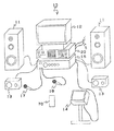
次に、カラオケ装置10の主要構成について、それを示す図2を参照して説明する。
図2に示すように、カラオケ装置10には、カラオケ用の背景映像、歌詞を示す歌詞映像、曲の予約状況を示す映像などをCRTに表示するモニタ12と、歌い手のモニタ用のモニタ14とが備えられている。また、通信回線5を介しての曲データの受信、選曲、曲の予約、選曲番号を示す選曲番号データが予約された順序に並んでいるデータ(以下、予約曲リストデータと略称する)の他の部屋との送受信、表示手段たるモニタ12,14に表示される映像の切替え、合成、分割などの各種制御を行う制御装置20が備えられている。
【0024】
さらに、マイクロフォン17,18から入力される音声と楽曲たるカラオケ曲とのミキシング、音声とカラオケ曲との音量バランス、エコー調整、ディレイ調整、ミキシング信号の増幅、演奏される曲の音程制御(キーコントロール)、高音、低音の制御(トーンコントロール)などを行うアンプ16と、このアンプ16から出力される増幅信号を音として再生するフロアータイプの1組のスピーカ11,11と、天井用の1組のスピーカ13,13と、制御装置20を遠隔操作する遠隔操作手段たる送信器70とが備えられている。
なお、アンプ16、制御装置20、スピーカ11,11およびスピーカ13,13が、本発明の楽曲情報再生手段に相当する。
【0025】
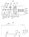
次に、制御装置20の装備について図3を参照して説明する。
図3(A)は、制御装置20の前面パネルの説明図、同図(B)は、制御装置20の背面パネルの説明図である。
図3(A)に示すように、制御装置20の前面パネルには、選曲する曲の番号の入力などを行うための0〜9のボタンからなるテンキー21と、制御装置20を選曲可能状態にし、また、選曲を確定するための選曲ボタン22とが設けられており、テンキー21の上には、選曲された曲の番号を5桁の数字でLED表示する選曲番号表示体23が設けられている。
【0026】
また、選曲番号表示体23の左には、演奏が予約されている曲の数をLED表示する予約曲数表示体24が設けられており、その下には、予約の取消を行うための取り消しボタン25と、演奏を停止させる演奏停止ボタン26と、歌っている途中で最初から歌い直すための歌い直しボタン27と、予約曲の間に割り込んで予約するための割り込みボタン28とが設けられている。これらボタンの下には、制御装置20内に記憶されている予約曲リストデータ、再生モードデータおよびアンプモードデータなどを送信器70へ送信する際に押す送信ボタン49と、この送信ボタン49を押したときに上記各データを送信する送信窓59とが設けられている。さらに、前面パネルの左上には、送信器70から送信される光信号を受光する受光窓38が設けられており、その左には、送信器70から送信された後述する再生モードデータやアンプモードデータが記憶されて新たなモードが設定されたことを示す設定終了表示用LED65が設けられている。また、受光窓38の下には、制御装置20の電源を立ち上げる電源ボタン39が設けられている。
【0027】
また、テンキー21の右には、ボーカルのメロディーラインの音量を設定するボーカルボタン32と、2コーラス目までを再生する2コーラスボタン33と曲の後奏部分をカットする後奏カットボタン34とが設けられている。
さらに、その下には、カラオケを行うモードとカラオケを行わないモードとに切り替えるカラオケ切替ボタン35と、通信回線5を介して入力されるデータを曲データからBGM、有線放送、テレビ放送などに切り替える入力切替ボタン36と、CRT12,14の表示をカラオケ店が提供しているサービス情報の表示に切り替えるサービスボタン37とが設けられている。
【0028】
また、図3(B)に示すように、制御装置20の背面パネルには、曲データを保有するサーバー52(図1参照)から配信される曲データを受信する通信回線5を接続する通信端子40が設けられており、この通信端子40の右方には、アンプ16の音声入力端子16j(図6参照)と接続される音声出力端子41と、アンプ16の入出力端子16h(図6参照)と接続される入出力端子42と、モニタ12の映像入力端子(図示省略)と接続される映像出力端子43と、モニタ14の映像入力端子(図示省略)と接続される映像出力端子44とが設けられている。
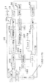
【0029】
次に、上記制御装置20の制御系の構成について、それをブロック図で示す図4を参照して説明する。
制御装置20には、曲データの送信要求、選曲、音声制御、映像制御、曲の演奏順序の予約、演奏順序の変更および送信器70との予約曲リストデータなどの送受信などをプログラムにしたがって行うCPU45が備えられている。このCPU45には、選曲された曲の番号を示す選曲番号データ、予約された曲の選曲番号データおよび送信器70から送信される予約曲リストデータなどを一時保存するRAM46と、送信器70から送信されるコマンドに対応する制御コマンドなどが記憶されたROM47と、送信器70から送信される再生モードデータ、CPU45による演算結果などを一時保存するRAM48と、アンプ16および送信器70から送信されるアンプモードデータを記憶するRAM50とが接続されている。
なお、上記RAM46、RAM48およびRAM50が、本発明の第1の記憶手段に相当する。
【0030】
また、CPU45には、サーバー52から通信回線5、通信端子40およびLANボード54を介して入力される曲データを蓄積するHDD51が接続されている。このHDD51には、上記各制御、後述する各回路の動作制御をCPU45に実行させるためのプログラムなどが記録されている。さらに、CPU45には、タイマ58のカウントにしたがって曲データに含まれるMIDIデータをMIDI音源57へ書き込む制御を行うシーケンサ56と、MIDI音源57から出力される音楽信号を入力してアンプ16により増幅可能な信号に変換する音声制御回路55とが接続されている。
【0031】
また、CPU45には、背景映像が記録されたCD−ROMを再生するCD−ROMプレーヤ60と、このCD−ROMプレーヤ60から読出された背景映像データおよびHDD51から読出された曲データ中の歌詞映像データを入力し、モニタ12,14に表示される映像として、図18に示すように、背景映像200中に歌詞映像202がスーパーインポーズされた映像を作成したり、歌詞映像202にテロップ204をかけたりする映像制御回路61が接続されている。
さらに、CPU45には、受信窓38内のフォトダイオードなどの受光素子38aにより受光された光信号をデジタル信号に変換する受信回路62と、予約曲リストデータなどを光信号に変換する送信回路66と、制御装置の前面パネルに設けられた各種ボタンを押したときに点灯するLEDおよび設定終了表示用LED65、選曲番号表示体23および予約曲数表示体24へ表示信号を出力する表示回路63と、上記各種ボタンを押したときに発生するスイッチング信号を入力する入力回路64とが接続されている。
なお、送信回路66および発光素子59aが、本発明の第1の送信手段に相当し、受信回路62および受光素子38aが、第1の受信手段に相当する。
【0032】
次に、アンプ16の構成について図5および図6を参照して説明する。
図5は、アンプ16の前面パネルの外観を示す説明図であり、図6は、アンプ16の内部構造の一部を示すブロック図である。
アンプ16の前面パネルの左上には、電源ボタン161が設けられており、その右には、主音量を調整するボリュームつまみ162と、演奏の音量を調整する演奏ボリュームつまみ163と、演奏とボーカルとの音量バランスを調整するバランスつまみ164と、演奏の低音の強弱を調整する低音調整つまみ165と、演奏の高音の強弱を調整する高音調整つまみ166とが設けられている。
【0033】
また、高音調整つまみ166の右には、マイクロフォン17から入力される音声にかけるエコーの強弱を調整するエコー調整つまみ168と、マイクロフォン18から入力される音声にかけるエコーの強弱を調整するエコー調整つまみ169と、エコーのON/OFFを行うエコースイッチ170とが設けられている。さらに、ボリュームつまみ162の下には、演奏される曲のキーを低くするためのフラットキー29と、キーを標準にする標準キー30と、キーを高くするシャープキー31とが設けられており、その下にはマイクロフォン17の出力レベルを調整するマイクレベル調整つまみ171が設けられており、その右には、マイクロフォン18の出力レベルを調整するマイクレベル調整つまみ172が設けられている。
【0034】
またさらに、その右方には、マイクロフォン17,18から入力される音声にかけるディレイの強弱を調整するディレイ調整レバー173と、マイクロフォン17,18から入力される音声の低音の強弱を調整する低音調整レバー174と、マイクロフォン17,18から入力される音声の高音の強弱を調整する高音調整レバー175とが設けられており、前面パネルの左下には、マイクロフォン17のマイクジャックを差し込むマイク端子176と、マイクロフォン18のマイクジャックを差し込むマイク端子177とが設けられている。
なお、上記各種つまみおよびレバー161ないし175および制御回路16dが、本発明の調整手段に相当する。
【0035】
次に、アンプ16の内部には、図6に示すように、マイク端子176,177から入力される音声信号をエコーやディレイなどの効果が掛かった音声信号に変換するエフェクタ回路16eが設けられており、音声入力端子16jには、この音声入力端子16jから入力される音楽信号の音程を制御する音程制御回路16fが接続されている。エフェクタ回路16eから出力される音声信号と、音程制御回路16fから出力される音楽信号とは、ミキシング回路16aによりミキシングされ、このミキシング回路16aから出力されるミキシング信号は、次段の増幅回路16bにより増幅され、この増幅された増幅信号は、スピーカ端子16cからスピーカ11,11およびスピーカ13,13へ出力され、これら両スピーカにより再生される。
【0036】
また、エフェクタ回路16e、音程制御回路16fおよび増幅回路16bは、制御回路16dから出力される制御信号により制御されており、その制御信号のレベルは、上記各調整つまみおよび調整レバー162ないし175の操作により変化する。制御回路16dから出力される制御信号は、CPU178により取り込まれ、その制御信号により示されるレベルの大きさは、アンプモードデータとしてRAM179に一時記憶される。上記各調整つまみおよび調整レバー162と制御回路16dとの間には、トランジスタにより構成されるスイッチ180が接続されており、このスイッチ180は、CPU178から出力されるスイッチング信号によりON、または、OFFする。
【0037】
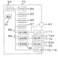
次に、送信器70の構成について図7ないし図10を参照して説明する。
図7(A)は、送信器70の表面の外観を示す説明図であり、図7(B)は、送信器70の裏面の外観を示す説明図である。図8は、送信器70の内部構造の一部を示すブロック図であり、図9は、送信器70から送信される送信信号の説明図である。図10(A)は、送信データの一例を示す説明図であり、図10(B)は、識別データの説明図である。
送信器70には、選曲された曲の選曲番号、制御装置20の送信窓59から送信される送信信号を受信中であることを示すメッセージ、送信器70から制御装置20へ送信信号を送信中であることおよび送信を終了したことを示すメッセージなどを液晶ディスプレイにより表示する表示部71が設けられている。
【0038】
この表示部71の下には、アンプ16に設けられたボタンと同じ作用を行うフラットキー72、標準キー73、シャープキー74、テンキー75、選曲キー76が設けられている。それらボタンの下には、制御装置20の再生モード、または、アンプモードを送信器70から送信された新たなモードに変更して設定する場合に押す設定ボタン92と、制御装置20から送信される送信信号に含まれる予約曲リストデータ、再生モードデータおよびアンプモードデータなどの記憶が終了したことをLEDにより表示する記憶終了表示用LED93と、送信器70に記憶されている各データを制御装置20へ送信する場合に押す送信ボタン77と、制御装置20から送信される各データを受信する場合に押す受信ボタン78とが設けられている。
【0039】
次に、送信器70の裏面には、電池の収容部を覆う電池カバー81が設けられており、その下には、送信器70を送信モード、または、受信モードに切り替えるためのモード切替スイッチ82が設けられている。
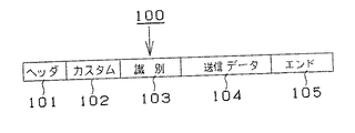
送信器70から送信される送信信号100は、図9に示すように、ヘッダデータ101と、送信器70の型式を示すカスタムデータ102と、識別データ103と、予約曲リストデータ、再生モードデータおよびアンプモードデータなどの送信データ104と、エンドデータ105とから構成される。
【0040】
識別データ103は、図10(B)に示すように、D0ないしD7の8ビットのデータから構成されており、D7は、通常の送信であるか上記各データの送信であるかを示すデータであり、たとえば、D7が「0」の場合は通常の送信を示し、「1」の場合は上記各データの送信を示す。また、D0ないしD6は、送信データ104のトータルバイト数を示す。
つまり、制御装置20において受信されたデータのバイト数が上記トータルバイト数と一致するか否かを検出して表示することにより、何らかの障害により、データが正確に受信されなかったことを知らせることができる。
【0041】
たとえば、図10(A)に示すように、送信データ104が、選曲番号12345、選曲番号2543および選曲番号12111により示される曲を順次再生することを示す予約曲リストデータ(17バイト)と、2コーラスのみを再生するとともに後奏部分をカットすることを示す再生モードデータ(2バイト)と、音程を1つ下げる(b1)とともにエコーをレベル2に設定することを示すアンプモードデータ(2バイト)とから構成される場合は、トータルバイト数は、17バイト+2バイト+2バイト=21バイトとなる。
したがって、D0=1、D1=0、D2=1、D3=0、D4=1、D5=0、D6=0となる。
【0042】
また、送信器70の内部には、図8に示すように、制御装置20の送信窓59から送信され、受信窓80内のフォトダイオードなどの受光素子80aにより受信された信号を入力してデジタル信号に変換する受信回路90が設けられており、この受信回路90により変換されたデジタル信号を構成するデータは、CPU83により第2の記憶手段たるRAM86、または、RAM87に書き込まれる。また、それら書き込まれたデータは、CPU83により読出されるとともに、RAM84に一時保存され、更にこのRAM84から読出されるとともに、送信回路89により送信信号に変換され、送信窓79に内蔵されたLEDなどの発光素子79aから送信される。
さらに、CPU83により実行されるプログラムが記憶されたROM85と、記憶終了LED93および記憶終了表示用LED93に表示信号を出力する表示回路88と、電池91とが設けられている。
そして、上記各ボタンを押したときに、そのボタンが有する機能に対応する信号が、発光素子79aから送信される。
【0043】
次に、ある部屋でカラオケをしている者が、他の部屋へ移動した場合に、自分がいた部屋で予約した曲をその移動した部屋の予約リストに組み込んで再生する場合のカラオケ装置10の一連の動作について図を参照して説明する。
なお、ここではA室からB室へ移動したものとする。
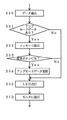
図11は、カラオケ装置10の制御装置20に備えられたCPU45の主な制御内容を示すフローチャートである。図12は、A室のカラオケ装置で記憶された予約曲リストデータを送信器に記憶させる場合のCPUの制御内容を示し、右側のフローチャートがA室の制御装置20のCPU45の制御内容であり、左側のフローチャートが送信器70のCPU83の制御内容である。図13は、送信器70に記憶された予約曲リストデータをB室の制御装置20に記憶させる場合のCPUの制御内容を示し、左側のフローチャートが送信器70のCPU83の制御内容であり、右側のフローチャートがB室の制御装置20のCPU45の制御内容である。
【0044】
まず、A室で使用している送信器70の裏面に設けられたモード切替スイッチ82を受信側にスライドさせて受信モードに切り替える(図12のステップ200)。続いて、送信器70の受信ボタン78を押して受信待機状態に設定する(ステップ210)。そして、送信器70の受信窓80をA室の制御装置20の送信窓59に向けて制御装置20の送信ボタン49を押すと(ステップ270)、制御装置20内のRAM46に記憶されている予約曲リストデータが読み出されるとともに、その予約曲リストデータを含む送信信号100が送信回路66を介して送信窓59から送信される(ステップ280)。
【0045】
この送信された送信信号は、送信器70の受信窓80内の受光素子80aにより受信されるとともに、受信回路90によりデジタル信号に変換され(ステップ220)、送信信号100に含まれるエンドデータが受信されると(ステップ230)、データ受信モードが終了し(ステップ240)、受信された送信信号に含まれる予約曲リストデータがRAM86に格納され(ステップ250)、記憶終了表示用LED93が点灯する。
このように、A室のカラオケ装置10に記憶されている予約曲リストデータを送信器70に容易に記憶させることができる。
【0046】
次に、A室にいる者が、送信器70をもってB室へ移動し、送信器70に記憶されている予約曲リストデータをB室の制御装置20に記憶させる場合を説明する。
まず、送信器70のモード切替スイッチ82を送信側に切替えて送信モードに設定し(図13のステップ300)、送信器70の送信窓79を制御装置20の受信窓38に向けて送信ボタン77を押すと(ステップ310)、RAM86に記憶されている予約曲リストデータが読出され(ステップ320)、その予約曲リストデータを含む送信信号100が、送信回路89を介して送信窓79内の発光素子79aから送信される(ステップ330)。
【0047】
その送信された送信信号100は、制御装置20の受信窓38内の受光素子38aを介して受信回路62により受信され(ステップ340)、受信された送信信号に含まれる予約曲リストデータがRAM46に書き込まれ(ステップ350)、図19に示すように、モニタ12,14に予約曲リストデータに基づく予約曲リストを示す予約曲リスト映像206が表示される(ステップ370)。
【0048】
このように、本実施形態のカラオケシステムによれば、A室からB室へ移動する場合に、A室において記憶されている予約曲リストデータを送信器70に記憶させ、その送信器70に記憶されている予約曲リストデータをB室のカラオケ装置10に記憶させることができる。
したがって、移動した部屋において曲の再生を予約し直す手間を省くことができる。
【0049】
次に、B室でカラオケする場合のカラオケ装置10の一連の動作について図11のフローチャートを参照して説明する。
選曲が終了すると(ステップ100)、RAM46に記憶されている予約曲リストデータの中の第1番目の曲番号データに対応する曲データの送信要求を示すリクエスト信号がサーバー52へ送信される(ステップ110)。すると、サーバー52は、自己のHDD15から上記リクエスト信号に示される曲番号に対応する曲データを検索して読出し、その読出された曲データは、通信回線5を介して制御装置20により受信され(ステップ120)、HDD51への一時保存が開始される。
【0050】
続いて、曲データのHDD51への保存が終了すると、HDD51から曲データが読出され、曲データに含まれる歌詞映像データは、映像制御回路61に入力され、モニタ12,14に表示可能な歌詞映像信号に変換される。また、曲データには、曲のジャンルを特定するジャンルデータが含まれており、このジャンルデータに対応する背景映像データがCD−ROMプレーヤ60により読出されるとともに、映像制御回路61に入力され、背景映像信号に変換される。
つまり、背景映像および歌詞映像は、図18に示すように、背景映像200の中に歌詞映像202がスーパーインポーズされる形で表示される。
【0051】
また、曲データに含まれるMIDIデータは、シーケンサ56に取り込まれ、タイマ58のカウントにしたがってMIDI音源57に書き込まれる。MIDI音源57から出力される音楽信号は、音声制御回路55へ出力され、アンプ16によって増幅可能な音楽信号に変換される。この変換された音楽信号は、音声出力端子41からアンプ16の音声入力端子16jへ出力され、ミキシング回路16aに入力される。また、マイクロフォン17,18から入力された音声は、音声信号となってアンプ16に内蔵されたエフェクタ回路16eにおいてエコー、または、ディレイなどの効果が掛けられ、マイクミキシング回路16bにより、上記音楽信号とミキシングされ、このミキシングされたミキシング信号は、増幅回路16cにより増幅された後にスピーカ11,11、スピーカ13,13へ出力され、両スピーカによって音楽信号および音声信号が再生される(ステップ130)。
【0052】
つまり、B室へ移動した者は、予約された曲をモニタ12,14の画面に映し出された背景映像200および歌詞映像202を見ながらマイクロフォン17,18を通して歌う(カラオケする)ことができる。
そして、予約曲リストデータがある場合には、予約曲の選曲番号データが読出され(ステップ150)、上記ステップ110ないしステップ140が繰り返される。
このように、A室で予約した曲をB室で予約順に歌うことができる。特に、時間切れになって時間を延長しようとしても、次の予約が入っているために他の部屋へ移動せざるを得ない場合があるが、そのような場合であっても、移動する前の部屋における予約状態をそのまま次の部屋で容易に再現できるため、予約のための面倒な操作をする必要がない。しかも、A室での予約数が多い場合であっても、そのままB室で正確に再現できる。
【0053】
次に、本発明第2実施形態のカラオケシステムについて図を参照して説明する。
本第2実施形態のカラオケシステムは、A室のカラオケ装置10において設定された2コーラスおよび後奏カットなどの再生モードをB室において自動的に再現して設定できることを特徴とする。
図14および図15は、制御装置20のCPU45の制御内容を示すフローチャートである。
なお、A室の制御装置20のRAM48には、上記再生モードを示す設定状態情報たる再生モードデータが記憶されている。また、予約曲リストデータがRAM46から読み出される際に、RAM48から再生モードデータも読出され、予約曲リストデータと共に送信回路66を介して送信窓59から送信器70へ送信され、送信器70のRAM87に記憶されているものとする。
【0054】
まず、B室の制御装置20は、送信器70から送信された送信信号100を受信し、その送信信号に含まれる予約曲リストデータおよび再生モードデータをRAM48に格納し(図15のステップ350)、その格納されたデータに再生モードデータが含まれている場合は(ステップ351)、モニタ12,14に「予約されている曲は、2コーラスのみで後奏部分をカットして歌う設定にしますか。設定する場合は、送信器の設定ボタンを押してください。」と表示する(ステップ352)。続いて、所定時間内に設定ボタン92が押されると(ステップ353)、制御装置20のRAM48にそれまで記憶されている再生モードデータを上記受信した新たな再生モードデータに更新し(ステップ354)、制御装置20の設定終了表示用LED65が点灯し(ステップ355)、設定終了を知らせる。
【0055】
そして、B室の制御装置20のCPU45は、図14に示すように、曲データを受信した後に(ステップ120)、RAM48に再生モードデータが記憶されているかを判定し(ステップ122)、記憶されている場合には、再生モード制御を実行する(ステップ130)。この再生モード制御は、その制御内容を示す図16のフローチャートに示すように、再生モードデータに2コーラスデータが含まれているかを判定し(ステップ131)、含まれている場合には、曲の2コーラス目の再生が終了すると(ステップ132)、メインルーチンへ戻って再生を終了する(ステップ150)。
【0056】
また、再生モードデータに2コーラスデータが含まれていない場合には、後奏カットデータが含まれているかを判定し(ステップ133)、含まれている場合には、曲の後奏部分の再生開始が検出されるのを待って(ステップ134)、メインルーチンへ戻り、再生を終了する(ステップ150)。
このように、本第2実施形態のカラオケシステムによれば、A室のカラオケ装置10に設定されていた再生モードをB室において再度設定する手間を省くことができる。
なお、設定終了表示用LED65の点灯に代えて、モニタ12,14に設定終了を示すメッセージ映像を表示するように構成することもできる。
【0057】
次に、本発明第3実施形態のカラオケシステムについて図を参照して説明する。
本第3実施形態のカラオケシステムは、A室のアンプに設定されている音程、エコー、ディレイおよび音量のレベルなどの調整状態をB室において自動的に再現して設定できることを特徴とする。
図17は、B室の制御装置20のCPU45の制御内容を示すフローチャートである。
なお、A室のカラオケ装置10に設けられたアンプ16内のRAM179には、検出回路16dからエフェクタ回路16e、音程制御回路16fおよび増幅回路16bへ出力されている制御信号のレベル、すなわち、アンプ16の調整状態を示すアンプモードデータが記憶されている。また、予約曲リストデータがRAM46から読み出される際に、RAM179からアンプモードデータも読出され、入出力端子16hから制御装置20の入出力端子42を介してRAM48に格納された後に予約曲リストデータと共に送信回路66を介して送信窓59から送信器70へ送信され、送信器70のRAM87に記憶されているものとする。
【0058】
まず、B室の制御装置20は、送信器70から送信された送信信号100を受信し、その送信信号100に含まれる予約曲リストデータおよびアンプモードデータをRAM48に格納し(図17のステップ350)、その格納されたデータにアンプモードデータが含まれている場合は(ステップ361)、モニタ12,14に「アンプの調整状態をA室のアンプと同じ状態に設定にしますか。設定する場合は、送信器の設定ボタンを押してください。」と表示する(ステップ362)。続いて、所定時間内に設定ボタン92が押されると(ステップ363)、制御装置20のRAM50にそれまで記憶されているアンプモードデータを上記受信した新たなアンプモードデータに更新し(ステップ364)、制御装置20の設定終了表示用LED65が点灯し(ステップ365)、設定終了を知らせる。
【0059】
このように、本第3実施形態のカラオケシステムによれば、B室のアンプを再度調整しなくても、A室のアンプの調整状態に、容易、かつ、正確に設定できる。
したがって、A室で歌っていたときと同じ音響効果で歌うことができるため、違和感を感じることがない。
なお、設定終了表示用LED65の点灯に代えて、モニタ12,14に設定終了を示すメッセージ映像を表示するように構成することもできる。
【0060】
上記各実施形態では、カラオケシステムとして通信カラオケ装置を用いたカラオケシステムを代表に説明したが、光ディスクに記録された曲データを再生するカラオケ装置を用いたカラオケシステムにも本発明を適用することができる。
【0061】
ところで、CPU45により実行されるステップ280が本発明の第1の送信手段として、ステップ340が第1の受信手段として、ステップ350が書込手段として、ステップ220が第2の受信手段として、ステップ250が第2の記憶手段として、ステップ300ないしステップ330が第2の送信手段としてそれぞれ機能する。
また、CPU45により実行されるステップ131ないしステップ134が本発明の再生禁止設定手段として、ステップ351ないしステップ354が設定状態変更手段としてそれぞれ機能し、CPU83により実行されるステップ260が、記憶終了表示手段として機能する。
さらに、CPU45により実行されるステップ363およびステップ364が本発明の調整状態変更手段として、ステップ370が再生順序情報表示手段として、ステップ120が楽曲情報受信手段としてそれぞれ機能する。
【0062】
【発明の効果】
以上のように、本発明によれば、ある部屋で予約された楽曲情報の再生順序を容易、かつ、正確に他の部屋で再現するとともに、その再現された再生順序にしたがって楽曲情報を再生できる楽音再生システムを実現することができる。
【図面の簡単な説明】
【図1】 本発明実施形態のカラオケシステムの主要構成を示すブロック図である。
【図2】 本発明実施形態のカラオケシステムに用いられるカラオケ装置の外観説明図である。
【図3】 (A)は、カラオケ装置に備えられた制御装置の前面パネルの説明図であり、(B)は、制御装置の背面パネルの説明図である。
【図4】 制御装置の制御系の構成を示すブロック図である。
【図5】 アンプの外観説明図である。
【図6】 アンプの主要内部構成を示すブロック図である。
【図7】 (A)は、送信器の表面の外観説明図であり、(B)は、送信器の裏面の外観説明図である。
【図8】 送信器の主要内部構成を示すブロック図である。
【図9】 送信信号の説明図である。
【図10】 (A)は送信データの説明図であり、(B)は識別データの説明図である。
【図11】 CPU45の主要制御内容を示すフローチャートである。
【図12】 右側のフローチャートは、A室のCPU45の制御内容を示し、左側のフローチャートは、送信器のCPU83の主要制御内容を示す。
【図13】 左側のフローチャートは、送信器のCPU83の主要制御内容を示し、右側のフローチャートは、B室のCPU45の制御内容を示す。
【図14】 モード制御を行う場合のCPU45の主要制御内容を示すフローチャートである。
【図15】 再生モードデータを更新する場合のCPU45の制御内容を示すフローチャートである。
【図16】 再生モード制御を行う場合のCPU45の制御内容を示すフローチャートである。
【図17】 アンプモードデータを更新する場合のCPU45の制御内容を示すフローチャートである。
【図18】 モニタに表示された背景映像および歌詞映像を示す説明図である。
【図19】 モニタに表示された予約曲リスト映像を示す説明図である。
【符号の説明】
10 カラオケ装置
11,13 スピーカ
12,14 モニタ
15,51 HDD
16 アンプ
17,18 マイクロフォン
20 制御装置
45,83 CPU
52 サーバー
5 通信回線
60 CD−ROMプレーヤ
70 送信器[0001]
BACKGROUND OF THE INVENTION
The present invention relates to a musical sound reproduction system in which a musical sound reproducing device for reproducing musical sounds is provided in a plurality of rooms, which is suitable as a karaoke system used in a karaoke BOX in which a karaoke device is provided in each room.
[0002]
[Prior art]
Conventionally, as the karaoke system, a karaoke device provided in a plurality of rooms and a server provided in a management room of the karaoke BOX are connected by a communication line, and a request signal transmitted from the karaoke device is received. It is known that a server reads music data corresponding to a music selection number indicated by the request signal from a hard disk memory and transmits the music data to the karaoke apparatus that has transmitted the request signal.
[0003]
[Problems to be solved by the invention]
By the way, if you go to the karaoke BOX and karaoke in a certain room, and you try to extend the usage time when you run out of time, the room has already been reserved and you have to move to another room. You may not get.
In such a case, in the above conventional karaoke system, the reserved tune reserved in the karaoke device in the room used until the time expires must be reserved again by the karaoke device in the next moved room, There is a problem that it is very time-consuming. In addition, when many songs are reserved in the room before moving, there is also a problem that it is difficult to accurately reproduce the reserved songs and the reservation order in the moved room.
[0004]
Therefore, the present invention realizes a music sound reproduction system that can reproduce the music information reserved in one room easily and accurately in another room, and can reproduce the music information according to the reproduced reproduction order. With the goal.
[0005]
[Means for Solving the Problems]
In order to achieve the above object, the present invention
In the invention according to
Each musical sound playback device includes first input means, music information playback means, first storage means, first transmission / reception means, and first control means.
The first input means can accept various inputs from the user,
The music information reproducing means reproduces the music information according to the control of the first control means,
The first storage means stores reproduction order information indicating the reproduction order of the music,
The first transmission means enables transmission and reception of various signals with the remote control means,
The first control means causes the music information reproduction means to reproduce the music information according to the reproduction order indicated by the reproduction order information stored in the first storage means, and enables the first transmission process and the first reception process,
The first transmission process is a process in which, when a transmission command is input from the first input unit, the reproduction order information stored in the first storage unit is transmitted to the first transmission / reception unit as setting information.
The first reception process is a process of storing the reproduction order information in the setting information received by the first transmission / reception means in the first storage means,
The remote operation means includes second input means, second transmission / reception means, second control means, and second storage means,
The second input means can accept various inputs from the user,
The second transmission / reception means enables transmission / reception of various signals to / from the music reproduction device,
The second control means enables the second reception process and the second transmission process,
The second reception process is a process for storing the setting information received by the second transmission / reception means in the second storage means. And
The second transmission process is a process for causing the second transmission / reception means to transmit the setting information stored in the second storage means when a transmission command is input from the second input means.Adopt technical means.
[0006]
According to a second aspect of the present invention, in the musical sound reproduction system according to the first aspect,The musical sound reproducing device includes third storage means,
The third storage means stores setting state information indicating prohibition of reproduction of a predetermined portion of the music information,
The first control means causes the music information reproducing means to reproduce the music information according to the setting state information,
In the first transmission process, the setting state information stored in the third storage unit is transmitted to the first transmission / reception unit as setting information,
In the first reception process, the third storage unit stores the setting state information in the setting information received by the first transmission / reception unit.Adopt technical means.
[0007]
According to a third aspect of the present invention, in the musical sound reproduction system according to the first or second aspect,The musical sound reproducing device includes fourth storage means,
The fourth storage means stores at least adjustment state information indicating the pitch of the music information,
The first control means causes the music information reproducing means to reproduce the music information according to the adjustment state information,
In the first transmission process, the adjustment state information stored in the fourth storage unit is transmitted as setting information to the first transmission / reception unit,
In the first reception process, adjustment state information in the setting information received by the first transmission / reception unit is stored in the fourth storage unit.Adopt technical means.
[0008]
According to a fourth aspect of the present invention, in the musical sound reproduction system according to any one of the first to third aspects,The musical sound reproducing device includes first display means,
The first control means displays the reproduction order information stored in the first storage means on the first display means.Adopt technical means.
[0009]
According to a fifth aspect of the present invention, in the musical sound reproduction system according to any one of the first to fourth aspects,The remote control means includes a second display means,
The second control means displays on the second display means that the storage is completed at the end of the second reception process.Adopt technical means.
[0010]
According to a sixth aspect of the present invention, in the musical sound reproduction system according to any one of the first to fifth aspects,The musical sound reproducing means includes music information receiving means for receiving music information.Adopt technical means.
[0012]
[Action]
In the invention according to
For example, as described in the embodiment of the invention to be described later, when karaoke is performed in a certain room, when it is necessary to move to another room, it is stored in the karaoke apparatus in the certain room. The reserved song list data can be transmitted to the transmitter for storage, and the stored reserved song list data can be transmitted from the transmitter to the karaoke apparatus in another room for storage. Then, the song data can be reproduced according to the reproduction order indicated by the stored reserved song list data.
That is, it is possible to save the trouble of reselecting a song reserved in one room in another room.
[0014]
In
Therefore, it is possible to save the trouble of setting the reproduction mode again in the moved room.
[0016]
In
Therefore, in the moved room, it is possible to save the trouble of setting the amplifier mode again, and the adjustment state of the room before moving can be accurately reproduced. .
[0017]
Furthermore, in invention of
[0018]
Furthermore, in the invention according to
Therefore, for example, as described in the embodiment of the invention described later, the fact that the storage of the reserved song list data transmitted from the karaoke apparatus has been completed is indicated by the lighting of the storage end display LED provided in the transmitter. Therefore, the room can be moved after confirming the lighting.
[0019]
Further, the technical means according to any one of
For example, as described in the embodiments of the invention described later, in a karaoke apparatus that receives music data via a communication line, the time from music selection to reception of music data is the same as in the past. Because it is shorter than a karaoke device that plays back recorded optical discs, and many songs can be reserved in the karaoke device, it is very difficult to re-enter the song reservation in the moved room when many songs are reserved. Take the trouble.
However, if the above technical means is used, the reserved song list data stored in the karaoke device can be stored in the transmitter and stored in the karaoke device in the room moved from the transmitter. This saves you the trouble of re-entering song reservations.
[0020]
DETAILED DESCRIPTION OF THE INVENTION
Hereinafter, embodiments of a musical sound reproduction system of the present invention will be described with reference to the drawings.
In the following embodiments, a karaoke system used in a so-called karaoke BOX having a plurality of rooms in which karaoke apparatuses are installed will be described as a representative example of a musical sound reproduction system. As the karaoke device, a so-called communication karaoke device in which music is provided via a communication line is used.
[0021]
First, the main configuration of the karaoke system will be described with reference to FIG.
As shown in FIG. 1, the
[0022]
The
[0023]
Next, the main configuration of the
As shown in FIG. 2, the
[0024]
Furthermore, the sound input from the
The
[0025]
Next, the equipment of the
3A is an explanatory diagram of the front panel of the
As shown in FIG. 3A, on the front panel of the
[0026]
Further, on the left side of the music
[0027]
To the right of the
Below that, a
[0028]
Further, as shown in FIG. 3B, a communication terminal for connecting a
[0029]
Next, the configuration of the control system of the
The
The
[0030]
The
[0031]
The
Further, the
The transmitting
[0032]
Next, the configuration of the
FIG. 5 is an explanatory diagram showing the appearance of the front panel of the
A
[0033]
Further, to the right of the
[0034]
Furthermore, on the right side, a delay adjustment lever 173 that adjusts the strength of the delay applied to the sound input from the
The various knobs and levers 161 to 175 and the control circuit 16d correspond to the adjusting means of the present invention.
[0035]
Next, as shown in FIG. 6, an effector circuit 16e for converting the audio signal input from the
[0036]
The effector circuit 16e, the
[0037]
Next, the configuration of the
FIG. 7A is an explanatory diagram showing the appearance of the front surface of the
The
[0038]
Under the display portion 71, there are provided a
[0039]
Next, a battery cover 81 is provided on the back surface of the
As shown in FIG. 9, the
[0040]
As shown in FIG. 10B, the
That is, by detecting and displaying whether or not the number of bytes of data received by the
[0041]
For example, as shown in FIG. 10A, the
Therefore, D0 = 1, D1 = 0, D2 = 1, D3 = 0, D4 = 1, D5 = 0, and D6 = 0.
[0042]
In addition, as shown in FIG. 8, a signal transmitted from a
Furthermore, a ROM 85 in which a program executed by the
When each button is pressed, a signal corresponding to the function of the button is transmitted from the light emitting element 79a.
[0043]
Next, when a person who karaokes in a certain room moves to another room, the
Here, it is assumed that the room A has moved to the room B.
FIG. 11 is a flowchart showing main control contents of the
[0044]
First, the
[0045]
The transmitted transmission signal is received by the light receiving element 80a in the
As described above, the reserved song list data stored in the
[0046]
Next, a case where a person in the room A moves to the room B with the
First, the
[0047]
The transmitted
[0048]
Thus, according to the karaoke system of the present embodiment, when moving from room A to room B, the reserved song list data stored in room A is stored in
Therefore, it is possible to save the trouble of re-booking the reproduction of the song in the moved room.
[0049]
Next, a series of operation | movement of the
When the music selection is completed (step 100), a request signal indicating a transmission request for music data corresponding to the first music number data in the reserved music list data stored in the
[0050]
Subsequently, when the music data is stored in the
That is, the background video and the lyrics video are displayed in a form in which the
[0051]
The MIDI data included in the music data is taken into the
[0052]
That is, the person who has moved to the room B can sing (karaoke) the reserved music while watching the
If there is reserved music list data, the music selection number data of the reserved music is read (step 150), and the above steps 110 to 140 are repeated.
In this way, songs reserved in the A room can be sung in the reserved order in the B room. In particular, even if you try to extend the time after the time expires, you may be forced to move to another room because the next reservation has been made. Since the reservation state in one room can be easily reproduced in the next room as it is, there is no need to perform troublesome operations for reservation. Moreover, even if the number of reservations in room A is large, it can be accurately reproduced as it is in room B.
[0053]
Next, a karaoke system according to a second embodiment of the present invention will be described with reference to the drawings.
The karaoke system of the second embodiment is characterized in that the playback modes such as 2 choruses and sequel cuts set in the
14 and 15 are flowcharts showing the control contents of the
Note that the
[0054]
First, the
[0055]
Then, as shown in FIG. 14, the
[0056]
If the playback mode data does not include 2 chorus data, it is determined whether or not the subsequent cut data is included (step 133). Waiting for the start to be detected (step 134), the process returns to the main routine to end the reproduction (step 150).
As described above, according to the karaoke system of the second embodiment, it is possible to save the trouble of setting the reproduction mode set in the
Instead of lighting the setting end display LED 65, a message image indicating the setting end may be displayed on the
[0057]
Next, a karaoke system according to a third embodiment of the present invention will be described with reference to the drawings.
The karaoke system of the third embodiment is characterized in that adjustment states such as the pitch, echo, delay, and volume level set in the amplifier in the A room can be automatically reproduced and set in the B room.
FIG. 17 is a flowchart showing the control contents of the
The
[0058]
First, the
[0059]
As described above, according to the karaoke system of the third embodiment, it is possible to easily and accurately set the adjustment state of the amplifier in the room A without adjusting the amplifier in the room B again.
Therefore, since it can sing with the same sound effect as when singing in the A room, there is no sense of incongruity.
Instead of lighting the setting end display LED 65, a message image indicating the setting end may be displayed on the
[0060]
In each of the above embodiments, a karaoke system using a communication karaoke apparatus as a karaoke system has been described as a representative. However, the present invention can also be applied to a karaoke system using a karaoke apparatus that reproduces song data recorded on an optical disc. it can.
[0061]
By the way, step 280 executed by the
Further,
[0062]
【The invention's effect】
As described above, according to the present invention, the reproduction order of music information reserved in a room can be easily and accurately reproduced in another room, and the music information can be reproduced according to the reproduced reproduction order. A music reproduction system can be realized.
[Brief description of the drawings]
FIG. 1 is a block diagram showing a main configuration of a karaoke system according to an embodiment of the present invention.
FIG. 2 is an external explanatory view of a karaoke apparatus used in the karaoke system according to the embodiment of the present invention.
FIG. 3A is an explanatory diagram of a front panel of a control device provided in the karaoke apparatus, and FIG. 3B is an explanatory diagram of a rear panel of the control device.
FIG. 4 is a block diagram showing a configuration of a control system of the control device.
FIG. 5 is an explanatory diagram of an external appearance of an amplifier.
FIG. 6 is a block diagram showing a main internal configuration of the amplifier.
7A is an explanatory diagram of the appearance of the front surface of the transmitter, and FIG. 7B is an explanatory diagram of the appearance of the back surface of the transmitter.
FIG. 8 is a block diagram showing a main internal configuration of a transmitter.
FIG. 9 is an explanatory diagram of a transmission signal.
10A is an explanatory diagram of transmission data, and FIG. 10B is an explanatory diagram of identification data.
FIG. 11 is a flowchart showing main control contents of a
FIG. 12 is a flowchart on the right side showing control contents of the
FIG. 13 is a flowchart on the left side showing main control contents of the
FIG. 14 is a flowchart showing main control contents of a
FIG. 15 is a flowchart showing the control contents of the
FIG. 16 is a flowchart showing the control contents of a
FIG. 17 is a flowchart showing the control contents of a
FIG. 18 is an explanatory diagram showing a background video and a lyrics video displayed on a monitor.
FIG. 19 is an explanatory diagram showing a reserved song list video displayed on a monitor.
[Explanation of symbols]
10 Karaoke equipment
11, 13 Speaker
12,14 monitor
15,51 HDD
16 amplifiers
17, 18 Microphone
20 Control device
45,83 CPU
52 servers
5 communication lines
60 CD-ROM player
70 Transmitter
Claims (6)
各楽音再生装置は、第1入力手段と、楽曲情報再生手段と、第1記憶手段と、第1送受信手段と、第1制御手段を備え、
第1入力手段は、利用者から各種入力を受け付け可能とし、
楽曲情報再生手段は、第1制御手段の制御にしたがって楽曲情報を再生し、
第1記憶手段は、楽曲の再生順序を示す再生順序情報を記憶し、
第1送信手段は、遠隔操作手段と各種信号の送受信を可能とし、
第1制御手段は、第1記憶手段に記憶する再生順序情報が示す再生順序にしたがって楽曲情報を楽曲情報再生手段に再生させると共に、第1送信処理と、第1受信処理を可能とし、
第1送信処理は、第1入力手段から送信命令が入力された場合、第1記憶手段に記憶する再生順序情報を設定情報として第1送受信手段に送信させる処理であり、
第1受信処理は、第1送受信手段が受信した設定情報中の再生順序情報を第1記憶手段に記憶させる処理であり、
遠隔操作手段は、第2入力手段と、第2送受信手段と、第2制御手段と、第2記憶手段とを備え、
第2入力手段は、利用者から各種入力を受け付け可能とし、
第2送受信手段は、楽音再生装置と各種信号の送受信を可能とし、
第2制御手段は、第2受信処理と、第2送信処理を可能とし、
第2受信処理は、第2送受信手段が受信した設定情報を第2記憶手段に記憶させる処理であり、
第2送信処理は、第2入力手段から送信命令が入力された場合、第2記憶手段に記憶する設定情報を第2送受信手段に送信させる処理である音楽再生システム。 A music playback system comprising a plurality of music sound playback devices and remote control means for enabling remote control of them,
Each musical sound playback device includes first input means, music information playback means, first storage means, first transmission / reception means, and first control means.
The first input means can accept various inputs from the user,
The music information reproducing means reproduces the music information according to the control of the first control means,
The first storage means stores reproduction order information indicating the reproduction order of the music,
The first transmission means enables transmission and reception of various signals with the remote control means,
The first control means causes the music information reproduction means to reproduce the music information according to the reproduction order indicated by the reproduction order information stored in the first storage means, and enables the first transmission process and the first reception process,
The first transmission process is a process in which, when a transmission command is input from the first input unit, the reproduction order information stored in the first storage unit is transmitted to the first transmission / reception unit as setting information.
The first reception process is a process of storing the reproduction order information in the setting information received by the first transmission / reception means in the first storage means,
The remote operation means includes second input means, second transmission / reception means, second control means, and second storage means,
The second input means can accept various inputs from the user,
The second transmission / reception means enables transmission / reception of various signals to / from the music reproduction device,
The second control means enables the second reception process and the second transmission process,
The second reception process is a process of storing the setting information received by the second transmission / reception means in the second storage means,
The second transmission process is a music playback system which is a process for causing the second transmission / reception means to transmit the setting information stored in the second storage means when a transmission command is input from the second input means .
第3記憶手段は、楽曲情報の所定部分の再生禁止を示す設定状態情報を記憶し、
第1制御手段は、設定状態情報にしたがって楽曲情報を楽曲情報再生手段に再生させ、
第1送信処理は、第3記憶手段が記憶する設定状態情報も設定情報として第1送受信手段に送信させ、
第1受信処理は、第1送受信手段が受信した設定情報中の設定状態情報を第3記憶手段に記憶させる請求項1に記載の音楽再生システム。 The musical sound reproducing device includes third storage means,
The third storage means stores setting state information indicating prohibition of reproduction of a predetermined portion of the music information,
The first control means causes the music information reproducing means to reproduce the music information according to the setting state information,
In the first transmission process, the setting state information stored in the third storage unit is transmitted to the first transmission / reception unit as setting information,
The music playback system according to claim 1, wherein the first reception process stores the setting state information in the setting information received by the first transmission / reception means in the third storage means .
第4記憶手段は、少なくとも楽曲情報の音程を示す調整状態情報を記憶し、
第1制御手段は、調整状態情報にしたがって楽曲情報を楽曲情報再生手段に再生させ、
第1送信処理は、第4記憶手段が記憶する調整状態情報も設定情報として第1送受信手段に送信させ、
第1受信処理は、第1送受信手段が受信した設定情報中の調整状態情報を第4記憶手段に記憶させる請求項1または2に記載の音楽再生システム。 The musical sound reproducing device includes fourth storage means,
The fourth storage means stores at least adjustment state information indicating the pitch of the music information,
The first control means causes the music information reproducing means to reproduce the music information according to the adjustment state information,
In the first transmission process, the adjustment state information stored in the fourth storage unit is transmitted as setting information to the first transmission / reception unit,
The music reproduction system according to claim 1 or 2, wherein the first reception process stores adjustment state information in the setting information received by the first transmission / reception means in the fourth storage means .
第1制御手段は、第1記憶手段が記憶する再生順序情報を第1表示手段に表示させる請求項1−3のいずれか1に記載の音楽再生システム。 The musical sound reproducing device includes first display means,
The music playback system according to any one of claims 1 to 3, wherein the first control means causes the first display means to display the playback order information stored in the first storage means .
第2制御手段は、第2受信処理の終了時、記憶が終了したことを第2表示手段に表示させる請求項1−4のいずれか1に記載の音楽再生システム。 The remote control means includes a second display means,
The music playback system according to any one of claims 1 to 4, wherein the second control means causes the second display means to display the end of the storage at the end of the second reception process .
Priority Applications (1)
| Application Number | Priority Date | Filing Date | Title |
|---|---|---|---|
| JP26536296A JP3868552B2 (en) | 1996-09-14 | 1996-09-14 | Music playback system |
Applications Claiming Priority (1)
| Application Number | Priority Date | Filing Date | Title |
|---|---|---|---|
| JP26536296A JP3868552B2 (en) | 1996-09-14 | 1996-09-14 | Music playback system |
Publications (2)
| Publication Number | Publication Date |
|---|---|
| JPH1091175A JPH1091175A (en) | 1998-04-10 |
| JP3868552B2 true JP3868552B2 (en) | 2007-01-17 |
Family
ID=17416129
Family Applications (1)
| Application Number | Title | Priority Date | Filing Date |
|---|---|---|---|
| JP26536296A Expired - Fee Related JP3868552B2 (en) | 1996-09-14 | 1996-09-14 | Music playback system |
Country Status (1)
| Country | Link |
|---|---|
| JP (1) | JP3868552B2 (en) |
Families Citing this family (6)
| Publication number | Priority date | Publication date | Assignee | Title |
|---|---|---|---|---|
| JP5665192B2 (en) * | 2011-07-30 | 2015-02-04 | 株式会社第一興商 | Karaoke music selection system using personal portable terminal |
| JP5665193B2 (en) * | 2011-07-30 | 2015-02-04 | 株式会社第一興商 | Karaoke music selection system using personal portable terminal |
| JP5360441B2 (en) * | 2011-08-31 | 2013-12-04 | ブラザー工業株式会社 | Karaoke remote control device |
| JP5472651B2 (en) * | 2011-09-29 | 2014-04-16 | ブラザー工業株式会社 | Karaoke ordering system and karaoke order management server device |
| KR101374733B1 (en) * | 2012-07-20 | 2014-03-17 | 주식회사 금영 | Coordination system and coordination method between portable terminal and karaoke apparatus using status information |
| JP2015055756A (en) * | 2013-09-12 | 2015-03-23 | 株式会社コシダカホールディングス | Karaoke system |
-
1996
- 1996-09-14 JP JP26536296A patent/JP3868552B2/en not_active Expired - Fee Related
Also Published As
| Publication number | Publication date |
|---|---|
| JPH1091175A (en) | 1998-04-10 |
Similar Documents
| Publication | Publication Date | Title |
|---|---|---|
| JP3879188B2 (en) | Music sound reproducing device and music sound reproducing system | |
| JP3872855B2 (en) | Music playback device | |
| JP3551631B2 (en) | Karaoke equipment | |
| JP3868552B2 (en) | Music playback system | |
| JP3884799B2 (en) | Karaoke system | |
| JP3871382B2 (en) | Music playback device | |
| JP5327725B2 (en) | Musical performance device | |
| JP3881738B2 (en) | Music playback device | |
| JP3963514B2 (en) | Karaoke equipment | |
| JP3703580B2 (en) | Music sound playback system | |
| JP3871379B2 (en) | Music playback device | |
| JP3958395B2 (en) | Online karaoke system | |
| JP3868544B2 (en) | Music playback device | |
| JP3947583B2 (en) | Music playback system | |
| JP3872854B2 (en) | Music playback system | |
| JPH07281687A (en) | Video karaoke equipment | |
| JPH08190392A (en) | Centralized management system for karaoke | |
| JP3614923B2 (en) | Movie playback device | |
| JP2907744B2 (en) | Karaoke central management device | |
| JPH10171478A (en) | Music playback device | |
| JPH09244676A (en) | Music playback device | |
| JPH10171480A (en) | Music playback device | |
| JPH1115486A (en) | Music playback device | |
| JPH1063284A (en) | Music playback device | |
| JPH10171482A (en) | Music playback device |
Legal Events
| Date | Code | Title | Description |
|---|---|---|---|
| RD04 | Notification of resignation of power of attorney |
Free format text: JAPANESE INTERMEDIATE CODE: A7424 Effective date: 20050905 |
|
| RD04 | Notification of resignation of power of attorney |
Free format text: JAPANESE INTERMEDIATE CODE: A7424 Effective date: 20051207 |
|
| A131 | Notification of reasons for refusal |
Free format text: JAPANESE INTERMEDIATE CODE: A131 Effective date: 20060801 |
|
| A521 | Written amendment |
Free format text: JAPANESE INTERMEDIATE CODE: A523 Effective date: 20060911 |
|
| TRDD | Decision of grant or rejection written | ||
| A01 | Written decision to grant a patent or to grant a registration (utility model) |
Free format text: JAPANESE INTERMEDIATE CODE: A01 Effective date: 20061003 |
|
| A61 | First payment of annual fees (during grant procedure) |
Free format text: JAPANESE INTERMEDIATE CODE: A61 Effective date: 20061011 |
|
| R150 | Certificate of patent or registration of utility model |
Free format text: JAPANESE INTERMEDIATE CODE: R150 |
|
| FPAY | Renewal fee payment (event date is renewal date of database) |
Free format text: PAYMENT UNTIL: 20091020 Year of fee payment: 3 |
|
| FPAY | Renewal fee payment (event date is renewal date of database) |
Free format text: PAYMENT UNTIL: 20101020 Year of fee payment: 4 |
|
| FPAY | Renewal fee payment (event date is renewal date of database) |
Free format text: PAYMENT UNTIL: 20101020 Year of fee payment: 4 |
|
| FPAY | Renewal fee payment (event date is renewal date of database) |
Free format text: PAYMENT UNTIL: 20111020 Year of fee payment: 5 |
|
| FPAY | Renewal fee payment (event date is renewal date of database) |
Free format text: PAYMENT UNTIL: 20111020 Year of fee payment: 5 |
|
| FPAY | Renewal fee payment (event date is renewal date of database) |
Free format text: PAYMENT UNTIL: 20121020 Year of fee payment: 6 |
|
| FPAY | Renewal fee payment (event date is renewal date of database) |
Free format text: PAYMENT UNTIL: 20131020 Year of fee payment: 7 |
|
| LAPS | Cancellation because of no payment of annual fees |