JP3865737B2 - Powder flow sensor - Google Patents
Powder flow sensor Download PDFInfo
- Publication number
- JP3865737B2 JP3865737B2 JP2004080855A JP2004080855A JP3865737B2 JP 3865737 B2 JP3865737 B2 JP 3865737B2 JP 2004080855 A JP2004080855 A JP 2004080855A JP 2004080855 A JP2004080855 A JP 2004080855A JP 3865737 B2 JP3865737 B2 JP 3865737B2
- Authority
- JP
- Japan
- Prior art keywords
- powder
- electrode
- flow rate
- powder flow
- measurement
- Prior art date
- Legal status (The legal status is an assumption and is not a legal conclusion. Google has not performed a legal analysis and makes no representation as to the accuracy of the status listed.)
- Expired - Fee Related
Links
Images


Description
本発明は、流路内を流れる粉体の流量を精度よく測定する粉体流量センサに関する。 The present invention relates to a powder flow rate sensor that accurately measures the flow rate of powder flowing in a flow path.
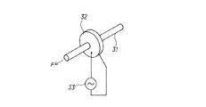
従来、粉体を切り出して搬送しようとする場合、たとえば特許文献1には自動的に粉体を切り出して定量的に搬送する方法が提案されている。すなわち、この方法は、図6に示すように、たとえばアクリル製の中空パイプ31の一端部に超音波振動を発生させる手段である圧電素子32を取り付けて、交流電源33によって交流電圧を印加する。そして、この圧電素子32によって半径方向への振動を与え、この振動によって長手方向に進行波を発生させ、他端部に向けてこの進行波を減衰することにより、中空パイプ31内を矢示F方向に粉体を搬送させようとするものである。
Conventionally, when a powder is cut out and transported, for example, Patent Document 1 proposes a method of automatically cutting out a powder and transporting it quantitatively. That is, in this method, as shown in FIG. 6, for example, a
また特許文献2には粉体の静電容量の変化を検出する流量センサが記載されている。
しかしながら、上記した従来法で粉体を微量ずつ切り出しをしようとする場合は、圧電素子32へ印加する交流電圧の調整に時間がかかるという欠点があった。特に定量ずつ切り出すバッチプロセスに適用しようとした場合は、その都度、計量升や電子秤などで計量して、その精度を確かめねばならないことから手間がかかるので、量産の工程においては正確性を犠牲にして高速化、効率化を図っているのが実情である。
However, when trying to cut out a small amount of powder by the conventional method described above, there is a drawback that it takes time to adjust the AC voltage applied to the
また特許文献2記載の流量センサにおいては、温度、湿度などの測定時の大気の環境条件によって測定値が大幅に変化するので、実用に供する精度を得るためには何らかの手段でこれらの環境変化を時間遅れなく補正しなければならないという多大な困難性がある。
Further, in the flow sensor described in
本発明は、上記のような従来技術の有する課題を解決すべくしてなされたものであって、流路内を流れる粉体の流量を連続的に高精度で測定する粉体流量センサを実現することを目的とする。 The present invention has been made in order to solve the above-described problems of the prior art, and realizes a powder flow rate sensor that continuously and accurately measures the flow rate of powder flowing in a flow path. For the purpose.
本発明は、粉体の流路に設けられ、粉体の流量を静電容量の変化として検出する測定用電極と、空気が送り込まれ、測定用電極のおかれている環境条件の変化に対応する補正に用いられる基準用電極とが、並列に設けられて構成されることを特徴とする静電容量式の粉体流量センサであり、望ましくは、前記測定用電極が粉体の流路とされる円筒管の外周に対向して配置される湾曲状の対をなすソース電極およびセンス電極と、これらの中間に設けられる一対のガード電極とで構成され、前記基準用電極が空気が送り込まれる円筒管の外周に対向して配置される湾曲状の対をなすソース電極およびセンス電極と、これらの中間に設けられる一対のガード電極とで構成されることを特徴とする請求項1記載の粉体流量センサである。
The present invention provides a measurement electrode provided in a powder flow path and detects the flow rate of the powder as a change in capacitance, and responds to changes in the environmental conditions in which air is sent and the measurement electrode is placed. And a reference electrode used for correction is a capacitance type powder flow rate sensor configured to be provided in parallel, and preferably, the measurement electrode is a powder flow path. A source electrode and a sense electrode forming a curved pair disposed opposite to the outer periphery of the cylindrical tube, and a pair of guard electrodes provided between them, and the reference electrode is fed with
本発明によれば、測定用電極と基準用電極とを併用して環境条件の変化を補正しながら、粉体に直接接触することなく、リアルタイムでかつ連続的に高い精度で流量測定を行うことができるので、例えば粉体供給装置を用いて粉体を定量切り出しする際に正確な切り出し制御を行うことができるという優れた効果を奏する。 According to the present invention, while measuring electrodes and reference electrodes are used in combination to correct changes in environmental conditions, flow measurement is performed in real time and continuously with high accuracy without directly contacting the powder. Therefore, for example, there is an excellent effect that accurate cutting control can be performed when a powder is quantitatively cut out using a powder supply device.
以下に、本発明の好適な実施の形態について、図面を参照して詳しく説明する。 Hereinafter, preferred embodiments of the present invention will be described in detail with reference to the drawings.
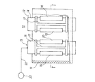
図1は本発明の一実施例の粉体流量センサの構造を一部断面で示す側面図、図2は図1のI−I矢視断面図である。 FIG. 1 is a side view showing the structure of a powder flow rate sensor according to an embodiment of the present invention in a partial cross section, and FIG. 2 is a cross sectional view taken along the line II in FIG.
図1、2に示すように、外筒11の中に粉体の流量を静電容量の変化として検出する測定用電極12と環境条件の変化に対応する補正に用いられる基準用電極13を並列に設けて構成される。
As shown in FIGS. 1 and 2, a
測定用電極12は粉体の流路とされる石英ガラス管などの円筒管14の外周に対向して配置される湾曲状の対をなすソース電極15およびセンス電極16と、これらの中間に設けられる一対のガード電極17とから構成され、基準用電極13は石英ガラス管などの円筒管18の外周に対向して配置される湾曲状の対をなすソース電極19およびセンス電極20と、これらの中間に設けられる一対のガード電極21とで構成される。基準用電極13には空気供給管22を介して空気供給装置23から空気が送り込まれる。
The
そして、測定される粉体の誘電率εを粉体流量演算制御装置7にあらかじめ回路定数として設定しておき、測定に先立って空気供給装置23から空気を基準用電極13に供給して、粉体の置かれている大気の環境条件を測定し、追って説明する図4の粉体流量演算制御装置7にその補正値として与える。
Then, the dielectric constant ε of the powder to be measured is set in advance in the powder flow rate calculation control device 7 as a circuit constant, and air is supplied from the
ついで、スタック1から粉体搬送用筒体3に供給される粉体の流量を測定用電極12で測定し、粉体流量演算制御装置7で演算処理する。このようにして、基準用電極13を用いて大気の環境条件の補正を行うことにより、静電容量式流量センサのゼロ点ドリフトを低く抑えることができるとともに、直線性を飛躍的に向上させることが可能となる。
Next, the flow rate of the powder supplied from the stack 1 to the powder transport cylinder 3 is measured by the
図3は測定電極の他の構成例を示す側面図である。この例では測定用電極12のソース電極15およびセンス電極16は、円筒管14の管軸に対して図3に示すように角度θなるらせん状に巻き付けて形成されている。このようにすることによって測定値における粉体の通過位置の影響が少なくなり、より正確な流量を測定することができる。なお、巻き付け角度θは、特開平8−271301号公報に、例えば45°とすることが示されている。しかし、この特開平8−271301号公報にはそのソース電極15およびセンス電極16のそれぞれの長さLの値については具体的に何らの記載もない。
FIG. 3 is a side view showing another configuration example of the measurement electrode. In this example, the
本発明者らは種々実験研究を重ねた結果、ソース電極15およびセンス電極16のそれぞれの長さLは角度θを45°とした場合、円筒管14を一周する360°の長さとするのがよいことを見出した。すなわち、360°とすることにより、円筒管14内を通過する際にその一断面の面内に粉体の密度差があったとしても、360°に配置されたソース電極15およびセンス電極16の全部の電束密度の位置を履歴して全距離を一通り横切って通過することになるから、平均化された値として検出されることになるのである。もし、その長さLが360°よりも小さい場合は電極を横切る距離が短くなるため誤差の要因となり、一方、360°よりも大きい場合は同じ電束密度の位置を再度履歴することになるから精度的には意味をなさないことになる。
As a result of repeating various experimental studies, the inventors have found that the length L of each of the
さらに、円筒管14を一周する360°に限らず、360°の整数倍になるようにすれば、同一粉体が同じ条件の電束密度の全部の位置にわたって確実に履歴することになるから測定精度をさらに高めることができるので好ましいといえる。逆に、一断面内の粉体の密度差がさほど問題にならない場合には、円筒管14を必ずしも360°の長さとする必要がないのはいうまでもない。
Furthermore, it is not limited to 360 ° that makes a round of the
また、測定用電極12のソース電極15およびセンス電極16の長さLを上記のように限定する場合は、当然のことながら基準用電極13の測定条件を測定用電極12と合わせるために、そのソース電極19とセンス電極20の長さも同様に限定することが望ましい。
Further, when the length L of the
つぎに本発明の粉体流量センサの使用状況の一例を図4の構成図により説明する。1は粉体2を収容するスタック、3は粉体2を搬送するアクリルなどの円筒管からなる粉体搬送用筒体で、その上端開口部はスタック1の下端供給口1aに接続される。4は粉体搬送用筒体3の水平部位3aに取り付けられる粉体供給装置であり、たとえば圧電素子を用いた超音波振動装置とか、スクリューフィーダ、テーブルフィーダ、ベルトコンベアなどが用いられる。
Next, an example of the usage state of the powder flow rate sensor of the present invention will be described with reference to the block diagram of FIG. Reference numeral 1 denotes a stack for storing the
5は粉体搬送用筒体3の垂直部位3bに取り付けられて、粉体搬送用筒体3の垂直部位3bを落下する粉体流量センサで、たとえば静電容量の原理を利用した本願の静電容量式流量センサが適当である。6はカプセルなどの粉体容器である。
7はマイコンなどの粉体流量演算制御装置であり、粉体流量センサ5からの流量信号をAD変換器を介するなどして入力して、あらかじめ与えられた目標切り出し量W(g) に基づいて粉体供給装置4に付与すべき印加電圧のレベルを演算するとともに、その演算値に基づいて制御信号を粉体供給装置4に出力して、フィードバック的に粉体容器6に投入する粉体量の制御を行う。
Reference numeral 7 denotes a powder flow rate calculation control device such as a microcomputer, which inputs a flow rate signal from the powder
このように構成することにより、スタック1に収容された粉体2は粉体供給装置4を起動することにより粉体搬送用筒体3の水平部位3aに送り出され、粉体供給装置4を通過した粉体2は垂直部位3bを経て自然落下して粉体流量センサ5を通過して粉体容器6に充填される。粉体容器6に充填される粉体2の量は、粉体流量演算制御装置7が粉体流量センサ5の出力信号を収集・分析することにより測定され、その都度粉体供給装置4を制御することによって定量切り出しが行われる。
With this configuration, the
図4の構成において、本願発明の粉体流量センサを用いて、銘柄がAPPIE(日本粉体工業技術協会)規格の標準粉体の一つである軽質炭酸カルシウムS−10の粉体を、定量2g,4g,6g,8gの4通りについてそれぞれn=5回ずつ切り出し制御を行った結果、図5に示すように、最大:4.7 %、最小:0.1 %、平均:2.5 %と高精度の成績を得ることができた。 In the configuration of FIG. 4, the powder flow rate sensor of the present invention is used to quantitatively measure light calcium carbonate S-10 powder, which is one of the standard powders of the brand name APPIE (Japan Powder Industrial Technology Association). As a result of performing control of cutting out n = 5 times for each of 4 types of 2g, 4g, 6g, and 8g, as shown in FIG. 5, the results were as follows: high: 4.7%, minimum: 0.1%, average: 2.5% Could get.
1 スタック
1a 下端供給口
2 粉体
3 粉体搬送用筒体
3a 水平部位
3b 垂直部位
4 粉体供給装置
5 粉体流量センサ
6 粉体容器
7 粉体流量演算制御装置
10 静電容量式流量センサ
11 外筒
12 測定用電極
13 基準用電極
14, 18 円筒管
15, 19 ソース電極
16, 20 センス電極
17, 21 ガード電極
22 空気供給管
23 空気供給装置
31 中空パイプ
32 圧電素子
33 交流電源
DESCRIPTION OF SYMBOLS 1 Stack 1a Lower
10 Capacitive flow sensor
11 outer cylinder
12 Measuring electrode
13 Reference electrode
14, 18 Cylindrical tube
15, 19 Source electrode
16, 20 sense electrodes
17, 21 Guard electrode
22 Air supply pipe
23 Air supply device
31 Hollow pipe
32 Piezoelectric element
33 AC power supply
Claims (2)
Priority Applications (1)
| Application Number | Priority Date | Filing Date | Title |
|---|---|---|---|
| JP2004080855A JP3865737B2 (en) | 1997-07-07 | 2004-03-19 | Powder flow sensor |
Applications Claiming Priority (2)
| Application Number | Priority Date | Filing Date | Title |
|---|---|---|---|
| JP18020897 | 1997-07-07 | ||
| JP2004080855A JP3865737B2 (en) | 1997-07-07 | 2004-03-19 | Powder flow sensor |
Related Parent Applications (1)
| Application Number | Title | Priority Date | Filing Date |
|---|---|---|---|
| JP17250498A Division JP3560816B2 (en) | 1997-07-07 | 1998-06-19 | Control method for quantitative cutout of powder |
Publications (2)
| Publication Number | Publication Date |
|---|---|
| JP2004170438A JP2004170438A (en) | 2004-06-17 |
| JP3865737B2 true JP3865737B2 (en) | 2007-01-10 |
Family
ID=32715312
Family Applications (1)
| Application Number | Title | Priority Date | Filing Date |
|---|---|---|---|
| JP2004080855A Expired - Fee Related JP3865737B2 (en) | 1997-07-07 | 2004-03-19 | Powder flow sensor |
Country Status (1)
| Country | Link |
|---|---|
| JP (1) | JP3865737B2 (en) |
Cited By (1)
| Publication number | Priority date | Publication date | Assignee | Title |
|---|---|---|---|---|
| WO2009034946A1 (en) | 2007-09-12 | 2009-03-19 | Sintobrator, Ltd. | Powder flow measuring device |
Families Citing this family (3)
| Publication number | Priority date | Publication date | Assignee | Title |
|---|---|---|---|---|
| JP4700326B2 (en) * | 2004-11-02 | 2011-06-15 | 三井金属鉱業株式会社 | Powder flow measurement device |
| JP6922412B2 (en) * | 2017-05-24 | 2021-08-18 | 株式会社リコー | Powder amount detection device and image forming device |
| JP6859240B2 (en) * | 2017-09-21 | 2021-04-14 | 日鉄エンジニアリング株式会社 | Powder and granular material blowing device, calibration curve creation device and calibration curve creation method |
-
2004
- 2004-03-19 JP JP2004080855A patent/JP3865737B2/en not_active Expired - Fee Related
Cited By (1)
| Publication number | Priority date | Publication date | Assignee | Title |
|---|---|---|---|---|
| WO2009034946A1 (en) | 2007-09-12 | 2009-03-19 | Sintobrator, Ltd. | Powder flow measuring device |
Also Published As
| Publication number | Publication date |
|---|---|
| JP2004170438A (en) | 2004-06-17 |
Similar Documents
| Publication | Publication Date | Title |
|---|---|---|
| US6420866B1 (en) | Apparatus and method for detecting metallized containers in closed packages | |
| KR870002440A (en) | Continuous measuring method of continuum | |
| JP3865737B2 (en) | Powder flow sensor | |
| US5097216A (en) | Apparatus for inspecting the wall thickness of a container and corresponding method | |
| WO1996030725A1 (en) | Device for measuring flow rate of powder, method and device for supplying powder | |
| US5532605A (en) | Container inspection apparatus having diameter measuring means and associated method | |
| JPH0342421B2 (en) | ||
| JP3560816B2 (en) | Control method for quantitative cutout of powder | |
| JP3288201B2 (en) | Powder supply device | |
| JP2008164372A (en) | Device for inspecting filled amount and its method | |
| JP2011226942A (en) | Flow measuring device for powder particles | |
| JPH11248516A (en) | Capacitive level measuring apparatus | |
| JP2022522856A (en) | Inspection stations and methods for inspecting sheet materials | |
| JP4762224B2 (en) | Method and apparatus for setting standard values for powder flow measurement | |
| JP2006091015A (en) | Method for measuring thickness of printed matter passing through measuring apparatus at predetermined intervals inside flow of conveyance line | |
| US6717087B1 (en) | Monitoring device for the sealing web width | |
| JPS6221058A (en) | Transporting system of specimen | |
| JPS5972047A (en) | Method for measuring moisture of powdered body | |
| JP2000046777A (en) | Moisture meter of high frequency capacity type | |
| JP2018112429A (en) | Combination weighing device | |
| SU566174A1 (en) | Capacitive primary transducer | |
| JPH0410978B2 (en) | ||
| JP2969297B2 (en) | Can pressure tester | |
| JPS58154622A (en) | Method and apparatus for measuring flow rate of powdered and granulated body | |
| JPS61120012A (en) | Position recognition system of conveyed material in conveying device |
Legal Events
| Date | Code | Title | Description |
|---|---|---|---|
| A621 | Written request for application examination |
Free format text: JAPANESE INTERMEDIATE CODE: A621 Effective date: 20040319 |
|
| A711 | Notification of change in applicant |
Free format text: JAPANESE INTERMEDIATE CODE: A711 Effective date: 20060405 |
|
| A521 | Written amendment |
Free format text: JAPANESE INTERMEDIATE CODE: A821 Effective date: 20060406 |
|
| TRDD | Decision of grant or rejection written | ||
| A01 | Written decision to grant a patent or to grant a registration (utility model) |
Free format text: JAPANESE INTERMEDIATE CODE: A01 Effective date: 20060926 |
|
| A61 | First payment of annual fees (during grant procedure) |
Free format text: JAPANESE INTERMEDIATE CODE: A61 Effective date: 20061003 |
|
| R150 | Certificate of patent or registration of utility model |
Free format text: JAPANESE INTERMEDIATE CODE: R150 |
|
| FPAY | Renewal fee payment (event date is renewal date of database) |
Free format text: PAYMENT UNTIL: 20101013 Year of fee payment: 4 |
|
| FPAY | Renewal fee payment (event date is renewal date of database) |
Free format text: PAYMENT UNTIL: 20111013 Year of fee payment: 5 |
|
| FPAY | Renewal fee payment (event date is renewal date of database) |
Free format text: PAYMENT UNTIL: 20121013 Year of fee payment: 6 |
|
| FPAY | Renewal fee payment (event date is renewal date of database) |
Free format text: PAYMENT UNTIL: 20121013 Year of fee payment: 6 |
|
| FPAY | Renewal fee payment (event date is renewal date of database) |
Free format text: PAYMENT UNTIL: 20131013 Year of fee payment: 7 |
|
| FPAY | Renewal fee payment (event date is renewal date of database) |
Free format text: PAYMENT UNTIL: 20131013 Year of fee payment: 7 |
|
| S111 | Request for change of ownership or part of ownership |
Free format text: JAPANESE INTERMEDIATE CODE: R313111 |
|
| FPAY | Renewal fee payment (event date is renewal date of database) |
Free format text: PAYMENT UNTIL: 20131013 Year of fee payment: 7 |
|
| R350 | Written notification of registration of transfer |
Free format text: JAPANESE INTERMEDIATE CODE: R350 |
|
| R250 | Receipt of annual fees |
Free format text: JAPANESE INTERMEDIATE CODE: R250 |
|
| R250 | Receipt of annual fees |
Free format text: JAPANESE INTERMEDIATE CODE: R250 |
|
| R250 | Receipt of annual fees |
Free format text: JAPANESE INTERMEDIATE CODE: R250 |
|
| R250 | Receipt of annual fees |
Free format text: JAPANESE INTERMEDIATE CODE: R250 |
|
| LAPS | Cancellation because of no payment of annual fees |