JP3862008B2 - Inkjet recording device - Google Patents
Inkjet recording device Download PDFInfo
- Publication number
- JP3862008B2 JP3862008B2 JP2002170282A JP2002170282A JP3862008B2 JP 3862008 B2 JP3862008 B2 JP 3862008B2 JP 2002170282 A JP2002170282 A JP 2002170282A JP 2002170282 A JP2002170282 A JP 2002170282A JP 3862008 B2 JP3862008 B2 JP 3862008B2
- Authority
- JP
- Japan
- Prior art keywords
- ink
- absorbing material
- jet recording
- platen
- ink absorbing
- Prior art date
- Legal status (The legal status is an assumption and is not a legal conclusion. Google has not performed a legal analysis and makes no representation as to the accuracy of the status listed.)
- Expired - Fee Related
Links
Images


Description
【0001】
【発明の属する技術分野】
本発明は、被記録材の端部からインクを打ち捨てることによって所謂縁無し印刷を実行可能なインクジェット式記録装置に関する。
【0002】
【従来の技術】
インクジェット式記録装置(以下「プリンタ」と言う)は、インクを吐出するインクジェット記録ヘッド(以下「記録ヘッド」と言う)と、該記録ヘッドと対向して設けられ、印刷用紙を下から支えることにより前記記録ヘッドと印刷面との距離を規定するプラテンとを有している。更にこの様なプリンタにおいては、印刷用紙に余白無く印刷を行う、所謂縁無し印刷を実行可能なものがある。
【0003】
縁無し印刷を実行可能なプリンタにおいては、前記プラテンの上面(プラテン面)に溝穴が形成される。該溝穴は、前記プラテン面において主走査方向に延びる様に形成される溝穴と、印刷用紙の端部に位置する部分に局在する様に設けられる溝穴とからなる。例えば、印刷用紙の始端が主走査方向に延びる様に形成された溝穴の上方に位置した時に、始端から外れた領域にもインクを吐出することにより、始端の縁無し印刷が行われる。つまり、前記溝穴に、インクが打ち捨てられることになる。
【0004】
ここで、一般に前記溝穴内には、インクを吸収するインク吸収材(以下これを「第1のインク吸収材」と言う)が設けられる。この様な第1のインク吸収材を設けないと、前記溝穴に打ち捨てられたインクがインクミストとなり、印刷品質の低下を招き、或いは、プリンタの駆動部品に付着して正常な印刷動作を妨げる虞があるからである。
【0005】
そして、前記溝穴の底部には、複数の貫通穴が設けられている。前記溝穴に打ち捨てられたインクは前記第1のインク吸収材に一旦吸収され、その後、前記貫通穴から下方に滴下する。従って、前記プラテンの下部には、この様に滴下するインクを受ける廃液トレイが設けられる。該廃液トレイ内には、前記溝穴と同様にインクを吸収するインク吸収材(以下これを「第2のインク吸収材」と言う)が設けられ、これにより、廃液トレイ内に貯留されたインクが、外部への漏洩しない様確実に保持される様になっている。
【0006】
【発明が解決しようとする課題】
ところで、前記溝穴に打ち捨てられたインクは前記第1のインク吸収材によって吸収されるが、この様に吸収されたインクは、その全てが前記廃液トレイに滴下するとは限らない。即ち、一部のインクは前記貫通穴から前記廃液トレイに向けて滴下するが、その他のインクは、前記第1のインク吸収材のインク保持性によって、当該第1のインク吸収材の下部に保持されたままの状態となる。
【0007】
この様な状態で例えばユーザの取り扱い或いは輸送の際に、プリンタが大きく傾いた状態に置かれると、前記第1のインク吸収材の下部に保持されたインクはプラテン端部に集中し、最悪の場合、前記溝穴から外に溢れ出る虞がある。この様な現象が発生すると、プリンタの構成要素(例えば、駆動系統或いは電気系統)に悪影響を及ぼす他、プリンタ外部にまで漏出してしまう虞もある。
【0008】
そこで本発明はこの様な問題に鑑みなされたものであり、その目的は、インクを打ち捨てる溝穴に設けられた第1のインク吸収材に吸収されたインクを、極力当該第1のインク吸収材によって保持させずに、円滑に下方に設けられた廃液トレイに導くことにある。
【0009】
【課題を解決するための手段】
上記課題を解決するために、本願請求項1記載のインクジェット式記録装置は、被記録材にインクを吐出するインクジェット記録ヘッドと、該インクジェット記録ヘッドと対向して設けられ、被記録材を下方から支持することにより記録面と前記インクジェット記録ヘッドとの距離を規定し、且つ、被記録材の端部から打ち捨てられたインクを導く溝穴が形成されたプラテンと、前記溝穴の底部に形成された複数の貫通穴から下方へ滴下するインクを受ける、前記プラテンの下部に設けられる廃液トレイと、を備えたインクジェット式記録装置であって、前記溝穴にはインクを吸収する第1のインク吸収材が、前記廃液トレイにはインクを吸収する第2のインク吸収材がそれぞれ設けられ、前記複数の貫通穴のうち少なくとも一つには、前記第1のインク吸収材から前記第2のインク吸収材へとインクを導くインクガイド手段が、前記貫通穴を挿通して上方から下方に垂下する様に設けられていることを特徴とする。
【0010】
本願請求項1記載の発明によれば、インクを打ち捨てる溝穴の底部に複数設けられた貫通穴のうち少なくとも一つには、前記第1のインク吸収材から前記第2のインク吸収材へとインクを導くインクガイド手段が、前記貫通穴を挿通して上方から下方に垂下する様に設けられているので、前記第1のインク吸収材の下部にはインクが保持されにくい。従って、インクジェット式記録装置を取り扱い時或いは輸送時等に大きく傾けた場合でも、前記第1のインク吸収材に保持されたインクが前記プラテン端部に集中し、そして外部に溢れ出るといった問題を招くことが無く、以て取り扱いや輸送の際の安全性を向上させることができる。
【0011】
尚、インクガイド手段とは、第1のインク吸収材の下部と接触して、当該下部に保持されたインクを外部へ導き出す手段を言い、例えば、第1のインク吸収材よりもインク吸収性の高い(毛細管現象の著しい)インク吸収材によって成すことができる。
【0012】
本願請求項2記載のインクジェット式記録装置は、請求項1において、前記インクガイド手段が、前記第1のインク吸収材よりもインク吸収性の高い第3のインク吸収材からなることを特徴とする。
本願請求項2記載の発明によれば、前記インクガイド手段が、前記第1のインク吸収材よりもインク吸収性の高い第3のインク吸収材からなるので、安価に且つ簡単に前記インクガイド手段を得ることができる。尚、「インク吸収性が高い」とは、毛細管現象が相対的に著しく、同一量のインクを吸収した際に、より広範囲に渡ってインクを吸収することを言う。
【0013】
本願請求項3記載のインクジェット式記録装置は、請求項1または2において、前記インクガイド手段が、前記インクジェット記録ヘッドのフラッシング動作位置近傍に形成された前記貫通穴に設けられていることを特徴とする。
【0014】
インクジェット式記録装置においては、インクジェット記録ヘッドのインクノズルが詰まることの無い様に、インクの無駄打ちを行う所謂フラッシング動作が行われる。このフラッシング動作は、インクジェット記録ヘッドの主走査領域の端部近傍にて行われる。従って、当該フラッシング動作が行われる位置においては、より多量にインクが打ち捨てられることになる。
【0015】
そこで、本願請求項3記載の発明は、前記インクガイド手段を、前記フラッシング動作が行われる位置近傍に形成された前記貫通穴に設けたので、より効果的に前記インクガイド手段の機能を発揮させることができ、もってより確実に前述したインク溢れの問題を防止することができる。
【0016】
本願請求項4記載のインクジェット式記録装置は、請求項3において、前記フラッシング動作位置は、80桁側に設定されていることを特徴とする。
本願請求項4記載の発明によれば、前記フラッシング動作位置は80桁側に設定されているので、当該80桁側に電子部品を実装した回路基板等が配置されている場合でも、前記インクガイド手段の機能によってインク溢れの問題を防止でき、前記電子部品に悪影響を与える虞が無い。
【0017】
本願請求項5記載のインクジェット式記録装置は、請求項1または2において、前記インクガイド手段が、長手方向に傾斜した状態となっている前記プラテンの、低位置側の端部近傍に形成された前記貫通穴に設けられていることを特徴とする。
【0018】
プラテンは主走査方向に長く、インクジェット式記録装置に設けられた際に、部品精度或いは組み立て精度等の影響によって長手方向に所定の角度傾いた状態となる場合がある。この様に傾くと、前記溝穴に打ち捨てられたインクは低位置側に集中し、前述したインク溢れの問題が発生し易くなる。
【0019】
そこで本願請求項5記載の発明は、前記インクガイド手段を、傾斜した状態となっている前記プラテンの、低位置側の端部近傍に形成された前記貫通穴に設けたので、インクが集中する当該低位置側においてそのインクガイド手段の機能を発揮し、以て確実に前述したインク溢れの問題を防止することができる。
【0020】
本願請求項6記載のインクジェット式記録装置は、請求項2から5のいずれか1項において、前記第2のインク吸収材のインク吸収性が、前記第3のインク吸収材のインク吸収性よりも高いことを特徴とする。
本願請求項6記載の発明によれば、前記廃液トレイに設けられた前記第2のインク吸収材のインク吸収性が、前記第3のインク吸収材のインク吸収性よりも高いので、もって確実に前記廃液トレイ内にインクを導くことが可能となる。
【0021】
【発明の実施の形態】
以下、本発明の実施の形態を図面に基づいて説明する。
図1は、本発明に係る「インクジェット式記録装置」(以下、「プリンタ」と言う)100の、上部カバーを外した状態を示す斜視図であり、図2は、プリンタ100の記録部の側断面図である。先ず、当該図1及び図2を参照しつつ、プリンタ100の大略構成について説明する。
【0022】
図1において、プリンタ100は後部に給紙装置1を備えていて、該給紙装置1に堆積・セットされる印刷用紙は、該給紙装置1によって最上位のものが1枚ずつ下流側へと搬送され、キャリッジ3の下部に設けられたインクジェット記録ヘッド(図2参照:以下「記録ヘッド」と言う)8によってインクが吐出され、記録が行われた後に、前方の排紙スタッカ5に排出される。
【0023】
キャリッジ3はインクカートリッジ4を搭載し、該インクカートリッジ4から記録ヘッド8(図2)へインクを供給する。また、キャリッジ3は、プリンタ100の基体を構成するサイドフレーム6a、6b間に掛架されたキャリッジガイド軸7を挿通し、該キャリッジガイド軸7によって主走査方向にガイドされる。そして、キャリッジ3は、図示しない駆動手段によって主走査方向に往復動作する様になっている。
【0024】
尚、図1においては右下側が「0桁側」であり、左上側が「80桁側」となっていて、キャリッジ3は、0桁側をホームポジションとし、当該0桁側において記録ヘッド8のキャッピング或いはヘッドクリーニング等のメンテナンス動作を受け、80桁側において、ノズルアレイ9(図2)のノズル穴が詰まることの無い様に、インクの無駄打ちを行う所謂フラッシング動作を行う様になっている。
【0025】
次に、図2を参照しつつプリンタ100の記録部の構成について説明する。図2において、搬送ローラ2は、回動駆動される搬送駆動ローラ2aと、該搬送駆動ローラ2aに圧接することにより従動回動する搬送従動ローラ2aとから構成されていて、上流側(図2の右側)から給紙装置1によって給紙された印刷用紙Pは、搬送駆動ローラ2aと搬送従動ローラ2bとにニップされ、記録ヘッド8の下に搬送される。
【0026】
記録ヘッド8には、インクを吐出するノズルアレイ9が設けられている。記録ヘッド8の下部に搬送された印刷用紙Pは、ノズルアレイ9からインクを吐出されることによって記録が行われる。このとき、印刷用紙Pは、記録ヘッド8の下部に、該記録ヘッド8と対向する様に設けられたプラテン10に下方から支持されることにより、ノズルアレイ9との距離(PG:ペーパーギャップ)を規定される。
【0027】
より詳しくは、プラテン9の上部にはリブ11a、11bが形成されていて(図3も参照)、印刷用紙Pは、該リブ11a、11bによって下方から支持される。リブ11bの上流側と下流側とには、それぞれ主走査方向(図2の紙面表裏方向)に延びる溝穴12a、12b(図3も参照)が形成されていて、該溝穴12a、12aに、印刷用紙Pの始端及び終端から外れたインクが打ち捨てられ、印刷用紙Pの始端側及び終端側における縁無し印刷が実行される。即ち、印刷用紙Pの始端が溝穴12bの上方に位置した時に、ノズルアレイ9の一部9bを駆動することにより、印刷用紙Pの始端から外れた部分にもインクを吐出して、始端の縁無し印刷を実行する。このとき、印刷用紙Pの始端から外れたインクが、溝穴12bに打ち捨てられる。印刷用紙Pの終端についても同様に、終端が溝穴12aの上方に位置した時に、ノズルアレイ9の一部9aを駆動することにより、印刷用紙Pの終端から外れた部分にもインクを吐出して、終端の縁無し印刷を実行する。
尚、溝穴12a、12bには、図2においては図面の簡単の為図示を省略する第1のインク吸収材17(図1及び図6参照)が設けられているが、該第1のインク吸収材16を含めたプラテン10のより詳細な構成については、後に説明する。
【0028】
次に、プラテン10の下流側には、回動駆動される排紙ローラ13が設けられている。排紙ローラ13は、回動駆動される排紙駆動ローラ13aと、該排紙駆動ローラ13aに接することにより従動回動する排紙従動ローラ13aとから構成されていて、記録ヘッド8によって記録の行われた印刷用紙Pは、排紙駆動ローラ13aと排紙従動ローラ13bとにニップされ、排紙スタッカ5(図1)の下に搬送される。
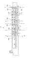
以上がプリンタ100の大略構成であり、以下、プラテン10の構成について図3乃至図6を参照しつつ説明する。ここで、図3はプラテン10の外観斜視図、図4は同平面図、図5はプリンタ100を左右方向に切断して要部を示した要部断面図(プラテン10の正面図)であり、図6はプラテン10及び廃液トレイ15を長手方向に切断した際の要部断面図である。
【0029】
先ず、図3及び図4に示す様に、プラテン10は主走査方向(用紙幅方向)に長い形状をなし、その上面には、前述したリブ11a及び11bが、長手方向に所定の間隔で複数形成され、リブ11bの上流側と下流側とには、前述した溝穴12a及び12bが、プラテン10の長手方向に延びる様に形成されている。
【0030】
ここで、溝穴12a及び12bは、前述した様に印刷用紙の始端及び終端の縁無し印刷用の溝穴であるが、印刷用紙の左右端の縁無し印刷を行う為の溝穴が、図3において符号a〜gで示す位置に、印刷用紙の幅に合わせた位置に局在する様に形成されている。即ち、符号a〜gで示す位置には、隣接する2つのリブ11bの間に溝が形成された状態となっている。
【0031】
位置aに形成される溝穴は、最も0桁側の溝穴であり、全てのサイズの印刷用紙の0桁側の端部は、当該位置aに形成される溝穴を通過することになる。位置b〜gに形成される溝穴は、印刷用紙の80桁側に位置する溝穴であり、当該位置b〜gは、種々のサイズの印刷用紙の、80桁側の端部に合致する様に形成されている。そして、印刷用紙の左右端の縁無し印刷時においては、位置aに形成された溝穴と、位置b〜gに形成された溝穴のうちいずれか一つとにインクが打ち捨てられることにより、用紙左右端の縁無し印刷が実行されることになる。
【0032】
尚、図3及び図4では、図面の簡単の為、第1のインク吸収材17(図1及び図6参照)の図示を省略しているが、プラテン10に形成された上述の全ての溝穴には、第1のインク吸収材17が、溝穴内を充填する様に設けられている。
【0033】
次に、位置a〜gに形成された溝穴のうち一部のものの底部には、図4において符号13a、13b、13c、13d、13gで示す貫通穴(以下これらを総称して貫通穴13と言う)が形成されている。貫通穴13は、位置a、b、c、d、gに示す位置に形成された溝穴の底部に形成され、これにより、プラテン10に打ち捨てられたインクが、該貫通穴13から下方に滴下する様になっている。
【0034】
続いて、図5に示す様に、貫通穴13から下方に滴下したインクは、プラテン10の下部に設けられた廃液トレイ15(プリンタ100における配設位置は図1参照)によって貯留される。廃液トレイ15は略箱形の形状をなし、その内部には、インクを吸収する第2のインク吸収材16が、廃液トレイ15内を充填する様に設けられている。従って、貫通穴13から下方に滴下したインクは廃液トレイ15によって貯留されるとともに、第2のインク吸収材16により、プリンタ100が傾斜した状態となっても容易に外部に溢れ出ることなく廃液トレイ15内に確実に保持される様になっている。
【0035】
次に、図6を参照しつつ、第1のインク吸収材17、第2のインク吸収材16、第3のインク吸収材14について詳説する。
【0036】
図6に示す様に、プラテン10に形成された溝穴内部には、第1のインク吸収材17が設けられている。第1のインク吸収材17は高いインク吸収性を有し、かつインクによって冒されにくい(耐インク性が高い)性能を有するものであればどの様なものでも良く、例えばポリエチレンテレフタレート、アクリル、レーヨン等の合成繊維やパルプなどを原料とするフェルト材、或いは、スポンジなどの多孔質材を用いることができる。これは、以下に説明する第2のインク吸収材16及び第3のインク吸収材14についても共通するものである。尚、本実施形態では、第1のインク吸収材17としてスポンジ(例えば、商品名「エバーライト」、ブリジストン(株)製)を用いている。プラテン10に打ち捨てられたインクは、先ず、この様な第1のインク吸収材17によって吸収される。
【0037】
そして、インク吸収材17の下部には、第3のインク吸収材14が配設されている。第3のインク吸収材14は、図6に示した様に位置gに形成された溝穴、即ち、プラテン10において最も80桁側に形成された溝穴にのみ設けられていて(図5参照)、そして貫通穴13gを挿通して下方に垂下する様に設けられている。換言すれば、第3のインク吸収材14は、第1のインク吸収材17の底部と、第2のインク吸収材16の上部とを連接する様に設けられている。尚、本実施形態では、第3のインク吸収材14として、多孔質体としての「ベルイータ」(カネボウ(株)の商品名)を用いている。また、廃液トレイ15内に設けられた第2のインク吸収材16は、本実施形態においては不織布(例えば、王子キノクロス(株)製)を用いている。
【0038】
ここで、第1のインク吸収材17と、第2のインク吸収材16と、第3のインク吸収材14とのインク吸水性は、相対的に、第1のインク吸収材17、第3のインク吸収材14、第2のインク吸収材16の順に高くなる様に設定されている。
【0039】
以下、上述の様に構成された第1乃至第3のインク吸収材の作用効果について説明する。プラテン10に形成された溝穴に打ち捨てられたインクは先ず第1のインク吸収材17に吸収されるが、この様に吸収されたインクは、その全てが貫通穴13をから廃液トレイ15に速やかに滴下するとは限らない。即ち、一部のインクは貫通穴13から廃液トレイ15に向けて滴下し、そして第2のインク吸収材16に吸収されるが、その他のインクは、第1のインク吸収材17のインク保持性により、第1のインク吸収材17の下部に保持されたままの状態となる。
【0040】
この様な状態で例えばユーザの取り扱い或いは輸送の際に、プリンタ100が大きく傾いた状態に置かれると、第1のインク吸収材17の下部に保持されたインクはプラテン10の端部(例えば、図6に示す様な最も80桁側の溝穴)に集中し、最悪の場合、プラテン10から外に溢れ出る虞がある。この様な現象が発生すると、プリンタ100の構成要素(例えば、駆動系統或いは電気系統)に悪影響を及ぼす他、プリンタ100外部にまで漏出してしまう虞もある。
【0041】
そこで、最も80桁側の溝穴に形成された貫通穴13gに、図6に示す様に第3のインク吸収材14を設けた。第3のインク吸収材14は第1のインク吸収材17よりも高いインク吸収性を有していて、従ってこれにより、第3のインク吸収材14は「インクガイド手段」としての機能を果たし、第1のインク吸収材17の下部から、第2のインク吸収材16へとインクを導く。第2のインク吸収材16は、第3のインク吸収材14よりも高いインク吸収性を有しているので、第3のインク吸収材14から、第2のインク吸収材16へとインクが円滑に受け渡される。
【0042】
従って以上により、第1のインク吸収材17にインクが保持されにくくなり、もって前述の様な不具合、つまり、プリンタ100を傾けた際にインクがプラテン10の端部に集中して、外に溢れ出るといった問題を防止することができ、取り扱いや輸送の際の安全性を向上させることができる。
【0043】
特に、本実施形態に係るプリンタ100においては、第3のインク吸収材14が設けられた80桁側の位置は記録ヘッド8(図2)のフラッシング位置であるので、主走査方向に長いプラテン10において最も顕著にインクが打ち捨てられる場所となっていることから、上述したインクガイド手段としての作用効果をより一層得ることができる様になっている。また同時に、主走査方向に局在して設けられた複数の貫通穴13(13a、13b、13c、13g)の全てに第3のインク吸収材14を設けるのではなく、本実施形態では最も効果的な場所にのみ設けることにより、コストアップを防止することが可能となる。しかし、全ての貫通穴13に第3のインク吸収材14を設け、以て確実に廃液タンク15へインクを導く様に構成しても構わないことは言うまでもない。
【0044】
加えて、プラテン10は、部品精度或いは組み立て精度により、プリンタ100に設置された場合に0桁側或いは80桁側のいずれかが傾く様な場合がある。この場合、低位置側にインクが集中し、前述の様なインク溢れの問題が生じ易くなる。そこでこの様な場合には、低位置側の貫通穴13に第3のインク吸収材14を設ければ、より確実に前述の様なインク溢れの問題を防止することができる。
【0045】
【発明の効果】
以上説明した様に、本発明によれば、インクを打ち捨てる溝穴の底部に複数設けられた貫通穴のうち少なくとも一つには、前記第1のインク吸収材から前記第2のインク吸収材へとインクを導くインクガイド手段が、前記貫通穴を挿通して上方から下方に垂下する様に設けられているので、前記第1のインク吸収材の下部にはインクが保持されにくい。従って、インクジェット式記録装置を大きく傾けた場合でも、前記第1のインク吸収材に保持されたインクが前記プラテン端部に集中し、そして外部に溢れ出るといった問題を招くことが無く、以て取り扱いや輸送の際の安全性を向上させることができる。
【図面の簡単な説明】
【図1】本発明に係るインクジェットプリンタの外観斜視図である。
【図2】本発明に係るインクジェットプリンタの記録部の側断面図である。
【図3】プラテンの外観斜視図である。
【図4】プラテンの平面図である。
【図5】本発明に係るインクジェットプリンタを左右方向に切断して要部を示した断面図である。
【図6】プラテン及び廃液トレイを長手方向に切断した際の要部断面図である。
【符号の説明】
10 プラテン
11a,11b リブ
12a、12b 溝穴
13a、13b、13c、13d、13g 貫通穴
14 第3のインク吸収材
15 廃液トレイ
16 第2のインク吸収材
17 第1のインク吸収材[0001]
BACKGROUND OF THE INVENTION
The present invention relates to an ink jet recording apparatus capable of performing so-called borderless printing by discarding ink from an end portion of a recording material.
[0002]
[Prior art]
An ink jet recording apparatus (hereinafter referred to as “printer”) includes an ink jet recording head (hereinafter referred to as “recording head”) that discharges ink, and is provided to face the recording head, and supports printing paper from below. A platen that defines a distance between the recording head and the printing surface; Further, in such a printer, there is a printer capable of performing so-called borderless printing, in which printing is performed on a printing paper without a margin.
[0003]
In a printer capable of performing borderless printing, a slot is formed in the upper surface (platen surface) of the platen. The slot includes a slot formed so as to extend in the main scanning direction on the platen surface, and a slot provided so as to be localized at a portion located at the end of the printing paper. For example, when the starting edge of the printing paper is positioned above a slot formed so as to extend in the main scanning direction, the borderless printing at the starting edge is performed by ejecting ink to an area outside the starting edge. That is, ink is thrown away into the slot.
[0004]
Here, generally, an ink absorbing material that absorbs ink (hereinafter referred to as “first ink absorbing material”) is provided in the slot. If such a first ink absorbing material is not provided, the ink abandoned in the slot becomes ink mist, resulting in a decrease in printing quality, or adhering to the driving parts of the printer and preventing a normal printing operation. This is because there is a fear.
[0005]
A plurality of through holes are provided at the bottom of the slot. The ink discarded in the slot is once absorbed by the first ink absorbing material and then dropped downward from the through hole. Accordingly, a waste liquid tray for receiving the ink dropped in this manner is provided under the platen. In the waste liquid tray, an ink absorbing material (hereinafter referred to as a “second ink absorbing material”) that absorbs ink is provided in the same manner as the slot, so that the ink stored in the waste liquid tray is stored. However, it is securely held so as not to leak to the outside.
[0006]
[Problems to be solved by the invention]
By the way, the ink discarded in the slot is absorbed by the first ink absorbing material, but not all of the ink absorbed in this way is dropped on the waste liquid tray. That is, some ink drops from the through hole toward the waste liquid tray, while other inks are held below the first ink absorbing material by the ink retaining property of the first ink absorbing material. It will be in the state that has been done.
[0007]
In such a state, for example, when the printer is placed in a largely inclined state during handling or transportation by the user, the ink held at the lower portion of the first ink absorbing material concentrates on the platen end, and the worst In this case, there is a risk of overflowing from the slot. When such a phenomenon occurs, the printer components (for example, a drive system or an electrical system) are adversely affected and may leak to the outside of the printer.
[0008]
Therefore, the present invention has been made in view of such problems, and an object of the present invention is to absorb ink absorbed in the first ink absorbing material provided in the slot for discarding ink as much as possible. The object is to smoothly guide to a waste liquid tray provided below without being held by a material.
[0009]
[Means for Solving the Problems]
In order to solve the above problem, an ink jet recording apparatus according to claim 1 of the present application is provided with an ink jet recording head for ejecting ink onto a recording material, and the ink jet recording head so as to face the recording material from below. A platen that defines a distance between the recording surface and the ink jet recording head by supporting and that has a slot for leading ink discarded from the end of the recording material, and is formed at the bottom of the slot. And a waste tray provided at a lower portion of the platen for receiving ink dropped downward from the plurality of through holes, wherein the slot absorbs the first ink absorption. The waste liquid tray is provided with a second ink absorbing material for absorbing ink, and at least one of the plurality of through holes includes the material The ink guide means for guiding the ink to the second ink absorbing material from the first ink absorbing material, characterized in that it is provided so as to depend from top to bottom by inserting the through-hole.
[0010]
According to the first aspect of the present invention, at least one of the plurality of through holes provided at the bottom of the slot for discarding the ink from the first ink absorbing material to the second ink absorbing material. Ink guide means for guiding the ink is provided so as to pass through the through hole and hang downward from above, so that it is difficult for the ink to be held below the first ink absorbing material. Therefore, even when the ink jet recording apparatus is greatly tilted during handling or transportation, the ink held by the first ink absorbing material is concentrated on the end of the platen and overflows to the outside. Therefore, safety during handling and transportation can be improved.
[0011]
The ink guide means is means for contacting the lower part of the first ink absorbing material and leading the ink held in the lower part to the outside. For example, the ink guiding means is more ink-absorbing than the first ink absorbing material. It can be made with a high (absent capillary action) ink absorber.
[0012]
The ink jet recording apparatus according to
According to the second aspect of the present invention, since the ink guide means is composed of the third ink absorbing material having higher ink absorbability than the first ink absorbing material, the ink guiding means can be easily and inexpensively. Can be obtained. Note that “high ink absorption” means that the capillary phenomenon is relatively remarkable, and when the same amount of ink is absorbed, the ink is absorbed over a wider range.
[0013]
An ink jet recording apparatus according to
[0014]
In the ink jet recording apparatus, a so-called flushing operation is performed to waste ink, so that the ink nozzles of the ink jet recording head are not clogged. This flushing operation is performed in the vicinity of the end of the main scanning region of the ink jet recording head. Therefore, a larger amount of ink is discarded at the position where the flushing operation is performed.
[0015]
Accordingly, in the invention according to
[0016]
An ink jet recording apparatus according to claim 4 of the present invention is characterized in that, in
According to the fourth aspect of the present invention, since the flushing operation position is set on the 80 digit side, the ink guide is provided even when a circuit board or the like on which the electronic component is mounted is arranged on the 80 digit side. The problem of ink overflow can be prevented by the function of the means, and there is no possibility of adversely affecting the electronic component.
[0017]
An ink jet recording apparatus according to a fifth aspect of the present invention is the ink jet recording apparatus according to the first or second aspect, wherein the ink guide means is formed in the vicinity of an end on the low position side of the platen that is inclined in the longitudinal direction. It is provided in the through hole.
[0018]
The platen is long in the main scanning direction, and when provided in the ink jet recording apparatus, the platen may be inclined at a predetermined angle in the longitudinal direction due to the influence of component accuracy or assembly accuracy. When tilted in this way, the ink discarded in the slot is concentrated on the low position side, and the above-described ink overflow problem is likely to occur.
[0019]
Accordingly, in the invention according to
[0020]
An ink jet recording apparatus according to a sixth aspect of the present invention is the ink jet recording apparatus according to any one of the second to fifth aspects, wherein the ink absorbability of the second ink absorber is higher than the ink absorbability of the third ink absorber. It is characterized by being expensive.
According to the invention of claim 6 of the present application, since the ink absorbability of the second ink absorber provided in the waste liquid tray is higher than the ink absorbability of the third ink absorber, it is ensured. Ink can be guided into the waste liquid tray.
[0021]
DETAILED DESCRIPTION OF THE INVENTION
Hereinafter, embodiments of the present invention will be described with reference to the drawings.
FIG. 1 is a perspective view showing a state where an upper cover is removed of an “inkjet recording apparatus” (hereinafter referred to as “printer”) 100 according to the present invention, and FIG. It is sectional drawing. First, a schematic configuration of the
[0022]
In FIG. 1, the
[0023]
The
[0024]
In FIG. 1, the lower right side is the “0 digit side” and the upper left side is the “80 digit side”, and the
[0025]
Next, the configuration of the recording unit of the
[0026]
The
[0027]
More specifically,
Incidentally, the first ink absorbing material 17 (see FIGS. 1 and 6), which is not shown in FIG. 2 for the sake of simplicity of illustration, is provided in the
[0028]
Next, a
The above is the general configuration of the
[0029]
First, as shown in FIGS. 3 and 4, the
[0030]
Here, as described above, the
[0031]
The slot formed at the position a is the slot on the most 0 digit side, and the end on the 0 digit side of all sizes of printing paper passes through the slot formed at the position a. . The slots formed at the positions b to g are slots located on the 80th digit side of the printing paper, and the positions b to g match the end of the printing paper of various sizes on the 80th digit side. It is formed like this. Then, at the time of borderless printing of the left and right edges of the printing paper, the ink is discarded into any one of the slot formed at the position a and the slots formed at the positions b to g. Borderless printing at the left and right ends will be executed.
[0032]
3 and 4, the first ink absorbing material 17 (see FIGS. 1 and 6) is not shown for the sake of simplicity, but all the grooves described above formed in the
[0033]
Next, in the bottoms of some of the slots formed at positions a to g, through holes shown by
[0034]
Subsequently, as shown in FIG. 5, the ink dropped downward from the through
[0035]
Next, the first
[0036]
As shown in FIG. 6, a first
[0037]
A third
[0038]
Here, the ink water absorption of the first
[0039]
Hereinafter, the function and effect of the first to third ink absorbers configured as described above will be described. The ink discarded in the slot formed in the
[0040]
In this state, for example, when the
[0041]
Therefore, as shown in FIG. 6, the third
[0042]
Therefore, the ink is not easily held by the first
[0043]
In particular, in the
[0044]
In addition, when the
[0045]
【The invention's effect】
As described above, according to the present invention, at least one of the plurality of through holes provided at the bottom of the slot for discarding the ink includes the first ink absorbing material to the second ink absorbing material. Ink guide means for guiding the ink to the bottom is provided so as to pass through the through hole and hang downward from above, so that it is difficult for the ink to be held below the first ink absorbing material. Therefore, even when the ink jet recording apparatus is tilted greatly, the ink held by the first ink absorbing material is concentrated on the end of the platen and does not cause a problem of overflowing to the outside. Safety during transportation can be improved.
[Brief description of the drawings]
FIG. 1 is an external perspective view of an ink jet printer according to the present invention.
FIG. 2 is a side sectional view of a recording unit of an ink jet printer according to the present invention.
FIG. 3 is an external perspective view of a platen.
FIG. 4 is a plan view of a platen.
FIG. 5 is a cross-sectional view showing the main part of the inkjet printer according to the present invention cut in the left-right direction.
FIG. 6 is a cross-sectional view of the main part when the platen and the waste liquid tray are cut in the longitudinal direction.
[Explanation of symbols]
10
Claims (6)
前記溝穴の底部に形成された複数の貫通穴から下方へ滴下するインクを受ける、前記プラテンの下部に設けられる廃液トレイと、を備えたインクジェット式記録装置であって、
前記溝穴にはインクを吸収する第1のインク吸収材が、前記廃液トレイにはインクを吸収する第2のインク吸収材がそれぞれ設けられ、
前記複数の貫通穴のうち少なくとも一つには、前記第1のインク吸収材から前記第2のインク吸収材へとインクを導くインクガイド手段が、前記貫通穴を挿通して上方から下方に垂下する様に設けられている、
ことを特徴とするインクジェット式記録装置。An ink jet recording head that discharges ink to a recording material; and provided opposite to the ink jet recording head to define a distance between the recording surface and the ink jet recording head by supporting the recording material from below; and A platen with a slot formed to guide ink discarded from the end of the recording material;
A waste liquid tray provided at a lower portion of the platen that receives ink that drops downward from a plurality of through holes formed at the bottom of the slot, and an ink jet recording apparatus comprising:
A first ink absorbing material that absorbs ink is provided in the slot, and a second ink absorbing material that absorbs ink is provided in the waste liquid tray.
In at least one of the plurality of through holes, an ink guide means for guiding ink from the first ink absorbing material to the second ink absorbing material is suspended from above through the through hole. Provided to do,
An ink jet recording apparatus.
ことを特徴とするインクジェット式記録装置。3. The ink guide means according to claim 1, wherein the ink guide means is provided in the through-hole formed in the vicinity of an end on the low position side of the platen that is inclined in the longitudinal direction.
An ink jet recording apparatus.
Priority Applications (7)
| Application Number | Priority Date | Filing Date | Title |
|---|---|---|---|
| JP2002170282A JP3862008B2 (en) | 2002-06-11 | 2002-06-11 | Inkjet recording device |
| EP03012285A EP1371491B1 (en) | 2002-06-11 | 2003-06-11 | Waste liquid treating device and liquid ejecting apparatus incorporating the same |
| CN03142413.9A CN1226146C (en) | 2002-06-11 | 2003-06-11 | Waste liquid treating apparatus and liquid spraying apparatus incorporated therewith |
| AT03012285T ATE411178T1 (en) | 2002-06-11 | 2003-06-11 | WASTE LIQUID TREATMENT APPARATUS AND A LIQUID DISCHARGE DEVICE INCLUDING SAME |
| US10/458,749 US6910757B2 (en) | 2002-06-11 | 2003-06-11 | Waste liquid treating device and liquid ejecting apparatus incorporating the same |
| DE60324060T DE60324060D1 (en) | 2002-06-11 | 2003-06-11 | Treatment device for waste liquid and a liquid ejection device which includes such |
| US10/857,476 US7204577B2 (en) | 2002-06-11 | 2004-06-01 | Waste liquid treating device and liquid ejecting apparatus incorporating the same |
Applications Claiming Priority (1)
| Application Number | Priority Date | Filing Date | Title |
|---|---|---|---|
| JP2002170282A JP3862008B2 (en) | 2002-06-11 | 2002-06-11 | Inkjet recording device |
Publications (2)
| Publication Number | Publication Date |
|---|---|
| JP2004009700A JP2004009700A (en) | 2004-01-15 |
| JP3862008B2 true JP3862008B2 (en) | 2006-12-27 |
Family
ID=30436595
Family Applications (1)
| Application Number | Title | Priority Date | Filing Date |
|---|---|---|---|
| JP2002170282A Expired - Fee Related JP3862008B2 (en) | 2002-06-11 | 2002-06-11 | Inkjet recording device |
Country Status (1)
| Country | Link |
|---|---|
| JP (1) | JP3862008B2 (en) |
Families Citing this family (20)
| Publication number | Priority date | Publication date | Assignee | Title |
|---|---|---|---|---|
| US6860583B2 (en) * | 2002-12-27 | 2005-03-01 | Hewlett-Packard Development Company, L.P. | Waste ink absorption system and method |
| JP4496985B2 (en) * | 2004-03-31 | 2010-07-07 | セイコーエプソン株式会社 | Printing apparatus, medium detection method, program, and printing system |
| US7469988B2 (en) | 2005-02-21 | 2008-12-30 | Seiko Epson Corporation | Liquid ejecting apparatus |
| JP4788467B2 (en) | 2006-05-09 | 2011-10-05 | ブラザー工業株式会社 | Inkjet recording device |
| JP5045351B2 (en) * | 2007-10-01 | 2012-10-10 | ブラザー工業株式会社 | Inkjet printer |
| JP2011005697A (en) * | 2009-06-24 | 2011-01-13 | Seiko Epson Corp | Recording device |
| JP2011031427A (en) | 2009-07-30 | 2011-02-17 | Seiko Epson Corp | Recording apparatus |
| JP2011031537A (en) | 2009-08-04 | 2011-02-17 | Seiko Epson Corp | Recorder |
| JP2010228461A (en) * | 2010-07-05 | 2010-10-14 | Seiko Epson Corp | Liquid jetting apparatus and platen unit |
| JP2012091408A (en) * | 2010-10-27 | 2012-05-17 | Seiko Epson Corp | Liquid ejection device |
| JP4911243B2 (en) * | 2010-12-07 | 2012-04-04 | セイコーエプソン株式会社 | LIQUID ABSORBING MATERIAL, RECORDING DEVICE AND LIQUID EJECTING DEVICE PROVIDED WITH SAME |
| JP5932266B2 (en) * | 2011-08-19 | 2016-06-08 | キヤノン株式会社 | Inkjet recording device |
| JP5812799B2 (en) * | 2011-10-20 | 2015-11-17 | キヤノン株式会社 | Inkjet recording device |
| JP6436285B2 (en) * | 2014-06-24 | 2018-12-12 | セイコーエプソン株式会社 | Recording device |
| JP6707838B2 (en) * | 2015-10-30 | 2020-06-10 | ブラザー工業株式会社 | Liquid consumption device |
| US9840078B2 (en) | 2016-01-18 | 2017-12-12 | Seiko Epson Corporation | Waste liquid reservoir and liquid ejecting apparatus |
| JP6825219B2 (en) * | 2016-03-31 | 2021-02-03 | ブラザー工業株式会社 | Inkjet recording device |
| JP6773107B2 (en) * | 2018-12-26 | 2020-10-21 | セイコーエプソン株式会社 | Liquid injection device |
| US11964488B2 (en) * | 2020-10-29 | 2024-04-23 | Seiko Epson Corporation | Liquid discharge apparatus, waste liquid collecting unit, and waste liquid collecting method |
| JP7279725B2 (en) * | 2021-01-12 | 2023-05-23 | ブラザー工業株式会社 | Inkjet recording device |
-
2002
- 2002-06-11 JP JP2002170282A patent/JP3862008B2/en not_active Expired - Fee Related
Also Published As
| Publication number | Publication date |
|---|---|
| JP2004009700A (en) | 2004-01-15 |
Similar Documents
| Publication | Publication Date | Title |
|---|---|---|
| JP3862008B2 (en) | Inkjet recording device | |
| EP1371491B1 (en) | Waste liquid treating device and liquid ejecting apparatus incorporating the same | |
| US7824005B2 (en) | Liquid ejection device | |
| JP5812799B2 (en) | Inkjet recording device | |
| JP2009039982A (en) | Inkjet recording device | |
| US8240812B2 (en) | Recording apparatus | |
| US20030184634A1 (en) | Mid-frame for an imaging apparatus | |
| JP2002103706A (en) | Platen and ink jet recorder comprising it | |
| JP4000461B2 (en) | Waste liquid treatment equipment, liquid ejection equipment | |
| JP4000464B2 (en) | Platen, ink jet recording apparatus, liquid ejecting apparatus | |
| JP5560733B2 (en) | Printing device | |
| JP2004001485A (en) | Inkjet recorder | |
| JP4639800B2 (en) | Liquid guiding part and recording apparatus provided with the liquid guiding part | |
| JP4086677B2 (en) | Recording device | |
| JP2004155107A (en) | Platen, ink jet recorder, liquid ejector | |
| JP3642317B2 (en) | Inkjet recording device | |
| JP4277320B2 (en) | Inkjet printer | |
| KR20140084648A (en) | Apparatus for printing image on a paper | |
| CN111452500B (en) | Ink jet image forming apparatus and humidifying method | |
| JP2002144650A (en) | Ink jet recording apparatus | |
| JP7212548B2 (en) | inkjet printer | |
| JP5932266B2 (en) | Inkjet recording device | |
| JP2001171149A (en) | Waste ink tank | |
| JP6589528B2 (en) | Inkjet recording device | |
| JP4788834B2 (en) | Inkjet recording device |
Legal Events
| Date | Code | Title | Description |
|---|---|---|---|
| A621 | Written request for application examination |
Free format text: JAPANESE INTERMEDIATE CODE: A621 Effective date: 20040909 |
|
| A977 | Report on retrieval |
Free format text: JAPANESE INTERMEDIATE CODE: A971007 Effective date: 20060829 |
|
| TRDD | Decision of grant or rejection written | ||
| A01 | Written decision to grant a patent or to grant a registration (utility model) |
Free format text: JAPANESE INTERMEDIATE CODE: A01 Effective date: 20060906 |
|
| A61 | First payment of annual fees (during grant procedure) |
Free format text: JAPANESE INTERMEDIATE CODE: A61 Effective date: 20060919 |
|
| R150 | Certificate of patent or registration of utility model |
Free format text: JAPANESE INTERMEDIATE CODE: R150 |
|
| FPAY | Renewal fee payment (event date is renewal date of database) |
Free format text: PAYMENT UNTIL: 20101006 Year of fee payment: 4 |
|
| FPAY | Renewal fee payment (event date is renewal date of database) |
Free format text: PAYMENT UNTIL: 20101006 Year of fee payment: 4 |
|
| FPAY | Renewal fee payment (event date is renewal date of database) |
Free format text: PAYMENT UNTIL: 20111006 Year of fee payment: 5 |
|
| FPAY | Renewal fee payment (event date is renewal date of database) |
Free format text: PAYMENT UNTIL: 20121006 Year of fee payment: 6 |
|
| FPAY | Renewal fee payment (event date is renewal date of database) |
Free format text: PAYMENT UNTIL: 20121006 Year of fee payment: 6 |
|
| FPAY | Renewal fee payment (event date is renewal date of database) |
Free format text: PAYMENT UNTIL: 20131006 Year of fee payment: 7 |
|
| S531 | Written request for registration of change of domicile |
Free format text: JAPANESE INTERMEDIATE CODE: R313531 |
|
| R350 | Written notification of registration of transfer |
Free format text: JAPANESE INTERMEDIATE CODE: R350 |
|
| LAPS | Cancellation because of no payment of annual fees |