JP3861058B2 - Open magnet with embedded magnetic field forming coil - Google Patents
Open magnet with embedded magnetic field forming coil Download PDFInfo
- Publication number
- JP3861058B2 JP3861058B2 JP2002575657A JP2002575657A JP3861058B2 JP 3861058 B2 JP3861058 B2 JP 3861058B2 JP 2002575657 A JP2002575657 A JP 2002575657A JP 2002575657 A JP2002575657 A JP 2002575657A JP 3861058 B2 JP3861058 B2 JP 3861058B2
- Authority
- JP
- Japan
- Prior art keywords
- coil
- groove
- pole piece
- annular
- longitudinal axis
- Prior art date
- Legal status (The legal status is an assumption and is not a legal conclusion. Google has not performed a legal analysis and makes no representation as to the accuracy of the status listed.)
- Expired - Fee Related
Links
Images


Classifications
-
- H—ELECTRICITY
- H01—ELECTRIC ELEMENTS
- H01F—MAGNETS; INDUCTANCES; TRANSFORMERS; SELECTION OF MATERIALS FOR THEIR MAGNETIC PROPERTIES
- H01F6/00—Superconducting magnets; Superconducting coils
-
- G—PHYSICS
- G01—MEASURING; TESTING
- G01R—MEASURING ELECTRIC VARIABLES; MEASURING MAGNETIC VARIABLES
- G01R33/00—Arrangements or instruments for measuring magnetic variables
- G01R33/20—Arrangements or instruments for measuring magnetic variables involving magnetic resonance
- G01R33/28—Details of apparatus provided for in groups G01R33/44 - G01R33/64
- G01R33/38—Systems for generation, homogenisation or stabilisation of the main or gradient magnetic field
- G01R33/381—Systems for generation, homogenisation or stabilisation of the main or gradient magnetic field using electromagnets
Description
本発明は、一般的に磁気共鳴画像形成(MRI)装置の部品として使用される開放型磁石に関し、より具体的には、埋込み形磁界成形コイルを有する開放型磁石に関する。 The present invention relates generally to open magnets used as parts of magnetic resonance imaging (MRI) devices, and more particularly to open magnets having embedded magnetic field forming coils.
本発明の出願人に譲渡されたLaskaris他の米国特許第5,999,075号に開示されているように、MRI装置の開放型磁石は一般的に、実質的に互いの鏡像になっている2つの間隔をおいて配置されたコイル組立体を備える。コイル組立体の間の空間は画像形成容積を含み、磁気共鳴画像形成の際にその容積内に患者を位置決めすることができ、外科又はその他の医療処置のために医療関係者がアクセスすることができる。各コイル組立体は一般的に、縦軸線をもつ環状形状の主コイルと、該縦軸線に沿って同軸に位置合わせされかつ該主コイルから縦方向外側に間隔をおいて配置された環状形状の遮蔽コイルと、主コイルと遮蔽コイルとの間で該縦軸線の周りに配置された円柱形状の磁化可能な磁極片とを有する。 As disclosed in Laskaris et al., US Pat. No. 5,999,075, assigned to the assignee of the present invention, the open magnets of an MRI apparatus are generally substantially mirror images of each other. A coil assembly disposed at two intervals is provided. The space between the coil assemblies includes an imaging volume that can position the patient within the volume during magnetic resonance imaging and can be accessed by medical personnel for surgical or other medical procedures. it can. Each coil assembly generally has an annular main coil with a longitudinal axis and an annular shape coaxially aligned along the longitudinal axis and spaced longitudinally outward from the main coil. A shielding coil; and a cylindrical magnetizable pole piece disposed about the longitudinal axis between the main coil and the shielding coil.
コイル組立体の磁化可能な磁極片は、主コイルによって生成される磁界の強さを増強する。更に、磁極片の内面を選択的に構成することによって、開放型磁石は、磁界の均質性を改善するように磁気的にシム調整される。現行の方式は、磁極片の内面上に、コイル組立体間の空間内に異なる高さ又は距離で突出している幾つかの環状の段部を形成して、磁極片の磁化分布を制御し、それによってコイル組立体間の空間内にMRI画像形成のための均質な磁界容積を作り出すように磁界を成形するようになっている。しかしながら、このような磁界成形用の環状段部は、コイル組立体間の空間の一部を占有し、従ってMRI装置の画像形成容積を減少させ、磁石の極低温構造設計を複雑にする。更に、段部を付けた磁極片のより多くの負荷エリアが磁気的に飽和状態になるので、段部形成技術による磁界成形能力には限界があり、主磁界が増加すると減少する。 The magnetizable pole pieces of the coil assembly enhance the strength of the magnetic field generated by the main coil. Further, by selectively configuring the inner surface of the pole piece, the open magnet is magnetically shimmed to improve the magnetic field homogeneity. The current scheme forms on the inner surface of the pole pieces several annular steps protruding at different heights or distances in the space between the coil assemblies to control the magnetization distribution of the pole pieces, Thereby, the magnetic field is shaped to create a homogeneous magnetic field volume for MRI imaging within the space between the coil assemblies. However, such an annular step for magnetic field occupies a portion of the space between the coil assemblies, thus reducing the imaging volume of the MRI apparatus and complicating the cryogenic structure design of the magnet. Furthermore, since more load areas of the pole pieces with stepped portions are magnetically saturated, the magnetic field shaping capability by the stepped portion forming technique is limited and decreases as the main magnetic field increases.
本発明の概念の1つは、磁極片を極低温ヘリウム容器内に配置し、該磁極片の温度変化による磁界変動を排除するものであるが、この概念は、磁極片間の更に大きな空隙を必要とする。
従って、より高い磁界及び/又はより大きな空隙の開放型MRI磁石を生成するためのより大きな磁界成形能力を提供することになる技術革新に対する必要性が存在する。 Accordingly, there is a need for innovations that will provide greater field shaping capability to produce higher field and / or larger void open MRI magnets.
本発明は、前述の必要性を満たすために設計された埋込み形磁界成形コイルを有する開放型磁石を供給する。外側に突出する従来技術の環状段部に代えて埋込み形磁界成形コイルを使用することにより、開放型磁石の2つのコイル組立体間の使用可能な空間が広くなり、より高い磁界が可能になり、また磁極片の製造及び磁石の極低温維持構造の製造が簡素化される。 The present invention provides an open magnet having an embedded magnetic field shaping coil designed to meet the aforementioned needs. By using an embedded magnetic field forming coil instead of the prior art annular step projecting outwards, the available space between the two coil assemblies of the open magnet becomes wider and a higher magnetic field is possible. Also, the manufacture of the pole pieces and the manufacture of the cryogenic maintenance structure of the magnet are simplified.
本発明の1つの実施形態においては、開放型磁石内で使用される磁極片が提供され、該磁極片は、強磁性体材料で作られ、外面と該外面の方向とほぼ反対の方向に向いておりかつその中に形成された連続する溝を有する内面とを有する磁化可能な本体と、磁化可能な本体の内面の溝内において該内面のほぼ後ろ側に配置された、超伝導線のような導電体材料で作られたコイルと、磁化可能な本体の内面の溝内にコイルを保持するための手段とを含む。より具体的には、1つの溝は、本体の内面に形成された、複数の同心に配列され半径方向に間隔をおいて配置された環状形状の溝であり、コイルは、本体の内面の溝内に配置された、導電体材料で作られた複数の環状形状のコイルである。コイルのアンペアターンと電流の方向は、画像形成容積において均質な磁界を生成する必要性によって決定される。 In one embodiment of the present invention, a pole piece for use in an open magnet is provided, the pole piece being made of a ferromagnetic material and oriented in a direction generally opposite to the direction of the outer surface and the outer surface. And a magnetizable body having an inner surface with a continuous groove formed therein and a superconducting wire disposed substantially behind the inner surface in the groove of the inner surface of the magnetizable body A coil made of a conductive material and means for retaining the coil in a groove in the inner surface of the magnetizable body. More specifically, one groove is a plurality of concentrically arranged annular grooves formed on the inner surface of the main body and spaced in the radial direction, and the coil is a groove on the inner surface of the main body. A plurality of annular coils made of a conductive material disposed within. The ampere turn and current direction of the coil is determined by the need to generate a homogeneous magnetic field in the imaging volume.
本発明の別の実施形態例においては、開放型磁石が提供され、該開放型磁石は、その間に空間を形成するように互いに間隔をおいて配置された1対のコイル組立体を含む。該コイル組立体は、共通の縦軸線を定め、該縦軸線に沿って互いに間隔をおいて配置された環状形状の主コイルと、縦軸線に沿って同軸に位置合わせされ、互いに反対の方向に主コイルから縦方向外側に間隔をおいて配置された環状形状の遮蔽コイルと、該コイル組立体のうちの1つにおけるそれぞれの主コイルと遮蔽コイルとの間で縦軸線の周りに各々が配置された円柱形状の磁化可能な磁極片とをそれぞれ含む。該磁極片は、強磁性体材料で作られ、それぞれの外面と該外面の方向とほぼ反の方向に向いているそれぞれの内面とを有し、該内面の各々がその中に形成された複数の同心に配列され半径方向に間隔をおいて配置された環状形状の溝を有する磁化可能な本体と、磁化可能な本体の内面の溝内において該内面のほぼ後ろ側に配置された、導電体材料で作られた複数のコイルと、前記磁化可能な本体の内面の溝内にコイルを保持するための手段とを含む。 In another example embodiment of the present invention, an open magnet is provided that includes a pair of coil assemblies spaced from each other to form a space therebetween. The coil assembly defines a common longitudinal axis and is annularly aligned with the annular main coils spaced apart from each other along the longitudinal axis and coaxially aligned along the longitudinal axis and in opposite directions. An annular shield coil arranged longitudinally outward from the main coil, and each around the longitudinal axis between each main coil and shield coil in one of the coil assemblies And a magnetized magnetic pole piece having a cylindrical shape. The pole piece is made of a ferromagnetic material and has a respective outer surface and a respective inner surface facing in a direction substantially opposite to the direction of the outer surface, each of the inner surfaces being formed therein. A magnetizable body having concentric and radially spaced annular grooves, and a conductor disposed substantially behind the inner surface of the inner surface of the magnetizable body. A plurality of coils made of material and means for holding the coils in grooves in the inner surface of the magnetizable body.
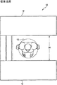
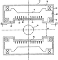
さて、図面、特に図1及び図2を参照すると、全体を符号10で示した従来技術の開放型磁石が図示されている。従来技術の開放型磁石10は、実質的に互いの鏡像になっており、その間に画像形成容積16を含む空間14を形成する1対の間隔をおいて配置されたコイル組立体12を含む。各コイル組立体12は一般的に、縦軸線20をもつ環状形状の主コイル18と、該縦軸線20に沿って同軸に位置合わせされかつ主コイル18から縦方向外側に間隔をおいて配置された環状形状の遮蔽コイル22と、主コイル18と遮蔽コイル22との間で縦軸線20の周りに配置された円柱形状の磁化可能な磁極片24とを有する。支持部材26が2つのコイル組立体12を相互結合しており、該支持部材26はステンレス鋼のような磁化不能な材料で作られている。主コイル18及び遮蔽コイル22は一般的に、超伝導性であり、従ってその臨界温度より低い温度に冷却されて、その極低温冷却によって超伝導性を達成し維持する。冷却を達成するため、開放型磁石10は更に、液体ヘリウムのような液体の極低温冷却剤を収容しかつ主コイル18及び遮蔽コイル22を囲む極低温冷却剤容器28を備える。磁極片24は、極低温冷却剤容器28の外側に該極低温冷却剤容器28から間隔をおいて配置されており、鉄のような強磁性体材料で作られる。
With reference now to the figures, and in particular with reference to FIGS. 1 and 2, a prior art open magnet, generally designated 10 is illustrated. The prior art
開放型磁石10は、超伝導型磁石に限定されるものではなく、抵抗型磁石、又は抵抗型及び超伝導型を組み合わせた磁石とすることができる。同様に主コイル18及び遮蔽コイル22も超伝導型コイルに限定されず、抵抗型コイル、又は抵抗型及び超伝導型を組み合わせたコイルとすることができる。
The
図2、図3及び図4を参照すると、間隔をおいて配置されたコイル組立体12の磁化可能な磁極片24が、主コイル18によって生成された磁界の強さを増強している。磁極片24は、強磁性体材料で作られ、互いに向かい合った内面32をもつほぼ円柱形の構成のような所望の構成にされた磁化可能な本体30を有する。磁極片24の内面32は、該内面上に形成された幾つかの環状段部34、36、38を有し、該環状段部が、開放型磁石10の磁界を成形する。上述したように、従来技術の磁石10の磁極片24において生じていた問題は、該磁極片がコイル組立体12の間の空間14内に突出しており、そのため従来技術の開放型磁石10の空間14の使用可能な容積を減少させることである。更に、段部形成技術による磁界成形能力は、主磁界が増加するにつれて減少し、そのため高磁界の開放型MRI磁石において満足できる均質な画像形成磁界を生成することができない。
With reference to FIGS. 2, 3, and 4, the
図4,5を参照すると、従来技術の磁極片24に関する上記問題点を克服した、開放型磁石10に使用される本発明の磁極片40が示されている。従来技術の磁極片24と同様に、本発明の磁極片40は、それぞれの外面44と、該外面44の方向とほぼ反対の方向を向いているそれぞれの内面46とを有し、該内面46が互いに向かい合うようになっている、円柱形状の磁化可能な本体42を有する。しかしながら、従来技術の磁極片24と異なり、本発明の磁極片40は、その内面46に凹設された複数の同心に配列され半径方向に間隔をおいて配置された環状形状の溝48と、それぞれの溝48内に挿入されて開放型磁石10の磁界を成形する、超伝導型か又は抵抗型かのいずれかの複数の環状形状のコイル50とを有する。コイル50は、それらを溝48内に挿入する前に予め巻かれ、次いで締まり嵌め54又はエポキシによる本体42との接着56によるような機械的締結要素52によって溝48内に保持されることができる。これらコイル50を流れる電流は、磁極片40の磁化を再分布させ、空間14の画像形成容積16における均質な磁界を作り出すようになる。本発明の利点には、コイル組立体12間の空間14におけるより大きい空き容積を形成すること、及び磁極片40の製造及び磁石の極低温維持構造の製造を簡素化することが含まれる。更に、製作公差による不均質性をシム調整するために、軸方向修正用のコイルを容易に磁界成形コイルと共に巻くことができる。
4 and 5, there is shown a
本発明の一部の好ましい特徴的形状のみを図示し説明したが、当業者は多くの改良及び変更を思い付くであろう。従って、同時に提出する特許請求の範囲は、全てのそのような改良及び変更を本発明の技術思想の範囲内に含まれるものと保護することを意図していることを理解されたい。 Although only some preferred features of the invention have been illustrated and described, many modifications and changes will occur to those skilled in the art. Accordingly, it is to be understood that the appended claims are intended to protect all such modifications and changes as fall within the scope of the spirit of the invention.
10 開放型磁石
14 空間
16 画像形成容積
18 主コイル
20 縦軸線
22 遮蔽コイル
28 極低温冷却剤容器
40 磁極片
42 磁極片の本体
44 磁極片の外面
46 磁極片の内面
48 内面の溝
50 コイル
DESCRIPTION OF
Claims (10)
強磁性体材料で作られ、外面と該外面の方向とほぼ反対の方向に向いている内面とを有し、前記内面が互いに向かい合い、かつ該内面の各々がその中に形成された複数のほぼ環状形状の連続する溝を有するようになっている磁化可能な本体と、
前記磁化可能な本体の内面の前記溝内において該内面のほぼ後ろ側に配置された、導電体材料で作られた複数のほぼ環状形状のコイルと、
前記磁化可能な本体の内面の前記溝内に前記コイルを保持するための手段と、
を含み、
前記磁極片は、液体の極低温冷却剤を収容する極低温冷却剤容器により囲まれる
ことを特徴とする磁極片。 A pole piece used for an open magnet,
Made ferromagnetic material, has an inner surface facing the substantially opposite direction to the direction of the outer surface and outer surface, said interior surface face one another, and a plurality of each of the inner surface is formed therein substantially A magnetizable body adapted to have an annular shaped continuous groove;
A plurality of substantially annular coils made of a conductive material disposed within the groove of the inner surface of the magnetizable body and substantially rearward of the inner surface;
Means for retaining the coil in the groove in the inner surface of the magnetizable body;
Only including,
The pole piece, wherein the pole piece is surrounded by a cryogenic coolant container containing a liquid cryogenic coolant .
を含み、該コイル組立体が、
共通の縦軸線を定め、該縦軸線に沿って互いに間隔をおいて配置された環状形状の主コイルと、
前記縦軸線に沿って同軸に位置合わせされ、互いに反対の方向に前記主コイルから縦方向外側に間隔をおいて配置された環状形状の遮蔽コイルと、
該コイル組立体のうちの1つにおける前記それぞれの主コイルと遮蔽コイルとの間で前記縦軸線の周りに各々が配置された円柱形状の磁化可能な磁極片と、
液体の極低温冷却剤を収容する極低温冷却剤容器であって、前記磁極片が、該極低温冷却剤容器により囲まれる極低温冷却剤容器と
をそれぞれ含み、該磁極片が、
強磁性体材料で作られ、それぞれの外面と該外面の方向とほぼ反対の方向に向いているそれぞれの内面とを有し、前記内面が互いに向かい合いかつ該内面の各々がその中に形成された複数の同心に配列され間隔をおいて配置された環状形状の溝を有するようになっている、磁化可能な本体と、
前記磁化可能な本体の内面の前記溝内において該内面のほぼ後ろ側に配置された、導電体材料で作られた複数の環状形状のコイルと、
前記磁化可能な本体の内面の前記溝内に前記コイルを保持するための手段と、
ことを特徴とする磁極片を含む、
ことを特徴とする開放型磁石。 A pair of coil assemblies spaced from each other to form a space therebetween,
The coil assembly comprises:
An annular main coil defining a common longitudinal axis and spaced from each other along the longitudinal axis;
An annular shielding coil that is coaxially aligned along the longitudinal axis and is spaced longitudinally outward from the main coil in opposite directions;
A cylindrical magnetizable pole piece each disposed about the longitudinal axis between the respective main coil and shield coil in one of the coil assemblies;
A cryogenic coolant container containing a liquid cryogenic coolant, the pole pieces each including a cryogenic coolant container surrounded by the cryogenic coolant container, the pole pieces comprising: ,
Made of a ferromagnetic material and having a respective outer surface and a respective inner surface facing in a direction substantially opposite to the direction of the outer surface, the inner surfaces facing each other and each of the inner surfaces being formed therein A magnetizable body adapted to have a plurality of concentrically arranged and spaced annular grooves;
A plurality of annularly shaped coils made of a conductive material disposed within the groove of the inner surface of the magnetizable body and substantially behind the inner surface;
Means for retaining the coil in the groove in the inner surface of the magnetizable body;
Including a pole piece characterized by
An open magnet characterized by that.
を含み、該コイル組立体が、
共通の縦軸線を定め、該縦軸線に沿って互いに間隔をおいて配置された環状形状の主コイルと、
前記縦軸線に沿って同軸に位置合わせされ、互いに反対の方向に前記主コイルから縦方向外側に間隔をおいて配置された環状形状の遮蔽コイルと、
該コイル組立体のうちの1つにおける前記それぞれの主コイルと遮蔽コイルとの間で前記縦軸線の周りに各々が配置された円柱形状の磁化可能な磁極片と、
液体の極低温冷却剤を収容しかつ前記主コイル及び前記遮蔽コイル及び前記磁極片を囲む極低温冷却剤容器と、
をそれぞれ含み、該磁極片が、
強磁性体材料で作られ、それぞれの外面と該外面の方向とほぼ反対の方向に向いているそれぞれの内面とを有し、前記内面が互いに向かい合いかつ該内面の各々がその中に形成された複数の同心に配列され間隔をおいて配置された環状形状の溝を有し、前記内面が更に、前記磁極片の外周部の近傍において環状段部を有しており、前記主コイルが、前記環状段部を囲んで配置されている、磁化可能な本体と、
前記磁化可能な本体の内面の前記溝内において該内面のほぼ後ろ側に配置された、導電体材料で作られた複数の環状形状のコイルと、
前記磁化可能な本体の内面の前記溝内に前記コイルを保持するための手段と、
を含み、
前記極低温冷却剤容器は、前記環状形状の溝を覆う位置において、前記環状段部よりもより前記外面方向に位置する内側面を有している
ことを特徴とする開放型磁石。
A pair of coil assemblies spaced from each other to form a space therebetween,
The coil assembly comprises:
An annular main coil defining a common longitudinal axis and spaced from each other along the longitudinal axis;
An annular shielding coil that is coaxially aligned along the longitudinal axis and is spaced longitudinally outward from the main coil in opposite directions;
A cylindrical magnetizable pole piece each disposed about the longitudinal axis between the respective main coil and shield coil in one of the coil assemblies;
A cryogenic coolant container containing a liquid cryogenic coolant and surrounding the main coil, the shielding coil and the pole piece;
Each of the pole pieces,
Made of a ferromagnetic material and having a respective outer surface and a respective inner surface facing in a direction substantially opposite to the direction of the outer surface, the inner surfaces facing each other and each of the inner surfaces being formed therein have a groove of a plurality of annular shape which are disposed at sequenced intervals concentrically, said interior surface further has an annular step in the vicinity of the outer peripheral portion of the pole piece, said main coil, said A magnetizable body disposed around an annular step ;
A plurality of annularly shaped coils made of a conductive material disposed within the groove of the inner surface of the magnetizable body and substantially behind the inner surface;
Means for retaining the coil in the groove in the inner surface of the magnetizable body;
Only including,
The open-type magnet, wherein the cryogenic coolant container has an inner surface positioned in the outer surface direction more than the annular step portion at a position covering the annular groove. .
Applications Claiming Priority (3)
| Application Number | Priority Date | Filing Date | Title |
|---|---|---|---|
| US68137101A | 2001-03-26 | 2001-03-26 | |
| US09/949,623 US6504461B2 (en) | 2001-03-26 | 2001-09-10 | Open magnet with recessed field shaping coils |
| PCT/US2002/009272 WO2002077658A1 (en) | 2001-03-26 | 2002-03-25 | Open magnet with recessed field shaping coils |
Publications (3)
| Publication Number | Publication Date |
|---|---|
| JP2004529692A JP2004529692A (en) | 2004-09-30 |
| JP2004529692A5 JP2004529692A5 (en) | 2005-12-22 |
| JP3861058B2 true JP3861058B2 (en) | 2006-12-20 |
Family
ID=27102644
Family Applications (1)
| Application Number | Title | Priority Date | Filing Date |
|---|---|---|---|
| JP2002575657A Expired - Fee Related JP3861058B2 (en) | 2001-03-26 | 2002-03-25 | Open magnet with embedded magnetic field forming coil |
Country Status (4)
| Country | Link |
|---|---|
| US (1) | US6504461B2 (en) |
| EP (1) | EP1373918A1 (en) |
| JP (1) | JP3861058B2 (en) |
| WO (1) | WO2002077658A1 (en) |
Families Citing this family (8)
| Publication number | Priority date | Publication date | Assignee | Title |
|---|---|---|---|---|
| GB2355798B (en) * | 1999-10-26 | 2004-05-19 | Oxford Magnet Tech | Improved magnetic coil former |
| US7242191B2 (en) * | 2002-11-25 | 2007-07-10 | General Electric Company | Cold mass support structure and helium vessel of actively shielded high field open MRI magnets |
| US6844801B2 (en) | 2003-03-21 | 2005-01-18 | Ge Medical Systems Global Technology Company, Llc | Methods and apparatus for adjusting center magnetic field of a magnetic field generator for MRI |
| US6859123B2 (en) * | 2003-04-03 | 2005-02-22 | Ge Medical Systems Global Technology Company, Llc | Methods and apparatus for positioning permanent magnetic blocks |
| US7001479B2 (en) | 2003-04-03 | 2006-02-21 | Ge Medical Systems Global Technology Company, Llc | Methods and apparatus for assembling magnetized permanent magnetic blocks |
| US7019525B2 (en) * | 2004-01-06 | 2006-03-28 | Ge Medical Systems Glogal Technology Company, Llc | Method and apparatus for magnetic resonance imaging |
| US7274192B2 (en) * | 2005-05-31 | 2007-09-25 | General Electric Company | Combined open and closed magnet configuration for MRI |
| KR101152835B1 (en) | 2010-12-27 | 2012-06-12 | 한국표준과학연구원 | Magnetic Field Cancellation Apparatus And Magnetic Field Cancellation Method |
Family Cites Families (11)
| Publication number | Priority date | Publication date | Assignee | Title |
|---|---|---|---|---|
| US3409806A (en) | 1964-12-15 | 1968-11-05 | Steinert Elektromagnetbau | Electromagnetic devices with great magnetomotive forces |
| DE3616078A1 (en) * | 1986-05-13 | 1987-11-19 | Bruker Analytische Messtechnik | ELECTROMAGNETIC SYSTEM FOR THE NUCLEAR MRI |
| US5402094A (en) | 1994-08-15 | 1995-03-28 | Enge; Harald A. | MRI mammography magnet |
| US5565831A (en) * | 1995-10-23 | 1996-10-15 | General Electric Company | Shielded and open MRI magnet |
| IT1294051B1 (en) | 1997-04-29 | 1999-03-15 | Esaote Spa | MAGNETIC STRUCTURE FOR THE GENERATION OF MAGNETIC FIELDS SUITABLE FOR USE IN IMAGE DETECTION IN NUCLEAR MAGNETIC RESONANCE |
| US6002255A (en) | 1997-11-20 | 1999-12-14 | Brigham & Women's Hospital | Planar open magnet MRI system having active target field shimming |
| US6011396A (en) | 1998-01-02 | 2000-01-04 | General Electric Company | Adjustable interventional magnetic resonance imaging magnet |
| US5874880A (en) | 1998-03-05 | 1999-02-23 | General Electric Company | Shielded and open superconductive magnet |
| US5883558A (en) * | 1998-02-19 | 1999-03-16 | General Electric Company | Open superconductive magnet having shielding |
| US6172588B1 (en) | 1999-04-23 | 2001-01-09 | General Electric Company | Apparatus and method for a superconductive magnet with pole piece |
| GB2355798B (en) | 1999-10-26 | 2004-05-19 | Oxford Magnet Tech | Improved magnetic coil former |
-
2001
- 2001-09-10 US US09/949,623 patent/US6504461B2/en not_active Expired - Lifetime
-
2002
- 2002-03-25 EP EP02733892A patent/EP1373918A1/en not_active Ceased
- 2002-03-25 WO PCT/US2002/009272 patent/WO2002077658A1/en active Application Filing
- 2002-03-25 JP JP2002575657A patent/JP3861058B2/en not_active Expired - Fee Related
Also Published As
| Publication number | Publication date |
|---|---|
| US6504461B2 (en) | 2003-01-07 |
| US20020135450A1 (en) | 2002-09-26 |
| WO2002077658A1 (en) | 2002-10-03 |
| JP2004529692A (en) | 2004-09-30 |
| EP1373918A1 (en) | 2004-01-02 |
Similar Documents
| Publication | Publication Date | Title |
|---|---|---|
| US5959454A (en) | Magnet arrangement for an NMR tomography system, in particular for skin and surface examinations | |
| US7071694B1 (en) | Magnet assembly of an MRI system with concentric annular ferromagnetic laminations | |
| JP3673556B2 (en) | Open magnetic resonance imaging magnet with superconducting shield | |
| US7567083B2 (en) | Superconductive magnetic apparatus for magnetic resonance imaging unit | |
| JP3631533B2 (en) | Magnetic resonance imaging magnet | |
| JPH10225447A (en) | Plane-type magnetic resonance imaging magnet | |
| JPH0838455A (en) | Flat magnetic resonance imaging magnet | |
| JP3835840B2 (en) | Magnet with contoured pole face | |
| JPH09182730A (en) | Open magnetic resonance imaging magnet | |
| US20060181381A1 (en) | Dipole shim coil for external field adjustment of a shielded superconducting magnet | |
| JP4168119B2 (en) | Magnet with a trapezoidal shim on the pole face | |
| JP3861058B2 (en) | Open magnet with embedded magnetic field forming coil | |
| JP4179578B2 (en) | Open superconducting magnet and magnetic resonance imaging system using the same | |
| JP4043946B2 (en) | Low leakage magnetic field magnet and shield coil assembly | |
| JP3583528B2 (en) | Electromagnet for use in magnetic resonance imaging equipment | |
| JP4292261B2 (en) | Magnet apparatus and MRI apparatus using the same | |
| US5384538A (en) | Magnetic field generation device for use in superconductive type MRI | |
| US20040100261A1 (en) | Cold mass support structure and helium vessel of actively shielded high field open MRI magnets | |
| JP2001078982A (en) | Open type magnet device | |
| JPS625161A (en) | Magnet for mri | |
| US6633215B2 (en) | Superconducting magnetic resonance imaging magnet assembly and method with reverse wire channel orientation | |
| WO2000033100A1 (en) | Magnetic resonance imaging system | |
| US20110241812A1 (en) | Magnetic field generator based on dual permanent magnet rings | |
| JPH10155765A (en) | Close structured magnetic resonance imaging magnet | |
| JPS62169311A (en) | Superconductive magnet device for nmar imaging |
Legal Events
| Date | Code | Title | Description |
|---|---|---|---|
| A521 | Request for written amendment filed |
Free format text: JAPANESE INTERMEDIATE CODE: A523 Effective date: 20050323 |
|
| A621 | Written request for application examination |
Free format text: JAPANESE INTERMEDIATE CODE: A621 Effective date: 20050323 |
|
| A977 | Report on retrieval |
Free format text: JAPANESE INTERMEDIATE CODE: A971007 Effective date: 20060223 |
|
| A131 | Notification of reasons for refusal |
Free format text: JAPANESE INTERMEDIATE CODE: A131 Effective date: 20060307 |
|
| A521 | Request for written amendment filed |
Free format text: JAPANESE INTERMEDIATE CODE: A523 Effective date: 20060529 |
|
| TRDD | Decision of grant or rejection written | ||
| A01 | Written decision to grant a patent or to grant a registration (utility model) |
Free format text: JAPANESE INTERMEDIATE CODE: A01 Effective date: 20060829 |
|
| A61 | First payment of annual fees (during grant procedure) |
Free format text: JAPANESE INTERMEDIATE CODE: A61 Effective date: 20060925 |
|
| R150 | Certificate of patent or registration of utility model |
Free format text: JAPANESE INTERMEDIATE CODE: R150 |
|
| FPAY | Renewal fee payment (event date is renewal date of database) |
Free format text: PAYMENT UNTIL: 20100929 Year of fee payment: 4 |
|
| FPAY | Renewal fee payment (event date is renewal date of database) |
Free format text: PAYMENT UNTIL: 20110929 Year of fee payment: 5 |
|
| FPAY | Renewal fee payment (event date is renewal date of database) |
Free format text: PAYMENT UNTIL: 20110929 Year of fee payment: 5 |
|
| FPAY | Renewal fee payment (event date is renewal date of database) |
Free format text: PAYMENT UNTIL: 20120929 Year of fee payment: 6 |
|
| FPAY | Renewal fee payment (event date is renewal date of database) |
Free format text: PAYMENT UNTIL: 20130929 Year of fee payment: 7 |
|
| R250 | Receipt of annual fees |
Free format text: JAPANESE INTERMEDIATE CODE: R250 |
|
| R250 | Receipt of annual fees |
Free format text: JAPANESE INTERMEDIATE CODE: R250 |
|
| LAPS | Cancellation because of no payment of annual fees |