JP3859082B2 - Vacuum cleaner - Google Patents
Vacuum cleaner Download PDFInfo
- Publication number
- JP3859082B2 JP3859082B2 JP2004340959A JP2004340959A JP3859082B2 JP 3859082 B2 JP3859082 B2 JP 3859082B2 JP 2004340959 A JP2004340959 A JP 2004340959A JP 2004340959 A JP2004340959 A JP 2004340959A JP 3859082 B2 JP3859082 B2 JP 3859082B2
- Authority
- JP
- Japan
- Prior art keywords
- dust
- suction port
- dust collecting
- electric blower
- vacuum cleaner
- Prior art date
- Legal status (The legal status is an assumption and is not a legal conclusion. Google has not performed a legal analysis and makes no representation as to the accuracy of the status listed.)
- Expired - Fee Related
Links
Images


Landscapes
- Filters For Electric Vacuum Cleaners (AREA)
Description
本発明は、電動送風機の駆動により吸い込まれた塵埃を捕集する集塵部を備えた電気掃除機に関する。 The present invention relates to a vacuum cleaner provided with a dust collecting unit that collects dust sucked by driving of an electric blower.
従来、この種の電気掃除機は、電動送風機を収容した掃除機本体を備えている。この掃除機本体の下部には、電動送風機の吸込側に連通する床ブラシが一体に設けられている。この床ブラシと電動送風機との間には、電動送風機の駆動により床ブラシから吸い込まれた塵埃を空気から分離して捕集する略有底円筒状の集塵部が着脱可能に設けられている。そして、この集塵部には、床ブラシの排気側に連通する吸込口と、電動送風機の吸込側に連通する排気口とがそれぞれ開口形成されている(例えば、特許文献1参照。)。
しかしながら、上述の電気掃除機では、例えば集塵部に溜まった塵埃を廃棄するために集塵部を掃除機本体から取り外して運ぶ際に、吸込口から塵埃がこぼれて床面などを汚すおそれがあるという問題がある。 However, in the above vacuum cleaner, for example, when the dust collector is removed from the vacuum cleaner body and carried in order to dispose of dust collected in the dust collector, dust may spill out from the suction port and stain the floor surface or the like. There is a problem that there is.
また、電動送風機の吸込側に連通し集塵部を着脱可能とする集塵部収容部を掃除機本体内に設ける電気掃除機もあるが、この場合には、集塵部の取り外しの際に吸込口から集塵部収容部内にこぼれた塵埃が、電動送風機を駆動させた際に電動送風機へと吸い込まれて電動送風機の使用寿命を低下させてしまうおそれもある。 There is also a vacuum cleaner that has a dust collector housing part in the vacuum cleaner body that communicates with the suction side of the electric blower so that the dust collector part can be attached and detached, but in this case, when removing the dust collector part When the electric blower is driven, dust spilled from the suction port into the dust collecting portion accommodating portion may be sucked into the electric blower and reduce the service life of the electric blower.
この結果、上述のような電気掃除機では、使い勝手が良好でないという問題点を有している。 As a result, the above-described electric vacuum cleaner has a problem that it is not easy to use.
本発明は、このような点に鑑みなされたもので、使い勝手を向上した電気掃除機を提供することを目的とする。 This invention is made | formed in view of such a point, and it aims at providing the vacuum cleaner which improved the usability.
本発明は、電動送風機の吸込側に形成された集塵部収容部に着脱可能に設けられ、電動送風機の駆動により吸い込まれた塵埃を捕集する集塵部が、集塵部本体と、この集塵部本体に設けられ、電動送風機の駆動により吸い込まれた塵埃を集塵部本体内へと吸い込む吸込口と、集塵部本体に設けられ、塵埃収容部を通過する空気を電動送風機の吸込側に排出する排気口と、付勢手段により付勢されて吸込口を閉塞する閉塞体とを備え、集塵部を集塵部収容部に取り付けた状態で、閉塞体が付勢手段の付勢力に抗して移動して吸込口を開口し、この吸込口と本体吸込口とがパッキンを介して連結されて電動送風機の吸込側に連通する風路を形成し、閉塞体および付勢手段が風路外に位置するものである。 The present invention is detachably attached to the dust collecting unit accommodating portion formed in the suction side of the electric blower, the dust collecting unit for collecting sucked dust by driving the electric blower, a dust collecting unit main body, the A suction port that is provided in the dust collector main body and sucks in the dust sucked by the drive of the electric blower into the dust collector main body, and the air that is provided in the dust collector main body and passes through the dust container is sucked into the electric blower. An exhaust port that discharges to the side and a closing body that is energized by the energizing means to close the suction port, and the closing body is attached to the dust collecting section accommodating portion with the energizing means attached to the energizing means. It moves against the force to open the suction port, and this suction port and the main body suction port are connected via a packing to form an air passage that communicates with the suction side of the electric blower. Is located outside the wind path .
本発明によれば、集塵部を集塵部収容部に対して着脱するのに伴い、吸込口が開閉されるため、集塵部を集塵部収容部から取り外した状態で、塵埃が集塵部からこぼれることを防止でき、使い勝手を向上できる。 According to the present invention, since the suction port is opened and closed as the dust collecting part is attached to and detached from the dust collecting part accommodating part, the dust is collected with the dust collecting part removed from the dust collecting part accommodating part. It is possible to prevent spilling from the dust part and improve usability.
以下、本発明の一実施の形態の電気掃除機の構成を図1ないし図5を参照して説明する。 Hereinafter, the configuration of a vacuum cleaner according to an embodiment of the present invention will be described with reference to FIGS. 1 to 5.
図1および図5において、1は掃除機本体で、この掃除機本体1は、内部に収容された電動送風機2の駆動にて生じる吸気風とともに吸い込んだ塵埃を、掃除機本体1内に着脱可能に収容された有蓋角筒状の集塵部3にて捕集する。
In FIG. 1 and FIG. 5,
また、この掃除機本体1には、外部から空気を吸引する本体吸込口4が開口されている。この本体吸込口4には、可撓性を有し湾曲可能な細長略円筒状のホース体5が連通接続されている。このホース体5の先端には、電動送風機2の複数の動作モードなどが選択可能な手元操作部6が設けられている。この手元操作部6には、掃除機本体1内の電動送風機2などを複数の駆動モードに設定する複数の設定ボタン7が設けられているとともに、掃除する際に作業者が把持する把持部8が基端側に向けて突設されている。
The vacuum cleaner
さらに、この手元操作部6の先端には、伸縮可能な細長略円筒状の延長管9が着脱可能に連通接続されている。またさらに、この延長管9の先端には、例えば室内の床面の絨毯などの上に載置させて、この絨毯上の塵埃を吸い込む吸込口体としての床ブラシ10が着脱可能に連通接続されている。
Furthermore, an elongated, substantially cylindrical extension tube 9 that can be extended and retracted is detachably connected to the distal end of the hand operation unit 6. Furthermore, the extension brush 9 is detachably connected to a
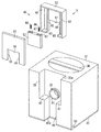
そして、掃除機本体1は、平面視で略四角形状の中空なケース本体15と、このケース本体15の前側に開口形成された開口部16と、この開口部16を開閉可能に取り付けられた蓋体17と、掃除機本体1を床面上で走行可能とする大径の走行輪18および旋回輪19とを備えている。
The
ケース本体15は、前後方向の略中心域である開口部16の若干後方の位置に、上下方向に沿って区画壁部21が形成され、この区画壁部21により、集塵部3を着脱可能に収納する集塵部収容部22と、電動送風機2を収納する電動送風機室23とを前後に区画形成している。そして、区画壁部21には、電動送風機2の吸込側と集塵部収容部22とを連通する連通孔24が格子リブ25により格子状に区画されて多数穿設されている。
The
集塵部収容部22は、図1および図3に示すように、集塵部3の外形形状に合わせた四角形状の空間部であり、上部が開口部16に連通して蓋体17により開閉可能となっている。また、この集塵部収容部22の前部には、本体吸込口4に連通する突出筒部26が後方に向けて略水平に突設されているとともに、この突出筒部26の上部には、集塵部3の前部に係合可能な押さえ板27が突設されている。また、突出筒部26の後端部には、筒部パッキン28が取り付けられている。
As shown in FIG. 1 and FIG. 3, the dust collecting
さらに、蓋体17は、前後方向に回動可能に設けられ、この回動により、開口部16を開閉するものである。そして、この蓋体17の前端部には、ケース本体15の前部の上端近傍に突設された係合部29に係合可能な係合爪部17aが設けられている。
Further, the
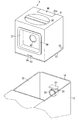
また、集塵部3は、例えば集塵部収容部22に対して上側から下側へと摺動すなわちスライドさせて取り付けるもので、図1および図2に示すように、集塵部本体としての略有蓋角筒状の集塵カップ31を有し、この集塵カップ31の前側面部には、円形状の吸込口32が開口形成されている。さらに、この集塵カップ31の下部は、底蓋33により開閉可能となっている。
The dust collecting
ここで、集塵カップ31は、例えば合成樹脂などにより形成され、図1ないし図3に示すように、前側面に形成された凹部35と、上面の前後方向中央部に形成されたハンドル36と、後側面に形成された後側凹部37とを備えている。また、集塵カップ31の内部には、吸込口32が前側に穿設され塵埃を収容する空間部である塵埃収容部41と、この塵埃収容部41と後側凹部37に穿設された排気口42とを連通する連通空間部43とが区画形成されている。
Here, the
そして、凹部35は、正面視で略四角形状に形成され、上端部が集塵カップ31の上面に連通口35aにて連通しているとともに、集塵カップ31の下面に連通する連通溝部45が下端部に連続して形成されている。さらに、この凹部35には、吸込口32が開口形成されている。そして、この凹部35には、吸込口32を開閉可能な開閉部材としての閉塞装置であるシャッタ装置46が嵌合している。
The
連通溝部45は、集塵部3を集塵部収容部22に取り付ける際に、押さえ板27および突出筒部26が嵌合する部分であり、吸込口32の下部から下方に向けて直線状に連続して形成され、集塵カップ31の下面に連通口部45aにて連通している。また、この連通溝部45は、凹部35よりも幅寸法が小さく、かつ、突出筒部26および吸込口32の幅寸法と略等しい幅寸法を有している。このため、凹部35の下端部には、連通溝部45の上部両側との間に、シャッタ装置46の下部を支持する支持段部47がそれぞれ形成されている。
The
また、シャッタ装置46は、図1および図2に示すように、前板51と、この前板51に取り付けられる後板52と、これら前板51と後板52との間に挟持される閉塞体としてのシャッタ体53とを備えている。
As shown in FIGS. 1 and 2, the
前板51は、正面視で凹部35に沿った略四角形状に形成された板体であり、上下方向の中央部よりも若干下側寄りの位置から下端部に亘って、正面視四角形状の切欠部55が切り欠き形成されている。さらに、この前板51の切欠部55の両側部には、シャッタ体53を上下方向に沿って案内すなわちガイドする一対の前部摺動ガイド56が、後方へと突設されている。これら前部摺動ガイド56は、前板51の上端部近傍から下端部近傍に亘って上下方向に直線状に連続するリブ状に形成されている。
The
また、後板52は、正面視で前板51と略等しい大きさの四角形状に形成され、下端部の中央部に切欠部55と略等しい大きさの四角形状の切欠部61が切り欠き形成されている。さらに、この後板52は、外周縁部が前側に向けて突出し前板51の後面に当接する突出枠62となっており、この突出枠62の下端部の切欠部61の両側部には、シャッタ体53の下部を支持するとともに支持段部47により支持される支持枠63が設けられている。
Further, the
そして、後板52は、切欠部61が切欠部55に対向するように前板51の後部に取り付けられ、突出枠62および支持枠63により、前板51と後板52との間にシャッタ体53を上下方向に摺動可能に収容するシャッタ収容部64が形成されている。
The
また、後板52の切欠部61の両側部には、シャッタ体53を上下方向に沿ってガイドする一対の後部摺動ガイド65が、シャッタ収容部64内にて後側から前方へと突設されている。これら後部摺動ガイド65は、後板52の上端部から下端部に亘って上下方向に直線状に連続するリブ状に形成されている。さらに、これら後部摺動ガイド65は、前部摺動ガイド56に対向している。
In addition, a pair of rear
そして、シャッタ体53は、吸込口32を開閉するものであり、切欠部55,61を閉塞可能な大きさ、かつ、切欠部55,61よりも上側のシャッタ収容部64内に収容可能な大きさの正面視四角形状に形成されている。さらに、このシャッタ体53の上側部には、このシャッタ体53を下方向に向けて付勢する付勢手段としての一対のばね66の下端部が取り付けられる取付凹部としての一対のばね受け67が形成されている。
The
なお、ばね66の上端部は、シャッタ収容部64内にて突出枠62の下端部に取り付けられている。
The upper end portion of the
また、ハンドル36は、集塵部3を持ち運び可能とするものであり、例えば集塵カップ31の左右方向に沿って設けられている。
Further, the
さらに、後側凹部37は、図1および図3に示すように、集塵カップ31の後部の略中央部に形成され、上側寄りの位置に排気口42が開口形成されている。そして、この後側凹部37の外縁部には、四角形環状の集塵部パッキン69が取り付けられている。この集塵部パッキン69は、集塵部3を集塵部収容部22に取り付けた状態で区画壁部21の前面に当接して排気口42と連通孔24とを気密に連結するものである。
Further, as shown in FIGS. 1 and 3, the rear
そして、塵埃収容部41は、電動送風機2の駆動により吸込口32から吸い込まれた空気に含まれる塵埃をサイクロン分離して集塵すなわち捕集するもので、吸込口32の上側に集塵カップ31の前後方向の中心部に向けて略水平に突設された区画リブ71により集塵カップ31内の下部に区画形成されている。また、この塵埃収容部41の下端部には、底蓋33により開閉可能な廃棄開口72が開口形成されている。さらに、この塵埃収容部41内には、区画リブ71に取り付けられたフィルタ体74が配置されている。
The
ここで、フィルタ体74は、区画リブ71の上部に載置される上部フィルタ部75と、この上部フィルタ部75に設けられた略有底円筒状のフィルタ本体76とを備えている。
Here, the
上部フィルタ部75は、略有底筒状に形成され、フィルタ本体76が挿通される突出孔77が中央部に穿設されている。そして、上部フィルタ部75には、突出孔77を覆って上部フィルタ78が取り付けられている。
The
また、フィルタ本体76は、突出孔77の周囲に係合されるフランジ部82が上端部から径方向に突設されている。さらに、このフィルタ本体76は、突出孔77に挿通され、かつ、区画リブ71の平面視の中央部に穿設され塵埃収容部41と連通空間部43とを連通する連通孔83に挿通されて塵埃収容部41内に突出している。そして、このフィルタ本体76の塵埃収容部41内に突出した部分には、側面部に複数の通気孔85が周方向に略等間隔に離間されて開口形成され、これら通気孔85のそれぞれに、メッシュ状のフィルタ86が取り付けられている。
In addition, the filter
また、連通空間部43は、区画リブ71の上部かつハンドル36の下方に区画形成されている。
In addition, the
さらに、吸込口32は、電動送風機2の駆動により吸い込まれた塵埃を集塵カップ31内へと吸い込むもので、連通溝部45の上方に位置して凹部35に開口形成され、前端部が前方に向けて円筒状に略水平に突設されている。そして、この凹部35の前端部は、シャッタ体53の後部に摺接可能となるように位置しており、その外周縁部には、集塵部3を集塵部収容部22に取り付けた状態で突出筒部26の筒部パッキン28に当接して本体吸込口4と吸込口32とを気密に連結する吸込口パッキン91が取り付けられている。
Further, the
また、底蓋33は、集塵カップ31の前部の下端部両側に回動可能に軸支された軸支部92を前端部の両側部にそれぞれ備えるとともに、集塵カップ31の後部の下端部中央に設けられた係止凹部93に係止されてこの底蓋33を集塵カップ31に係止可能な係止爪94を後端部の中央部に備えている。
In addition, the
さらに、電動送風機2は、掃除機本体1に引き出し可能に収容された図示しない電源コードを介して図示しない商用交流電源から給電されることで動作する。
Furthermore, the electric blower 2 operates by being supplied with power from a commercial AC power source (not shown) via a power cord (not shown) accommodated in the
次に、上記一実施の形態の動作を説明する。 Next, the operation of the above embodiment will be described.
まず、掃除を開始する前に、集塵部3を掃除機本体1に取り付ける。
First, before starting the cleaning, the
この取り付けに際しては、蓋体17を上方へと回動させて開口部16を開口させ、この開口部16の上部から、集塵部3を下方へと摺動させて集塵部収容部22内へと収容する。
At the time of attachment, the
このとき、図4(a)に示すように、集塵カップ31の前面を集塵部収容部22の前部に当接させつつ集塵カップ31を下方へと摺動させることで、集塵部3が下方へとガイドされ、押さえ板27がシャッタ体53の下端部に当接する。
At this time, as shown in FIG. 4 (a), the
さらに、集塵部3を下方へと摺動させると、図4(b)に示すように、ばね66の下方への付勢力に抗して押さえ板27がシャッタ体53を押し上げ、かつ、突出筒部26の筒部パッキン28が吸込口32の吸込口パッキン91に摺接する。
Further, when the
このとき、シャッタ体53は、各摺動ガイド56,65に沿ってガイドされる。
At this time, the
そして、集塵部3を集塵部収容部22内へと完全に押し込むと、図4(c)に示すように、シャッタ体53が上方へ移動して突出筒部26が吸込口32に対向して本体吸込口4が吸込口32に連通接続される。
When the
すなわち、吸込口32は、集塵部収容部22への集塵部3の取り付けに伴い開口される。
That is, the
同時に、集塵部3の後面は、集塵部パッキン69を介して区画壁部21に当接する。
At the same time, the rear surface of the
この状態で、作業者は蓋体17を下方へと回動させて開口部16を閉じ、電源コードを掃除機本体1内から引き出して図示しないコンセントへと接続し、把持部8を把持して所定の設定ボタン7を操作して電動送風機2を所定の動作モードで駆動させ、かつ、床ブラシ10を床面上で前後方向に走行させて床面の塵埃を空気とともに吸い込む。
In this state, the operator turns the
床ブラシ10から塵埃とともに吸い込まれた空気は、吸気風となり、延長管9、ホース体5、本体吸込口4および吸込口32を介して集塵カップ31の塵埃収容部41内へと流入し、この塵埃収容部41の内壁に沿ってフィルタ体74の周囲を螺旋状に旋回することで、塵埃がサイクロン分離されて塵埃収容部41内に捕集される。
The air sucked together with dust from the
塵埃がサイクロン分離された吸気風は、通気孔85および突出孔77を通過する際にフィルタ86および上部フィルタ78により微細塵が捕集された後、連通空間部43内に流入し、排気口42から集塵カップ31の外部へと排気され、連通孔24を通過して電動送風機2に吸い込まれる。
The intake air from which the dust is separated from the cyclone flows into the
さらに、電動送風機2に吸い込まれた吸気風は、電動送風機2内を通過して排気風となり、図示しない排気孔から電動送風機室23内へと排気された後、ケース本体15などに穿設された図示しない排気孔から掃除機本体1の外部へと排気される。
Further, the intake air sucked into the electric blower 2 passes through the electric blower 2 to become exhaust air, and is exhausted from an exhaust hole (not shown) into the
そして、掃除が終了すると、作業者が所定の設定ボタン7を操作して電動送風機2を停止させる。 When the cleaning is completed, the operator operates the predetermined setting button 7 to stop the electric blower 2.
また、塵埃収容部41に所定量以上の塵埃が溜まった際には、作業者は蓋体17を上方へと回動させて開口部16を開口させ、集塵部3を集塵部収容部22から取り出す。
When a predetermined amount or more of dust is accumulated in the
このとき、集塵部3のハンドル36を把持して集塵部3を上方へと引き上げることで、上記集塵部3の取り付けと逆の作用により、シャッタ体53がばね66の付勢力にて下方へと摺動し、吸込口32を閉塞する。
At this time, by grasping the
すなわち、吸込口32は、集塵部収容部22からの集塵部3の取り外しに伴い閉じられる。
That is, the
そして、作業者は、集塵部3を運んでごみ箱などの上で底蓋33の係止爪94を係止凹部93から外し、底蓋33を開けて塵埃収容部41内の塵埃を廃棄開口72から外部へと廃棄する。
Then, the operator carries the
この後、作業者は底蓋33を閉じて集塵部3を再度集塵部収容部22へと取り付けて使用する。
Thereafter, the operator closes the
上述したように、上記一実施の形態によれば、集塵部3を集塵部収容部22に対して着脱するのに伴い、吸込口32が開閉されるため、集塵部3を集塵部収容部22から取り外した状態で、塵埃が集塵部3の吸込口32からこぼれることを防止できる。
As described above, according to the above-described embodiment, the
したがって、集塵部3の着脱の際に集塵部収容部22内に塵埃がこぼれないので、集塵部収容部22内にこぼれた塵埃を電動送風機2が誤って吸い込んでしまい、電動送風機2の使用寿命が短くなることなどを防止できる。
Accordingly, dust does not spill into the dust collecting
同時に、集塵部3を掃除機本体1から取り外して塵埃収容部41に溜まった塵埃を廃棄する際などにも、集塵部3を運ぶ最中に集塵部3内の塵埃がこぼれて床面などを汚すことなどを防止できる。
At the same time, when the
この結果、電気掃除機の使い勝手を向上できる。 As a result, the usability of the vacuum cleaner can be improved.
特に、集塵部3は、吸込口32が側面に開口形成されているので、例えば集塵部の上部などに吸込口を設ける場合などと比較して塵埃がこぼれやすいので、上記のように構成することで、塵埃が集塵部3からこぼれることを確実に防止できる。
In particular, the
また、集塵部3の着脱に伴い上下方向に摺動するシャッタ装置46により吸込口32を開閉することにより、構成を簡略化できるとともに、シャッタ体53の移動方向が集塵部3の着脱方向に沿っているため、例えばシャッタ体を回動させる構成などと比較して、集塵部収容部22内にシャッタ体53を移動可能とするための余分なスペースを確保する必要がなく、電気掃除機の大型化を防止できる。
In addition, the structure can be simplified by opening and closing the
さらに、集塵部3の着脱の際に突出筒部26および押さえ板27が嵌合する連通溝部45を、集塵部3の吸込口32側である前部に設けることにより、集塵部3を集塵部収容部22に取り付ける際に、連通溝部45に突出筒部26を嵌合させることで突出筒部26と吸込口32とを容易に軸合わせできる。
Further, by providing a
なお、上記一実施の形態において、集塵部収容部22は、例えば手元操作部6に設ける構成なども可能である。
In the above embodiment, for example, the dust collecting
また、集塵部3、あるいはシャッタ装置46などの構成は、集塵部収容部22への集塵部3の取り付けに伴い吸込口32を開閉可能であれば、上記構成に限定されるものではない。
Further, the configuration of the
さらに、集塵部収容部22への集塵部3の取り付けに伴い吸込口32を開閉可能な構成としては、シャッタ装置46に代えて、例えば開閉可能な蓋が回動する構成など、他の様々な構成とすることが可能である。
Further, as the configuration capable of opening and closing the
そして、集塵部3としては、サイクロン分離するものに代えて、例えば重力、あるいは慣性などを利用して塵埃を分離するものなどでもよい。
The
また、吸込口32を設ける位置は、集塵カップ31の上部などでもよい。
Further, the position where the
さらに、上部フィルタ78に代えて、後側凹部37にフィルタを取り付ける構成、あるいはこの後側凹部37に取り付けたフィルタと上部フィルタ78とを併用する構成なども可能である。
Further, instead of the
そして、電気掃除機としては、キャニスタ型に限らず、例えば自走式の電気掃除機などでもよく、また、例えば床ブラシ10が掃除機本体1の下面に直接形成されたアップライト型、あるいはハンディ型であっても対応させて用いることができる。
The electric vacuum cleaner is not limited to the canister type, and may be, for example, a self-propelled electric vacuum cleaner, or an upright type in which the
1 掃除機本体
2 電動送風機
3 集塵部
4 本体吸込口
22 集塵部収容部
31 集塵部本体としての集塵カップ
32 吸込口
36 ハンドル
42 排気口
53 閉塞体としてのシャッタ体
66 付勢手段としてのばね
DESCRIPTION OF
22 dust-collecting portion housing part
31 Dust collection cup as dust collection body
32 Suction port
36 Handle
42 exhaust vent
53 Shutter body as a closing body
66 Spring as biasing means
Claims (2)
前記電動送風機の吸込側に形成された集塵部収容部と、
この集塵部収容部に着脱可能に設けられ、前記電動送風機の駆動により吸い込まれた塵埃を捕集する集塵部とを具備し、
前記集塵部は、
塵埃収容部を区画形成した合成樹脂製の集塵部本体と、
この集塵部本体に設けられ、前記電動送風機の駆動により空気とともに吸い込まれた塵埃を前記塵埃収容部内へと吸い込む吸込口と、
前記集塵部本体に設けられ、前記塵埃収容部を通過する空気を前記電動送風機の吸込側に排出する排気口と、
付勢手段により付勢されて前記吸込口を閉塞する閉塞体とを備え、
前記集塵部を前記集塵部収容部に取り付けた状態で、前記閉塞体が前記付勢手段の付勢力に抗して移動して前記吸込口を開口し、この吸込口と前記本体吸込口とがパッキンを介して連結されて前記電動送風機の吸込側に連通する風路を形成し、前記閉塞体および前記付勢手段が前記風路外に位置する
ことを特徴とした電気掃除機。 A vacuum cleaner body that houses an electric blower and has a main body suction port opened;
A dust collecting portion accommodating portion formed in the suction side of the electric blower,
A dust collecting section that is detachably provided in the dust collecting section housing section and collects dust sucked in by driving of the electric blower;
The dust collecting part is
A dust collector body made of synthetic resin in which a dust container is defined;
Provided in the dust collecting unit main body, a suction port for sucking dust sucked together with air into the dust containing section by driving the electric blower,
An exhaust port that is provided in the dust collector main body and exhausts air passing through the dust container to the suction side of the electric blower;
A closing body that is biased by the biasing means and closes the suction port ;
With the dust collection part attached to the dust collection part accommodating part, the closing body moves against the urging force of the urging means to open the suction port, and the suction port and the main body suction port Are connected via a packing to form an air passage communicating with the suction side of the electric blower, and the closing body and the urging means are located outside the air passage .
吸込口は、前記集塵部本体の側面に形成されている
ことを特徴とした請求項1記載の電気掃除機。 Provided with a handle provided on the upper surface of the dust collector body,
Suction port, an electric vacuum cleaner according to claim 1 wherein characterized in that formed on the side surface of the dust collection body.
Priority Applications (1)
| Application Number | Priority Date | Filing Date | Title |
|---|---|---|---|
| JP2004340959A JP3859082B2 (en) | 2004-11-25 | 2004-11-25 | Vacuum cleaner |
Applications Claiming Priority (1)
| Application Number | Priority Date | Filing Date | Title |
|---|---|---|---|
| JP2004340959A JP3859082B2 (en) | 2004-11-25 | 2004-11-25 | Vacuum cleaner |
Publications (3)
| Publication Number | Publication Date |
|---|---|
| JP2006149456A JP2006149456A (en) | 2006-06-15 |
| JP2006149456A5 JP2006149456A5 (en) | 2006-07-27 |
| JP3859082B2 true JP3859082B2 (en) | 2006-12-20 |
Family
ID=36628440
Family Applications (1)
| Application Number | Title | Priority Date | Filing Date |
|---|---|---|---|
| JP2004340959A Expired - Fee Related JP3859082B2 (en) | 2004-11-25 | 2004-11-25 | Vacuum cleaner |
Country Status (1)
| Country | Link |
|---|---|
| JP (1) | JP3859082B2 (en) |
Cited By (1)
| Publication number | Priority date | Publication date | Assignee | Title |
|---|---|---|---|---|
| JP2011004889A (en) * | 2009-06-24 | 2011-01-13 | Hitachi Appliances Inc | Vacuum cleaner |
Families Citing this family (3)
| Publication number | Priority date | Publication date | Assignee | Title |
|---|---|---|---|---|
| KR101436630B1 (en) * | 2007-11-14 | 2014-09-01 | 엘지전자 주식회사 | Vacuum cleaner |
| CA2695815A1 (en) * | 2007-08-06 | 2009-02-12 | Dovia International Limited | Surface debris removal apparatus |
| JP2017086188A (en) * | 2015-11-04 | 2017-05-25 | 三菱電機株式会社 | Cyclone separation device and vacuum cleaner using the same |
-
2004
- 2004-11-25 JP JP2004340959A patent/JP3859082B2/en not_active Expired - Fee Related
Cited By (1)
| Publication number | Priority date | Publication date | Assignee | Title |
|---|---|---|---|---|
| JP2011004889A (en) * | 2009-06-24 | 2011-01-13 | Hitachi Appliances Inc | Vacuum cleaner |
Also Published As
| Publication number | Publication date |
|---|---|
| JP2006149456A (en) | 2006-06-15 |
Similar Documents
| Publication | Publication Date | Title |
|---|---|---|
| JP4205466B2 (en) | Electric vacuum cleaner | |
| JP4738064B2 (en) | Vacuum cleaner | |
| JP6270422B2 (en) | Electric vacuum cleaner | |
| JP3859082B2 (en) | Vacuum cleaner | |
| JP6430112B2 (en) | Electric vacuum cleaner | |
| JP5911230B2 (en) | Electric vacuum cleaner | |
| JP2006346281A (en) | Electric cleaner and its dust collecting device | |
| JP4738063B2 (en) | Vacuum cleaner | |
| JP6271220B2 (en) | Electric vacuum cleaner | |
| JP4664741B2 (en) | Vacuum cleaner and dust collector | |
| JP5860697B2 (en) | Electric vacuum cleaner | |
| JP2009201568A (en) | Vacuum cleaner | |
| JP3940052B2 (en) | Vacuum cleaner and method for cleaning a vacuum cleaner | |
| JP2007313057A (en) | Vacuum cleaner | |
| JP4664744B2 (en) | Electric vacuum cleaner | |
| JP2006334220A (en) | Electric cleaner and its dust collecting device | |
| JP2010148697A (en) | Vacuum cleaner | |
| JP2006346278A (en) | Vacuum cleaner | |
| JP4255125B2 (en) | Electric vacuum cleaner | |
| JP2007068749A (en) | Electric vacuum cleaner | |
| JP5801131B2 (en) | Electric vacuum cleaner | |
| JP2013027547A (en) | Vacuum cleaner | |
| JP5818558B2 (en) | Electric vacuum cleaner | |
| JP2007061437A (en) | Dust collector for vacuum cleaner and vacuum cleaner | |
| JP2010035623A (en) | Vacuum cleaner |
Legal Events
| Date | Code | Title | Description |
|---|---|---|---|
| A521 | Written amendment |
Free format text: JAPANESE INTERMEDIATE CODE: A523 Effective date: 20060530 |
|
| A621 | Written request for application examination |
Free format text: JAPANESE INTERMEDIATE CODE: A621 Effective date: 20060530 |
|
| A871 | Explanation of circumstances concerning accelerated examination |
Free format text: JAPANESE INTERMEDIATE CODE: A871 Effective date: 20060530 |
|
| A131 | Notification of reasons for refusal |
Free format text: JAPANESE INTERMEDIATE CODE: A131 Effective date: 20060628 |
|
| A521 | Written amendment |
Free format text: JAPANESE INTERMEDIATE CODE: A523 Effective date: 20060821 |
|
| TRDD | Decision of grant or rejection written | ||
| A01 | Written decision to grant a patent or to grant a registration (utility model) |
Free format text: JAPANESE INTERMEDIATE CODE: A01 Effective date: 20060913 |
|
| A61 | First payment of annual fees (during grant procedure) |
Free format text: JAPANESE INTERMEDIATE CODE: A61 Effective date: 20060913 |
|
| R150 | Certificate of patent or registration of utility model |
Ref document number: 3859082 Country of ref document: JP Free format text: JAPANESE INTERMEDIATE CODE: R150 Free format text: JAPANESE INTERMEDIATE CODE: R150 |
|
| A975 | Report on accelerated examination |
Free format text: JAPANESE INTERMEDIATE CODE: A971005 Effective date: 20060621 |
|
| FPAY | Renewal fee payment (event date is renewal date of database) |
Free format text: PAYMENT UNTIL: 20090929 Year of fee payment: 3 |
|
| S111 | Request for change of ownership or part of ownership |
Free format text: JAPANESE INTERMEDIATE CODE: R313113 |
|
| FPAY | Renewal fee payment (event date is renewal date of database) |
Free format text: PAYMENT UNTIL: 20090929 Year of fee payment: 3 |
|
| R350 | Written notification of registration of transfer |
Free format text: JAPANESE INTERMEDIATE CODE: R350 |
|
| FPAY | Renewal fee payment (event date is renewal date of database) |
Free format text: PAYMENT UNTIL: 20090929 Year of fee payment: 3 |
|
| S533 | Written request for registration of change of name |
Free format text: JAPANESE INTERMEDIATE CODE: R313533 |
|
| FPAY | Renewal fee payment (event date is renewal date of database) |
Free format text: PAYMENT UNTIL: 20090929 Year of fee payment: 3 |
|
| R360 | Written notification for declining of transfer of rights |
Free format text: JAPANESE INTERMEDIATE CODE: R360 |
|
| FPAY | Renewal fee payment (event date is renewal date of database) |
Free format text: PAYMENT UNTIL: 20090929 Year of fee payment: 3 |
|
| R360 | Written notification for declining of transfer of rights |
Free format text: JAPANESE INTERMEDIATE CODE: R360 |
|
| R371 | Transfer withdrawn |
Free format text: JAPANESE INTERMEDIATE CODE: R371 |
|
| S531 | Written request for registration of change of domicile |
Free format text: JAPANESE INTERMEDIATE CODE: R313531 |
|
| S533 | Written request for registration of change of name |
Free format text: JAPANESE INTERMEDIATE CODE: R313533 |
|
| FPAY | Renewal fee payment (event date is renewal date of database) |
Free format text: PAYMENT UNTIL: 20090929 Year of fee payment: 3 |
|
| R350 | Written notification of registration of transfer |
Free format text: JAPANESE INTERMEDIATE CODE: R350 |
|
| FPAY | Renewal fee payment (event date is renewal date of database) |
Free format text: PAYMENT UNTIL: 20090929 Year of fee payment: 3 |
|
| FPAY | Renewal fee payment (event date is renewal date of database) |
Free format text: PAYMENT UNTIL: 20100929 Year of fee payment: 4 |
|
| FPAY | Renewal fee payment (event date is renewal date of database) |
Free format text: PAYMENT UNTIL: 20100929 Year of fee payment: 4 |
|
| FPAY | Renewal fee payment (event date is renewal date of database) |
Free format text: PAYMENT UNTIL: 20110929 Year of fee payment: 5 |
|
| FPAY | Renewal fee payment (event date is renewal date of database) |
Free format text: PAYMENT UNTIL: 20120929 Year of fee payment: 6 |
|
| FPAY | Renewal fee payment (event date is renewal date of database) |
Free format text: PAYMENT UNTIL: 20120929 Year of fee payment: 6 |
|
| FPAY | Renewal fee payment (event date is renewal date of database) |
Free format text: PAYMENT UNTIL: 20130929 Year of fee payment: 7 |
|
| S531 | Written request for registration of change of domicile |
Free format text: JAPANESE INTERMEDIATE CODE: R313531 |
|
| S533 | Written request for registration of change of name |
Free format text: JAPANESE INTERMEDIATE CODE: R313533 |
|
| R350 | Written notification of registration of transfer |
Free format text: JAPANESE INTERMEDIATE CODE: R350 |
|
| S111 | Request for change of ownership or part of ownership |
Free format text: JAPANESE INTERMEDIATE CODE: R313115 Free format text: JAPANESE INTERMEDIATE CODE: R313117 |
|
| R371 | Transfer withdrawn |
Free format text: JAPANESE INTERMEDIATE CODE: R371 |
|
| R350 | Written notification of registration of transfer |
Free format text: JAPANESE INTERMEDIATE CODE: R350 |
|
| S111 | Request for change of ownership or part of ownership |
Free format text: JAPANESE INTERMEDIATE CODE: R313117 |
|
| S531 | Written request for registration of change of domicile |
Free format text: JAPANESE INTERMEDIATE CODE: R313531 |
|
| R350 | Written notification of registration of transfer |
Free format text: JAPANESE INTERMEDIATE CODE: R350 |
|
| LAPS | Cancellation because of no payment of annual fees |