JP3854320B2 - Photo-curing modeling equipment - Google Patents
Photo-curing modeling equipment Download PDFInfo
- Publication number
- JP3854320B2 JP3854320B2 JP15587495A JP15587495A JP3854320B2 JP 3854320 B2 JP3854320 B2 JP 3854320B2 JP 15587495 A JP15587495 A JP 15587495A JP 15587495 A JP15587495 A JP 15587495A JP 3854320 B2 JP3854320 B2 JP 3854320B2
- Authority
- JP
- Japan
- Prior art keywords
- light
- optical
- photo
- curing
- modeling apparatus
- Prior art date
- Legal status (The legal status is an assumption and is not a legal conclusion. Google has not performed a legal analysis and makes no representation as to the accuracy of the status listed.)
- Expired - Fee Related
Links
Images


Description
【0001】
【産業上の利用分野】
この発明は、光線が通過する状態と光線が遮断される状態とを切り替える光シャッタリング装置を備えた光硬化造形装置に関する。
【0002】
【従来の技術】
光硬化造形装置では、レーザ光等の光線が通過する状態と遮断される状態とを高速で切り替える光シャッタリング装置が必要となる。従来の光シャッタリング装置の一例を、図4を参照して説明する。図4は、従来の光シャッタリング装置の構成を示す平面図である。図4に示されるように、従来の光シャッタリング装置52では、レーザ光源54から出射されたレーザ光ビーム56を音響光学式光変調器(Acousto-Optic Modulator ,以下「AOM」と略する)モジュール60に入射させる。AOMモジュール60では、所定の周波数の超音波が印加されることによって、レーザ光ビーム56の偏向が行われる。すなわち、超音波が印加されていない状態では、レーザ光ビーム56は直進する0次光56Bとして出射する。また、超音波が印加された状態では、レーザ光ビーム56は角度θだけ偏向した1次光56Aとなって出射する。このうち、0次光56Bはスリット72によって遮断され、偏向した1次光56Aのみがスリット72の開口部72aを通過する。従って、AOMモジュール60に超音波を印加した状態と印加しない状態とを高速で切り替えることによって、レーザ光56が通過する状態と遮断される状態とを高速で切り替えることができる。
【0003】
【発明が解決しようとする課題】
しかしながら、このようなAOMモジュール60等の高速光偏向器による偏向角は極めて小さい。図4においては見易くするため偏向角θを実際よりずっと大きく描いているが、AOMモジュール60による偏向角θは、実際には4.24mrad(約0.25°)程度と極めて小さいものである。従って、0次光56Bと1次光56Aとをスリット72で完全に分離するためには、AOMモジュール60からスリット72までの距離L10は1m近くもの長さをとる必要がある。このため、光シャッタリング装置52の全長が長くなって、光シャッタリング装置を備えている光硬化造形装置の小型化を妨げる。また、このように光路が長くなることによって、光源,レンズ,ミラー等における光収差の影響も拡大され、光ビームの最小集光径が大きくなってしまう。さらに、光源の温度変化等に起因する光軸のずれも光路が長くなることによって増幅され、光硬化造形装置で造形する立体モデルの精度を劣化させるという問題点があった。
【0004】
そこで、本発明においては、光路を短くして装置を小型化することができる光硬化造形装置を提供することを目的とする。また、本発明においては、かかる目的を容易かつ確実に達成することができ、かつ、光硬化造形装置に必要とされる最小集光点の深さを変える光学系と光シャッタリング装置が複合している光硬化造形装置を提供する。
【0005】
【課題を解決するための手段】
請求項1に係る発明は、光線を射出する光源と、その光線が通過する状態と遮断される状態とを切り替える光シャッタリング装置と、その光線を反射して進行方向を変えるガルバノミラーと、光硬化性液状樹脂を収容しておく容器を備えている光硬化造形装置に関する。この光硬化造形装置では、ガルバノミラーによって、光線のスポットを容器内に収容されている光硬化性液状樹脂の液面内の任意の位置に向けることができるとともに、光シャッタリング装置によって、容器内に収容されている光硬化性液状樹脂の液面内の位置に応じて、光線のスポットを照射するかしないかを切り替えることができる。すなわち、液面内の任意の位置を光線のスポットで照射することができるとともに、照射しないこともできる。
その光シャッタリング装置は、光線の進行方向を変化させる光偏向器と、該光偏向器から出射した光線を集光する集光レンズと、その集光レンズの焦点面に設けられた空間フィルタを有することを特徴とする。ここで、集光レンズの焦点面とは、集光レンズの焦点を含み、集光レンズの光軸に垂直な面をいう。
【0006】
また、本発明の光硬化造形装置は、前記集光レンズにビームエクスパンダを構成する集光レンズを用いることを特徴とする。
また、空間フィルタの後方に、第2の集光レンズが配置されていることを特徴とする。すなわち、空間フィルタの前後に一対の集光レンズが配置されていることを特徴とする。一対の集光レンズは、ビームエクスパンダを構成する。空間フィルタの前方に配置されている第1の集光レンズは、光シャッタリング装置とビームエクスパンダの構成部材を兼用している。
本発明の光硬化造形装置は、ビームエクスパンダを構成する第2の集光レンズ(空間フィルタの後方に配置されている集光レンズ)が、光線の光軸に沿って移動可能なことを特徴とする。
【0007】
【作用】
さて、請求項1に係る光硬化造形装置は、光線が通過する状態と遮断される状態とを切り替える光シャッタリング装置を備えており、その光シャッタリング装置が、光線の進行方向を変化させる光偏向器と、光偏向器から出射した光線を集光する集光レンズと、集光レンズの焦点面に設けられた空間フィルタとを有している。光偏向器から出射した光線は集光レンズに入射し、集光レンズの焦点面上に集光される。ここで、光偏向器から出射した光線が偏向されていない場合と偏向されている(進行方向が変化させられている)場合とでは、集光レンズによって集光される位置が異なる。すなわち、集光レンズはフーリエ変換レンズとして機能し、偏向されていない光線と偏向された光線のフーリエ変換像が、互いに空間周波数の異なる点に結像されると考えることができる。従って、集光レンズの焦点面に置かれた空間フィルタによって、これらのフーリエ変換像のうちいずれかの成分のみを遮断し、他の成分を通過させることが可能となる。すなわち、偏向されていない光線と偏向された光線のうち一方を遮断して、他方を通過させることができる。この結果、光偏向器で光線が偏向されていない状態と偏向された状態とを切り替えることによって、光線が通過する状態と光線が遮断される状態とを切り替えることができる。
【0008】
この光シャッタリング装置では、光線が偏向されているかいないかによって集光レンズによるフーリエ変換像が互いに空間周波数の異なる点に結像されることを利用している。このため、互いの光線が分離されている必要はなく、僅かな偏向角の差異があれば、空間フィルタによって一方の光線のみを遮断することができる。従って、光偏向器の直後に集光レンズ及び空間フィルタを配置しても光シャッタリングを行うことができる。この結果、従来の装置に比較して光シャッタリング装置内の光路を著しく短くすることができ、装置を小型化することが可能となる。このようにして、光硬化造形装置を小型化することができる。
【0009】
また、本発明の光硬化造形装置では、上記の第1の集光レンズに、ビームエクスパンダを構成する集光レンズを用いている。このビームエクスパンダには、集光レンズとコリメートレンズを組み合わせて構成したものが用いられる。かかるビームエクスパンダを用いた光学機器において、ビームエクスパンダの前に光偏向器を配置し、ビームエクスパンダを構成する第1の集光レンズの焦点面に空間フィルタを配置することによって、上述の如くにして光シャッタリングを行うことができる。これによって、光学機器における光学要素の追加を極力少なくしつつ、光シャッタリング装置内の光路を著しく短くすることができ、光硬化造形装置を小型化することが可能となる。
さらに、本発明の光硬化造形装置では、空間フィルタの前方に配置されている第1の集光レンズが、光シャッタリング装置とビームエクスパンダの構成部材を兼用している。光学要素の数を少なく抑えることができる。
本発明の光硬化造形装置では、ビームエクスパンダを構成する第2の集光レンズを光軸に沿って移動させることができるために、光線の最小集光点を、液面に対して上下方向に調整することができ、液状樹脂の硬化深さを変化させることができる。
【0010】
【実施例】
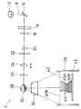
次に、本発明を具現化した一実施例について、図1乃至図3を参照して説明する。まず、本実施例の光シャッタリング装置を用いた光硬化造形装置の構成及び各部の機能について、図1及び図2を参照して説明する。光硬化造形装置とは、液状の光硬化性樹脂(以下、「液状樹脂」とも略する。)にレーザ光等の強力な光線を照射してその一部を硬化させ、任意の三次元形状を造形する装置である。この光硬化造形装置は、CADシステムで設計した機械部品等をCADデータを用いて容易に実体化することができ、設計の確認と直接的な評価を行える。また、近年の多品種少量生産の要請にも適合した極めて有用な装置である。図1は本実施例の光シャッタリング装置を用いた光硬化造形装置の構成を示す平面図であり、図2はその正面図である。なお、図1及び図2は、光硬化造形装置の中心となる光学系の構成のみを示しており、ミラー,レンズ等の支持機構や駆動機構等は省略されている。
【0011】
図1に示されるように、本実施例における光硬化造形装置2はレーザ光源として He-Cdレーザ4を有している。この He-Cdレーザ4から出射される紫外線レーザ光6が全反射ミラー8で反射され、AOMモジュール10に入射される。AOMモジュール10に入射した紫外線レーザ光6は、直進する0次光または僅かに偏向した1次光として出射して、全反射ミラー12で真下方向(図1の紙面に垂直な方向)に反射され、さらに全反射ミラー14で水平方向に反射される。
従って、このAOMモジュール10は、本発明における光偏向器として機能する。また、AOMモジュール10は、後述する液状樹脂40に照射される紫外線レーザ光6の強度を変化させる機能をも有する。
すなわち、AOMモジュール10に印加される超音波の電力を変化させることによって、0次光と1次光との強度比率が変化する。後述するように、最終的に液状樹脂40に照射されるのは紫外線レーザ光6の1次光のみであるため、0次光と1次光との強度比率を変えることによって、液状樹脂40に照射される紫外線レーザ光6の強度が変わることになる。
【0012】
続いて、紫外線レーザ光6はメカシャッター16及び虹彩絞り18を通過して、ビームエクスパンダを構成する凸レンズ20に入射する。この凸レンズ20と凸レンズ24とによって、紫外線レーザ光6のビーム径を拡大するためのビームエクスパンダが構成されている。
凸レンズ20と凸レンズ24との間には、空間フィルター22が設けられている。この空間フィルター22は凸レンズ20の焦点に位置しており、本実施例においては空間フィルター22としてスリットを用いている。
前述のAOMモジュール10と、これらの凸レンズ20及び空間フィルター22によって、本実施例の光シャッタリング装置1が構成されている。
【0013】
この光シャッタリング装置1による光シャッタリングの機構について、図3を参照して説明する。図3は、本実施例の光シャッタリング装置1の主要部分の構成を示す平面図である。
図1に示されるAOMモジュール10から出射した0次光レーザビーム6B及び1次光レーザビーム6Aは、図3の右方から凸レンズ20に入射する。ここで、凸レンズ20は、その光軸が1次光6Aの光路と一致するように設置されている。従って、0次光6Bは凸レンズ20の光軸に対して偏向角をもって入射することになる。
凸レンズ20の光軸に沿って入射する1次光6Aは、凸レンズ20の光軸上の点6Cに集光される。一方、凸レンズ20の光軸に対して偏向角を有する0次光6Bは、点6Cから離れた点6Dに集光される。すなわち、凸レンズ20はフーリエ変換レンズとして機能し、1次光6A及び0次光6Bのフーリエ変換像が空間周波数の異なる点6C及び点6Dに結像されると考えることができる。
【0014】
従って、空間フィルターとしてのスリット22によって、これらのフーリエ変換像のうち空間周波数の異なる点6Dの成分(0次光6B)のみを遮断することができる。一方、点6Cに集光された1次光6Aは、スリット22の開口部22aを通過して、二つ目の凸レンズ24に入射する。そして、ビーム径が拡大された平行光6Eとして出射する。
このようにして、AOMモジュール10から出射したレーザ光のうち0次光6Bは空間フィルター22によって遮られ、1次光6Aのみが空間フィルター22を通過する。従って、AOMモジュール10で紫外線レーザ光6を0次光6Bと1次光6Aとに高速で切り換えることによって、ガルバノミラー28,30の走査速度に対応した高速での紫外線レーザ光6のシャッタリングが可能になる。
これによって、紫外線レーザ光6を高速で走査しながら、液状樹脂40のうち必要な部分にのみ照射することができる。
【0015】
なお、本実施例においては支持機構等の関係から、図1に示されるように、AOMモジュール10と凸レンズ20の間に全反射ミラー12,14,メカシャッター16及び虹彩絞り18が配置されており、AOMモジュール10と凸レンズ20とが離れている。
しかし、空間フィルター22を用いた光シャッタリングのためには、従来の光シャッタリング装置52におけるように0次光の光路と1次光の光路とが分離されている必要はなく、両者の間に僅かな偏向角が存在すれば良い。従って、AOMモジュール10と凸レンズ20を離す必要はなく、AOMモジュール10の直後に凸レンズ20及び空間フィルター22を配置しても、同様に機能する光シャッタリング装置を構成することができる。
これによって、光シャッタリング装置としては、従来の光シャッタリング装置52に比較して、極めて光路長の短い装置とすることができる。
【0016】
さて、図1,図2に示されるように、凸レンズ24は、紫外線レーザ光6の光軸方向に沿って移動可能となっている。この凸レンズ24の移動機構は、凸レンズ24のレンズホルダーをパルスモータを用いたスライドステージ(いずれも図示省略)に取り付けることによって構成されている。
かかる移動機構で凸レンズ24を移動させることによって、紫外線レーザ光6の最小集光点が液状樹脂40の液面から上下にずれ、この結果液状樹脂40の液面における紫外線レーザ光6のスポット径が変化する。これによって、紫外線レーザ光6による液状樹脂40の硬化径を変えることなく液状樹脂40の硬化深さを変化させることができる。
【0017】
凸レンズ24から出射したビーム径が拡大された紫外線レーザ光6は、二つ目の虹彩絞り26を通過して、ガルバノミラー28及び30によって反射される。ガルバノミラー28は、図1の紙面に垂直な回転軸を中心として回転し、ガルバノミラー30は、図1の紙面内にある回転軸を中心として回転する。これによって、図2に破線で示されるように、紫外線レーザ光6は、ガルバノミラー30の下方に設けられた樹脂容器38の全面にわたって走査される。
また、図2に示されるように、ガルバノミラー30と樹脂容器38の間には、fθレンズ32が設けられている。このfθレンズ32は、数枚のレンズが組み合わされて構成されており、紫外線レーザ光6を樹脂容器38内の液状樹脂40の表面において、全面にわたって均一なスポット径で集光する。
なお、二つの虹彩絞り18,26は、光硬化造形装置2を組み立てる際に紫外線レーザ光6の光軸合わせをするためにのみ用いられるものであり、光軸合わせが完了した後は全開とされる。また、メカシャッター16は樹脂容器38の周辺で作業をする場合等に作業者の安全のために閉じられるものであり、光硬化造形装置2の使用時には全開とされている。
【0018】
さて、かかる構成を有する本実施例の光硬化造形装置2を用いた光硬化造形の手順について、図2を参照して説明する。
図2に示されるように、光硬化造形装置2においては、液状樹脂40で満たされた容器38の中に、図示しない昇降機構によって昇降可能な昇降テーブル42が設けられている。図のような製品44を造形するには、まず、昇降テーブル42を、液状樹脂40の液面40aから製品44の最下層44aの厚さ分だけ下降した高さに位置させる。この状態で、ガルバノミラー28,30を回転させることによってレーザ光6を液状樹脂40の全面にわたって走査しつつ、必要な範囲内のみレーザ光6を照射させる。すなわち、製品44の範囲内ではAOMモジュール10によって紫外線レーザ光6を1次光6Aに切り替えて、スリット22を通過させて液状樹脂40に照射させる。それ以外の範囲では、AOMモジュール10で紫外線レーザ光6を0次光6Bに切り替えてスリット22によって遮断し、液状樹脂40が光硬化しないようにする。
このようにして、まず最下層44aを光硬化させる。次に昇降テーブル42を最下層から二番目の層44bの厚さ分だけ下降させ、同様にして二番目の層44bを光硬化させる。以下、同様にして、下から順に一層ずつ光硬化させることによって、図2に示されるような製品44が造形される。
【0019】
本実施例においては、本発明の光シャッタリング装置を光硬化造形装置に応用した例について説明したが、本発明の光シャッタリング装置はこれ以外の種々の光学装置にも応用することができる。また、光線として He-Cdレーザ4から出射される紫外線レーザ光6に対して適用しているが、Arレーザ等の他の紫外線レーザ光や、他の波長のレーザ光、さらにはレーザ光以外の光線にも適用することが可能である。
また、本実施例においては、光偏向器としてAOMモジュールを用いているが、EOM(Electro-Optic Modulator ,電気光学式光変調器)モジュールを始めとするその他の光偏向器を用いても良い。
さらに、本実施例では、空間フィルター22としてスリットを用いているが、ピンホールやガラス板上にマスクパターンを描いたもの等を空間フィルターとして用いても良い。
光シャッタリング装置のその他の部分の構成,機能,数,大きさ,接続関係等についても、本実施例に限定されるものではない。
【0020】
【発明の効果】
請求項1に係る発明では、光偏向器と集光レンズと空間フィルタを組み合わせて構成した光シャッタリング装置を利用する光硬化造形装置を創出したために、従来の光硬化造形装置に比較して光シャッタリング装置内の光路を著しく短くすることができ、光硬化造形装置を小型化することが可能となる。これによって、光収差や光軸のずれの影響を最小限に抑えて光硬化造形装置で造形する立体モデルの精度を向上させることができる。
【0021】
また、請求項2に係る発明においては、ビームエクスパンダを構成する前側の集光レンズの前後に光偏向器と空間フィルタを配置した光シャッタリング装置を創出したために、光学要素の追加を極力少なくしつつ、光シャッタリング装置内の光路を著しく短くすることができ、光硬化造形装置を小型化できる。
また、請求項3に係る光硬化造形装置では、空間フィルタの前方に配置されている集光レンズが、光シャッタリング装置とビームエクスパンダの構成部材を兼用している。光学要素の数を少なく抑えることができる。
さらに、請求項4に係る光硬化造形装置では、光線の最小集光点を、液面に対して上下方向に調整することができ、液状樹脂の硬化深さを変化させることができる。
【図面の簡単な説明】
【図1】本発明に係る光シャッタリング装置の一実施例を応用した光硬化造形装置の構成を示す平面図である。
【図2】光シャッタリング装置の一実施例を応用した光硬化造形装置の構成を示す正面図である。
【図3】光シャッタリング装置の一実施例の主要部分の構成を示す平面図である。
【図4】従来例の光シャッタリング装置の構成を示す平面図である。
【符号の説明】
1 光シャッタリング装置
6 光線
10 光偏向器
20 集光レンズ
22 空間フィルタ[0001]
[Industrial application fields]
The present invention relates to a photo-curing modeling apparatus including an optical shuttering device that switches between a state in which a light beam passes and a state in which the light beam is blocked.
[0002]
[Prior art]
In the photo- curing modeling apparatus , an optical shuttering apparatus that switches between a state where a light beam such as a laser beam passes and a state where it is blocked is required at high speed. An example of a conventional optical shuttering device will be described with reference to FIG. FIG. 4 is a plan view showing a configuration of a conventional optical shuttering device. As shown in FIG. 4, in the conventional
[0003]
[Problems to be solved by the invention]
However, the deflection angle by such a high-speed optical deflector such as the
[0004]
Therefore, in this onset bright, and an object thereof is to provide a photocurable molding apparatus the device by shortening the optical path can be miniaturized. Further, in this onset bright, the above object can be accomplished easily and reliably, and the optical system changes the depth of the minimum focal point that is required for photocuring shaping apparatus and optical shuttering device composite An optical curing modeling apparatus is provided.
[0005]
[Means for Solving the Problems]
請 Motomeko inventions according to 1, galvanometer mirror for changing a light source for emitting a light beam, a light shuttering device for switching between the state of being shut off in a state in which the light beam passes through, the traveling direction by reflecting the light beam And a photo-curing modeling apparatus including a container for storing a photo-curable liquid resin. In this photo-curing modeling apparatus, the spot of the light beam can be directed to an arbitrary position within the liquid surface of the photo-curable liquid resin contained in the container by the galvano mirror, and the light shuttering apparatus Depending on the position in the liquid surface of the photocurable liquid resin accommodated in the liquid crystal, it is possible to switch whether or not to irradiate the spot of light. That is, it is possible to irradiate an arbitrary position in the liquid surface with a light beam spot and not to irradiate it.
The light shuttering device includes an optical deflector for changing the traveling direction of the light beam, a condenser lens for the light beam emitted from the light deflector for focusing, a spatial filter provided in the focal plane of the condenser lens it characterized in that it has. Here, the focal plane of the condenser lens means a plane that includes the focal point of the condenser lens and is perpendicular to the optical axis of the condenser lens.
[0006]
Moreover, the photocuring modeling apparatus of the present invention is characterized in that a condensing lens constituting a beam expander is used for the condensing lens.
In addition, a second condenser lens is disposed behind the spatial filter. That is, a pair of condensing lenses are arranged before and after the spatial filter. The pair of condensing lenses constitutes a beam expander. The 1st condensing lens arrange | positioned ahead of a spatial filter serves as the structural member of an optical shuttering apparatus and a beam expander.
The photo-curing modeling apparatus of the present invention is characterized in that the second condensing lens (the condensing lens arranged behind the spatial filter) constituting the beam expander is movable along the optical axis of the light beam. And
[0007]
[Action]
Now, the photocurable molding apparatus according to
[0008]
In this optical shuttering device utilizes the fact that the Fourier transform image by the condensing lens is focused at different points spatial frequency from each other by or not or light is deflected. For this reason, it is not necessary that the light beams are separated from each other. If there is a slight difference in deflection angle, only one light beam can be blocked by the spatial filter. Accordingly, optical shuttering can be performed even if a condenser lens and a spatial filter are arranged immediately after the optical deflector. As a result, the optical path in the optical shuttering device can be remarkably shortened compared to the conventional device, and the device can be miniaturized. In this way, Ru can be miniaturized photocurable molding apparatus.
[0009]
Moreover, in the photocuring modeling apparatus of this invention, the condensing lens which comprises a beam expander is used for said 1st condensing lens. As this beam expander, a combination of a condensing lens and a collimating lens is used. In an optical apparatus using such a beam expander, an optical deflector is disposed in front of the beam expander, and a spatial filter is disposed on the focal plane of the first condenser lens that constitutes the beam expander. In this way, optical shuttering can be performed. Accordingly, the optical path in the optical shuttering device can be remarkably shortened while minimizing the addition of optical elements in the optical apparatus, and the photo-curing modeling apparatus can be downsized.
Furthermore, in the photo-curing modeling apparatus of the present invention, the first condenser lens disposed in front of the spatial filter serves as both the optical shuttering device and the component of the beam expander. The number of optical elements can be reduced.
In the photo-curing modeling apparatus of the present invention, the second condensing lens constituting the beam expander can be moved along the optical axis. And the curing depth of the liquid resin can be changed.
[0010]
【Example】
Next, an embodiment embodying the present invention will be described with reference to FIGS. First, a structure and function of each of the light-curing stereolithography apparatus using an optical shuttering device of the present embodiment will be described with reference to FIGS. The photo-curing modeling apparatus is a liquid photo-curing resin (hereinafter also abbreviated as “liquid resin”) that is irradiated with a strong light beam such as laser light to cure a part of the photo-curing modeling apparatus. It is a device for modeling. This photo-curing modeling apparatus can easily materialize machine parts and the like designed by a CAD system using CAD data, and can perform design confirmation and direct evaluation. In addition, it is an extremely useful device that is compatible with the recent demand for high-mix low-volume production. FIG. 1 is a plan view showing a configuration of a photo-curing modeling apparatus using the optical shuttering apparatus of the present embodiment, and FIG. 2 is a front view thereof. 1 and 2 show only the configuration of the optical system that is the center of the photo-curing modeling apparatus, and support mechanisms and drive mechanisms such as mirrors and lenses are omitted.
[0011]
As shown in FIG. 1, the photo-curing
Therefore, this
That is, by changing the power of the ultrasonic wave applied to the
[0012]
Subsequently, the
A
The
[0013]
The mechanism of optical shuttering by the
The 0th
The
[0014]
Therefore, only the component (0th-
In this way, the 0th-
Thereby, it is possible to irradiate only a necessary portion of the
[0015]
In this embodiment, due to the support mechanism and the like, as shown in FIG. 1, total reflection mirrors 12 and 14, a
However, for optical shuttering using the
As a result, the optical shuttering device can be a device having an extremely short optical path length as compared with the conventional
[0016]
As shown in FIGS. 1 and 2, the
By moving the
[0017]
The
As shown in FIG. 2, an
The two
[0018]
Now, the procedure of photocuring modeling using the
As shown in FIG. 2, in the photo-curing
In this way, the lowermost layer 44a is first photocured. Next, the lifting table 42 is lowered from the lowermost layer by the thickness of the
[0019]
In this embodiment, an example in which the optical shuttering device of the present invention is applied to a photo-curing modeling apparatus has been described. However, the optical shuttering device of the present invention can also be applied to various other optical devices. Moreover, although applied to the
In this embodiment, the AOM module is used as the optical deflector, but other optical deflectors such as an EOM (Electro-Optic Modulator) module may be used.
Furthermore, in the present embodiment, a slit is used as the
The configuration, function, number, size, connection relationship, and the like of other parts of the optical shuttering device are not limited to the present embodiment.
[0020]
【The invention's effect】
In the invention according to
[0021]
In the invention according to
Moreover, in the photocuring modeling apparatus which concerns on Claim 3, the condensing lens arrange | positioned ahead of the spatial filter serves as the structural member of an optical shuttering apparatus and a beam expander. The number of optical elements can be reduced.
Furthermore, in the photocuring modeling apparatus according to
[Brief description of the drawings]
FIG. 1 is a plan view showing a configuration of a photo-curing modeling apparatus to which an embodiment of an optical shuttering apparatus according to the present invention is applied.
FIG. 2 is a front view showing a configuration of a photo-curing modeling apparatus to which an embodiment of an optical shuttering apparatus is applied.
FIG. 3 is a plan view showing a configuration of a main part of an embodiment of the optical shuttering device.
FIG. 4 is a plan view showing a configuration of a conventional optical shuttering device.
[Explanation of symbols]
DESCRIPTION OF
Claims (1)
ガルバノミラーによって、光線のスポットを容器内に収容されている光硬化性液状樹脂の液面内の任意の位置に向けることができるとともに、
光シャッタリング装置によって、容器内に収容されている光硬化性液状樹脂の液面内の位置に応じて、光線のスポットを照射するかしないかを切り替えることができる光硬化造形装置であり、
その光シャッタリング装置は、前記光線の進行方向を変化させる光偏向器と、該光偏向器から出射した光線を集光する第1集光レンズと、該第1集光レンズの焦点面に設けられた空間フィルタを有し、
前記空間フィルタの後方に第2集光レンズが配置されており、第1集光レンズと第2集光レンズが対を成してビームエクスパンダを構成しており、
前記第2集光レンズが、光線の光軸に沿って移動可能であることを特徴とする光硬化造形装置。A photo-curing modeling apparatus, a light source that emits light, an optical shuttering device that switches between a state in which the light passes and a state in which the light passes, a galvano mirror that reflects the light and changes the traveling direction, and photo-curing A container for storing the liquid crystalline resin,
With the galvanometer mirror, the light spot can be directed to any position within the liquid level of the photocurable liquid resin contained in the container,
It is a photo-curing modeling apparatus that can switch whether or not to irradiate a spot of light according to the position within the liquid surface of the photo-curable liquid resin contained in the container by the optical shuttering device,
The light shuttering device includes an optical deflector for changing the traveling direction of the light beam, a first condensing lens for condensing light beams emitted from the light deflector, disposed in the focal plane of the first condenser lens It was to have a spatial filter,
A second condenser lens is disposed behind the spatial filter, and the first condenser lens and the second condenser lens form a pair to constitute a beam expander;
The photo-curing modeling apparatus, wherein the second condenser lens is movable along the optical axis of the light beam .
Priority Applications (1)
| Application Number | Priority Date | Filing Date | Title |
|---|---|---|---|
| JP15587495A JP3854320B2 (en) | 1995-06-22 | 1995-06-22 | Photo-curing modeling equipment |
Applications Claiming Priority (1)
| Application Number | Priority Date | Filing Date | Title |
|---|---|---|---|
| JP15587495A JP3854320B2 (en) | 1995-06-22 | 1995-06-22 | Photo-curing modeling equipment |
Publications (2)
| Publication Number | Publication Date |
|---|---|
| JPH095689A JPH095689A (en) | 1997-01-10 |
| JP3854320B2 true JP3854320B2 (en) | 2006-12-06 |
Family
ID=15615398
Family Applications (1)
| Application Number | Title | Priority Date | Filing Date |
|---|---|---|---|
| JP15587495A Expired - Fee Related JP3854320B2 (en) | 1995-06-22 | 1995-06-22 | Photo-curing modeling equipment |
Country Status (1)
| Country | Link |
|---|---|
| JP (1) | JP3854320B2 (en) |
-
1995
- 1995-06-22 JP JP15587495A patent/JP3854320B2/en not_active Expired - Fee Related
Also Published As
| Publication number | Publication date |
|---|---|
| JPH095689A (en) | 1997-01-10 |
Similar Documents
| Publication | Publication Date | Title |
|---|---|---|
| JP6600315B2 (en) | Photo-curable 3D printing apparatus and imaging system therefor | |
| JP4204810B2 (en) | Laser beam delivery system | |
| US11312067B2 (en) | System and method for sub micron additive manufacturing | |
| JP4429974B2 (en) | Laser processing method and apparatus | |
| JPH06510632A (en) | Irradiation device | |
| CN104669619B (en) | Light-cured type 3D printing equipment and its imaging system | |
| CN101147093A (en) | Maintaining method and its device | |
| KR101646814B1 (en) | Illumination system of a microlithographic projection exposure apparatus | |
| JPH06503682A (en) | lighting equipment | |
| KR100993625B1 (en) | Laser direct imaging system having multi scanner unit | |
| JP5036144B2 (en) | Laser processing equipment | |
| JP2010115670A (en) | Laser repair apparatus | |
| JP2008197246A (en) | Hologram creating method and hologram creating apparatus | |
| EP0544251B1 (en) | Hologram manufacturing method and apparatus | |
| US20210001540A1 (en) | System and method for submicron additive manufacturing | |
| JP3854320B2 (en) | Photo-curing modeling equipment | |
| CN105690753B (en) | 3D printing method and device for improving resolution | |
| TW201826031A (en) | Multiphoton absorption lithography processing system | |
| KR20200078542A (en) | Pattern drawing device | |
| JPH091674A (en) | Photo-setting molding method | |
| JP2903673B2 (en) | Hologram exposure method | |
| KR100378628B1 (en) | Apparatus for the contactless optical scanning of imformation during recording onto and/or playback from a recording medium having recording tracks | |
| JP3132419B2 (en) | Beam deflector | |
| KR101725168B1 (en) | Laser irradiation apparatus | |
| JP2006350034A (en) | Exposure apparatus and exposure method |
Legal Events
| Date | Code | Title | Description |
|---|---|---|---|
| A977 | Report on retrieval |
Free format text: JAPANESE INTERMEDIATE CODE: A971007 Effective date: 20040331 |
|
| A131 | Notification of reasons for refusal |
Free format text: JAPANESE INTERMEDIATE CODE: A131 Effective date: 20051025 |
|
| A521 | Written amendment |
Free format text: JAPANESE INTERMEDIATE CODE: A523 Effective date: 20051226 |
|
| A711 | Notification of change in applicant |
Free format text: JAPANESE INTERMEDIATE CODE: A711 Effective date: 20060202 |
|
| A02 | Decision of refusal |
Free format text: JAPANESE INTERMEDIATE CODE: A02 Effective date: 20060530 |
|
| RD02 | Notification of acceptance of power of attorney |
Free format text: JAPANESE INTERMEDIATE CODE: A7422 Effective date: 20060629 |
|
| A521 | Written amendment |
Free format text: JAPANESE INTERMEDIATE CODE: A523 Effective date: 20060725 |
|
| A911 | Transfer of reconsideration by examiner before appeal (zenchi) |
Free format text: JAPANESE INTERMEDIATE CODE: A911 Effective date: 20060810 |
|
| TRDD | Decision of grant or rejection written | ||
| A01 | Written decision to grant a patent or to grant a registration (utility model) |
Free format text: JAPANESE INTERMEDIATE CODE: A01 Effective date: 20060905 |
|
| A61 | First payment of annual fees (during grant procedure) |
Free format text: JAPANESE INTERMEDIATE CODE: A61 Effective date: 20060908 |
|
| R150 | Certificate of patent or registration of utility model |
Free format text: JAPANESE INTERMEDIATE CODE: R150 |
|
| FPAY | Renewal fee payment (event date is renewal date of database) |
Free format text: PAYMENT UNTIL: 20100915 Year of fee payment: 4 |
|
| FPAY | Renewal fee payment (event date is renewal date of database) |
Free format text: PAYMENT UNTIL: 20100915 Year of fee payment: 4 |
|
| FPAY | Renewal fee payment (event date is renewal date of database) |
Free format text: PAYMENT UNTIL: 20110915 Year of fee payment: 5 |
|
| LAPS | Cancellation because of no payment of annual fees |