JP3850055B2 - Game machine - Google Patents
Game machine Download PDFInfo
- Publication number
- JP3850055B2 JP3850055B2 JP28714295A JP28714295A JP3850055B2 JP 3850055 B2 JP3850055 B2 JP 3850055B2 JP 28714295 A JP28714295 A JP 28714295A JP 28714295 A JP28714295 A JP 28714295A JP 3850055 B2 JP3850055 B2 JP 3850055B2
- Authority
- JP
- Japan
- Prior art keywords
- display
- variable display
- state
- reach
- display device
- Prior art date
- Legal status (The legal status is an assumption and is not a legal conclusion. Google has not performed a legal analysis and makes no representation as to the accuracy of the status listed.)
- Expired - Fee Related
Links
Images


Description
【0001】
【発明の属する技術分野】
本発明は、たとえばパチンコ遊技機やコイン遊技機あるいはスロットマシン等で代表される遊技機に関し、詳しくは、表示状態が変化可能な可変表示装置を有し、該可変表示装置の表示結果が予め定められた特定の表示態様となった場合に、遊技者に有利な特定遊技状態に制御可能な遊技機に関する。
【0002】
【従来の技術】
この種の遊技機において、従来から一般的に知られているものに、たとえば、図柄等からなる複数種類の識別情報を可変表示可能な可変表示装置が設けられ、その可変表示装置が可変表示開始された後、停止制御される等して表示結果が導出表示され、その表示結果が予め定められた特定の表示態様(たとえば777)になった場合に、遊技者に有利な特定遊技状態(大当り状態)に制御されるように構成されたものがあった。
【0003】
さらに、この種の従来の遊技機では、遊技において所定条件が成立した場合に、特定遊技状態が発生しやすい特別遊技状態に遊技機を制御するものがあった。その特別遊技状態の具体例としては、特定遊技状態が発生する確率が向上した高確率状態がある。この高確率状態は、確率変動状態または確率向上状態とも呼ばれているものである。
【0004】
このような高確率状態に遊技機が制御された場合には、識別情報の可変表示期間を短縮する制御である変動時間短縮制御(可変表示時間短縮制御)も実行されるようになっていた。このような変動時間短縮制御が行なわれると、識別情報の表示結果が通常時(高確率状態時以外の場合)よりも早期に得られるため、可変表示に関与しない無駄な入賞を減らすことが可能になるとともに、早期に特定遊技状態を発生させることが可能になる。
【0005】
【発明が解決しようとする課題】
しかし、前述のような変動時間短縮制御を実行する高確率状態を制御の1つとして設定した従来の遊技機では、早期に特定遊技状態を発生させることが可能な反面、次のような問題があった。
【0006】
前述のような変動時間短縮制御においては、一様に可変表示期間が短縮される。このため、リーチ状態が発生した場合でも、リーチ状態が発生しない場合と同様に可変表示期間が短縮される制御が行なわれる。このように、従来の遊技機では、遊技者の期待感が高められるリーチ状態での可変表示期間も短縮される。このため、従来の遊技機では、特別遊技状態に制御された場合において、可変表示により遊技者の期待感を盛り上げるための演出効果が不足し、遊技者の期待感が高まらず、遊技の面白味に欠けるという問題があった。
【0007】
この発明は係る実情に鑑み考え出されたものであって、その目的は、特別遊技状態において、特定遊技状態を早期に発生させながらも、可変表示の面白味を損なわないようにすることが可能な遊技機を提供することである。
【0008】
【課題を解決するための手段】
請求項1に記載の本発明は、表示状態が変化可能な特別図柄用可変表示装置および飾り図柄用可変表示装置を有し、前記特別図柄用可変表示装置および前記飾り図柄用可変表示装置の表示結果が予め定められた特定の表示態様の組合せとなったときに、遊技者に有利な特定遊技状態に制御可能な遊技機であって、
所定条件の成立により前記遊技機を前記特別図柄用可変表示装置および前記飾り図柄用可変表示装置を可変開始させた後表示結果を導出表示させるまでの可変表示期間を短縮する変動時間短縮制御が行なわれる特別遊技状態に制御する特別遊技状態制御手段と、
前記特別図柄用可変表示装置および前記飾り図柄用可変表示装置を可変開始させた後表示結果を導出表示させる制御を行なう可変表示制御手段と、
前記特定遊技状態を発生させるか否かを事前に決定するための当り決定ランダムカウンタと、
前記飾り図柄用可変表示装置における表示結果の表示態様の組合せの種類を決定するための飾り図柄用図柄決定ランダムカウンタと、
前記特別図柄用可変表示装置における表示結果の表示態様の組合せの種類を決定するための特別図柄用図柄決定ランダムカウンタとを含み、
前記特別図柄用可変表示装置における表示結果の表示態様の組合せの総数より、前記飾り図柄用可変表示装置における表示結果の表示態様の組合せの総数は多く、
前記可変表示制御手段は、前記飾り図柄用図柄決定ランダムカウンタの値に基づいて前記飾り図柄用可変表示装置における表示結果の表示態様の組合せの種類を決定するとともに、前記特別図柄用図柄決定ランダムカウンタの値に基づいて前記特別図柄用可変表示装置における表示結果の表示態様の組合せの種類を決定し、また、前記当り決定ランダムカウンタの値に基づいて前記特定遊技状態を発生させることが決定されたときに、前記飾り図柄用可変表示装置において特有の表示を行なうとともに、前記飾り図柄用可変表示装置の可変表示期間が、リーチ状態が発生しない通常状態での可変表示期間より長くなるリーチ状態の表示を行なう一方、前記特別図柄用可変表示装置においては、前記特別図柄用可変表示装置での特有の表示を行なわないが、前記特別図柄用可変表示装置の可変表示期間は、前記通常状態での可変表示期間より長くなる表示を行ない、さらに、
前記遊技機は、
前記当り決定ランダムカウンタの値に基づいて前記特定遊技状態を発生させないことが決定されたときに、前記リーチ状態と同様の表示態様の表示である外れリーチ状態の表示を行なうか否かを決定するための外れリーチ表示決定ランダムカウンタと、
前記飾り図柄用可変表示装置において行なわれる前記リーチ状態の表示の種類を決定するためのリーチ状態種類決定ランダムカウンタとを含み、
前記可変表示制御手段は、
前記当り決定ランダムカウンタの値に基づいて前記特定遊技状態を発生させないことが決定されたときに、前記外れリーチ表示決定ランダムカウンタの値に基づいて前記外れリーチ状態の表示を行なうか否かを決定する外れリーチ表示決定手段と、
前記外れリーチ表示決定手段によって前記外れリーチ状態の表示を行なうことが決定されたときに、前記リーチ状態種類決定ランダムカウンタの値に基づいて前記外れリーチ状態の表示の種類を決定する外れリーチ状態種類決定手段と、
前記遊技機が前記特別遊技状態に制御されているときであって、前記当り決定ランダムカウンタの値に基づいて前記特定遊技状態を発生させないことが決定されたときに、前記外れリーチ表示決定ランダムカウンタを用いて前記外れリーチ状態の表示を行なうことを決定する確率を下げる処理手段とを含むことを特徴とする。
【0009】
請求項2に記載の本発明は、請求項1に記載の発明の構成に加えて、前記可変表示制御手段は、前記遊技機が前記特別遊技状態に制御されているか否かを判断する判断手段を含み、
前記処理手段は、前記判断手段により前記遊技機が前記特別遊技状態に制御されていると判断されたときに、前記外れリーチ表示決定ランダムカウンタのとり得る範囲を大きくするとともに、前記外れリーチ状態の表示を行なうことを決定する値の個数は前記遊技機が前記特別遊技状態に制御されていないときと同様とすることにより、前記外れリーチ状態の表示を行なうことを決定する確率を下げることを特徴とする。
【0010】
請求項3に記載の本発明は、請求項1に記載の発明の構成に加えて、前記可変表示制御手段は、前記遊技機が前記特別遊技状態に制御されているか否かを判断する判断手段を含み、
前記処理手段は、前記判断手段により前記遊技機が前記特別遊技状態に制御されていると判断されたときに、前記外れリーチ表示決定ランダムカウンタのとり得る範囲を前記遊技機が前記特別遊技状態に制御されていないときと同様とするとともに、前記外れリーチ状態の表示を行なうことを決定する値の個数を前記遊技機が前記特別遊技状態に制御されていないときより少なくすることにより、前記外れリーチ状態の表示を行なうことを決定する確率を下げることを特徴とする。
【0013】
【作用】
請求項1に記載の本発明によれば、特別遊技状態制御手段の働きにより、所定条件の成立により遊技機が、特別図柄用可変表示装置および飾り図柄用可変表示装置を可変開始させた後表示結果を導出表示させるまでの可変表示期間を短縮する変動時間短縮制御が行なわれる特別遊技状態に制御される。可変表示制御手段の働きにより、特別図柄用可変表示装置および飾り図柄用可変表示装置を可変開始させた後表示結果を導出表示させる制御が行なわれる。当り決定ランダムカウンタの働きにより、特定遊技状態を発生させるか否かが事前に決定される。飾り図柄用図柄決定ランダムカウンタの働きにより、飾り図柄用可変表示装置における表示結果の表示態様の組合せの種類が決定される。特別図柄用図柄決定ランダムカウンタの働きにより、特別図柄用可変表示装置における表示結果の表示態様の組合せの種類が決定される。可変表示制御手段のさらなる働きにより、飾り図柄用図柄決定ランダムカウンタの値に基づいて飾り図柄用可変表示装置における表示結果の表示態様の組合せの種類が決定されるとともに、特別図柄用図柄決定ランダムカウンタの値に基づいて特別図柄用可変表示装置における表示結果の表示態様の組合せの種類が決定され、また、当り決定ランダムカウンタの値に基づいて特定遊技状態を発生させることが決定されたときに、飾り図柄用可変表示装置において特有の表示を行なうとともに、飾り図柄用可変表示装置の可変表示期間が、リーチ状態が発生しない通常状態での可変表示期間より長くなるリーチ状態の表示が行なわれる一方、特別図柄用可変表示装置においては、特別図柄用可変表示装置での特有の表示は行なわれないが、特別図柄用可変表示装置の可変表示期間は、通常状態での可変表示期間より長くなる表示が行なわれる。遊技機が備える外れリーチ表示決定ランダムカウンタの働きにより、当り決定ランダムカウンタの値に基づいて特定遊技状態を発生させないことが決定されたときに、リーチ状態と同様の表示態様の表示である外れリーチ状態の表示を行なうか否かが決定される。遊技機が備えるリーチ状態種類決定ランダムカウンタの働きにより、飾り図柄用可変表示装置において行なわれるリーチ状態の表示の種類が決定される。可変表示制御手段が備える外れリーチ表示決定手段の働きにより、当り決定ランダムカウンタの値に基づいて特定遊技状態を発生させないことが決定されたときに、外れリーチ表示決定ランダムカウンタの値に基づいて外れリーチ状態の表示を行なうか否かが決定される。可変表示制御手段が備える外れリーチ状態種類決定手段の働きにより、外れリーチ表示決定手段によって外れリーチ状態の表示を行なうことが決定されたときに、リーチ状態種類決定ランダムカウンタの値に基づいて外れリーチ状態の表示の種類が決定される。可変表示制御手段が備える処理手段の働きにより、遊技機が特別遊技状態に制御されているときであって、当り決定ランダムカウンタの値に基づいて特定遊技状態を発生させないことが決定されたときに、外れリーチ表示決定ランダムカウンタを用いて外れリーチ状態の表示を行なうことを決定する確率が下げられる。
【0014】
請求項2に記載の本発明によれば、請求項1に記載の発明の作用に加えて次のように作用する。可変表示制御手段が備える判断手段の働きにより、遊技機が特別遊技状態に制御されているか否かが判断される。処理手段の働きにより、判断手段により遊技機が特別遊技状態に制御されていると判断されたときに、外れリーチ表示決定ランダムカウンタのとり得る範囲を大きくするとともに、外れリーチ状態の表示を行なうことを決定する値の個数は遊技機が特別遊技状態に制御されていないときと同様とすることにより、外れリーチ状態の表示を行なうことを決定する確率が下げられる。
【0015】
請求項3に記載の本発明によれば、請求項1に記載の発明の作用に加えて次のように作用する。可変表示制御手段が備える判断手段の働きにより、遊技機が特別遊技状態に制御されているか否かが判断される。処理手段の働きにより、判断手段により遊技機が特別遊技状態に制御されていると判断されたときに、外れリーチ表示決定ランダムカウンタのとり得る範囲を遊技機が特別遊技状態に制御されていないときと同様とするとともに、外れリーチ状態の表示を行なうことを決定する値の個数を遊技機が特別遊技状態に制御されていないときより少なくすることにより、外れリーチ状態の表示を行なうことを決定する確率が下げられる。
【0018】
【発明の実施の形態】
以下に、本発明の実施の形態を図面に基づいて詳細に説明する。なお、以下の実施の形態においては、遊技機の一例としてパチンコ遊技機を示すが、本発明は、これに限らず、たとえばコイン遊技機やスロットマシン等であってもよく、表示状態が変化可能な可変表示装置を有し、該可変表示装置の表示結果が予め定められた特定の表示態様となった場合に、遊技者に有利な特定遊技状態に制御可能な遊技機であれば、すべてに適用することが可能である。
【0019】
図1は、遊技機の一例のパチンコ遊技機の遊技盤面を示す正面図である。このパチンコ遊技機には、遊技者が打球操作するための打球操作ハンドル(図示せず)が設けられており、この打球操作ハンドルを遊技者が操作することにより、パチンコ玉を1つずつ遊技盤12の前面に形成された遊技領域13内に打込むことができる。
【0020】
この遊技領域13内には、図柄等からなる複数種類の識別情報を可変表示して表示状態が変化可能な可変表示装置として、特別図柄用可変表示装置60および飾り図柄用可変表示装置1の2種類の装置が設けられている。
【0021】
特別図柄用可変表示装置60は、3つの7セグメントLEDよりなり、特別図柄と呼ばれる識別情報を可変表示するためのものである。この特別図柄用可変表示装置60は、横一列に並ぶ左,中,右の各特別図柄可変表示部を有し、各特別図柄可変表示部に表示される特別図柄を可変表示可能に構成されている。以下の説明においては、左,中,右の各特別図柄表示部に表示される特別図柄を、左特別図柄,中特別図柄,右特別図柄と呼ぶ。
【0022】
飾り図柄用可変表示装置1は、飾り図柄と呼ばれる識別情報等を可変表示するためのものであり、液晶表示装置等よりなる画像表示装置2を有している。この画像表示装置2は、3行×3列の合計9個の可変表示用の飾り図柄表示部2a〜2iを表示することが可能である。さらに画像表示装置2は、飾り図柄表示部2a〜2iの他にも、キャラクタ画像およびその他の多種類の画像を適宜表示することが可能である。ここで、キャラクタ画像とは、画像表示装置2に表示される人間,動物,図形あるいは物等を表わす映像をいう。
【0023】
このように構成された特別図柄用可変表示装置60および飾り図柄用可変表示装置1は、連動して可変表示を行なう。具体的には、特別図柄用可変表示装置60の特別図柄の可変表示に連動して、飾り図柄用可変表示装置1の飾り図柄の可変表示が行なわれる。このため、特別図柄用可変表示装置60の表示内容と、飾り図柄用可変表示装置1の表示内容との間には、一定の関連性がある。
【0024】
その関連性とは、たとえば、次のような関連性である。特別図柄用可変表示装置60の表示内容が後述する大当り状態となれば、飾り図柄用可変表示装置1の表示内容も大当り状態となる。また、特別図柄用可変表示装置60の表示内容が外れ状態となれば、飾り図柄用可変表示装置1の表示内容も外れ状態となる。
【0025】
遊技領域13内に打込まれたパチンコ玉が始動入賞口4内に入賞すれば、その始動入賞玉が始動入賞玉検出スイッチ4aにより検出されてその検出出力に基づいて、特別図柄用可変表示装置60の特別図柄が可変開始された後、停止制御される。それと同時に、その特別図柄用可変表示装置60の動作に連動して、飾り図柄用可変表示装置1においても、飾り図柄が可変開始され、その後飾り図柄が停止制御される。この場合、特別図柄用可変表示装置60においては、飾り図柄用可変表示装置1の飾り図柄表示部2a〜2iのすべてが停止した直後に、左,中,右特別図柄可変表示部がすべて同時に停止する。
【0026】
その特別図柄用可変表示装置60の可変停止時の表示結果が予め定められた特定の表示態様(たとえば777)となり、それに伴って、飾り図柄用可変表示装置1の可変停止時の表示結果が予め定められた特定の表示態様(たとえばあるライン上で777)となれば、可変入賞球装置50の開閉板5aが開成して打玉が入賞可能な遊技者にとって有利な第1の状態となり大当り状態(特定遊技状態)が発生する。
【0027】
飾り図柄用可変表示装置1の可変表示中においては、リーチ状態が発生する場合がある。ここで、リーチの定義を説明する。リーチとは、表示状態が変化可能な可変表示装置を有し、該可変表示装置が複数の表示結果を導出表示し、該複数の表示結果が予め定められた特定の表示態様の組合せになった場合に、特定の遊技価値が付与される遊技機において、前記複数の表示結果の一部がまだ導出表示されていない段階で、既に導出表示されている表示結果が前記特定の表示態様の組合せとなる条件を満たしている表示状態をいう。具体的には、前記複数の表示結果が、複数の可変表示部(ここでは1つの可変表示装置に複数の可変表示部が設けられた場合の可変表示部をいう)に表示される識別情報の組合せを指す場合において、一部の可変表示部の表示結果がまだ導出表示されていない表示状態が含まれ、また、1つの可変表示装置が1つの可変表示部を有する場合に、前記複数の表示結果が、1つの可変表示部が複数回停止表示され、その停止表示された結果の識別情報の組合せを指す場合において、一部の回の表示結果がまだ導出表示されていない段階の表示状態が含まれる。
【0028】
あるいは、リーチとは、可変表示装置が複数の表示結果を導出表示する場合に、前記複数の表示結果の全部がまだ導出表示されていない段階で、前記遊技機が、前記特定の表示態様の組合せを導出表示可能な1段階前の状態であることを示した状態をもいう。具体的には、前記1つの可変表示装置が複数の可変表示部を有する場合に、前記複数の表示結果が複数の可変表示部に表示される識別情報の組合せを指す場合において、複数の可変表示部に表示される識別情報の一部または全部が揃った状態で可変表示を行なっている状態をいう。
【0029】
一方、特別図柄用可変表示装置60においては、左,中,右特別図柄可変表示部がすべて同時に停止するため、リーチ状態の表示が行なわれない。
【0030】
この可変入賞球装置50は、通常時は開閉板5aが閉成して打玉が入賞不可能な遊技者にとって不利な第2の状態となっているが、大当り状態が発生すればソレノイド8が励磁されて開閉板5aが開成して入賞開口5が開放された第1の状態となる。この可変入賞球装置50の第1の状態は、所定期間(たとえば30秒間)の経過あるいは所定個数(たとえば10個)の打玉の入賞のうちいずれか早い方の条件が成立したことにより終了して第2の状態となる。その入賞開口5内に入賞したパチンコ玉が特定入賞玉検出スイッチ6,入賞玉検出スイッチ7により検出され、その検出個数は入賞個数表示器9により表示される。また、第1の状態となっている可変入賞球装置50内に入賞したパチンコ玉が予め定められた特定入賞領域(Vポケット)に入賞すれば、その特定入賞玉が特定入賞玉検出スイッチ6により検出され、その回の可変入賞球装置50の第1の状態が終了するのを待って再度可変入賞球装置50を第1の状態に駆動制御する繰返し継続制御が行なわれる。この繰返し継続制御の上限回数はたとえば16回と定められている。
【0031】
ここで、飾り図柄用可変表示装置1の画像表示装置2の表示内容を簡単に説明する。画像表示装置2の表示画像においては、3行×3列の合計9個の飾り図柄表示部が一斉に可変開始(スクロール表示を開始)した後、まず2つの飾り図柄表示部2a,2bが停止し、次に4つの飾り図柄表示部2c〜2fが停止し、次に2つの飾り図柄表示部2g,2hが停止し、最後に真ん中の飾り図柄表示部2iが停止する。
【0032】
そして、横方向における上段,中段,下段の3本の当りラインと、縦方向における左,中,右の3本の当りラインと、斜め対角線上に2本の当りラインとの合計8本の当りラインが定められている。この8本の当りラインのうちのある当りライン上で、予め定められた特定の表示態様(たとえば777)となれば、大当り状態が発生する。さらに、この9個の飾り図柄表示部のすべてが、後述するフルーツ図柄となった場合にも大当り状態が発生する。
【0033】
飾り図柄用可変表示装置1が可変表示中に再度パチンコ玉が始動入賞口4に入賞すれば、その始動入賞が記憶されて飾り図柄用可変表示装置1が可変停止した後再度可変開始できる状態になるまで待ってその始動入賞記憶に基づいて飾り図柄用可変表示装置1が再度可変開始される。この始動入賞記憶の上限値はたとえば「4」に定められており、現時点における始動入賞個数が始動入賞個数表示器10により表示される。
【0034】
遊技領域13内には、さらに通常入賞口3a〜3eが設けられているとともに、各種の装飾ランプや装飾LED14,15,16が設けられている。遊技領域13内に打込まれたパチンコ玉がいずれの入賞領域や可変入賞球装置にも入賞しなかった場合にはアウト玉としてアウト口11から回収される。
【0035】
なお、飾り図柄用可変表示装置1は、液晶表示装置を用いたものに限らず、CRT表示装置、プラズマ表示装置またはマトリックスLED表示装置等の画像を表示するその他の装置を用いてもよい。さらに当りラインは8本に限らず、5本あるいは1本であってもよい。
【0036】
可変入賞球装置50の第2の状態は、打玉が入賞可能ではあるが入賞困難なものであってもよい。
【0037】
このパチンコ遊技機においては、特別図柄用可変表示装置60において可変表示される特別図柄の配列構成が左,中,右特別図柄可変表示部について予め定められている。たとえば、左,中,右特別図柄可変表示部において、数字等の図柄が、複数種類同一の配列で定められている。そして、それらの各図柄に対応する図柄ポジションが、各特別図柄に対応して割り振られている。そして、後述するC RND L,C,Rの各抽出値が図柄ポジションの番号と一致する場所の図柄が、左,中,右特別図柄可変表示部の予定停止図柄として選択決定される。
【0038】
図2は、飾り図柄用可変表示装置1で可変表示される複数種類の図柄の配列からなる図柄列を示す説明図である。飾り図柄用可変表示装置1により可変表示される図柄列は3グループに分かれており、図2における一番左側に示された7やフルーツ図柄や星印マークからなる図柄列は、6個の飾り図柄表示部2a〜2fにより可変表示される図柄列である。中央に示された図柄列は、2個の飾り図柄表示部2g,2hにより可変表示される図柄列である。右側に示された図柄列は、中央の1つの飾り図柄表示部2iより可変表示される図柄列である。
【0039】
これら図柄列は、後述する表示図柄切換制御の場合を除いて、各飾り図柄表示部により上方の図柄から順次下方の図柄のものがスクロール表示され、各図柄列の一番下側に最後の図柄が可変表示された次には各図柄列の一番上の図柄(図面では7)が表示され、これら各図柄列が巡回して可変表示される。そして、各飾り図柄表示部の可変表示が停止し、いずれかの当りライン上において777が揃うか、あるいはすべての飾り図柄表示部においてフルーツ図柄が表示された場合に、前述した大当りが発生する。なお、星印マークの図柄の場合には、たとえいずれかの当りライン上において3つ揃ったとしても大当りは発生しない。
【0040】
図2の左側の00〜14はソフト上のシンボルナンバーのコードであり、各図柄に割り振られており、16進数で示されている。さらに、各図柄は、各飾り図柄表示部2a〜2iにおいて画像表示装置2のドットにより表示され、7やフルーツ図柄の場合には64ドット(1図柄)で表示され、星印マークの図柄はその1/2図柄からなる32ドットで表示される。ゆえに、図2の一番左側に示された図柄列の場合には、64×6+32×3=480ドットとなる。中央の図柄列と右側の図柄列との場合には、64×6+32×15=864ドットとなる。このように、外れ図柄を小さくすることにより、当たり図柄がわかりやすくなるとともに、図柄列の1周期の長さ(ドット数)を短くできる効果がある。
【0041】
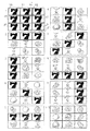
図3は、飾り図柄用可変表示装置の各飾り図柄表示部によって表示される可変停止時の表示結果が予め定められた特定の表示態様となった場合を示した表示画面図である。図3の一番左上に示された画面図では、各飾り図柄表示部2a〜2iにより「7」が表示結果として導出表示されている。この場合にはすべての飾り図柄表示部2a〜2iを枠で囲む表示が行なわれる。その下の表示画面図においては、横方向上段の当りライン上において「777」が揃った状態が示されている。そして、「777」がそろった飾り図柄表示部2a,2b,2gを枠で囲む表示が行なわれる。その下の表示画面図においては、縦方向左側の当りラインにおいて「777」が揃った状態とそれを枠で囲んだ状態が示されている。その下の表示画面図においては、左上から右下に向かう斜め方向に「777」が揃った状態とそれを枠で囲んだ状態が示されている。その下の表示画面図においては、横方向中段の当りラインにおいて「777」が揃った状態とそれを枠で囲んだ状態が示されている。
【0042】
図3の右上の表示画面図においては、縦方向中央の当りライン上において「777」が揃った状態とそれを枠で囲んだ状態が示されている。その下の表示画面図においては、左下から右上に向かう斜めの当りライン上において「777」が揃った状態とそれを枠で囲んだ状態が示されている。その下の表示画面図においては、横方向下段の当りライン上において「777」が揃った状態とそれを枠で囲んだ状態が示されている。その下の表示画面図においては、縦方向右側の当りライン上において「777」が揃った状態とそれを枠で囲んだ状態が示されている。その下の表示画面図においては、すべての飾り図柄表示部2a〜2iにおいてフルーツ図柄が揃った状態と、すべての飾り図柄表示部2a〜2iを枠で囲んだ状態とが示されている。
【0043】
この図3には大当り状態が発生する特定の表示態様が10種類示されているが、この10種類の表示態様のいずれが揃ったとしても、前述したように可変入賞球装置50の第1の状態への駆動制御の態様は同じである。また、この図3に示された特定の表示態様の他の例としては、たとえば、横方向上段と左上から右下へ向かう斜め方向との2本の当りライン上において共に「777」が揃ったり、あるいは斜め対角線上の2本と横方向1本または縦方向1本の合計3本の当りライン上において「777」が揃う場合がある。このような場合においても、付与される遊技価値としての可変入賞球装置50の第1の状態への駆動制御の態様は同じである。
【0044】
図3のたとえば右上端に示された表示画面図においては、飾り図柄表示部2aや2eに、星印マークの図柄が中央に示されており、その上下にフルーツ図柄の一部が示されている。これは、図2で説明したように、星印マークの図柄はいくら当りライン上に3つ揃ったとしても大当り状態にはならない外れ図柄であるために、飾り図柄用可変表示装置の表示結果が外れ図柄となった場合にこの星印マークの図柄を見た遊技者があまり不愉快に感じないようにするために極力ズーム縮小して表示した結果、この星印マークの外れ図柄の前後の図柄が1つの飾り図柄表示部2a,2eに一部入り込んでしまったのである。この前後の図柄の一部が1つの飾り図柄表示部に入り込んだ原因が、外れ図柄のズーム縮小表示であるために、この一部入り混んだ図柄の種類までは必ずしも遊技者が認識できる必要はない。たとえば、図2に示された左側の図柄表示列の上から4番目にはオレンジのフルーツ図柄がまるごと表示されており、一方、右側に示された図柄表示列の上から12番目にはスライスされたオレンジのフルーツ図柄が示されており、これらフルーツ図柄の下方の一部分がある飾り図柄表示部に入り込んだ形で示された場合には、まるごとオレンジのフルーツ図柄かスライスオレンジのフルーツ図柄かの区別はつかないのである。
【0045】
一方、図3の表示画面図は、飾り図柄用可変表示装置1の可変停止時の表示結果を示したものであるが、可変表示中においては、前述したように、図2に示された図柄列が各飾り図柄表示部において順次スクロール表示されるために、各飾り図柄表示部2a〜2iにおいては、1つまたは2つまたは3つの図柄(図柄の一部を含む)が可変表示される状態となる。
【0046】
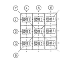
図4は、飾り図柄用可変表示装置1の当りラインと図柄との配置関係を説明するための説明図である。飾り図柄用可変表示装置1は、前述したように、3行×3列の合計9個の飾り図柄表示部2a〜2iを有しており、それぞれの飾り図柄表示部により、図示するように、図柄1〜図柄9の9個の飾り図柄が可変表示される。そして、横方向3行と縦方向3列と斜め対角線上に2本の合計8本の当りライン▲1▼〜▲8▼が定められており、この8本の当りライン▲1▼〜▲8▼のうちの少なくともいずれか1つの当りライン上において、「777」の図柄のぞろめが揃うか、あるいは、すべての飾り図柄表示部2a〜2iの表示結果がすべてフルーツ図柄である場合には、大当り状態が発生する。
【0047】
図5は、大当りが発生する飾り図柄用可変表示装置1の表示結果の表示態様の種類を示した表を表わす図である。この図の左上に示された「C RND LINE」は、後述の当り図柄決定用のカウンタであり、0から順次カウントアップして上限である85までカウントアップした後再度0から繰返しカウントアップするものである。そして、所定のタイミングでこのC RND LINEの値が読出され、そのときの値は「C RND LINE」の下の列に示された複数の値の中のいずれかに該当すれば、その該当する欄の右に示された当りライン上に「777」が停止表示されるように制御される。たとえば、C RND LINEのカウント値が「24」であった場合には、図4に示した▲1▼の当りライン上に「777」が揃うように制御される。
【0048】
また、C RND LINEのカウント値が「85」であった場合には、図4に示した▲8▼の当りライン上に「777」が揃うように制御される。さらに、C
RND LINEのカウント値が「7」であった場合には、すべての飾り図柄表示部2a〜2iにフルーツ図柄が表示されるように制御される。図5に示したように、飾り図柄用可変表示装置1の大当りが発生する表示結果は、9種類存在する。
【0049】
このように、図柄の組合せの総数が少ない特別図柄用可変表示装置60の表示内容に対応するように、図柄の組合せの総数が多い飾り図柄用可変表示装置1の表示がなされる。このため、遊技者に対して表示する図柄の組合せを、飾り図柄により、バラエティに富んだものにすることができる。
【0050】
図6は、パチンコ遊技機に用いられる制御回路を示すブロック図である。パチンコ遊技機の制御回路は、各種機器を制御するためのプログラムに従って遊技機制御を行なうための基本回路24と、始動入賞玉検出スイッチ4aと特定入賞玉検出スイッチ6と入賞玉検出スイッチ7とからの検出信号をメイン基本回路24に与えるためのスイッチ回路22と、メイン基本回路24の指令に従ってソレノイド8を駆動するソレノイド回路26と、メイン基本回路24から与えられるデータに従って、大当りが発生した旨を示す大当り情報や飾り図柄用可変表示装置1の可変表示に利用された始動入賞玉の個数を表わす有効始動情報をホストコンピュータであるホール用管理コンピュータ等に対して出力する情報出力回路28と、メイン基本回路24から与えられるデータに従って特別図柄可変表示装置60と始動記憶数表示器10とV表示LED17と入賞個数表示器9と各種装飾用のランプやLED16とを駆動するためのLED回路23とを含む。さらに、基本回路24には、制御用プログラム等を記憶しているROM31と、そのプログラムに従って制御動作を行なうためのCPU30と、RAM32と、I/Oポート33さらにはクロック発生回路(図示せず)とが設けられている。
【0051】
さらに、メイン基本回路24には、電源投入時にメイン基本回路24をリセットするための初期リセット回路19と、メイン基本回路24に対し定期的(たとえば2msec毎)にリセットパルスを与え、所定のゲーム制御用プログラムを先頭から繰返し実行するための定期リセット回路20と、メイン基本回路24から与えられるアドレス信号をデコードし、メイン基本回路24内に含まれるROM31,RAM32,I/Oポート33等のいずれか1つを選択するための信号を出力するためのアドレスデコード回路18と、メイン基本回路24から与えられる音データに従ってスピーカ210を駆動し、効果音等を発生させるための音発生,増幅回路21とが接続されている。さらに、パチンコ遊技機の制御回路には、AC24Vの交流電源に接続され、複数種類の直流の電圧を発生させる電源回路29が含まれている。
【0052】
さらに、制御回路には、基本回路24からの可変表示制御指令信号に従って飾り図柄可変表示装置1の画像表示装置2に対し可変表示制御信号を与える液晶表示回路25が設けられている。また、画像表示装置2は、サブCPU34、ROM35およびRAM36を備えている。ROM35には、飾り図柄用可変表示装置1により表示される飾り図柄の画像データ、キャラクタ画像の画像データおよびアニメーション画像の画像データ等のデータが記憶されている。
【0053】
RAM36は、画像表示を行なうための作業領域等として用いられる。サブCPU34は、液晶表示回路25から受けた可変表示指令信号に応答して、ROM35に記憶されている画像表示用のプログラムおよびデータに基づいて、RAM36を作業領域として使用しながら画像表示制御を行なう。具体的には、受取った可変表示制御信号に応答して、ROM35から画像表示用のデータを読出し、そのデータに対して、画像表示のための割付けおよび加工等の処理を行ない、画像表示を行なうためのデータを作成し、その作成したデータに基づいて、画像表示装置2に飾り図柄の画像、キャラクタ画像、およびアニメーション画像等を表示する制御を行なう。
【0054】
図7は、遊技制御,特別図柄用可変表示装置60の可変表示制御,飾り図柄用可変表示装置1の可変表示制御に用いられる各種ランダムカウンタを説明するための説明図である。ランダムカウンタは、以下に示す16種類が代表例として挙げられる。それぞれのランダムカウンタは、前述した基本回路24によりカウント動作される。
【0055】
ここで、前述の基本回路24に設けられたCPU30は、定期的(0.002秒毎)に定期リセット回路20からリセット信号が入力され、プログラムを先頭から実行してその最後まで実行したアドレスでリセット待ち状態となっており、前記リセット信号が入力されることにより再度プログラムを先頭から実行しなおすことを繰返し、リセット信号の入力毎にプログラムを先頭から最後まで実行することを繰返すことにより、パチンコ遊技機の遊技状態を制御できるように構成されている。
【0056】
C RNDは、大当り状態(特定遊技状態)を発生させるか否かを事前に決定するために用いられ、「0」からカウントアップしてその上限である「239」までカウントアップし、再度「0」からカウントアップしなおすように構成されている。
【0057】
C RND Lは、特別図柄用可変表示装置60の左特別図柄可変表示部の停止時に表示される左特別図柄を事前に決定するために用いられる。このC RND Lは「0」からカウントアップしてその上限である「14」までカウントアップした後、再度「0」からカウントアップし直されるものである。
【0058】
C RND Cは、特別図柄用可変表示装置60の中特別図柄可変表示部の停止時に表示される中特別図柄を事前に決定するために用いられる。このC RND Cは,「0」からカウントアップしてその上限である「14」までカウントアップし、その後再度「0」からカウントアップし直されるものである。
【0059】
C RND Rは、特別図柄用可変表示装置60の右特別図柄可変表示部の停止時に表示される右特別図柄を事前に決定するために用いられる。このC RND Rは,「0」からカウントアップしてその上限である「14」までカウントアップし、再度「0」からカウントアップし直すように構成されている。
【0060】
C RND R1は、飾り図柄用可変表示装置1においてリーチ表示をするか否かを決定するためのものであり、「0」からカウントアップしてその上限である「15」までカウントアップした後、再度「0」からカウントアップし直されるものである。
【0061】
C RND R2は、リーチ表示の種類を決定するために用いられるものである。このリーチ表示の種類は、複数種類予め用意されており、その中からC RND R2の値によりリーチ表示の種類が選択される。このC RND R2は、「0」からカウントアップしてその上限である「25」までカウントアップした後、再度「0」からカウントアップし直されるものである。
【0062】
C RND LINEは、飾り図柄用可変表示装置1の当り図柄を決定するために用いられるものである。このC RND LINEは、「0」からカウントアップしてのその上限である「85」までカウントアップした後、再度「0」からカウントアップし直されるものである。
【0063】
C RND ZU1〜ZU9は、飾り図柄用可変表示装置1の外れ図柄を決定するために用いられるものである。具体的には、C RND ZU1〜ZU9は、画像表示装置2に表示される飾り図柄表示部2a〜2iにそれぞれ対応し、対応する飾り図柄表示部の外れ図柄の決定に用いられる。C RND ZU1〜ZU6の6個の外れ図柄決定用のカウンタの各々は、「0」からカウントアップしてその上限である「8」までカウントアップした後、再度「0」からカウントアップし直されるものである。C RND ZU7〜ZU9の3つの外れ図柄決定用のカウンタの各々は、「0」からカウントアップしてその上限である「20」までカウントアップした後、再度「0」からカウントアップし直されるものである。
【0064】
以上に説明した各種のランダムカウンタには、ランダムカウンタ毎にカウントの加算更新タイミングが定められている。これにより、各ランダムカウンタは、独立的に加算更新される。
【0065】
次に、ランダムカウンタの値により大当りを発生させるか否かを事前に決定するための手順を説明する。図8は、ランダムカウンタの値により大当りを発生させるか否かを事前に決定するための手順を示すフローチャートである。
【0066】
パチンコ玉が始動入賞口4に入賞して始動入賞玉検出スイッチ4aにより検出されれば、その時点におけるC RNDの値を抽出し、その値が「4」のときに大当りを発生させることが事前決定される。その場合における特別図柄用可変表示装置60および飾り図柄用可変表示装置1のそれぞれの大当り図柄は、次のように決定される。特別図柄用可変表示装置60では、C RND Lの抽出値により、大当りとなる図柄が決定される。飾り図柄用可変表示装置1においては、C RND LINEの抽出値により、大当りとなる図柄が決定される。
【0067】
一方、C RNDの抽出値が「4」以外のときには、外れが事前決定される。その場合における特別図柄用可変表示装置60および飾り図柄用可変表示装置1のそれぞれの外れ図柄(外れ予定停止図柄)は、次のように決定される。特別図柄用可変表示装置60では、C RND Lの抽出値により左特別図柄の予定停止図柄が決定され、C RND Cの値により中特別図柄の予定停止図柄が決定され、C RND Rの値により右特別図柄の予定停止図柄が決定される。
なお、左,中,右の3つの特別図柄の予定停止図柄を決定した際に、その決定内容がたとえばぞろ目となり大当りを発生させるための図柄の組合せが偶然一致した場合には、C RND Cの抽出値に「1」を加算して強制的に外れの図柄となるように制御する。
【0068】
また、遊技状態が後述する高確率状態(特別遊技状態)のときには、C RNDの抽出値が、4,6,8,12,14のときに大当りを発生させることが事前決定され、それ以外のときに外れが事前決定される。
【0069】
ここで、高確率状態について説明する。高確率状態とは、大当りが発生する確率が向上した状態であり、この高確率状態においては、以下のような制御が行なわれる。大当り状態の発生時における特別図柄可変表示装置60および飾り図柄用可変表示装置1の各々の表示結果が予め定められた特別の識別情報の組合せとなっていた場合に、以降の大当りが発生する確率が向上する高確率状態に制御される。そして、この高確率状態中においては、特別図柄用可変表示装置60および飾り図柄用可変表示装置1の各々により表示される大当りとなるように予め定められた特定の識別情報の組合せ(特定の表示態様)の表示される確率が向上するのであり、それらの可変表示装置により特定の識別情報の組合せが表示された場合には、再度大当り制御が開始される。このような高確率状態は、確率向上状態または確率変動状態とも呼ばれる。
【0070】
さらに、このパチンコ遊技機においては、特別遊技状態である高確率状態に制御された場合において、特別図柄用可変表示装置60および飾り図柄用可変表示装置1のそれぞれの可変表示期間を短縮する変動時間短縮制御が行なわれる。この変動時間短縮制御が実行されると、特別図柄用可変表示装置60および飾り図柄用可変表示装置1のそれぞれの可変表示結果が早期に得られるため、可変表示に関与しない無駄な入賞を減らすことが可能になるとともに、早期に大当り(特定遊技状態)を発生させることが可能になる。
【0071】
飾り図柄用可変表示装置1では、C RND ZU1〜ZU9の抽出値により飾り図柄表示部2a〜2iのそれぞれの飾り図柄の予定停止図柄が決定される。なお、飾り図柄表示部2a〜2iの9つの予定停止図柄を決定した際に、その決定内容がたとえばぞろ目となり大当りを発生させるための図柄の組合せが偶然発生した場合には、たとえば、C RND ZU9(飾り図柄表示部2iに対応)の抽出値に「1」を加算して強制的に外れの図柄となるように制御する等、そのような図柄を決定する一部のランダムカウンタの抽出値に「1」を加算して強制的に外れの図柄とする。
【0072】
次に、リーチ表示を行なうか否かの決定方法について説明する。C RND
R1の抽出値が「0」である場合には、リーチ表示を行なうことが決定される。一方、C RND R1の抽出値が「1」〜「15」である場合には、リーチ表示を行なわない通常表示を行なうことが決定される。なお、C RNDの値に基づいて大当りが事前決定された場合には、C RND R1の値によらず、リーチ表示を行なうことが強制的に決定される。
【0073】
つぎに、C RND R2の抽出値と、決定されるリーチの種類との関係について説明する。C RND R2の抽出値に基づくリーチの種類の決定は、以下に示すリーチ種類決定テーブルを用いて行なわれる。
【0074】
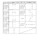
図9は、リーチ種類決定テーブルの内容を示す説明図である。この図9に示されるリーチ種類決定テーブルにおいては、遊技状態ごとにC RND R2の抽出値と、実行するリーチの種類との関係が予め定められている。詳しくは次のとおりである。遊技状態は、外れ時および大当り時の2種類に分類されている。
【0075】
外れ時の場合は、C RND R2の抽出値と、リーチの種類との関係が以下のように定められている。抽出値が「0」〜「19」である場合にはノーマルリーチの実行が決定される。抽出値が「20」〜「22」である場合には、スーパーリーチ1の実行が決定される。抽出値が「23」,「24」である場合には、スーパーリーチ2の実行が決定される。抽出値が「25」である場合には、スーパーリーチ3の実行が決定される。
【0076】
大当り時の場合は、C RND R2の抽出値と、リーチの種類との関係が以下のように定められている。抽出値が「0」〜「7」である場合には、ノーマルリーチの実行が決定される。抽出値が「8」〜「13」である場合には、スーパーリーチ1の実行が決定される。抽出値が「14」〜「19」である場合には、スーパーリーチ2の実行が決定される。抽出値が「20」〜「25」である場合には、スーパーリーチ3の実行が決定される。これらのノーマルリーチおよびスーパーリーチ1〜3は、飾り図柄用可変表示装置1に表示されるリーチの種類である。
【0077】
ここで、ノーマルリーチとは、比較的出現頻度が高くその代わりに大当りとなる割合が低い通常のリーチ状態をいう。また、スーパーリーチとは、リーチ表示後の停止図柄が大当りになる割合が高く設定されているリーチをいう。すなわち、飾り図柄用可変表示装置1においてスーパーリーチが表示されると、その後の停止図柄が大当り図柄の組合せになる割合がノーマルリーチの場合よりも高いのである。このパチンコ遊技機の場合には、スーパーリーチ1、スーパーリーチ2およびスーパーリーチ3の3種類のスーパーリーチが用意されている。これらのスーパーリーチは、たとえば、リーチ表示時の表示画像が異なるものである。また、各スーパーリーチの表示画像は、ノーマルリーチの表示画像と異なる。
【0078】
このように、この遊技機においては、たとえば、スーパーリーチ1〜スーパーリーチ3の3種類のスーパーリーチを表示することが可能である。したがって、遊技者は、飾り図柄用可変表示装置1にスーパーリーチが表示されると、大当りの発生に対する期待感が高くなる。このため、スーパーリーチを表示可能にすることにより、遊技者の興趣を向上させることができる。
【0079】
図10および図11は、飾り図柄用可変表示装置1における時間の変化に伴う各飾り図柄表示部2a〜2iの制御の状態を示すタイミングチャートである。
【0080】
パチンコ玉が始動入賞口4に入賞して始動入賞玉検出スイッチ4aにより検出されれば、図10の左上に示すように、その検出パルスがONとなって基本回路24に入力される。その検出パルスの立上がりのタイミングに従って、基本回路は、C RNDの値の抽出および格納を行なうとともに、C RND ZU1〜ZU9の値の抽出を行なう。これらのC RND ZU1〜ZU9のカウント値が、図2に示したソフト上のシンボルに相当し、カウント値がそのままソフト上のシンボルとなり、そのソフト上のシンボルに相当する図柄が該当する飾り図柄表示部2a〜2iで停止表示されるように制御される。
【0081】
次に、始動入賞玉検出スイッチ4aの検出パルスの立下がりのタイミング(立上がり時点より0.002秒後)で、既に格納されているC RNDの値の読出しが行なわれるとともに、この読出された値が予め定められた大当りに該当する値「4」であるか否かの判定が行なわれる。さらに、そのタイミングにおいては、C RND R1,R2の抽出も行なわれる。さらに、C RNDの抽出値に基づく大当りの判定において、大当りを発生させることが決定された場合には、C RND LINEの値の抽出動作が行なわれる。
【0082】
次に、始動入賞玉検出スイッチ4aの検出パルスの立上がりから0.004〜0.022秒の後に、C RND L,C,Rのそれぞれの値の抽出動作が行なわれ、それと同時に、特別図柄用可変表示装置60および飾り図柄用可変表示装置1のそれぞれにおいてすべての図柄が一斉に変動を開始する。
【0083】
特別図柄用可変表示装置60に関しては、左特別図柄可変表示部、右特別図柄可変表示部、中特別図柄可変表示部の順に可変表示を停止させる制御が行なわれる。その場合の停止図柄は、次のように決定される。C RNDの抽出値の判定により大当りを発生させることが決定された場合には、C RND C,Rの値が、C RND Lの抽出値に揃えられる。これにより、大当り時の予定停止図柄が決定される。一方、C RNDの抽出値の判定により外れにすることが決定された場合には、C RND L,C,Rのそれぞれの抽出値に基づいて、左,中,右特別図柄可変表示部のそれぞれの予定停止図柄が決定される。ここでは、特別図柄用可変表示装置60の制御タイミングの図示は省略し、主に、飾り図柄用可変表示装置1の制御タイミングの説明を行なう。
【0084】
図10には、リーチ状態が発生しない通常状態における飾り図柄用可変表示装置1の制御タイミングが示されており、図11には、リーチ状態が発生する場合の制御タイミングが示されている。
【0085】
図10に示されるリーチ状態が発生しない通常状態の場合には、飾り図柄表示部2a,2bが、可変表示開始後4.400秒(6600ドット変動するのに要する時間)変動した後、C RND ZU1,2あるいはC RND LINEの抽出値に従って事前決定された図柄(以下予定停止図柄という)の512ドット手前の図柄データがセットされてそのセットされた図柄データを表示する制御が行なわれる。
【0086】
そして、図10に示すように、0.700秒(512ドット変動するのに要する時間)だけ飾り図柄表示部2a,2bの変動を続行させた後、その飾り図柄表示部2a,2bを停止させる。その結果、前述した予定停止図柄まで変動した状態で飾り図柄表示部2a,2bが停止することとなり、飾り図柄表示部2a,2bにより予定停止図柄が停止表示されることとなる。
【0087】
このように、飾り図柄表示部2a,2bの可変表示が停止間近になった時点で予定停止図柄の少し手前の図柄を表示する図柄切換表示制御が行なわれる。
【0088】
飾り図柄表示部2c〜2fの場合にも、可変開始してから5.100秒(7650ドット分変動するのに要する時間)変動した後、前述した表示図柄切換制御が行なわれ、その後0.700秒可変表示が続行されて停止される。飾り図柄表示部2e,2hも同様に、5.800秒(8700ドット分変動するのに要する時間)可変表示された後、前述した表示図柄切換制御が行なわれる。飾り図柄表示部2iの場合も、6.500秒(9750ドット分変動するのに要する時間)可変表示された後、前述した表示図柄切換制御が行なわれる。
【0089】
このように、表示図柄切換制御を行なう理由は、各飾り図柄表示部が可変開始されてからそれぞれに定められた一定時間が経過した段階で停止されるのであるが、実際に停止する予定停止図柄は順次カウンタ(C RND ZU1〜ZU9)の抽出値次第でランダムに決定されるために、図柄切換表示制御を行なわない場合にはその決定された予定停止図柄のところまで可変表示させた後停止させざるを得ず、その予定停止図柄のところまで可変表示させるのに要する時間がランダムとなり、可変開始してから実際に停止するまでの可変表示時間がランダムとなってしまうのであり、そのような可変表示時間の不規則性を排除するために、途中で表示図柄切換制御を行なうのである。
【0090】
図11は、飾り図柄表示部2iの停止時の表示図柄次第では大当りが発生するというリーチ状態が生ずる場合の動作を示したタイミングチャートである。飾り図柄表示部2a〜2hについては、図10で説明した制御動作と同様である。そして、飾り図柄表示部2iについては、可変開始されてから6.500秒(9750ドット分変動するのに要する時間)可変表示した後、図柄切換表示制御が行なわれる。この表示図柄切換制御は、ソフト上のシンボル00の図柄すなわち図2に従えば「7」の図柄データがセットされてその図柄が表示される。
【0091】
その後、飾り図柄表示部2iの可変表示速度が徐々に遅くなって遊技者がはっきり視認できる程度の速度となり、そのゆっくりとした可変表示を比較的長い時間続行させた後、C RND ZU9の抽出値に応じた図柄あるいは当りの場合には「7」やフルーツ図柄が可変表示された瞬間停止制御する。この表示図柄切換制御が行なわれてから実際に可変表示が停止するまでの時間は、予定停止図柄の種類次第で異なるのであり、7.958〜11.334秒(2272〜3088ドット分変動する時間)となる。
【0092】
このように、表示図柄切換制御が行なわれてから実際に可変表示が停止するまでの時間は、予定停止図柄の種類次第で異なるため、飾り図柄用可変表示装置1においては、次のようなリーチ状態も生じる。すなわち、通常状態では同時に可変停止する2つの飾り図柄表示部2g,2hのうちの一方の飾り図柄表示部の停止図柄次第では大当りが発生するというリーチ状態が生じる。その他に、2つの飾り図柄表示部(2gまたは2hのうち少なくとも一方と、2iと)の停止時の表示図柄次第では大当りが発生するという2箇所でリーチ状態が発生するいわゆるダブルリーチも生じる。なお、ここではこれらの詳細な説明は省略する。
【0093】
ここで説明した飾り図柄表示部2iの停止制御は、ノーマルリーチの場合の制御内容である。これに対し、スーパーリーチ1〜スーパーリーチ3が表示される場合には、表示内容がノーマルリーチの場合とは異なる。以下に、スーパーリーチ1〜3が表示される場合の飾り図柄表示部2iの停止制御について説明する。
【0094】
スーパーリーチ1〜スーパーリーチ3を表示することは、C RND R2の抽出値を判定することにより決定される。これらのスーパーリーチの表示が行なわれる場合には、図11に示される飾り図柄表示部2iの停止制御時において、次のような制御が行なわれる。
【0095】
まず、飾り図柄表示部2iの可変表示速度を徐々に遅くして、遊技者がはっきり認識できる程度の速度にし、そのゆっくりとした可変表示を所定時間続行させ、その可変表示を一旦停止させた後またはその可変表示継続中において、後述するキャラクタ画像を飾り図柄表示部2a〜2iに重ねて登場させる。そして、そのキャラクタ画像に所定の動作を行なわせ、そのキャラクタ画像の動作に応じて、飾り図柄表示部2iをスクロール表示以外の変化態様で再び可変表示させる。そのスクロール表示以外の変化態様には、後述するような飾り図柄の縦軸回転表示および飾り図柄のめくり表示が含まれる。スーパーリーチの表示時に動作するキャラクタ画像の動作内容は、スーパーリーチの種類ごとに異なる。
【0096】
そのようなスーパーリーチの表示が行なわれる場合、その表示が行なわれる前の段階で、キャラクタ画像を用いたスーパーリーチ表示予告が行なわれる。飾り図柄表示部2iは、スクロール表示以外の変化態様での可変表示が所定時間行なわれた後、停止制御される。スーパーリーチ1〜スーパーリーチ3は、それらの表示後の停止図柄が大当りになる割合がノーマルリーチの場合よりも高く設定されているものであるため、これらのスーパーリーチの表示が行なわれると、遊技者は、ノーマルリーチに比較して、大当りの発生に対する期待感が高まる。したがって、このようにスーパーリーチを表示することにより、遊技者の興趣を向上させることができる。
【0097】
次に、スーパーリーチを含むリーチ表示を行なうために実行されるリーチ表示処理の内容を説明する。このリーチ表示処理は、図6に示した基本回路24のCPU30が実行する制御用プログラムのメインルーチンの実行に付随して実行される。
【0098】
図12は、リーチ表示処理の制御動作を示すフローチャートである。図12を参照して、ステップS(以下単にSという)1により、始動入賞に応じて抽出されたC RNDの値により決定された当り外れの結果(大当りまたは大当り以外)が参照され、S2により、その参照結果が大当りであるか否かの判断がなされる。
【0099】
S2で大当りであると判断された場合は、S3に進み、大当りフラグがセットされ、その後、後述するS5に進む。ここで、大当りフラグとは、大当りを発生させることが事前決定された場合にセットされるフラグであり、S3においてセットされ、その後大当り状態が終了すると別のルーチンでクリアされる。
【0100】
一方、S2により、大当りではないと判断された場合には、S4に進み、リーチ表示がなされるか否かの判断がなされる。この判断は、C RND R1の値に基づいて行なわれる。S4でリーチ表示がなされないと判断された場合にはこのルーチンが終了する。一方、S4でリーチ表示が行なわれると判断された場合は、S5に進む。なお、S2で、大当りであると判断された場合には、強制的にリーチ表示が実行されるため、このようなリーチ表示をするか否かの判断は行なわれない。
【0101】
S5では、リーチ種類決定用の乱数であるC RND R2が参照される。次に、S6に進み、S5で参照したC RND R2の値に基づき図9に示されたリーチ種類決定テーブルを用いて、飾り図柄用可変表示装置1の画像表示装置2に表示するリーチの種類を決定する処理がなされる。
【0102】
次に、S7に進み、決定されたリーチの種類がスーパーリーチ(スーパーリーチ1〜スーパーリーチ3)であるか否かの判断がなされる。S7でリーチの種類がスーパーリーチではないと判断された場合は、S8に進み、ノーマルリーチに対応する画像を画像表示装置2に表示する処理が行なわれる。
【0103】
一方、S7でリーチの種類がスーパーリーチであると判断された場合は、S9に進み、決定されたスーパーリーチの種類に対して、動作するキャラクタを表示する処理がなされる。これにより、画像表示装置2にキャラクタ画像が表示され、そのキャラクタ画像が、その後に発生するスーパーリーチの種類に応じた動作を行なう。ここで、スーパーリーチの種類(スーパーリーチ1〜3)のそれぞれに対応して、キャラクタ画像の動作が定められている。その動作は、スーパーリーチ毎に異なる。このような動作を表示するための画像データは、ROM35に記憶されており、その画像データに基づいて、動作するキャラクタ画像が表示される。このようなキャラクタ画像の動作により、その後にその動作に応じた種類のスーパーリーチが表示されることが予告される。
【0104】
次に、S10に進み、決定された種類のスーパーリーチの画像を表示する処理がなされる。その後、この処理が終了する。
【0105】
次に、図12に示されたリーチ表示処理が実行されることにより得られる効果を説明する。
【0106】
スーパーリーチの表示を行なうことが事前決定された場合に、キャラクタ画像が表示され、そのキャラクタ画像が、その後に表示されるスーパーリーチの種類に対応する動作をする。すなわち、このキャラクタ画像の動作によりスーパーリーチの発生の予告報知が行なわれる。そして、そのようなキャラクタ画像の動作を見た遊技者は、スーパーリーチが発生することを認識し、期待感が高まる。
【0107】
その後、キャラクタ画像の動作に応じて、飾り図柄の可変表示の変化態様がスクロール表示からスクロール表示以外の変化態様にされることにより、スーパーリーチ表示がなされる。
【0108】
このように、キャラクタ画像の動作によりスーパーリーチの発生に関する予告報知がなされるため、特別のリーチ状態の発生前から遊技者の期待感を高めることができる。したがって、スーパーリーチの面白さを十分に演出し、遊技者の期待感および興趣をより一層向上させることができる。
【0109】
さらに、スーパーリーチは、複数種類予め設定されており、それらのうちから選択的に実行されるため、遊技者の面白味(遊技性)を向上させることができる。さらに、複数種類のスーパーリーチのそれぞれに対応してキャラクタ画像の動作が異なるようにキャラクタ画像の種類が設定されているため、キャラクタ画像による予告報知の態様を変化に富んだものにすることができる。
【0110】
このようなスーパーリーチの表示が行なわれる場合には、それまでにスクロール表示の変化態様により可変表示されていた飾り図柄が、キャラクタ画像の動作に応じてスクロール表示以外の変化態様に切換えられる表示制御が行なわれる。その表示制御は、以下に説明する可変表示切換処理により実行される。
【0111】
図13は、可変表示切換処理の処理手順を示すフローチャートである。この処理は、図12に示されるリーチ表示処理に関連して実行される。まず、ステップS(以下単にSという)11により、リーチ表示を行なうタイミングであるか否かの判断がなされる。S11で、リーチ表示をするタイミングではないと判断された場合には、この処理が終了する。一方、S11で、リーチ表示をするタイミングであると判断された場合には、S12に進み、スーパーリーチを表示するタイミングであるか否かの判断がなされる。S12で、スーパーリーチを表示するタイミングではないと判断された場合には、この処理が終了する。一方、S12で、スーパーリーチを表示するタイミングであると判断された場合には、S13に進む。
【0112】
S13では、スーパーリーチ時に表示するキャラクタ画像を表示中であるか否かの判断がなされる。S13で、キャラクタ画像の表示中であると判断された場合には、後述するS15に進む。一方、S13で、キャラクタ画像の表示中ではないと判断された場合には、S14に進み、スーパーリーチ用のキャラクタ画像を飾り図柄用可変表示装置1の画像表示装置2に表示する処理がなされる。その後、S15に進む。
【0113】
S15では、画像表示装置2に表示されたキャラクタ画像が後述するような所定の動作を実行したか否かの判断がなされる。S15で、キャラクタ画像が所定の動作をしていないと判断された場合には、この処理が終了する。一方、S15で、キャラクタ画像が所定の動作を実行したと判断された場合には、S16に進み、可変表示の変化態様を切換える処理がなされる。具体的には、それまでにスクロール表示により可変表示されていた飾り図柄の可変表示態様を、スクロール表示以外の可変表示態様(変化態様)に切換える。その具体例については後述する図14〜図16において説明する。S16の後、この処理が終了する。
【0114】
このように、スーパーリーチの表示が行なわれる場合には、キャラクタ画像が表示され、それまでにスクロール表示により可変表示されていた飾り図柄が、キャラクタ画像の動作に応じて、スクロール表示以外の変化態様に切換えられるため、可変表示内容を変化に富んだものにすることができ、遊技の面白味(遊技性)を向上させることができる。その結果として、遊技者の興趣を向上させることができる。
【0115】
次に、スーパーリーチ時に画像表示装置2に表示される画像の具体例を説明する。スーパーリーチ時には、キャラクタ画像が飾り図柄用可変表示装置1の画像表示装置2に表示され、そのキャラクタ画像が動作する表示が行なわれる。そして、そのキャラクタ画像の動作の態様に応じて、スクロール表示されている飾り図柄表示部2a〜2iの飾り図柄の表示態様が、スクロール表示以外の表示態様に切換えられる。その具体例を以下に3種類説明する。ここで、スーパーリーチ時には、9つの飾り図柄表示部のうち、たとえば、最後に飾り図柄表示部2iが可変表示を停止する。
【0116】
図14は、キャラクタ画像の動作の態様に応じて飾り図柄の可変表示態様を切換える第1の表示例を示す図である。
【0117】
飾り図柄用可変表示装置1の画像表示装置2の表示画像がリーチ状態になると、たとえば人形状のキャラクタ81が画像表示装置2の画面上の左下位置に登場する。この状態において、飾り図柄表示部2iはスクロール表示を行なっている。
【0118】
そして、そのキャラクタ81が、画面上の右方向へ移動して一旦停止し、画面の上方向へジャンプする。そして、そのキャラクタ81が、飾り図柄表示部2iの右側に位置し、手の部分で飾り図柄表示部2iの飾り図柄を順次めくっていく動作をする。
【0119】
これにより飾り図柄表示部2iの飾り図柄がめくられていき、新たな図柄の飾り図柄が飾り図柄表示部2iに順次現われる。このようにして、飾り図柄の可変表示が行なわれる。キャラクタ81によりめくられた飾り図柄(破線で図示)は、画面上の左斜め上方へ順次飛ばされて消滅する。
【0120】
このように、キャラクタ81が前述の所定の動作を行なうことに応じて、飾りの可変表示態様が、スクロール表示からスクロール表示以外のめくり表示の可変表示態様に切換えられる。
【0121】
このような表示状態が、1つの種類のスーパーリーチである。この場合、キャラクタ81が登場してからジャンプをした後、スーパーリーチの表示であるめくり表示が行なわれる。したがって、このキャラクタ81が登場してからジャンプをするまでの間の動作がスーパーリーチの発生を予告報知するための動作である。このため、このような予告報知の動作により、遊技者は、めくり表示が行なわれるスーパーリーチ状態の発生を前もって認識することができる。したがって、そのようなキャラクタ81の予告報知動作を見ることにより、遊技者は、スーパーリーチの発生および大当りの発生に対する期待感が高まる。
【0122】
なお、ここでは、キャラクタ81が登場すると、スーパーリーチが必ず発生することを説明した。しかし、これに限らず、キャラクタ81が登場しても、そのキャラクタ81がジャンプを行なわないことによりスーパーリーチが発生しない表示を所定の確率で行なうようにしてもよい。そのようにすれば、画像表示装置2の表示内容をさらに変化に富んだものにすることができる。この場合には、キャラクタ81がジャンプする動作がスーパーリーチの予告報知動作となる。
【0123】
図15は、キャラクタ画像の動作の態様に応じて飾り図柄の可変表示態様を切換える第2の表示例を示す図である。
【0124】
飾り図柄用可変表示装置1の画像表示装置2の表示画像がリーチ状態になると、たとえば人形状のキャラクタ81が画像表示装置2の画面上の左中位置に登場する。この状態において、飾り図柄表示部2iはスクロール表示を行なっている。
【0125】
そして、そのキャラクタ81が、画面上の右方向へ飛ぶ移動を行なう。その飛んだ際に、キャラクタ81は、飾り図柄表示部2i上を通過する。そして、その通過に応答して飾り図柄表示部2iが縦軸回転(破線で図示)をする。ここで、縦軸回転とは、画面の上下方向を軸(縦軸)として飾り図柄が回転する表示をいう。そのような縦軸回転により飾り図柄表示部2iが回転するごとに、飾り図柄表示部2iに新たな図柄の飾り図柄が順次現われる。これにより、飾り図柄の可変表示が行なわれる。
【0126】
このように、キャラクタ81が前述の所定の動作を行なうことに応じて、飾りの可変表示態様が、スクロール表示からスクロール表示以外の縦軸回転表示の可変表示態様に切換えられる。
【0127】
このような表示状態が1つの種類のスーパーリーチである。この場合、キャラクタ81が登場してから右方向へ飛んだ後、スーパーリーチ表示である縦軸回転表示が行なわれる。したがって、このキャラクタ81が登場してから右方向へ飛んでいる間の動作がスーパーリーチの予告報知動作である。この場合、キャラクタ81が登場してから右方向へ飛ぶ予告報知動作により、遊技者は、縦軸回転表示が行なわれるスーパーリーチ状態の発生を前もって認識することができる。したがって、そのようなキャラクタ81の予告報知動作を見ることにより、遊技者は、スーパーリーチの発生および大当りの発生に対する期待感が高まる。
【0128】
なお、ここでは、キャラクタ81が登場すると、スーパーリーチが必ず発生することを説明した。しかし、これに限らず、キャラクタ81が登場しても右方向へ飛ばないことによりスーパーリーチが発生しない表示を所定の確率で行なうようにしてもよい。そのようにすれば、画像表示装置2の表示内容をさらに変化に富んだものにすることができる。この場合には、キャラクタ81が右方向へ飛ぶ動作がスーパーリーチの予告報知動作となる。
【0129】
図16は、キャラクタ画像の動作の態様に応じて飾り図柄の可変表示態様を切換える第3の表示例を示す図である。
【0130】
飾り図柄用可変表示装置1の画像表示装置2の表示画像がリーチ状態になると、たとえば人形状のキャラクタ81が画像表示装置2の画面上の左下位置に登場する。この状態において、飾り図柄表示部2iはスクロール表示を行なっている。
【0131】
そして、そのキャラクタ81が、画面上の右方向へ移動して一旦停止し、画面の上方向へジャンプする。そして、そのキャラクタ81が、飾り図柄表示部2iの右側に位置し、キャラクタ81の尻の部分で飾り図柄表示部2iの飾り図柄を順次押すことにより、飾り図柄表示部2iの飾り図柄を順次めくっていく動作をする。これにより飾り図柄表示部2iの飾り図柄がめくられていき、新たな図柄の飾り図柄が飾り図柄表示部2iに順次現われる。このようにして、飾り図柄の可変表示が行なわれる。キャラクタ81によりめくられた飾り図柄(破線で図示)は、順次画面上の左方向へ飛ばされて消滅する。
【0132】
このように、キャラクタ81が前述の所定の動作を行なうことに応じて、飾り図柄の可変表示態様が、スクロール表示からスクロール表示以外のめくり表示の可変表示態様に切換えられる。
【0133】
このような表示状態が1つの種類のスーパーリーチである。この場合、キャラクタ81が登場してからジャンプをした後、スーパーリーチ表示であるめくり表示が行なわれる。したがって、このキャラクタ81が登場してからジャンプをするまでの動作が、図14の場合と同様に、スーパーリーチの発生の予告報知動作である。この予告報知動作により、遊技者は、めくり表示が行なわれるスーパーリーチ状態の発生を前もって認識することができる。したがって、そのようなキャラクタ81の予告報知動作を見ることにより、遊技者は、スーパーリーチの発生および大当りの発生に対する期待感が高まる。
【0134】
なお、ここでは、キャラクタ81が登場すると、スーパーリーチが必ず発生することを説明した。しかし、これに限らず、図14の場合と同様に、キャラクタ81が登場してもそのキャラクタ81がジャンプを行なわないことによりスーパーリーチが発生しない表示を所定の確率で行なうようにしてもよい。このようにすれば、画像表示装置2の表示内容をさらに変化に富んだものにすることができる。この場合には、キャラクタ81がジャンプする動作が、図14の場合と同様に、スーパーリーチの予告報知動作となる。
【0135】
スーパーリーチ1〜スーパーリーチ3の各々には、可変表示態様がキャラクタ画像の動作に応じて切換えられる前述したような表示内容のうちの1種類が固有の表示内容として予め定められており、スーパーリーチ1〜スーパーリーチ3を表示させることが決定された場合には、決定されたスーパーリーチに対応する表示が行なわれる。たとえば、スーパーリーチ1の表示を行なうことが決定された場合に図14の表示がなされ、スーパーリーチ2の表示を行なうことが決定された場合に図15の表示がなされ、スーパーリーチ3の表示を行なうことが決定された場合に図16の表示がなされるようにすればよい。
【0136】
このように、このパチンコ遊技機では、飾り図柄用可変表示装置1の飾り図柄の可変表示中において、飾り図柄の可変表示の変化態様が、キャラクタ画像の動作に応じてスクロール表示からスクロール表示以外の可変表示態様に切換えられる。このため、飾り図柄用可変表示装置1の可変表示の変化態様を変化に富んだものにすることができ、遊技としての面白味を向上させることができる。その結果として、このような可変表示を見る遊技者の興趣を向上させることができる。
【0137】
さらに、キャラクタ画像の動作に関連して飾り図柄の可変表示の変化態様が切換わるので、単に可変表示の変化態様を切換えるものに比べて面白味が向上するとともに、切換が行なわれたことを遊技者にわかりやすく(視認させやすく)することができる。
【0138】
また、スクロール表示からの切換え後の可変表示態様としては、めくり表示および縦軸回転表示等が代表例として挙げられる。このようなめくり表示および縦軸回転表示は、特殊な可変表示態様であり、表示態様がスクロール表示と大幅に異なるものであるため、スクロール表示からめくり表示または縦軸回転表示への切換えを行なうことにより、可変表示の表示態様の切換え前後の可変表示態様の変化を強調することができる。
【0139】
また、前述したように、キャラクタ画像の動作は、図14〜図16に示されたように複数種類用意され、それらの中からランダムカウンタC RND R2の値により選択された動作(リーチ動作)が実行されるようになっている。一方、それらのキャラクタ画像の各動作に対応して、スクロール表示からの切換え後の飾り図柄の可変表示態様が予め定められている。このため、同じキャラクタ画像が表示される場合でも、キャラクタ画像の選択された動作の種類に応じて切換え後の飾り図柄の可変表示の変化態様が異なるように表示制御がされる。したがって、可変表示の表示態様をさらに変化に富んだものにすることができる。
【0140】
なお、本実施の形態においては、スーパーリーチの表示が行なわれる場合にのみ、キャラクタ画像の表示を行なう制御およびそのキャラクタ画像の動作に応じた可変表示態様の切換えを行なう制御をするようにした。しかし、これに限らず、そのようなキャラクタ画像の表示制御およびそのキャラクタ画像の動作に応じた可変表示態様の切換え制御は、スーパーリーチ時以外の場合に行なってもよい。
【0141】
また、本実施の形態のパチンコ遊技機は、少なくともリーチが確定した後にキャラクタが出現するように構成したが、これに限らず、リーチが可変表示上まだ確定していない段階でキャラクタが出現,動作するように構成してもよい。さらに、キャラクタの動作により必ずしも可変表示方法がすべて変化せずに、ある割合で変化するようにしてもよい。これにより、遊技者にキャラクタの動作により可変表示態様が変化するかしないかの緊張感を付与でき、興趣が向上できる。
【0142】
また、前述した可変表示切換処理においては、可変表示の変化態様を、スクロール表示からめくり表示または縦軸回転表示に切換える例を説明したが、それは代表例の1つである。そのような可変表示の切換の具体例としては、前述した例を含めて以下に示すような例がある。
【0143】
可変表示態様の切換前の表示変化態様には、▲1▼スクロール表示,▲2▼切換表示,▲3▼回転表示,▲4▼変形表示,▲5▼めくり表示が含まれる。
【0144】
ここで、▲1▼のスクロール表示とは、前述した飾り図柄のスクロール表示に代表される可変表示である。▲2▼の切換表示とは、識別情報をその場で切換える可変表示である。また、▲3▼の回転表示とは、前述した縦軸回転表示を代表例とし、識別情報の回転に伴う可変表示である。また、▲4▼の変形表示とは、モーフィング表示等の形状変化表示を代表例とし、識別情報をある形状から他の形状に変形させていき、その変形に伴って可変表示を行なう表示である。▲5▼のめくり表示とは、前述した飾り図柄のめくり表示を代表例とする可変表示である。
【0145】
また、可変表示態様の切換後の表示変化態様(基本的には表示方法自体が変わるもの)には、前述した切換前の場合と同様に、▲1▼スクロール表示,▲2▼切換表示,▲3▼回転表示,▲4▼変形表示,▲5▼めくり表示が含まれる。すなわち、前述のように列挙された切換前の▲1▼〜▲5▼と、切換後の▲1▼〜▲5▼とが適宜組合せて用いられる。ただし、その場合において、切換前と、切換後との表示種類が一致する場合(たとえば、切換前がスクロール表示であり、かつ、切換後がスクロール表示である場合等)には、それらの表示について、たとえば次のように表示方法を異ならせることにより、変化態様を異ならせるようにする。
【0146】
▲1▼両方の表示変化態様がスクロール表示の場合には、変化態様の切換の前と後とでスクロール方向を変える。▲2▼両方の表示変化態様が切換表示の場合には、変化態様の切換の前と後とで切換表示の切換方法を変える。▲3▼両方の表示変化態様が回転表示の場合には、変化態様の切換の前と後とで回転方向を変える。▲4▼両方の表示変化態様が変形表示の場合には、変化態様の切換の前と後とで変形方法を変える。▲5▼両方の表示変化態様がめくり表示の場合には、変化態様の切換の前と後とでめくり方向を変える。
【0147】
また、前述した実施の形態においては、飾り図柄用可変表示装置1に含まれる画像表示装置2を飾り図柄の表示のために用いた。しかし、これに限らず、画像表示装置2は、特別図柄を表示するために用いてもよい。その場合には、7セグメントLEDよりなる特別図柄用可変表示装置60を用いずに、画像表示装置2を含む飾り図柄用可変表示装置1を特別図柄用の可変表示装置として用いる。
【0148】
また、キャラクタ画像(キャラクタ81)が出現した場合において、識別情報(飾り図柄)の可変表示の表示変化態様を切換える制御は、必ずしも行なわないようにしてもよい。すなわち、キャラクタ画像が出現した場合に識別情報の可変表示の表示変化態様を切換える制御に加えて、キャラクタ画像が出現しても、識別情報の表示変化態様が切換わらないようにする制御を所定条件下で行なうようにしてもよい。
【0149】
その具体例は、次のとおりである。リーチ状態が発生した場合に、表示においてキャラクタ画像が出現する。そして、識別情報の表示変化態様が切換えられるスーパーリーチを発生させる場合にはキャラクタ画像を動作させ、一方、スーパーリーチを発生させず、たとえば外れにする場合には、キャラクタ画像の動作を停止させるか、または、キャラクタ画像に予め定められた他の動作(スーパーリーチ発生前の動作以外の動作)をさせる。このようにすれば、スーパーリーチの出現率と、スーパーリーチの出現時の大当り発展率(スーパーリーチから大当りへ発展する確率)とをともに低下させることなく、キャラクタ画像の出現頻度を増加させることができる。その結果として、ゲーム性が向上する。
【0150】
次に、パチンコ遊技機が高確率状態に制御された場合において、特別図柄用可変表示装置60および飾り図柄用可変表示装置1のそれぞれの可変表示を停止させる制御である高確率時可変停止制御について説明する。この高確率時可変停止制御は、図6に示した基本回路24のCPU30が実行する制御用プログラムのメインルーチンの実行に付随して実行される。
【0151】
図17は、高確率時可変停止制御の制御動作を示すフローチャートである。図17を参照して、ステップS(以下単にSという)21により、現在が高確率状態であるか否かの判断がなされる。S21で、高確率状態ではないと判断された場合は、この制御の処理が終了する。一方、S21で、高確率状態であると判断された場合は、S22に進み、現在が、リーチ状態であるか否かの判断がなされる。
【0152】
S22により、リーチ状態でないと判断とされた場合、すなわち、高確率状態においてリーチ状態が発生していない場合には、S23に進み、第1の停止処理が実行される。この第1の停止処理においては、特別図柄用可変表示装置60および飾り図柄用可変表示装置1の可変表示期間を短縮する処理が行なわれる。すなわち、この第1の停止処理が実行されることにより、変動時間短縮制御が行なわれる。このS23の後、この制御の処理が終了する。
一方、S22で、リーチ状態であると判断された場合、すなわち、高確率状態においてリーチ状態が発生した場合には、S24に進み、第2の停止処理を実行する処理がなされる。この第2の停止処理においては、特別図柄用可変表示装置60および飾り図柄用可変表示装置1のそれぞれの可変表示期間を短縮するとともに、これらの可変表示装置において、リーチ状態が発生した後の表示結果の導出表示に至るまでの可変表示期間を、リーチ状態が発生しなかった場合のその後の表示結果の導出表示に至るまでの可変表示期間よりも長くする制御が行なわれる。すなわち、この第2の停止処理により、リーチ状態の発生が表示において確定した後の可変表示期間が、リーチ状態が発生しないことが表示において確定したその後の第1の停止処理による可変表示期間よりも長くされる。
【0153】
次に、図17に示した高確率時可変停止制御により行なわれる高確率状態での飾り図柄用可変表示装置1における各飾り図柄表示部2a〜2iの制御の状態について説明する。図18は、高確率時可変停止制御による高確率状態での飾り図柄用可変表示装置1における時間の変化に伴う各飾り図柄表示部2a〜2iの制御の状態を示すタイミングチャートである。
【0154】
パチンコ玉が始動入賞口4に入賞して始動入賞玉検出スイッチ4aによりその検出パルスがONとなってから飾り図柄表示部2a〜2iが変動を開始するまでの動作は、図10および図11に示した動作と同じであり、その後の動作が異なる。以下に、高確率状態時における飾り図柄表示部2a〜2iの表示制御をリーチ状態が発生しなかった場合と、リーチ状態が発生した場合とに分けて説明する。
【0155】
リーチ状態が発生しなかった場合の飾り図柄表示部2a〜2iの可変表示動作は、図10に示された可変表示動作と比べて、飾り図柄2a〜2iが変動を開始してから表示図柄切換制御が行なわれるまでの期間が、それぞれ0.5秒短縮される。一方、リーチ状態が発生した場合の飾り図柄表示部2a〜2iの動作は、基本的に、飾り図柄表示部2iの動作を除いて、リーチ状態が発生しなかった場合と同じである。すなわち、リーチ状態が発生した場合の飾り図柄表示部2iの動作は、変動を開始してから6.000秒まではリーチ状態が発生しなかった場合の動作と同じであり、その後は、リーチ状態が発生しなかった場合の表示図柄切換制御の時間(0.700秒)よりも長い3.000秒の時間において表示図柄切換制御が行なわれる。
【0156】
また、前述したように、飾り図柄用可変表示装置1は、特別図柄用可変表示装置60と連動した可変表示を行なうものであるため、高確率状態時には、特別図柄用可変表示装置60においても、図18に示されたタイミングと同期して、可変表示の開始、リーチ表示および可変表示の停止等の制御が実行される。
【0157】
このように、高確率状態においては、変動時間短縮制御が行なわれるため、始動入賞記憶の消化が通常時(高確率状態時以外時)よりも早くなる。これにより、高確率状態時において、可変表示に関与しない無駄な始動入賞を減少させることができる。さらに、高確率状態時においては、早期に大当りを発生させることができる。すなわち、高確率状態においては、大当りが発生する確率が通常時よりも高く設定されており、さらに、変動時間短縮制御が行なわれることにより早いタイミングで表示結果が得られるため、通常時よりも早期に大当りを発生させることができるのである。
【0158】
さらに、高確率状態においては、高確率時可変停止制御により、リーチ状態が発生した場合のその後の可変表示期間を、リーチ状態が発生しなかった場合のその後の可変表示期間よりも長くする制御が行なわれる。このため、高確率状態時におけるリーチ状態が発生した場合には、その後の可変表示が、遊技者の期待感を高めるに足り得る時間行なわれる。したがって、このパチンコ遊技機においては、変動時間短縮制御が実行される高確率状態時のリーチ状態において、遊技者の期待感を高めることができる。その結果として、このパチンコ遊技機では、可変表示の面白味を損なわないようにすることができる。
【0159】
このような種々の効果が得られることにより、このパチンコ遊技機においては、高確率状態において、大当りを早期に発生させることができ、かつ、可変表示の面白味を損なわないようにすることができる。
【0160】
次に、高確率状態時において、リーチ状態が発生した場合のその後の停止表示に至るまでのその他の表示の種類の例を説明する。
【0161】
前述した図17の高確率時可変停止制御においては、リーチ状態が発生した場合に実行される第2の処理(S24)として、リーチ状態の表示がなされてから可変表示が停止するまでの時間を長くする制御を行なった。このような時間の制御は、単なる一例である。第2の処理(S24)としては、表示時間の制御に加えて、または、表示時間の制御に代えて、以下に説明するような再可変表示、滑り表示、または、戻り表示等のその他の表示制御を行なってもよい。
【0162】
図19は、高確率状態時のリーチ状態において表示される再可変表示の表示の変化態様を示す説明図である。この図19においては、図中の上段から下段の方向へ向かう白抜矢符により時間経過が示されている。
【0163】
まず、図19の上から1段目の画像表示装置2の図の部分を参照して、画像表示装置2において、飾り図柄表示部2a〜2gが先に停止しており、飾り図柄表示部2aがスクロール表示を継続している。この時点では、飾り図柄表示部2dと、飾り図柄表示部2eとがともに「7」になっており、リーチ状態が発生している。次に、上から第2段目の画像表示装置2の図の部分を参照して、時間経過により飾り図柄表示部2iがフルーツ図柄で停止し、外れの停止図柄となっている。次に、上から3段目の画像表示装置2の図の部分を参照して、外れの停止図柄から飾り図柄表示部2iが可変表示を再び開始する。そして、その後、この飾り図柄表示部2iが停止し、最終的な表示結果が得られる。
【0164】
このように、再可変表示においては、1つの始動入賞記録に基づいて、一旦可変表示が停止し、かつ、その停止後さらに可変表示が行なわれる。なお、ここでは、1つの飾り図柄表示部2iのみが再可変表示をする例を説明したが、これに限らず、再可変表示は、複数の飾り図柄表示部で行なわれるように制御してもよい。
【0165】
図20は、高確率状態時のリーチ状態において表示される滑り表示の表示の変化態様を示す説明図である。この図20においては、図中の上段から下段の方向に向かう白抜矢符により時間経過が示されている。
【0166】
ここで、滑り表示とは、図柄の停止直前において、図柄を目視による停止予測位置から滑らせて停止させる表示である。まず、図20の上から1段目の画像表示装置2の図の部分を参照して、図19の場合と同様のリーチ状態が発生している。次に、上から2段目の画像表示装置2の図の部分を参照して、時間経過に伴って飾り図柄表示部2iの可変表示の速度が減速されていく。
【0167】
次に、上から3段目の画像表示装置2の図の部分を参照して、時間経過に伴って飾り図柄表示部2iの可変表示速度が極めて遅くなって、目視によりフルーツ図柄が停止すると予測させる表示が行なわれる。しかし、それ以後も飾り図柄表示部2iのゆっくりとした可変表示が継続されることにより、目視による停止予測位置から停止しようとした飾り図柄が滑るような表示がなされる。そして、そのように滑った結果として、上から4段目の画像表示装置2の図に示されるように、目視により停止すると予測されたフルーツ図柄以外の「7」が停止図柄となる。この例では、このように「7」が停止することにより、大当り状態が発生している。なお、滑り表示においては、このように大当りを発生させなくてもよい。
【0168】
図21は、高確率状態時のリーチ状態において表示される戻り表示の表示の変化態様を示す説明図である。この図21においては、図中の上段から下段の方向へ向かう白抜矢符により時間経過が示されている。
【0169】
まず、図21の上から1段目の画像表示装置2の図の部分を参照して、画像表示装置2において、前述した図19および図20の場合と同様のリーチ状態が発生している。次に、上から2段目の画像表示装置2の図の部分を参照して、時間経過に伴って飾り図柄表示部2iの可変表示速度が徐々に減速し、目視によって、大当りとなり得る「7」の飾り図柄が停止位置を通過する状態を確認させる表示が行なわれる。
【0170】
次に、上から3段目の画像表示装置2の図を参照して、時間経過に伴って、その後、飾り図柄表示部2iが、通常のスクロール方向とは逆方向にスクロール表示を行なう。これにより、先にゆっくりとしたスクロール表示により停止位置を一旦通過したと視認され得る表示が行なわれた飾り図柄が再び飾り図柄表示部2iに現れる。そして、その後、上から4段目の画像表示装置2の図の部分に示されるように、逆方向にスクロール表示していた飾り図柄表示部2iが最終的に停止する。ここでは、最終的な表示結果として予定停止位置を一旦通過した「7」が停止図柄となった例が示されている。この場合には、大当りが発生している。なお、戻り表示においては、このように大当りを発生させなくてもよい。
【0171】
このように、高確率状態でのリーチ状態において、このような再可変表示、滑り表示、または戻り表示が、可変表示時間を長くする制御に加えて、または、可変表示時間を長くする制御に代えて行なわれることにより、このパチンコ遊技機においては、変動時間短縮制御によって可変表示期間が短縮されながらも、これらの面白味がある可変表示によって、遊技者の期待感を高めることができ、可変表示の面白味を損なわないようにすることができる。
【0172】
なお、この実施の形態においては、高確率状態時のリーチ状態における表示の種類について、可変表示時間を長くする制御、再可変表示制御、滑り表示制御、および戻り表示制御について説明したが、これらは一例であり、これに限らず、遊技者の期待感を高めることが可能な特徴的な表示であれば、それ以外の表示を行なってもよい。
【0173】
また、このような高確率状態においても、前述したようなスーパーリーチ(スーパーリーチ1〜3)の表示が行なわれる。その場合のスーパーリーチの表示期間は、ノーマルリーチの場合の表示期間と比べて短縮してもよく、または、短縮しないでもよい。
【0174】
このように、高確率状態時においてスーパーリーチの表示が行なわれると、スーパーリーチと、ノーマルリーチとで可変表示の変化態様が異なるため、リーチ状態における可変表示の変化態様をバラエティに富んだものにすることができる。さらに、スーパーリーチが表示された場合には、大当りが発生しやすいため、遊技者の期待感をさらに高めることができる。
【0175】
その他の実施の形態
次に、この発明のその他の実施の形態について説明する。以上に示した実施の形態では、高確率状態において、リーチ状態が表示された場合と、高確率状態以外の通常状態においてリーチ状態が表示された場合とを比較した場合、たとえばスーパーリーチは、高確率状態であるか否かを問わず同様の確率で発生する。このため、遊技者は、高確率状態および通常状態のそれぞれでリーチ状態が生じた場合において、高確率状態の場合のほうが、通常状態の場合よりも大当りの発生確率が少し高く設定されていることを感じる程度である。すなわち、遊技者は、高確率状態において、リーチ表示の内容自体に対する特別な期待感を感じない。
【0176】
以下に説明するその他の実施の形態においては、高確率状態時のリーチ表示に対して特別な期待感を遊技者に感じさせるような制御について説明する。具体的には、そのような制御として、高確率時リーチ表示制御を行なう。
【0177】
図22は、その他の実施の形態による高確率時リーチ表示制御の制御動作を示すフローチャートである。
【0178】
この高確率時リーチ表示制御は、基本回路24のCPU30が実行する制御用プログラムのメインルーチンの実行に伴って実行される。
【0179】
図22を参照して、ステップS(単にSという)31により、現在が高確率状態であるか否かの判断がさなれる。S31で、高確率状態ではないと判断された場合には、この制御の処理を終了する。一方、S31で、高確率状態であると判断された場合には、S32に進む。
【0180】
S32では、リーチ時大当り表示確率向上処理が実行され、その後、この制御の処理が終了する。ここで、リーチ時大当り表示確率向上処理とは、高確率状態でリーチ状態が発生した場合において、そのリーチ状態の後に導出表示される表示結果が大当りの表示結果(特定の表示態様)になる確率を向上させる処理である。
【0181】
以下に、S32で実行されるリーチ時大当り表示確率向上処理の具体例を説明する。その具体例の1つとして次のような処理を行なう。すなわち、図7に示されるリーチ決定用のランダムカウンタC RND R1がとり得る範囲を大きくする。すなわち、図7においては、C RND R1の範囲が「0」〜「15」に設定されているが、リーチ時大当り表示確率向上処理においては、C RNDR1がとり得る範囲を、たとえば、「0」〜「31」に拡大する。この場合においてリーチ表示を行なうことを決定する値は、図7の場合と同様とする。このようにすれば、通常時においてC RND R1を用いて外れとなるリーチ表示を設定する確率が1/16であるのに対し、高確率時においてC RND R1を用いて外れとなるリーチ表示を決定する確率が1/32となる。
【0182】
したがって、このような処理を行なえば、高確率状態においては、通常状態と比べて、外れの表示結果になるリーチ表示がなされる頻度が低くなる。すなわち、高確率状態時においては、通常状態と比べて、リーチ表示がなされた場合に大当りの表示結果が導出表示される確率が高くなる。
【0183】
なお、ここでは、C RND R1がとり得る値の範囲を拡大する例を示したが、それに限らず、C RND R1の範囲は、高確率状態と、通常状態とで変化しないように一定にしておき、たとえば、通常状態において外れとなるリーチ表示を決定する値を2つの値にするとともに高確率状態において外れとなるリーチ表示を決定する値を1つの値にするなど、高確率状態においてリーチ表示を決定する値の個数を通常状態よりも少なくするようにしてもよい。
【0184】
また、リーチ時大当り表示確率向上処理の具体例としては、前述した処理に代えて、次のような処理を行なってもよい。すなわち、図7に示したC RND
R1を用いた外れとなるリーチ表示の決定は、通常状態においてのみ行ない、高確率状態時においては、C RND R1を用いた外れとなるリーチ表示の決定を行なわないようにする。そのようにすれば、高確率状態時において、リーチ表示後に外れの表示結果が導出表示されることが極めて少なくなる。すなわち、高確率状態においては、通常状態と比べて、リーチ表示がなされた場合の後に大当りの表示結果が導出表示される確率が高くなる。
【0185】
なお、以上の説明においては、高確率状態においてリーチ状態が表示されると、大当りの表示結果が導出される確率が高くなることを説明したが、その確率が100%になるようにしてもよい。
【0186】
このような高確率時リーチ表示制御が実行されると、高確率状態において、通常状態と比べて、リーチ表示がなされた後に大当りの表示結果が導出表示される確率が高くなるため、遊技者は、高確率状態におけるリーチ表示自体に対して特別な期待感を感じると考えられる。その結果として、高確率状態におけるリーチ状態の表示により、遊技者の期待感をさらに高めることができる。
【0187】
以下、本発明の主な変形例等の特徴点を列挙する。
(1) 図6に示された基本回路24のCPU30および画像表示装置2のサブCPU34により、または、画像表示装置2のサブCPU34のみにより構成される可変表示制御手段は、特別遊技状態(高確率状態)において、リーチ状態が発生した場合のその後の表示結果の導出表示に至るまでの可変表示の種類を、特別のリーチ状態が発生した場合と、特別のリーチ状態が発生しなかった場合とで異ならせる制御を行なうが、その場合の特別のリーチ状態(スーパーリーチ1〜3)には、図14〜図16に示されるようなリーチ表示の途中で可変表示の変化態様を切換える表示が含まれる。さらに具体的には、特別のリーチ状態には、図14〜図16に示されるように、キャラクタ画像を用いた縦軸回転表示またはめくり表示が含まれる。
【0188】
(2) 前記可変表示制御手段は、特別遊技状態(高確率状態)でリーチ状態を発生させる場合において、導出表示される表示結果が特定の表示態様(大当りの表示態様)となる確率を向上させる表示制御を行なうが、その確率は、最大限100%に向上させてもよい。
【0189】
(3) この実施の形態においては、表示結果が変化可能な可変表示装置として、特別図柄用可変表示装置60および飾り図柄用可変表示装置1の2つの可変表示装置を有する場合を説明したが、これに限らず、可変表示装置は、特別図柄用可変表示装置60および飾り図柄用可変表示装置1の一方の可変表示装置のみであってもよい。
【0190】
(4) この実施の形態においては、飾り図柄用可変表示装置1は、液晶表示装置のものを示した。しかし、これに限らず、飾り図柄用可変表示装置は、CRT表示装置、プラズマ表示装置、または、マトリクスLED表示装置等のその他の画像表示装置を用いてもよい。
【0191】
(5) この実施の形態では、可変表示装置として、特別図柄用可変表示装置60および飾り図柄用可変表示装置1の構成に示されたような電気式の表示装置を示した。しかし、これに限らず、可変表示装置は、次のような機械式の表示装置を用いてもよい。すなわち、可変表示装置は、回転ドラム式、複数の図柄が付されたベルトが巡回することにより表示状態が変化するいわゆるベルト式、リーフ式、複数の図柄が付された回転円盤が回転することにより表示状態が変化するいわゆるディスク式等の機械式のものであってもよい。
【0192】
【課題を解決するための手段の具体例】
図1に示した特別図柄用可変表示装置60および飾り図柄用可変表示装置1の両方または一方により、表示状態が変化可能な可変表示装置が構成されている。図6に示された基本回路24のCPU30により、所定条件の成立により遊技機を特定遊技状態が発生しやすい特別遊技状態に制御する遊技制御手段が構成されている。前記特定遊技状態には、大当り状態が含まれる。前記特別遊技状態には、高確率状態が含まれる。図6に示された基本回路24のCPU30および画像表示装置2のサブCPU34により、または、画像表示装置2のサブCPU34のみにより、可変表示装置を可変開始させた後表示結果を導出表示させる制御を行なう可変表示制御手段が構成されている。この可変表示制御手段は、遊技機が特別遊技状態に制御されている場合において、リーチ状態が発生した場合のその後の表示結果の導出表示に至るまでの可変表示の種類と、リーチ状態が発生しなかった場合のその後の表示結果の導出表示に至るまでの可変表示の種類とを異ならせる制御を行なう。
【0193】
(2) 前記可変表示制御手段は、特別遊技状態(高確率状態)においてリーチ状態が発生した場合と、リーチ状態が発生しない場合とでその後の表示結果の導出表示に至るまでの可変表示の種類を異ならせる制御として、リーチ状態が発生した場合の表示結果の導出表示に至るまでの期間を、リーチ状態が発生しなかった場合の表示結果の導出表示に至るまでの期間よりも長くする制御(図11に示された高確率時可変停止制御)を行なう。
【0194】
(3) 前記可変表示制御手段は、特別遊技状態(高確率状態)において、リーチ状態が発生した場合と、リーチ状態が発生しない場合とでその後の表示結果の導出表示に至るまでの可変表示の種類を異ならせる制御として、リーチ状態が発生した場合の可変表示の変化態様を、リーチ状態が発生しない場合の可変表示状態の変化態様とは異なる変化態様にする制御(図17に示された高確率時可変停止制御)を行なう。その場合の制御には、▲1▼図19に示された再可変表示制御,▲2▼図20に示された滑り表示制御,▲3▼図21に示された戻り表示制御が含まれる。
【0195】
(4) 前記可変表示制御手段が特別遊技状態において行なうリーチ状態が発生した場合と、リーチ状態が発生しない場合とでその後の表示結果の導出表示に至るまでの可変表示の種類を異ならせる制御としては、リーチ状態が発生した場合の表示結果の導出表示に至るまでの期間を、リーチ状態が発生しなかった場合の表示結果の導出表示に至るまでの期間よりも長くする制御を行なうことに加えて、リーチ状態が発生した場合の可変表示状態の変化態様を、リーチ状態が発生しない場合の可変表示状態の変化態様とは異なる変化態様にする制御を行なうようにしてもよい。すなわち、前述の(2)に示された制御と、前述の(3)に示された制御とを併わせて行なうようにしてもよい。
【0196】
(5) 前記リーチ状態には、特別のリーチ状態(スーパーリーチ1〜スーパーリーチ3)を含む複数種類のリーチ状態(ノーマルリーチも含む)が含まれる。前記可変表示制御手段は、特別遊技状態(高確率状態)において、リーチ状態が発生した場合のその後の表示結果の導出表示に至るまでの可変表示の種類を、たとえば、図14〜図16に示されるように、特別のリーチ状態(スーパーリーチ1〜スーパーリーチ3)が発生した場合と、特別のリーチ状態が発生しなかった場合(ノーマルリーチ)とで異ならせる制御をさらに行なうようにしてもよい。
【0197】
(6) 前記可変表示制御手段は、特別遊技状態(高確率状態)でリーチ状態を発生させる場合において、導出表示される表示結果が特定の表示態様となる確率を向上させる表示制御(高確率時リーチ表示制御)を行なうようにしてもよい。
【0198】
【課題を解決するための手段の具体例の効果】
請求項1に関しては、特別遊技状態制御手段の働きにより、所定条件の成立により遊技機が、特別図柄用可変表示装置および飾り図柄用可変表示装置を可変開始させた後表示結果を導出表示させるまでの可変表示期間を短縮する変動時間短縮制御が行なわれる特別遊技状態に制御される。可変表示制御手段の働きにより、特別図柄用可変表示装置および飾り図柄用可変表示装置を可変開始させた後表示結果を導出表示させる制御が行なわれる。当り決定ランダムカウンタの働きにより、特定遊技状態を発生させるか否かが事前に決定される。飾り図柄用図柄決定ランダムカウンタの働きにより、飾り図柄用可変表示装置における表示結果の表示態様の組合せの種類が決定される。特別図柄用図柄決定ランダムカウンタの働きにより、特別図柄用可変表示装置における表示結果の表示態様の組合せの種類が決定される。可変表示制御手段のさらなる働きにより、飾り図柄用図柄決定ランダムカウンタの値に基づいて飾り図柄用可変表示装置における表示結果の表示態様の組合せの種類が決定されるとともに、特別図柄用図柄決定ランダムカウンタの値に基づいて特別図柄用可変表示装置における表示結果の表示態様の組合せの種類が決定され、また、当り決定ランダムカウンタの値に基づいて特定遊技状態を発生させることが決定されたときに、飾り図柄用可変表示装置において特有の表示を行なうとともに、飾り図柄用可変表示装置の可変表示期間が、リーチ状態が発生しない通常状態での可変表示期間より長くなるリーチ状態の表示が行なわれる一方、特別図柄用可変表示装置においては、特別図柄用可変表示装置での特有の表示は行なわれないが、特別図柄用可変表示装置の可変表示期間は、通常状態での可変表示期間より長くなる表示が行なわれる。遊技機が備える外れリーチ表示決定ランダムカウンタの働きにより、当り決定ランダムカウンタの値に基づいて特定遊技状態を発生させないことが決定されたときに、リーチ状態と同様の表示態様の表示である外れリーチ状態の表示を行なうか否かが決定される。遊技機が備えるリーチ状態種類決定ランダムカウンタの働きにより、飾り図柄用可変表示装置において行なわれるリーチ状態の表示の種類が決定される。可変表示制御手段が備える外れリーチ表示決定手段の働きにより、当り決定ランダムカウンタの値に基づいて特定遊技状態を発生させないことが決定されたときに、外れリーチ表示決定ランダムカウンタの値に基づいて外れリーチ状態の表示を行なうか否かが決定される。可変表示制御手段が備える外れリーチ状態種類決定手段の働きにより、外れリーチ表示決定手段によって外れリーチ状態の表示を行なうことが決定されたときに、リーチ状態種類決定ランダムカウンタの値に基づいて外れリーチ状態の表示の種類が決定される。可変表示制御手段が備える処理手段の働きにより、遊技機が特別遊技状態に制御されているときであって、当り決定ランダムカウンタの値に基づいて特定遊技状態を発生させないことが決定されたときに、外れリーチ表示決定ランダムカウンタを用いて外れリーチ状態の表示を行なうことを決定する確率が下げられる。
【0199】
請求項2に関しては、請求項1に関する効果に加えて、次のような効果が得られる。可変表示制御手段が備える判断手段の働きにより、遊技機が特別遊技状態に制御されているか否かが判断される。処理手段の働きにより、判断手段により遊技機が特別遊技状態に制御されていると判断されたときに、外れリーチ表示決定ランダムカウンタのとり得る範囲を大きくするとともに、外れリーチ状態の表示を行なうことを決定する値の個数は遊技機が特別遊技状態に制御されていないときと同様とすることにより、外れリーチ状態の表示を行なうことを決定する確率が下げられる。
【0200】
請求項3に関しては、請求項1に関する効果に加えて、次のような効果を得ることができる。可変表示制御手段が備える判断手段の働きにより、遊技機が特別遊技状態に制御されているか否かが判断される。処理手段の働きにより、判断手段により遊技機が特別遊技状態に制御されていると判断されたときに、外れリーチ表示決定ランダムカウンタのとり得る範囲を遊技機が特別遊技状態に制御されていないときと同様とするとともに、外れリーチ状態の表示を行なうことを決定する値の個数を遊技機が特別遊技状態に制御されていないときより少なくすることにより、外れリーチ状態の表示を行なうことを決定する確率が下げられる。
【図面の簡単な説明】
【図1】遊技機の一例のパチンコ遊技機の遊技盤面を示す正面図である。
【図2】飾り図柄用可変表示装置で可変表示される図柄列を示す図である。
【図3】飾り図柄用可変表示装置により表示される表示態様を示す画面図である。
【図4】飾り図柄用可変表示装置の図柄と当りラインとの関係を示す説明図である。
【図5】飾り図柄用可変表示装置による大当りが発生する表示態様の種類を示す説明図である。
【図6】パチンコ遊技機に用いられる制御回路を示すブロック図である。
【図7】遊技制御,特別図柄用可変表示装置および飾り図柄用可変表示装置の可変表示制御に用いられる各種ランダムカウンタを説明するための説明図である。
【図8】ランダムカウンタの値により大当りを発生させるか否かを事前に決定するための手順を示すフローチャートである。
【図9】リーチ種類決定テーブルの内容を示す説明図である。
【図10】飾り図柄用可変表示装置の動作の変化状態を示すタイミングチャートである。
【図11】飾り図柄用可変表示装置の動作の変化状態を示すタイミングチャートである。
【図12】リーチ表示処理の処理手順を示すフローチャートである。
【図13】可変表示切換処理の処理手順を示すフローチャートである。
【図14】キャラクタ画像の動作の態様に応じて飾り図柄の可変表示態様を切換える第1の表示例を示す図である。
【図15】キャラクタ画像の動作の態様に応じて飾り図柄の可変表示態様を切換える第2の表示例を示す図である。
【図16】キャラクタ画像の動作の態様に応じて飾り図柄の可変表示態様を切換える第3の表示例を示す図である。
【図17】高確率時可変停止制御の制御動作を示すフローチャートである。
【図18】高確率時可変停止制御による飾り図柄用可変表示装置における時間の変化に伴う各飾り図柄表示部の制御の状態を示すタイミングチャートである。
【図19】高確率状態時のリーチ状態において表示される再可変表示の表示の変化態様を示す説明図である。
【図20】高確率状態時のリーチ状態において表示される滑り表示の表示の変化態様を示す説明図である。
【図21】高確率状態時のリーチ状態において表示される戻り表示の表示の変化態様を示す説明図である。
【図22】その他の実施の形態による高確率時リーチ表示制御の制御動作を示すフローチャートである。
【符号の説明】
12は遊技盤、13は遊技領域、60は特別図柄用可変表示装置、1は飾り図柄用可変表示装置、2は画像表示装置、2a〜2iは飾り図柄表示部、24は基本回路、30はCPU、34はサブCPUである。[0001]
BACKGROUND OF THE INVENTION
The present invention relates to a gaming machine represented by, for example, a pachinko gaming machine, a coin gaming machine, or a slot machine, and more specifically, has a variable display device capable of changing a display state, and a display result of the variable display device is predetermined. The present invention relates to a gaming machine that can be controlled to a specific gaming state that is advantageous to the player when the specified display mode is achieved.
[0002]
[Prior art]
In this type of gaming machine, for example, a variable display device capable of variably displaying a plurality of types of identification information made up of symbols, for example, is provided to what is conventionally known, and the variable display device starts variable display After that, when the display result is derived and displayed by, for example, being controlled to stop, and the display result is in a predetermined specific display mode (for example, 777), a specific gaming state advantageous to the player (big hit) There was something that was configured to be controlled by (state).
[0003]
Furthermore, some conventional gaming machines of this type control the gaming machine in a special gaming state in which a specific gaming state is likely to occur when a predetermined condition is established in the game. As a specific example of the special gaming state, there is a high probability state in which the probability that the specific gaming state occurs is improved. This high probability state is also called a probability fluctuation state or a probability improvement state.
[0004]
When the gaming machine is controlled in such a high probability state, variable time shortening control (variable display time shortening control), which is control for shortening the variable display period of identification information, is also executed. When such variable time shortening control is performed, the display result of the identification information can be obtained earlier than usual (in the case other than the high probability state), so it is possible to reduce useless winnings not related to variable display. At the same time, it becomes possible to generate a specific gaming state at an early stage.
[0005]
[Problems to be solved by the invention]
However, in the conventional gaming machine in which the high probability state in which the variable time reduction control as described above is executed is set as one of the controls, the specific gaming state can be generated at an early stage, but the following problems occur. there were.
[0006]
In the variation time reduction control as described above, the variable display period is uniformly reduced. For this reason, even when the reach state occurs, control for shortening the variable display period is performed as in the case where the reach state does not occur. Thus, in the conventional gaming machine, the variable display period in the reach state in which the player's expectation is enhanced is also shortened. For this reason, in conventional gaming machines, when controlled to a special gaming state, there is a lack of stage effects to excite the player's expectation by variable display, the player's expectation is not raised, and the game is interesting There was a problem of lacking.
[0007]
The present invention has been devised in view of the actual situation, and the object thereof is to prevent the interest of variable display from being spoiled while generating a specific gaming state early in a special gaming state. It is to provide a gaming machine.
[0008]
[Means for Solving the Problems]
The present invention according to
Fluctuation time shortening control is performed to shorten the variable display period until the display result is derived and displayed after the gaming machine is variably started with the special symbol variable display device and the decorative symbol variable display device when a predetermined condition is satisfied. Special gaming state control means for controlling to a special gaming state,
Variable display control means for performing control for deriving and displaying a display result after variably starting the special symbol variable display device and the decorative symbol variable display device;
A hit determination random counter for determining in advance whether or not to generate the specific gaming state;
A decorative design symbol determination random counter for determining the type of display mode combination of display results in the decorative design variable display device;
A special symbol determination random counter for determining the type of display mode combination of display results in the special symbol variable display device,
The total number of combinations of display modes of display results in the decorative symbol variable display device is larger than the total number of combinations of display modes of display results in the special symbol variable display device,
The variable display control means determines a type of display mode combination of display results in the decorative symbol variable display device based on the value of the decorative symbol determination random counter, and the special symbol determination random counter Based on the value of the special symbol variable display device, the type of display mode combination of the display result is determined, and it is determined to generate the specific gaming state based on the value of the winning determination random counter sometimes,While performing a unique display in the decorative design variable display device,The variable display period of the decorative symbol variable display device displays the reach state in which the variable display period is longer than the variable display period in the normal state where the reach state does not occur.On the other hand, the special symbol variable display device does not perform the special display in the special symbol variable display device, but the variable symbol display period of the special symbol variable display period is variable display in the normal state. Display longer than the periodIn addition,
The gaming machine is
When it is determined not to generate the specific gaming state based on the value of the hit determination random counter, it is determined whether or not to display the outreach state, which is a display mode similar to the reach state. Out of reach reach display random counter for,
A reach state type determination random counter for determining the type of display of the reach state performed in the decorative symbol variable display device;
The variable display control means includes
When it is determined not to generate the specific gaming state based on the value of the hit determination random counter, it is determined whether or not to display the outreach state based on the value of the outreach display determination random counter Means for determining the reach reach display,
An outreach state type that determines the type of display of the outreach state based on the value of the reach state type determination random counter when the outreach display determination unit determines to display the outreach state. A determination means;
When the gaming machine is controlled to the special gaming state, and it is determined not to generate the specific gaming state based on the value of the hit determination random counter, the outlier reach display determination random counter And processing means for reducing the probability of deciding to display the out-of-range reach state.
[0009]
In addition to the configuration of the invention described in
The processing means includesWhen it is determined by the determination means that the gaming machine is controlled to the special gaming state,The range that can be taken by the outreach reach determination random counter is increased, and the number of values for determining display of the outreach state is the same as when the gaming machine is not controlled to the special gaming state. Thus, the probability of deciding to display the out-of-bound reach state is lowered.
[0010]
In addition to the structure of the invention described in
The processing means includesWhen it is determined by the determination means that the gaming machine is controlled to the special gaming state,The range that can be taken by the outreach reach determination random counter is the same as when the gaming machine is not controlled to the special game state, and the number of values for determining the display of the outreach reach state It is characterized in that the probability of deciding to display the outlier reach state is lowered by making the number less than when the machine is not controlled to the special gaming state.
[0013]
[Action]
According to the first aspect of the present invention, the special game state control means causes the game machine to variably start the special symbol variable display device and the decorative symbol variable display device when the predetermined condition is satisfied. The game state is controlled to a special game state in which variable time reduction control is performed to shorten the variable display period until the result is derived and displayed. By the action of the variable display control means, control for deriving and displaying the display result is performed after the variable display device for special symbols and the variable display device for decorative symbols are variably started. Whether or not to generate a specific gaming state is determined in advance by the action of the hit determination random counter. By the function of the decorative symbol determination random counter, the type of display mode combination of the display results in the decorative symbol variable display device is determined. By the function of the special symbol determination random counter, the type of combination of display forms of display results in the special symbol variable display device is determined. With the further function of the variable display control means, the type of display pattern combination of display results in the decorative symbol variable display device is determined based on the value of the decorative symbol determination random counter, and the special symbol symbol determination random counter When the type of combination of display results of the display result in the special symbol variable display device is determined based on the value of, and when it is determined to generate a specific gaming state based on the value of the hit determination random counter,In addition to performing a unique display in the decorative display variable display device,Reach state display is performed in which the variable display period of the decorative symbol variable display device is longer than the variable display period in the normal state where the reach state does not occur.On the other hand, in the special symbol variable display device, the unique display in the special symbol variable display device is not performed, but the variable display period of the special symbol variable display device is longer than the variable display period in the normal state. Display. The reach reach which is the display mode display similar to the reach state when it is determined that the specific game state is not generated based on the value of the hit determination random counter by the action of the miss reach display decision random counter provided in the gaming machine. It is determined whether or not to display the status. Reach state type determination random counter provided in the gaming machine determines the type of reach state display performed in the decorative symbol variable display device. When it is determined not to generate a specific gaming state based on the value of the hit determination random counter by the action of the reach reach display determination means provided in the variable display control means, the shift is determined based on the value of the miss reach display determination random counter. It is determined whether or not to display the reach state. When it is determined by the reach reach display determining means to display the reach reach state by the action of the reach reach state type determining means provided in the variable display control means, the reach reach is determined based on the value of the reach state type determining random counter. The type of status display is determined. When the gaming machine is controlled to the special gaming state by the action of the processing means provided in the variable display control means, and when it is determined not to generate the specific gaming state based on the value of the hit determination random counter The probability of deciding to display the outreach state using the outreach display determination random counter is lowered.
[0014]
According to the second aspect of the present invention, in addition to the action of the first aspect of the invention, the following action is obtained.It is determined whether or not the gaming machine is controlled to the special gaming state by the function of the determining means provided in the variable display control means.Due to the processing means,When it is determined by the determining means that the gaming machine is controlled to the special gaming state,Outgoing reach display determination While increasing the range that the random counter can take, the number of values that determine the display of outreach status is the same as when the gaming machine is not controlled to the special gaming state, The probability of deciding to display reach status is reduced.
[0015]
According to the third aspect of the present invention, in addition to the action of the first aspect of the invention, the following action is obtained.It is determined whether or not the gaming machine is controlled to the special gaming state by the function of the determining means provided in the variable display control means.Due to the processing means,When it is determined by the determining means that the gaming machine is controlled to the special gaming state,Outgoing reach display determination The range that the random counter can take is the same as when the gaming machine is not controlled to the special gaming state, and the number of values that determine the display of the outreach state is determined by the gaming machine in the special gaming state. By making the number less than when not controlled, the probability of deciding to display the outreach state is lowered.
[0018]
DETAILED DESCRIPTION OF THE INVENTION
Embodiments of the present invention will be described below in detail with reference to the drawings. In the following embodiments, a pachinko gaming machine is shown as an example of a gaming machine. However, the present invention is not limited to this, and may be a coin gaming machine, a slot machine, or the like, and the display state can be changed. Game machines that can be controlled to a specific gaming state advantageous to the player when the display result of the variable display device is in a predetermined specific display mode. It is possible to apply.
[0019]
FIG. 1 is a front view showing a gaming board surface of a pachinko gaming machine as an example of the gaming machine. This pachinko gaming machine is provided with a hitting ball operation handle (not shown) for a player to hit a ball, and the player operates the hitting ball operation handle to play pachinko balls one by one. 12 can be driven into the
[0020]
In the
[0021]
The special symbol
[0022]
The decorative design
[0023]
The special symbol
[0024]
The relationship is, for example, the following relationship. If the display content of the special symbol
[0025]
If the pachinko ball that has been driven into the
[0026]
The display result at the time of variable stop of the special symbol
[0027]
A reach state may occur during variable display of the decorative symbol
[0028]
Alternatively, reach means that when the variable display device derives and displays a plurality of display results, when the gaming machine has not yet derived and displayed all of the plurality of display results, the gaming machine combines the specific display modes. Is also a state that indicates that the state is one stage before that can be derived and displayed. Specifically, when the one variable display device includes a plurality of variable display units, the plurality of display results indicate a combination of identification information displayed on the plurality of variable display units. This is a state in which variable display is performed in a state in which a part or all of the identification information displayed on the part is complete.
[0029]
On the other hand, in the special symbol
[0030]
This variable winning
[0031]
Here, the display content of the
[0032]
In addition, a total of 8 hits including 3 hit lines in the upper, middle, and lower stages in the horizontal direction, 3 hit lines in the left, middle, and right in the vertical direction, and 2 hit lines on the diagonal diagonal line. A line has been established. If a predetermined display mode (for example, 777) is set on a certain hit line among the eight hit lines, a big hit state is generated. Furthermore, a big hit state also occurs when all of the nine decorative symbol display portions become fruit symbols to be described later.
[0033]
If the pachinko ball wins again at the
[0034]
The
[0035]
The decorative design
[0036]
The second state of the variable winning
[0037]
In this pachinko gaming machine, the arrangement of special symbols variably displayed on the special symbol
[0038]
FIG. 2 is an explanatory diagram showing a symbol string composed of an array of a plurality of types of symbols variably displayed on the decorative symbol
[0039]
In these symbol sequences, except for the case of display symbol switching control, which will be described later, the symbols of the lower symbols are scrolled and displayed in order from the upper symbol by each decorative symbol display unit, and the last symbol is displayed at the bottom of each symbol column. Next, the top symbol (7 in the drawing) of each symbol row is displayed, and each symbol row circulates and is variably displayed. Then, when the variable display of each decorative symbol display unit stops and 777 is aligned on any of the hit lines, or when the fruit symbol is displayed on all the decorative symbol display units, the above-mentioned big hit occurs. In the case of a star mark symbol, no big hit occurs even if three symbols are arranged on any hit line.
[0040]
[0041]
FIG. 3 is a display screen diagram showing a case where the display result at the time of variable stop displayed by each decorative symbol display unit of the decorative symbol variable display device becomes a predetermined specific display mode. In the screen diagram shown in the upper left of FIG. 3, “7” is derived and displayed as a display result by each of the decorative symbol display units 2a to 2i. In this case, all the decorative symbol display portions 2a to 2i are displayed in a frame. In the lower display screen diagram, a state in which “777” is aligned on the upper line in the horizontal direction is shown. And the display which surrounds the decorative design display parts 2a, 2b, and 2g with "777" in a frame is performed. In the display screen diagram below, a state in which “777” is aligned and a state in which it is surrounded by a frame is shown in the hit line on the left side in the vertical direction. In the lower display screen diagram, a state where “777” is aligned in an oblique direction from the upper left to the lower right and a state surrounded by a frame are shown. In the display screen diagram below, a state where “777” is aligned and a state where it is surrounded by a frame is shown in the middle line in the horizontal direction.
[0042]
In the upper right display screen diagram of FIG. 3, a state where “777” is aligned on a hit line in the center in the vertical direction and a state where it is surrounded by a frame are shown. In the lower display screen diagram, a state where “777” is aligned on a diagonal hit line from the lower left to the upper right and a state surrounded by a frame are shown. In the lower display screen diagram, a state where “777” is aligned on a hit line in the lower row in the horizontal direction and a state where it is surrounded by a frame are shown. In the lower display screen, a state where “777” is aligned on the right-hand hit line in the vertical direction and a state where it is surrounded by a frame are shown. In the display screen diagram below, a state in which fruit symbols are aligned in all the decorative symbol display portions 2a to 2i and a state in which all the decorative symbol display portions 2a to 2i are surrounded by a frame are shown.
[0043]
FIG. 3 shows ten types of specific display modes in which the big hit state occurs. However, even if any of these ten types of display modes is prepared, the first of the variable winning
[0044]
In the display screen diagram shown in the upper right corner of FIG. 3, for example, the decorative
[0045]
On the other hand, the display screen diagram of FIG. 3 shows the display result at the time of variable stop of the decorative symbol
[0046]
FIG. 4 is an explanatory diagram for explaining an arrangement relationship between a hit line and a symbol of the decorative symbol
[0047]
FIG. 5 is a diagram showing a table showing the types of display modes of the display results of the decorative symbol
[0048]
When the count value of C RND LINE is “85”, control is performed so that “777” is aligned on the hit line of (8) shown in FIG. In addition, C
When the count value of RND LINE is “7”, control is performed so that fruit symbols are displayed on all the decorative symbol display units 2a to 2i. As shown in FIG. 5, there are nine types of display results in which the big hit of the decorative symbol
[0049]
In this way, the decorative symbol
[0050]
FIG. 6 is a block diagram showing a control circuit used in a pachinko gaming machine. The control circuit of the pachinko gaming machine includes a
[0051]
Further, the main
[0052]
Further, the control circuit is provided with a liquid
[0053]
The
[0054]
FIG. 7 is an explanatory diagram for explaining various random counters used for game control, variable display control of the special symbol
[0055]
Here, the
[0056]
C RND is used to determine in advance whether or not to generate a big hit state (specific game state), counts up from “0”, counts up to its upper limit “239”, and again “0” It is configured to count up again.
[0057]
C RND L is used to determine in advance the left special symbol displayed when the left special symbol variable display unit of the special symbol
[0058]
C RND C is used to determine in advance a medium special symbol displayed when the special symbol
[0059]
C RND R is used to determine in advance the right special symbol displayed when the right special symbol variable display unit of the special symbol
[0060]
C RND R1 is for deciding whether or not to perform reach display in the decorative symbol
[0061]
C RND R2 is used to determine the type of reach display. A plurality of types of reach display are prepared in advance, and the type of reach display is selected from among them according to the value of C RND R2. The C RND R2 counts up from “0”, counts up to its upper limit “25”, and then counts up again from “0”.
[0062]
C RND LINE is used to determine the winning symbol of the decorative symbol
[0063]
The C RND ZU1 to ZU9 are used for determining a detachment symbol of the decorative symbol
[0064]
In the various random counters described above, the count update timing is determined for each random counter. Thereby, each random counter is independently added and updated.
[0065]
Next, a procedure for determining in advance whether or not to generate a big hit based on the value of the random counter will be described. FIG. 8 is a flowchart showing a procedure for determining in advance whether or not to generate a big hit based on the value of the random counter.
[0066]
If the pachinko ball wins the
[0067]
On the other hand, when the extracted value of C RND is other than “4”, the removal is determined in advance. In this case, each of the special symbol
When the scheduled stop symbols for the three special symbols, left, middle, and right, are determined, if the combination of the symbols for generating a jackpot coincides, for example, when the determined content is a rough line, C RND “1” is added to the extracted value of C, and control is performed so as to forcibly become an out-of-line symbol.
[0068]
In addition, when the gaming state is a high probability state (special gaming state) described later, it is determined in advance that the jackpot is generated when the extracted value of CRND is 4, 6, 8, 12, or 14, Sometimes a miss is pre-determined.
[0069]
Here, the high probability state will be described. The high probability state is a state in which the probability of occurrence of a big hit is improved. In the high probability state, the following control is performed. Probability that subsequent jackpots will occur when the display results of the special symbol
[0070]
Furthermore, in this pachinko gaming machine, when controlled to a high probability state that is a special gaming state, the variable time for shortening the variable display periods of the special symbol
[0071]
In the decorative symbol
[0072]
Next, a method for determining whether or not to perform reach display will be described. C RND
When the extracted value of R1 is “0”, it is determined to perform reach display. On the other hand, when the extracted value of C RND R1 is “1” to “15”, it is determined to perform normal display without performing reach display. When the big hit is determined in advance based on the value of C RND, it is forcibly determined to perform reach display regardless of the value of C RND R1.
[0073]
Next, the relationship between the extracted value of C RND R2 and the type of reach determined will be described. The determination of the reach type based on the extracted value of C RND R2 is performed using the reach type determination table shown below.
[0074]
FIG. 9 is an explanatory diagram showing the contents of the reach type determination table. In the reach type determination table shown in FIG. 9, the relationship between the extracted value of C RND R2 and the type of reach to be executed is predetermined for each gaming state. Details are as follows. The gaming state is classified into two types, that is, when it is off and when it is a big hit.
[0075]
In the case of detachment, the relationship between the extracted value of C RND R2 and the type of reach is defined as follows. When the extracted values are “0” to “19”, execution of normal reach is determined. When the extracted values are “20” to “22”, execution of
[0076]
In the case of big hit, the relationship between the extracted value of C RND R2 and the type of reach is determined as follows. When the extracted value is “0” to “7”, execution of normal reach is determined. When the extracted values are “8” to “13”, execution of
[0077]
Here, the normal reach means a normal reach state in which the appearance frequency is relatively high and the ratio of big hits is low instead. In addition, the super reach means a reach in which the ratio of the stop symbol after the reach display becomes a big hit is set high. That is, when the super-reach is displayed on the decorative symbol
[0078]
As described above, in this gaming machine, for example, three types of super reach, that is,
[0079]
FIG. 10 and FIG. 11 are timing charts showing the control states of the decorative symbol display units 2a to 2i in accordance with the change of time in the decorative symbol
[0080]
If the pachinko ball is won in the
[0081]
Next, at the timing of falling of the detection pulse of the start winning ball detection switch 4a (0.002 seconds after the rise), the already stored value of CRND is read and this read value is also read. Is determined to be a value “4” corresponding to a predetermined jackpot. Further, C RND R1 and R2 are also extracted at that timing. Further, when it is determined to generate a big hit in the big hit determination based on the extracted value of C RND, an operation of extracting the value of C RND LINE is performed.
[0082]
Next, after 0.004 to 0.022 seconds from the rise of the detection pulse of the start winning ball detection switch 4a, each value of C RND L, C, R is extracted, and at the same time, for special symbols All the symbols in the
[0083]
With respect to the special symbol
[0084]
FIG. 10 shows the control timing of the decorative symbol
[0085]
In the normal state where the reach state shown in FIG. 10 does not occur, after the decorative symbol display units 2a and 2b change for 4.400 seconds (the time required to change 6600 dots) after the start of variable display, CRND Control is performed to set the symbol data before 512 dots of a symbol (hereinafter referred to as a scheduled stop symbol) determined in advance according to the extracted values of ZU1, 2 or C RND LINE and display the set symbol data.
[0086]
Then, as shown in FIG. 10, after the variation of the decorative symbol display portions 2a and 2b is continued for 0.700 seconds (the time required to change 512 dots), the decorative symbol display portions 2a and 2b are stopped. . As a result, the decorative symbol display units 2a and 2b are stopped in a state where the above-described planned stop symbol is changed, and the planned symbol display units 2a and 2b are stopped and displayed.
[0087]
As described above, the symbol switching display control is performed to display the symbol slightly before the scheduled stop symbol when the variable symbol display of the decorative symbol display units 2a and 2b is about to stop.
[0088]
Also in the case of the decorative
[0089]
As described above, the reason for performing the display symbol switching control is that each decorative symbol display unit is stopped when a predetermined time has elapsed since each decorative symbol display unit is variably started. Is determined at random according to the extracted value of the counter (CRND ZU1 to ZU9), so if the symbol switching display control is not performed, it is variably displayed up to the determined scheduled stop symbol and then stopped. Inevitably, the time required for variable display up to the scheduled stop symbol is random, and the variable display time from the start of variable until the actual stop is random. In order to eliminate irregularities in the display time, display symbol switching control is performed midway.
[0090]
FIG. 11 is a timing chart showing an operation when a reach state occurs in which a big hit occurs depending on the display symbol when the decorative symbol display unit 2i is stopped. The decorative symbol display units 2a to 2h are the same as the control operation described in FIG. Then, the decorative symbol display unit 2i is variably displayed for 6.500 seconds (time required to change by 9750 dots) after the variable start, and then the symbol switching display control is performed. In this display symbol switching control, the
[0091]
After that, the variable display speed of the decorative symbol display unit 2i is gradually decreased to a speed that can be clearly seen by the player. After the slow variable display is continued for a relatively long time, the extracted value of C RND ZU9 In the case of a symbol corresponding to the symbol or the winning symbol, “7” or a fruit symbol is variably displayed and the instantaneous stop control is performed. The time from when the display symbol switching control is performed until the variable display is actually stopped differs depending on the type of the scheduled stop symbol, and is 7.958 to 11.334 seconds (the time varying from 2272 to 3088 dots). )
[0092]
As described above, since the time from when the display symbol switching control is performed until the variable display is actually stopped differs depending on the type of the scheduled stop symbol, the decorative symbol
[0093]
The stop control of the decorative symbol display unit 2i described here is the control content in the case of normal reach. On the other hand, when the
[0094]
Displaying
[0095]
First, after gradually reducing the variable display speed of the decorative symbol display unit 2i so that the player can clearly recognize it, the slow variable display is continued for a predetermined time, and the variable display is temporarily stopped. Alternatively, while the variable display is continued, a character image, which will be described later, appears on the decorative symbol display units 2a to 2i. Then, a predetermined operation is performed on the character image, and the decorative symbol display unit 2i is variably displayed again in a changing manner other than the scroll display according to the operation of the character image. The change modes other than the scroll display include a decorative symbol vertical axis rotation display and a decorative symbol turning display as described later. The operation content of the character image that operates when super-reach is displayed differs depending on the type of super-reach.
[0096]
When such super reach display is performed, a super reach display advance notice using a character image is performed before the display. The decorative symbol display unit 2i is controlled to stop after variable display in a change mode other than scroll display is performed for a predetermined time. In
[0097]
Next, the contents of reach display processing that is executed to perform reach display including super reach will be described. This reach display process is executed in association with the execution of the main routine of the control program executed by the
[0098]
FIG. 12 is a flowchart showing the control operation of reach display processing. Referring to FIG. 12, in step S (hereinafter simply referred to as “S”) 1, the result of the hit / decision (the big hit or other than the big hit) determined by the value of CRND extracted according to the start winning is referred, A determination is made as to whether the reference result is a big hit.
[0099]
If it is determined in S2 that it is a big hit, the process proceeds to S3, a big hit flag is set, and then the process proceeds to S5 described later. Here, the big hit flag is a flag that is set when it is determined in advance that a big hit will be generated, and is set in S3, and then cleared in another routine when the big hit state is completed.
[0100]
On the other hand, if it is determined in S2 that it is not a big hit, the process proceeds to S4, and it is determined whether or not reach display is performed. This determination is made based on the value of C RND R1. If it is determined in S4 that no reach display is made, this routine is terminated. On the other hand, when it is determined that the reach display is performed in S4, the process proceeds to S5. If it is determined in S2 that the game is a big hit, the reach display is forcibly executed. Therefore, it is not determined whether or not such a reach display is performed.
[0101]
In S5, C RND R2, which is a random number for determining the reach type, is referred to. Next, the process proceeds to S6, and the type of reach to be displayed on the
[0102]
Next, the process proceeds to S7, where it is determined whether or not the determined reach type is super reach (
[0103]
On the other hand, if it is determined in S7 that the reach type is super reach, the process proceeds to S9, and a process of displaying a moving character is performed for the determined super reach type. As a result, a character image is displayed on the
[0104]
Next, the process proceeds to S10, and processing for displaying the determined type of super reach image is performed. Thereafter, this process ends.
[0105]
Next, effects obtained by executing the reach display process shown in FIG. 12 will be described.
[0106]
When it is determined in advance that super-reach display is to be performed, a character image is displayed, and the character image performs an operation corresponding to the type of super-reach displayed thereafter. That is, the notice of super reach occurrence is notified by the operation of the character image. Then, the player who sees such an action of the character image recognizes that super reach occurs, and the expectation increases.
[0107]
Thereafter, in accordance with the action of the character image, the change mode of the variable display of the decorative symbols is changed from the scroll display to a change mode other than the scroll display, so that the super reach display is performed.
[0108]
In this way, the advance notice for the occurrence of the super reach is made by the action of the character image, so that the player's expectation can be enhanced before the occurrence of the special reach state. Therefore, it is possible to sufficiently produce the fun of super reach and further improve the player's expectation and interest.
[0109]
Furthermore, since a plurality of types of super reach are set in advance and are selectively executed from among them, it is possible to improve the interest (game play) of the player. Furthermore, since the character image type is set so that the character image operation is different corresponding to each of a plurality of types of super reach, the notice notification mode using the character image can be varied. .
[0110]
When such super-reach display is performed, display control in which the decorative pattern that has been variably displayed by the scroll display change mode is switched to a change mode other than the scroll display according to the action of the character image. Is done. The display control is executed by a variable display switching process described below.
[0111]
FIG. 13 is a flowchart showing a processing procedure of variable display switching processing. This process is executed in association with the reach display process shown in FIG. First, in step S (hereinafter simply referred to as S) 11, it is determined whether or not it is time to perform reach display. If it is determined in S11 that it is not the time to display reach, this process ends. On the other hand, if it is determined in S11 that it is time to display reach, the process proceeds to S12 to determine whether it is time to display super reach. If it is determined in S12 that it is not time to display super reach, this process ends. On the other hand, if it is determined in S12 that it is time to display super reach, the process proceeds to S13.
[0112]
In S13, it is determined whether or not a character image to be displayed during super reach is being displayed. If it is determined in S13 that the character image is being displayed, the process proceeds to S15 described later. On the other hand, if it is determined in S13 that the character image is not being displayed, the process proceeds to S14, and a process of displaying the character image for super reach on the
[0113]
In S15, it is determined whether or not the character image displayed on the
[0114]
In this way, when super reach is displayed, the character image is displayed, and the decorative pattern that has been variably displayed by scroll display until then is changed according to the action of the character image. Therefore, the variable display content can be varied, and the fun of the game (gameability) can be improved. As a result, the interest of the player can be improved.
[0115]
Next, a specific example of an image displayed on the
[0116]
FIG. 14 is a diagram illustrating a first display example in which the decorative symbol variable display mode is switched according to the mode of operation of the character image.
[0117]
When the display image of the
[0118]
Then, the
[0119]
As a result, the decorative symbols on the decorative symbol display unit 2i are turned, and new decorative symbols appear in the decorative symbol display unit 2i. In this way, variable display of decorative symbols is performed. The decorative patterns (shown by broken lines) turned by the
[0120]
In this way, the variable display mode of the decoration is switched from the scroll display to the variable display mode of the turn display other than the scroll display in response to the
[0121]
Such a display state is one type of super reach. In this case, after jumping after the
[0122]
Here, it has been described that the super reach always occurs when the
[0123]
FIG. 15 is a diagram illustrating a second display example in which the decorative display variable display mode is switched in accordance with the mode of operation of the character image.
[0124]
When the display image of the
[0125]
Then, the
[0126]
In this way, the variable display mode of the decoration is switched from the scroll display to the variable display mode of the vertical axis rotation display other than the scroll display in response to the
[0127]
Such a display state is one type of super reach. In this case, after the
[0128]
Here, it has been described that the super reach always occurs when the
[0129]
FIG. 16 is a diagram showing a third display example in which the decorative display variable display mode is switched in accordance with the mode of operation of the character image.
[0130]
When the display image of the
[0131]
Then, the
[0132]
Thus, in response to the
[0133]
Such a display state is one type of super reach. In this case, after jumping after the
[0134]
Here, it has been described that the super reach always occurs when the
[0135]
In each of the
[0136]
Thus, in this pachinko gaming machine, during the variable display of the decorative design of the decorative design
[0137]
Furthermore, since the change mode of the variable display of the decorative design is switched in relation to the action of the character image, the player is more interested in the change of the change mode of the variable display, and the player has changed the mode. It is easy to understand (easy to see).
[0138]
Further, as a variable display mode after switching from the scroll display, a flip display, a vertical axis rotation display, and the like are given as representative examples. Such turning display and vertical axis rotation display are special variable display modes, and the display mode is significantly different from scroll display, so switching from scroll display to turning display or vertical axis rotation display should be performed. Thus, it is possible to emphasize the change in the variable display mode before and after switching the display mode of the variable display.
[0139]
Further, as described above, a plurality of types of character image motions are prepared as shown in FIGS. 14 to 16, and motions (reach motions) selected based on the value of the random counter C RND R2 from among them are prepared. It is supposed to be executed. On the other hand, a variable display mode of the decorative design after switching from the scroll display is determined in advance corresponding to each operation of the character images. For this reason, even when the same character image is displayed, display control is performed so that the change mode of the variable display of the decorative pattern after switching is different according to the type of action selected in the character image. Therefore, the display mode of variable display can be further varied.
[0140]
In the present embodiment, only when super-reach is displayed, control for displaying a character image and control for switching a variable display mode according to the operation of the character image are performed. However, the present invention is not limited to this, and such character image display control and variable display mode switching control in accordance with the operation of the character image may be performed at times other than super-reach.
[0141]
In addition, the pachinko gaming machine according to the present embodiment is configured such that the character appears at least after the reach is determined. However, the present invention is not limited to this, and the character appears and moves when the reach is not yet determined on the variable display. You may comprise. Furthermore, the variable display method may be changed at a certain ratio without necessarily changing according to the character's action. Thereby, it is possible to give the player a sense of tension as to whether or not the variable display mode changes according to the action of the character, and the interest can be improved.
[0142]
Further, in the variable display switching process described above, the example in which the change mode of the variable display is switched from the scroll display to the turning display or the vertical axis rotation display has been described, but this is one of representative examples. Specific examples of such variable display switching include the following examples including the example described above.
[0143]
Display change modes before switching the variable display mode include (1) scroll display, (2) switch display, (3) rotation display, (4) deformation display, and (5) turning display.
[0144]
Here, the scroll display of (1) is a variable display represented by the scroll display of the decorative pattern described above. The switching display (2) is a variable display for switching identification information on the spot. Further, the rotation display of (3) is a variable display accompanying the rotation of the identification information, with the vertical axis rotation display described above as a representative example. Further, the deformation display (4) is a display in which shape change display such as morphing display is used as a representative example, the identification information is deformed from one shape to another, and variable display is performed in accordance with the deformation. . The turning display of {circle around (5)} is a variable display in which the above-mentioned decorative pattern turning display is a representative example.
[0145]
In addition, the display change mode after the change of the variable display mode (basically, the display method itself changes) is the same as before the switch described above, as in (1) scroll display, (2) switch display, 3) Rotation display, (4) Deformation display, and (5) Turning display are included. That is, (1) to (5) before switching and (1) to (5) after switching listed as described above are used in appropriate combination. However, in that case, if the display types before and after switching match (for example, scroll display before switching and scroll display after switching, etc.) For example, the change mode is made different by changing the display method as follows.
[0146]
(1) When both display change modes are scroll display, the scroll direction is changed before and after the change mode is switched. (2) When both display change modes are switching displays, the switching display switching method is changed before and after the change mode switching. (3) When both the display change modes are rotation display, the rotation direction is changed before and after the change mode is switched. {Circle around (4)} When both display change modes are modified displays, the modification method is changed before and after the change mode is switched. (5) When both display change modes are turning display, the turning direction is changed before and after the change mode is switched.
[0147]
In the embodiment described above, the
[0148]
Further, when the character image (character 81) appears, the control for switching the display change mode of the variable display of the identification information (decorative pattern) may not be necessarily performed. That is, in addition to the control for switching the display change mode of the variable display of the identification information when the character image appears, the control for preventing the display change mode of the identification information from switching even if the character image appears It may be done below.
[0149]
Specific examples thereof are as follows. When the reach state occurs, a character image appears in the display. Then, when generating a super reach in which the display change mode of the identification information is switched, the character image is operated. On the other hand, when the super reach is not generated, for example, the character image is stopped when moving out of the screen. Alternatively, another predetermined action (an action other than the action before the occurrence of super reach) is made to the character image. In this way, the appearance frequency of the character image can be increased without reducing both the appearance rate of super reach and the jackpot development rate at the time of super reach appearance (probability of developing from super reach to jackpot). it can. As a result, the game performance is improved.
[0150]
Next, when the pachinko gaming machine is controlled to be in a high probability state, the high probability variable stop control is a control for stopping the variable display of the special symbol
[0151]
FIG. 17 is a flowchart showing the control operation of the high probability variable stop control. Referring to FIG. 17, in step S (hereinafter simply referred to as S) 21, it is determined whether or not the current state is a high probability state. If it is determined in S21 that the state is not a high probability state, this control process ends. On the other hand, if it is determined in S21 that the state is a high probability state, the process proceeds to S22, where it is determined whether or not the current state is a reach state.
[0152]
If it is determined that the reach state is not reached in S22, that is, if the reach state is not generated in the high probability state, the process proceeds to S23, and the first stop process is executed. In the first stop process, a process for shortening the variable display period of the special symbol
On the other hand, when it is determined in S22 that the reach state is established, that is, when the reach state occurs in the high probability state, the process proceeds to S24, and a process of executing the second stop process is performed. In the second stop process, the variable display periods of the special symbol
[0153]
Next, the control states of the decorative symbol display units 2a to 2i in the decorative symbol
[0154]
The operations from when the pachinko ball wins the
[0155]
The variable display operation of the decorative symbol display units 2a to 2i when the reach state has not occurred is compared with the variable display operation shown in FIG. 10, and the display symbols are switched after the decorative symbols 2a to 2i start to change. The period until the control is performed is reduced by 0.5 seconds. On the other hand, the operation of the decorative symbol display units 2a to 2i when the reach state occurs is basically the same as the case where the reach state does not occur except for the operation of the decorative symbol display unit 2i. That is, the operation of the decorative symbol display unit 2i when the reach state occurs is the same as the operation when the reach state does not occur until 6.000 seconds after the start of fluctuation, and thereafter, the reach state The display symbol switching control is performed in a time of 3.000 seconds, which is longer than the display symbol switching control time (0.700 seconds) when no occurs.
[0156]
Further, as described above, since the decorative symbol
[0157]
As described above, since the variation time reduction control is performed in the high-probability state, the start winning memory is digested earlier than in the normal time (when not in the high-probability state). Thereby, in the high probability state, it is possible to reduce useless start winnings that are not involved in variable display. Further, in a high probability state, a big hit can be generated early. That is, in the high probability state, the probability that a big hit will occur is set higher than in normal times, and furthermore, the display result is obtained at an earlier timing by performing the variable time reduction control, so that it is earlier than in normal times. A big hit can be generated.
[0158]
Furthermore, in the high probability state, the variable display control when the reach state occurs is controlled to be longer than the subsequent variable display period when the reach state does not occur by the high probability variable stop control. Done. For this reason, when the reach state in the high probability state occurs, the subsequent variable display is performed for a time sufficient to increase the player's sense of expectation. Therefore, in this pachinko gaming machine, the player's expectation can be enhanced in the reach state in the high probability state where the variable time reduction control is executed. As a result, in this pachinko gaming machine, it is possible to avoid losing the fun of variable display.
[0159]
By obtaining such various effects, in this pachinko gaming machine, it is possible to generate a big hit at an early stage in a high probability state and not to lose the fun of variable display.
[0160]
Next, examples of other types of display until reaching the subsequent stop display when the reach state occurs in the high probability state will be described.
[0161]
In the high-probability variable stop control of FIG. 17 described above, as the second process (S24) executed when the reach state occurs, the time from when the reach state is displayed until when the variable display is stopped is set. Control to make it longer. Such time control is merely an example. As the second process (S24), in addition to the control of the display time or in place of the control of the display time, other display such as a re-variable display, a sliding display, or a return display as described below Control may be performed.
[0162]
FIG. 19 is an explanatory diagram illustrating a display change mode of the re-variable display displayed in the reach state in the high probability state. In FIG. 19, the passage of time is indicated by white arrows from the upper stage to the lower stage in the figure.
[0163]
First, referring to the part of the
[0164]
In this way, in the re-variable display, the variable display is temporarily stopped based on one start winning record, and after that stop, the variable display is further performed. Here, an example has been described in which only one decorative symbol display unit 2i performs revariable display. However, the present invention is not limited to this, and revariable display may be controlled to be performed by a plurality of decorative symbol display units. Good.
[0165]
FIG. 20 is an explanatory diagram showing a change mode of the display of the sliding display displayed in the reach state in the high probability state. In FIG. 20, the passage of time is indicated by white arrows that go from the upper stage to the lower stage in the figure.
[0166]
Here, the slip display is a display in which the symbol is slid and stopped from the visually predicted stop position immediately before the symbol is stopped. First, referring to the portion of the
[0167]
Next, referring to the figure portion of the third
[0168]
FIG. 21 is an explanatory diagram illustrating a display change mode of the return display displayed in the reach state in the high probability state. In FIG. 21, the passage of time is shown by white arrows that go from the upper stage to the lower stage in the figure.
[0169]
First, referring to the portion of the
[0170]
Next, with reference to the diagram of the
[0171]
As described above, in the reach state in the high probability state, such re-variable display, sliding display, or return display is replaced with control for increasing the variable display time in addition to control for increasing the variable display time. In this pachinko gaming machine, while the variable display period is shortened by the variable time shortening control, the player's expectation can be enhanced by the interesting variable display, and the variable display It is possible to prevent the interest from being impaired.
[0172]
In this embodiment, the control for increasing the variable display time, the re-variable display control, the sliding display control, and the return display control are described for the display type in the reach state in the high probability state. However, the display is not limited to this, and any other display may be used as long as it is a characteristic display that can increase the player's expectation.
[0173]
Even in such a high probability state, the above-described super reach (
[0174]
In this way, when the super reach display is performed in the high probability state, the change mode of the variable display is different between the super reach and the normal reach. Therefore, the change mode of the variable display in the reach state is varied. be able to. Further, when a super reach is displayed, a big hit is likely to occur, so that the player's expectation can be further increased.
[0175]
Other embodiments
Next, other embodiments of the present invention will be described. In the embodiment described above, when the reach state is displayed in the high probability state and when the reach state is displayed in the normal state other than the high probability state, for example, the super reach is high. It occurs with the same probability regardless of whether or not it is a probability state. For this reason, when the reach state occurs in each of the high probability state and the normal state, the player is set to have a slightly higher probability of jackpot in the high probability state than in the normal state I feel that That is, the player does not feel a special expectation for the content of the reach display itself in a high probability state.
[0176]
In the other embodiments described below, a control that makes the player feel a special expectation for the reach display in the high probability state will be described. Specifically, reach control at high probability is performed as such control.
[0177]
FIG. 22 is a flowchart showing a control operation of high probability reach display control according to another embodiment.
[0178]
This high-probability reach display control is executed with the execution of the main routine of the control program executed by the
[0179]
Referring to FIG. 22, step S (simply referred to as S) 31 determines whether or not the current state is a high probability state. If it is determined in S31 that the state is not a high probability state, this control process is terminated. On the other hand, if it is determined in S31 that the state is a high probability state, the process proceeds to S32.
[0180]
In S32, the reach jackpot display probability improving process is executed, and then the control process is terminated. Here, the reach jackpot display probability improving process is a probability that when a reach state occurs in a high probability state, a display result derived and displayed after the reach state becomes a jackpot display result (specific display mode). It is a process to improve.
[0181]
Below, the specific example of the reach | attainment jackpot display probability improvement process performed by S32 is demonstrated. As one specific example, the following processing is performed. That is, the range that the random counter C RND R1 for reach determination shown in FIG. 7 can take is increased. That is, in FIG. 7, the range of C RND R1 is set to “0” to “15”, but in the reach jackpot display probability improvement process, the range that C RNDR1 can take is, for example, “0”. Expands to ~ 31. In this case, the value for determining the reach display is the same as in FIG. In this way, the probability of setting a reach display that goes out using C RND R1 in the normal state is 1/16, whereas the reach display that goes out using C RND R1 in a high probability is set. The probability of determination is 1/32.
[0182]
Therefore, if such a process is performed, in the high probability state, the frequency of the reach display resulting in a display error that is out of the normal state is reduced. That is, in the high-probability state, the probability of deriving and displaying the jackpot display result when the reach display is performed is higher than in the normal state.
[0183]
Here, an example is shown in which the range of values that C RND R1 can take is shown. However, the range of C RND R1 is not limited to this, and the range of C RND R1 is made constant so as not to change between the high probability state and the normal state. Reach display in a high-probability state, for example, a value that determines reach display that is out of place in the normal state is set to two values, and a value that determines reach display that is out-of-progress in the high-probability state is set to one value. It is also possible to make the number of values for determining the value smaller than in the normal state.
[0184]
Further, as a specific example of the reach jackpot display probability improving process, the following process may be performed instead of the process described above. That is, the CRND shown in FIG.
The determination of the reach display using R1 is performed only in the normal state, and the determination of the reach display using C RND R1 is not performed in the high probability state. By doing so, in a high-probability state, it is very unlikely that out-of-order display results are derived and displayed after reach display. That is, in the high-probability state, the probability that the jackpot display result is derived and displayed after the reach display is made is higher than in the normal state.
[0185]
In the above description, when the reach state is displayed in the high probability state, the probability that the display result of the jackpot is derived increases. However, the probability may be set to 100%. .
[0186]
When such high probability reach display control is executed, the probability that a jackpot display result will be derived and displayed after the reach display is made higher in the high probability state than in the normal state. It is considered that a special expectation is felt for the reach display itself in the high probability state. As a result, it is possible to further increase the player's expectation by displaying the reach state in the high probability state.
[0187]
Hereafter, the characteristic points, such as the main modifications of this invention, are listed.
(1) The variable display control means constituted by the
[0188]
(2) The variable display control means improves the probability that the display result derived and displayed becomes a specific display mode (a jackpot display mode) when the reach state is generated in the special gaming state (high probability state). Although display control is performed, the probability may be improved to 100% at the maximum.
[0189]
(3) In this embodiment, a case has been described in which two variable display devices, the special symbol
[0190]
(4) In this embodiment, the decorative symbol
[0191]
(5) In this embodiment, an electric display device as shown in the configuration of the special symbol
[0192]
[Specific examples of means for solving the problems]
A variable display device capable of changing the display state is configured by both or one of the special symbol
[0193]
(2) The variable display control means is a type of variable display from when the reach state occurs in the special game state (high probability state) to when the display result is derived and displayed when the reach state does not occur. Control for making the display result derived when the reach state occurs to be longer than the period until the display result derived display when the reach state does not occur ( The high probability variable stop control shown in FIG. 11 is performed.
[0194]
(3) In the special game state (high probability state), the variable display control means performs variable display until reaching and displaying the subsequent display result when the reach state occurs and when the reach state does not occur. As a control for different types, the change mode of the variable display when the reach state occurs is changed to a change mode different from the change mode of the variable display state when the reach state does not occur (the high level shown in FIG. 17). (Probable variable stop control). The control in that case includes (1) re-variable display control shown in FIG. 19, (2) slip display control shown in FIG. 20, and (3) return display control shown in FIG.
[0195]
(4) As a control for differentiating the types of variable display until the subsequent display result is derived and displayed when the reach state that the variable display control means performs in the special game state occurs and when the reach state does not occur In addition to performing control to make the period until the derivation display of the display result when the reach state occurs becomes longer than the period until the derivation display of the display result when the reach state does not occur Thus, control may be performed so that the change mode of the variable display state when the reach state occurs is different from the change mode of the variable display state when the reach state does not occur. That is, the control shown in the above (2) and the control shown in the above (3) may be performed in combination.
[0196]
(5) The reach state includes a plurality of types of reach states (including normal reach) including special reach states (
[0197]
(6) The variable display control means, when generating the reach state in the special gaming state (high probability state), the display control for improving the probability that the derived display result becomes a specific display mode (when the probability is high) Reach display control) may be performed.
[0198]
[Effects of specific examples of means for solving the problems]
With regard to claim 1, until the predetermined game condition is established by the action of the special game state control means, the gaming machine starts to variably start the special symbol variable display device and the decorative symbol variable display device until the display result is derived and displayed. The game is controlled to a special gaming state in which variable time reduction control is performed to shorten the variable display period. By the action of the variable display control means, control for deriving and displaying the display result is performed after the variable display device for special symbols and the variable display device for decorative symbols are variably started. Whether or not to generate a specific gaming state is determined in advance by the action of the hit determination random counter. By the function of the decorative symbol determination random counter, the type of display mode combination of the display results in the decorative symbol variable display device is determined. By the function of the special symbol determination random counter, the type of combination of display forms of display results in the special symbol variable display device is determined. With the further function of the variable display control means, the type of display pattern combination of display results in the decorative symbol variable display device is determined based on the value of the decorative symbol determination random counter, and the special symbol symbol determination random counter When the type of combination of display results of the display result in the special symbol variable display device is determined based on the value of, and when it is determined to generate a specific gaming state based on the value of the hit determination random counter,In addition to performing a unique display in the decorative display variable display device,Reach state display is performed in which the variable display period of the decorative symbol variable display device is longer than the variable display period in the normal state where the reach state does not occur.On the other hand, in the special symbol variable display device, the unique display in the special symbol variable display device is not performed, but the variable display period of the special symbol variable display device is longer than the variable display period in the normal state. Display. The reach reach which is the display mode display similar to the reach state when it is determined that the specific game state is not generated based on the value of the hit determination random counter by the action of the miss reach display decision random counter provided in the gaming machine. It is determined whether or not to display the status. Reach state type determination random counter provided in the gaming machine determines the type of reach state display performed in the decorative symbol variable display device. When it is determined not to generate a specific gaming state based on the value of the hit determination random counter by the action of the reach reach display determination means provided in the variable display control means, the shift is determined based on the value of the miss reach display determination random counter. It is determined whether or not to display the reach state. When it is determined by the reach reach display determining means to display the reach reach state by the action of the reach reach state type determining means provided in the variable display control means, the reach reach is determined based on the value of the reach state type determining random counter. The type of status display is determined. When the gaming machine is controlled to the special gaming state by the action of the processing means provided in the variable display control means, and when it is determined not to generate the specific gaming state based on the value of the hit determination random counter The probability of deciding to display the outreach state using the outreach display determination random counter is lowered.
[0199]
Regarding
[0200]
Regarding
[Brief description of the drawings]
FIG. 1 is a front view showing a gaming board surface of a pachinko gaming machine as an example of a gaming machine.
FIG. 2 is a diagram showing a symbol row that is variably displayed on a decorative symbol variable display device;
FIG. 3 is a screen diagram showing a display mode displayed by the decorative symbol variable display device.
FIG. 4 is an explanatory diagram showing a relationship between a symbol and a hit line of the decorative symbol variable display device.
FIG. 5 is an explanatory diagram showing types of display modes in which a big hit is generated by the decorative symbol variable display device.
FIG. 6 is a block diagram showing a control circuit used in a pachinko gaming machine.
FIG. 7 is an explanatory diagram for explaining various random counters used for variable display control of game control, a special symbol variable display device, and a decorative symbol variable display device;
FIG. 8 is a flowchart showing a procedure for determining in advance whether or not to generate a big hit based on a value of a random counter.
FIG. 9 is an explanatory diagram showing the contents of a reach type determination table.
FIG. 10 is a timing chart showing a change state of the operation of the decorative symbol variable display device.
FIG. 11 is a timing chart showing a change state of the operation of the decorative symbol variable display device.
FIG. 12 is a flowchart showing a processing procedure for reach display processing;
FIG. 13 is a flowchart showing a processing procedure for variable display switching processing;
FIG. 14 is a diagram illustrating a first display example in which a decorative symbol variable display mode is switched in accordance with a motion mode of a character image.
FIG. 15 is a diagram illustrating a second display example in which the decorative symbol variable display mode is switched in accordance with the motion mode of the character image.
FIG. 16 is a diagram illustrating a third display example in which the decorative symbol variable display mode is switched in accordance with the motion mode of the character image.
FIG. 17 is a flowchart showing a control operation of high-probability variable stop control.
FIG. 18 is a timing chart showing a control state of each decorative symbol display unit with a change in time in the decorative symbol variable display device based on the high probability variable stop control.
FIG. 19 is an explanatory diagram showing a display change mode of the re-variable display displayed in the reach state in the high probability state.
FIG. 20 is an explanatory diagram illustrating a change in display of the sliding display displayed in the reach state in the high probability state.
FIG. 21 is an explanatory diagram showing a change mode of the display of the return display displayed in the reach state in the high probability state.
FIG. 22 is a flowchart showing a control operation of high probability reach display control according to another embodiment;
[Explanation of symbols]
12 is a game board, 13 is a game area, 60 is a special symbol variable display device, 1 is a decorative symbol variable display device, 2 is an image display device, 2a to 2i are decorative symbol display units, 24 is a basic circuit, 30 is The
Claims (3)
所定条件の成立により前記遊技機を前記特別図柄用可変表示装置および前記飾り図柄用可変表示装置を可変開始させた後表示結果を導出表示させるまでの可変表示期間を短縮する変動時間短縮制御が行なわれる特別遊技状態に制御する特別遊技状態制御手段と、
前記特別図柄用可変表示装置および前記飾り図柄用可変表示装置を可変開始させた後表示結果を導出表示させる制御を行なう可変表示制御手段と、
前記特定遊技状態を発生させるか否かを事前に決定するための当り決定ランダムカウンタと、
前記飾り図柄用可変表示装置における表示結果の表示態様の組合せの種類を決定するための飾り図柄用図柄決定ランダムカウンタと、
前記特別図柄用可変表示装置における表示結果の表示態様の組合せの種類を決定するための特別図柄用図柄決定ランダムカウンタとを含み、
前記特別図柄用可変表示装置における表示結果の表示態様の組合せの総数より、前記飾り図柄用可変表示装置における表示結果の表示態様の組合せの総数は多く、
前記可変表示制御手段は、前記飾り図柄用図柄決定ランダムカウンタの値に基づいて前記飾り図柄用可変表示装置における表示結果の表示態様の組合せの種類を決定するとともに、前記特別図柄用図柄決定ランダムカウンタの値に基づいて前記特別図柄用可変表示装置における表示結果の表示態様の組合せの種類を決定し、また、前記当り決定ランダムカウンタの値に基づいて前記特定遊技状態を発生させることが決定されたときに、前記飾り図柄用可変表示装置において特有の表示を行なうとともに、前記飾り図柄用可変表示装置の可変表示期間が、リーチ状態が発生しない通常状態での可変表示期間より長くなるリーチ状態の表示を行なう一方、前記特別図柄用可変表示装置においては、前記特別図柄用可変表示装置での特有の表示を行なわないが、前記特別図柄用可変表示装置の可変表示期間は、前記通常状態での可変表示期間より長くなる表示を行ない、さらに、
前記遊技機は、
前記当り決定ランダムカウンタの値に基づいて前記特定遊技状態を発生させないことが決定されたときに、前記リーチ状態と同様の表示態様の表示である外れリーチ状態の表示を行なうか否かを決定するための外れリーチ表示決定ランダムカウンタと、
前記飾り図柄用可変表示装置において行なわれる前記リーチ状態の表示の種類を決定するためのリーチ状態種類決定ランダムカウンタとを含み、
前記可変表示制御手段は、
前記当り決定ランダムカウンタの値に基づいて前記特定遊技状態を発生させないことが決定されたときに、前記外れリーチ表示決定ランダムカウンタの値に基づいて前記外れリーチ状態の表示を行なうか否かを決定する外れリーチ表示決定手段と、
前記外れリーチ表示決定手段によって前記外れリーチ状態の表示を行なうことが決定されたときに、前記リーチ状態種類決定ランダムカウンタの値に基づいて前記外れリーチ状態の表示の種類を決定する外れリーチ状態種類決定手段と、
前記遊技機が前記特別遊技状態に制御されているときであって、前記当り決定ランダムカウンタの値に基づいて前記特定遊技状態を発生させないことが決定されたときに、前記外れリーチ表示決定ランダムカウンタを用いて前記外れリーチ状態の表示を行なうことを決定する確率を下げる処理手段とを含むことを特徴とする、遊技機。A special display variable display device and a decorative symbol variable display device whose display state can be changed, and a display result of the special symbol variable display device and the decorative symbol variable display device is predetermined. Is a gaming machine that can be controlled to a specific gaming state advantageous to the player,
Fluctuation time shortening control is performed to shorten the variable display period until the display result is derived and displayed after the gaming machine is variably started with the special symbol variable display device and the decorative symbol variable display device when a predetermined condition is satisfied. Special gaming state control means for controlling to a special gaming state,
Variable display control means for performing control for deriving and displaying a display result after variably starting the special symbol variable display device and the decorative symbol variable display device;
A hit determination random counter for determining in advance whether or not to generate the specific gaming state;
A decorative design symbol determination random counter for determining the type of display mode combination of display results in the decorative design variable display device;
A special symbol determination random counter for determining the type of display mode combination of display results in the special symbol variable display device,
The total number of combinations of display modes of display results in the decorative symbol variable display device is larger than the total number of combinations of display modes of display results in the special symbol variable display device,
The variable display control means determines the type of display mode combination of display results in the decorative symbol variable display device based on the value of the decorative symbol determination random counter, and the special symbol determination random counter It is determined to determine the type of display result combination in the special symbol variable display device based on the value of the special symbol, and to generate the specific gaming state based on the value of the hit determination random counter Sometimes, a unique display is performed on the decorative design variable display device, and the variable display period of the decorative design variable display device is longer than the variable display period in the normal state where the reach state does not occur. on the other hand a row of cormorants, wherein the variable display device for special symbol, the row display characteristic in the variable display device for special symbol Without I, variable display period of the special symbol variable display device, wherein the variable display is longer than the time period display line stomach in the normal state, and further,
The gaming machine is
When it is determined not to generate the specific gaming state based on the value of the hit determination random counter, it is determined whether or not to display the outreach state, which is a display mode similar to the reach state. Out of reach reach display random counter for,
A reach state type determination random counter for determining the type of display of the reach state performed in the decorative symbol variable display device;
The variable display control means includes
When it is determined not to generate the specific gaming state based on the value of the hit determination random counter, it is determined whether or not to display the outreach state based on the value of the outreach display determination random counter Means for determining the reach reach display,
An outreach state type that determines the type of display of the outreach state based on the value of the reach state type determination random counter when the outreach display determination unit determines to display the outreach state. A determination means;
When the gaming machine is controlled to the special gaming state, and it is determined not to generate the specific gaming state based on the value of the hit determination random counter, the outlier reach display determination random counter And a processing means for reducing a probability of determining to display the out-of-bound reach state using the game machine.
前記処理手段は、前記判断手段により前記遊技機が前記特別遊技状態に制御されていると判断されたときに、前記外れリーチ表示決定ランダムカウンタのとり得る範囲を大きくするとともに、前記外れリーチ状態の表示を行なうことを決定する値の個数は前記遊技機が前記特別遊技状態に制御されていないときと同様とすることにより、前記外れリーチ状態の表示を行なうことを決定する確率を下げることを特徴とする、請求項1に記載の遊技機。The variable display control means includes a judging means for judging whether or not the gaming machine is controlled to the special gaming state,
The processing means increases the range that can be taken by the outreach display determination random counter when the determining means determines that the gaming machine is controlled to the special gaming state, and The number of values for determining display is the same as when the gaming machine is not controlled to the special gaming state, thereby reducing the probability of determining to display the outreach state. The gaming machine according to claim 1.
前記処理手段は、前記判断手段により前記遊技機が前記特別遊技状態に制御されていると判断されたときに、前記外れリーチ表示決定ランダムカウンタのとり得る範囲を前記遊技機が前記特別遊技状態に制御されていないときと同様とするとともに、前記外れリーチ状態の表示を行なうことを決定する値の個数を前記遊技機が前記特別遊技状態に制御されていないときより少なくすることにより、前記外れリーチ状態の表示を行なうことを決定する確率を下げることを特徴とする、請求項1に記載の遊技機。The variable display control means includes a judging means for judging whether or not the gaming machine is controlled to the special gaming state,
When the determining means determines that the gaming machine is controlled to the special gaming state, the processing means sets the range that the outreach reach determination random counter can take to the gaming machine to the special gaming state. It is the same as when it is not controlled, and the number of values for determining the display of the outreach state is smaller than when the gaming machine is not controlled to the special game state, thereby allowing the outreach reach. The gaming machine according to claim 1, wherein a probability of deciding to display a state is lowered.
Priority Applications (1)
| Application Number | Priority Date | Filing Date | Title |
|---|---|---|---|
| JP28714295A JP3850055B2 (en) | 1995-11-06 | 1995-11-06 | Game machine |
Applications Claiming Priority (1)
| Application Number | Priority Date | Filing Date | Title |
|---|---|---|---|
| JP28714295A JP3850055B2 (en) | 1995-11-06 | 1995-11-06 | Game machine |
Publications (2)
| Publication Number | Publication Date |
|---|---|
| JPH09122312A JPH09122312A (en) | 1997-05-13 |
| JP3850055B2 true JP3850055B2 (en) | 2006-11-29 |
Family
ID=17713620
Family Applications (1)
| Application Number | Title | Priority Date | Filing Date |
|---|---|---|---|
| JP28714295A Expired - Fee Related JP3850055B2 (en) | 1995-11-06 | 1995-11-06 | Game machine |
Country Status (1)
| Country | Link |
|---|---|
| JP (1) | JP3850055B2 (en) |
Families Citing this family (11)
| Publication number | Priority date | Publication date | Assignee | Title |
|---|---|---|---|---|
| JP2001087463A (en) * | 1999-09-21 | 2001-04-03 | Aruze Corp | Game machine |
| JP2005110951A (en) * | 2003-10-07 | 2005-04-28 | Samii Kk | Pinball game machine |
| JP2010104834A (en) * | 2003-10-13 | 2010-05-13 | Sanyo Product Co Ltd | Game machine |
| JP2006247067A (en) * | 2005-03-09 | 2006-09-21 | Samii Kk | Pinball game machine |
| JP2007215606A (en) * | 2006-02-14 | 2007-08-30 | Aruze Corp | Game machine and game program |
| JP5383400B2 (en) * | 2009-09-17 | 2014-01-08 | 株式会社三共 | Game machine |
| JP5104915B2 (en) * | 2010-07-05 | 2012-12-19 | 株式会社三洋物産 | Game machine |
| JP5263907B2 (en) * | 2011-04-28 | 2013-08-14 | サミー株式会社 | Bullet ball machine |
| JP5168423B2 (en) * | 2012-01-19 | 2013-03-21 | 株式会社三洋物産 | Game machine |
| JP5383869B2 (en) * | 2012-06-20 | 2014-01-08 | 株式会社三共 | Game machine |
| JP5568739B2 (en) * | 2012-07-06 | 2014-08-13 | 株式会社ソフイア | Game machine |
-
1995
- 1995-11-06 JP JP28714295A patent/JP3850055B2/en not_active Expired - Fee Related
Also Published As
| Publication number | Publication date |
|---|---|
| JPH09122312A (en) | 1997-05-13 |
Similar Documents
| Publication | Publication Date | Title |
|---|---|---|
| JP6022528B2 (en) | Game machine | |
| JP2002136649A (en) | Game machine | |
| JP3995734B2 (en) | Game machine | |
| JP3850055B2 (en) | Game machine | |
| JPH09122309A (en) | Game machine | |
| JP2004073571A (en) | Game machine | |
| JPH09122308A (en) | Game machine | |
| JP4114960B2 (en) | Game machine | |
| JP4393560B2 (en) | Game machine | |
| JP4393442B2 (en) | Game machine | |
| JP4570649B2 (en) | Game machine | |
| JP4514816B2 (en) | Game machine | |
| JP4514817B2 (en) | Game machine | |
| JP4097887B2 (en) | Game machine | |
| JP4726979B2 (en) | Game machine | |
| JP4987106B2 (en) | Game machine | |
| JP2007229519A (en) | Game machine | |
| JP2010227696A (en) | Game machine | |
| JP4222641B2 (en) | Game machine | |
| JPH09117550A (en) | Game machine | |
| JP2002360844A (en) | Game machine and recording medium having game program recorded thereon | |
| JP3583678B2 (en) | Gaming machine | |
| JP3586614B2 (en) | Gaming machine | |
| JP2002253730A (en) | Game machine | |
| JPH11262568A (en) | Game machine |
Legal Events
| Date | Code | Title | Description |
|---|---|---|---|
| A521 | Written amendment |
Free format text: JAPANESE INTERMEDIATE CODE: A523 Effective date: 20050728 |
|
| A131 | Notification of reasons for refusal |
Free format text: JAPANESE INTERMEDIATE CODE: A131 Effective date: 20051101 |
|
| A521 | Written amendment |
Free format text: JAPANESE INTERMEDIATE CODE: A523 Effective date: 20060104 |
|
| A02 | Decision of refusal |
Free format text: JAPANESE INTERMEDIATE CODE: A02 Effective date: 20060523 |
|
| A521 | Written amendment |
Free format text: JAPANESE INTERMEDIATE CODE: A523 Effective date: 20060720 |
|
| A911 | Transfer of reconsideration by examiner before appeal (zenchi) |
Free format text: JAPANESE INTERMEDIATE CODE: A911 Effective date: 20060726 |
|
| TRDD | Decision of grant or rejection written | ||
| A01 | Written decision to grant a patent or to grant a registration (utility model) |
Free format text: JAPANESE INTERMEDIATE CODE: A01 Effective date: 20060822 |
|
| A61 | First payment of annual fees (during grant procedure) |
Free format text: JAPANESE INTERMEDIATE CODE: A61 Effective date: 20060829 |
|
| R150 | Certificate of patent or registration of utility model |
Free format text: JAPANESE INTERMEDIATE CODE: R150 |
|
| S531 | Written request for registration of change of domicile |
Free format text: JAPANESE INTERMEDIATE CODE: R313531 |
|
| FPAY | Renewal fee payment (event date is renewal date of database) |
Free format text: PAYMENT UNTIL: 20090908 Year of fee payment: 3 |
|
| R350 | Written notification of registration of transfer |
Free format text: JAPANESE INTERMEDIATE CODE: R350 |
|
| FPAY | Renewal fee payment (event date is renewal date of database) |
Free format text: PAYMENT UNTIL: 20090908 Year of fee payment: 3 |
|
| FPAY | Renewal fee payment (event date is renewal date of database) |
Free format text: PAYMENT UNTIL: 20090908 Year of fee payment: 3 |
|
| FPAY | Renewal fee payment (event date is renewal date of database) |
Free format text: PAYMENT UNTIL: 20100908 Year of fee payment: 4 |
|
| FPAY | Renewal fee payment (event date is renewal date of database) |
Free format text: PAYMENT UNTIL: 20100908 Year of fee payment: 4 |
|
| FPAY | Renewal fee payment (event date is renewal date of database) |
Free format text: PAYMENT UNTIL: 20110908 Year of fee payment: 5 |
|
| FPAY | Renewal fee payment (event date is renewal date of database) |
Free format text: PAYMENT UNTIL: 20110908 Year of fee payment: 5 |
|
| FPAY | Renewal fee payment (event date is renewal date of database) |
Free format text: PAYMENT UNTIL: 20120908 Year of fee payment: 6 |
|
| FPAY | Renewal fee payment (event date is renewal date of database) |
Free format text: PAYMENT UNTIL: 20120908 Year of fee payment: 6 |
|
| FPAY | Renewal fee payment (event date is renewal date of database) |
Free format text: PAYMENT UNTIL: 20130908 Year of fee payment: 7 |
|
| R250 | Receipt of annual fees |
Free format text: JAPANESE INTERMEDIATE CODE: R250 |
|
| R250 | Receipt of annual fees |
Free format text: JAPANESE INTERMEDIATE CODE: R250 |
|
| LAPS | Cancellation because of no payment of annual fees |