JP3846497B2 - Speaker diaphragm and speaker with the same - Google Patents
Speaker diaphragm and speaker with the same Download PDFInfo
- Publication number
- JP3846497B2 JP3846497B2 JP2004273250A JP2004273250A JP3846497B2 JP 3846497 B2 JP3846497 B2 JP 3846497B2 JP 2004273250 A JP2004273250 A JP 2004273250A JP 2004273250 A JP2004273250 A JP 2004273250A JP 3846497 B2 JP3846497 B2 JP 3846497B2
- Authority
- JP
- Japan
- Prior art keywords
- diaphragm
- speaker
- diaphragm portion
- thermosetting resin
- bobbin
- Prior art date
- Legal status (The legal status is an assumption and is not a legal conclusion. Google has not performed a legal analysis and makes no representation as to the accuracy of the status listed.)
- Expired - Fee Related
Links
Images


Classifications
-
- H—ELECTRICITY
- H04—ELECTRIC COMMUNICATION TECHNIQUE
- H04R—LOUDSPEAKERS, MICROPHONES, GRAMOPHONE PICK-UPS OR LIKE ACOUSTIC ELECTROMECHANICAL TRANSDUCERS; DEAF-AID SETS; PUBLIC ADDRESS SYSTEMS
- H04R31/00—Apparatus or processes specially adapted for the manufacture of transducers or diaphragms therefor
- H04R31/006—Interconnection of transducer parts
-
- H—ELECTRICITY
- H04—ELECTRIC COMMUNICATION TECHNIQUE
- H04R—LOUDSPEAKERS, MICROPHONES, GRAMOPHONE PICK-UPS OR LIKE ACOUSTIC ELECTROMECHANICAL TRANSDUCERS; DEAF-AID SETS; PUBLIC ADDRESS SYSTEMS
- H04R31/00—Apparatus or processes specially adapted for the manufacture of transducers or diaphragms therefor
- H04R31/003—Apparatus or processes specially adapted for the manufacture of transducers or diaphragms therefor for diaphragms or their outer suspension
-
- H—ELECTRICITY
- H04—ELECTRIC COMMUNICATION TECHNIQUE
- H04R—LOUDSPEAKERS, MICROPHONES, GRAMOPHONE PICK-UPS OR LIKE ACOUSTIC ELECTROMECHANICAL TRANSDUCERS; DEAF-AID SETS; PUBLIC ADDRESS SYSTEMS
- H04R9/00—Transducers of moving-coil, moving-strip, or moving-wire type
- H04R9/02—Details
- H04R9/04—Construction, mounting, or centering of coil
- H04R9/045—Mounting
-
- H—ELECTRICITY
- H04—ELECTRIC COMMUNICATION TECHNIQUE
- H04R—LOUDSPEAKERS, MICROPHONES, GRAMOPHONE PICK-UPS OR LIKE ACOUSTIC ELECTROMECHANICAL TRANSDUCERS; DEAF-AID SETS; PUBLIC ADDRESS SYSTEMS
- H04R2307/00—Details of diaphragms or cones for electromechanical transducers, their suspension or their manufacture covered by H04R7/00 or H04R31/003, not provided for in any of its subgroups
- H04R2307/025—Diaphragms comprising polymeric materials
-
- H—ELECTRICITY
- H04—ELECTRIC COMMUNICATION TECHNIQUE
- H04R—LOUDSPEAKERS, MICROPHONES, GRAMOPHONE PICK-UPS OR LIKE ACOUSTIC ELECTROMECHANICAL TRANSDUCERS; DEAF-AID SETS; PUBLIC ADDRESS SYSTEMS
- H04R2307/00—Details of diaphragms or cones for electromechanical transducers, their suspension or their manufacture covered by H04R7/00 or H04R31/003, not provided for in any of its subgroups
- H04R2307/029—Diaphragms comprising fibres
Landscapes
- Engineering & Computer Science (AREA)
- Physics & Mathematics (AREA)
- Acoustics & Sound (AREA)
- Signal Processing (AREA)
- Manufacturing & Machinery (AREA)
- Audible-Bandwidth Dynamoelectric Transducers Other Than Pickups (AREA)
- Diaphragms For Electromechanical Transducers (AREA)
Abstract
Description
本発明は、スピーカー振動板に関し、詳細には、ボイスコイルボビンとの接合強度が高いスピーカー振動板に関する。 The present invention relates to a speaker diaphragm, and more particularly, to a speaker diaphragm having high bonding strength with a voice coil bobbin.
図5は、従来のスピーカー500を示す断面図である。スピーカー500は、ボビン502の外周側面部に振動板501が接着されているが、ボビン502外周側面部が単なる筒状(曲面形状)であるので、ボビン502と振動板501との接着強度は接着剤の接着強度のみに依存する。そのため、ボビン502の振動を振動板501に正確に伝達できない(伝達ロスが発生する)。また、振動板501が変形したり、さらには、接着強度が不足する場合は振動板501とボビン502との接着が外れてしまう場合がある。さらに、入力信号によるボビン502の振動を振動板501に伝達させる際に、X1〜X4に示すように複雑な経路で伝達するので、例えばダストキャップ506と振動板501との結合部等で振動が反射し、伝達ロスが大きくなる。さらに、ボビン502の一端502aは固定されていないので、ボビン502の一端は振動の腹になって垂直方向(Y方向)に大きくたわんで振動し、ボビン502自体から不要な音が発生し、S/N比が悪化する。
FIG. 5 is a cross-sectional view showing a
上記の問題を解決するため、下記の特許文献1のスピーカーが提案されている。図6は、特許文献1のスピーカー601の要部を説明する断面図である。このスピーカー601は、ドーム部605とエッジ部611とを連結する連結部607に、ボビン602の一端を挿入し接着するための固定用溝610が形成されている。このスピーカー601によれば、振動板605とボビン602との接着強度を高めることができる。しかし、固定用溝610を形成するために複数の折り曲げ部A1〜A7が形成されている。そのため、ボビン602の振動は連結部607の平面部607aからドーム部605およびエッジ部610に伝達するので、ボビン602からドーム部605およびエッジ部610に振動が伝達する経路が折り曲げ部によってきわめて複雑になる。従って、ボビン602の振動は各折り曲げ部A1〜A7で反射するので、振動の伝達ロスが生じる。さらに、ドーム部605、エッジ部610および連結部607が全て同じ材料から成形されているので、ボビン602の垂直方向の振動は、連結部607を介してドーム部605およびエッジ部606に伝達され、歪みが発生する。
In order to solve the above problem, a speaker of
本発明は上記従来の課題を解決するためになされたものであり、その目的とするところは、振動板とボイスコイルとの接着強度を高め、伝達ロスを低減させ、かつ、S/N比を改善できるスピーカー振動板を提供することにある。 The present invention has been made to solve the above-described conventional problems. The object of the present invention is to increase the adhesive strength between the diaphragm and the voice coil, reduce transmission loss, and increase the S / N ratio. The object is to provide a speaker diaphragm that can be improved.
本発明の好ましい実施形態によるスピーカー振動板は、第1振動板部分と、該第1振動板部分と一体成形された第2振動板部分と、該第1振動板部分と該第2振動板部分との結合部の背面側に突出して設けられ、ボイスコイルボビンの一端が接着される取付部とを備える。 A speaker diaphragm according to a preferred embodiment of the present invention includes a first diaphragm part, a second diaphragm part integrally formed with the first diaphragm part, the first diaphragm part, and the second diaphragm part. And a mounting portion to which one end of the voice coil bobbin is bonded.
好ましい実施形態においては、上記取付部は、上記第1振動板部分から背面側に延設された第1延設部と、上記第2振動板部分から背面側に延設された第2延設部とを含む。該第1延設部と第2延設部との間に上記ボイスコイルボビンを挿入し、接着するためのボビン接着溝が規定されている。 In a preferred embodiment, the attachment portion includes a first extending portion extending from the first diaphragm portion to the back side, and a second extending portion extending from the second diaphragm portion to the back side. Part. A bobbin adhesion groove for inserting and bonding the voice coil bobbin between the first extension part and the second extension part is defined.
ボイスコイルボビンの一端が取付部に接着されることにより、ボイスコイルボビンの一端は固定されるので、一端がボイスコイルボビンに対して垂直方向に振動することを防止できる。そのため、ボイスコイルボビン全体の垂直方向の振動(たわみ)を防止でき、ボイスコイルボビン自体から不要な音が発生することを防止できる。従って、S/N比が改善され得る。さらに、ボイスコイルボビンを振動板に取り付ける際の位置決めが容易になる。さらに、ボイスコイルボビンと第1振動板部分(および第2振動板部分)とが強固に接着されるので、ボイスコイルボビンの振動を正確に振動板に伝達でき、振動板の変形を防止できる。さらに、振動板の背面側に取付部を突出させることにより、振動板に特許文献1のような複数の折り曲げ部を形成する必要はない。具体的には、第1延設部および第2延設部を、第1振動板部分および第2振動板部分から延設している。そのため、第1振動板部分および第2振動板部分の耐久性が非常に高い。しかも、ボイスコイルボビンから第1振動板部分および第2振動板部分に振動が伝達する際に、振動が反射されずに伝達される。従って、振動の伝達ロスをきわめて良好に防止できる。
Since one end of the voice coil bobbin is fixed by adhering one end of the voice coil bobbin to the mounting portion, it is possible to prevent the one end from vibrating in a direction perpendicular to the voice coil bobbin. Therefore, vertical vibration (deflection) of the entire voice coil bobbin can be prevented, and unnecessary sound can be prevented from being generated from the voice coil bobbin itself. Therefore, the S / N ratio can be improved. Furthermore, positioning when attaching the voice coil bobbin to the diaphragm is facilitated. Furthermore, since the voice coil bobbin and the first diaphragm part (and the second diaphragm part) are firmly bonded, the vibration of the voice coil bobbin can be accurately transmitted to the diaphragm, and deformation of the diaphragm can be prevented. Furthermore, it is not necessary to form a plurality of bent portions as in
好ましい実施形態においては、上記第1振動板部分および上記第2振動板部分は、基材に熱硬化性樹脂が含浸されてなる。上記取付部は、該熱硬化性樹脂が硬化されて成形されている。 In a preferred embodiment, the first diaphragm portion and the second diaphragm portion are formed by impregnating a base material with a thermosetting resin. The mounting portion is formed by curing the thermosetting resin.
基材に熱硬化性樹脂を含浸して第1振動板部分(および第2振動板部分)を成形すると同時に、同じ熱硬化性樹脂によって取付部を成形できるので、製造がきわめて簡素化される。さらに、取付部は熱硬化性樹脂のみによって成形されており、その内部損失は、基材に熱硬化性樹脂が含浸された第1振動板部分(および第2振動板部分)の内部損失よりも高い。そのため、ボイスコイルボビンの垂直方向の振動は内部損失の高い取付部によって減衰され、第1振動板部分(および第2振動板部分)には伝達されにくい。従って、歪みの発生を防止できる。 Since the base plate is impregnated with the thermosetting resin to form the first diaphragm portion (and the second diaphragm portion), the attachment portion can be formed with the same thermosetting resin, so that the manufacturing is greatly simplified. Further, the mounting portion is formed only by the thermosetting resin, and the internal loss is larger than the internal loss of the first diaphragm portion (and the second diaphragm portion) in which the base material is impregnated with the thermosetting resin. high. Therefore, the vibration in the vertical direction of the voice coil bobbin is attenuated by the mounting portion having a high internal loss, and is not easily transmitted to the first diaphragm portion (and the second diaphragm portion). Therefore, the occurrence of distortion can be prevented.
好ましい実施形態においては、上記熱硬化性樹脂は不飽和ポリエステル樹脂である。 In a preferred embodiment, the thermosetting resin is an unsaturated polyester resin.
従って、硬化速度が速く、硬化温度が低いので製造が容易であり、かつ、優れた内部損失を有する第1振動板部分、第2振動板部分および取付部が得られる。 Therefore, since the curing speed is high and the curing temperature is low, the first diaphragm part, the second diaphragm part and the mounting part which are easy to manufacture and have excellent internal loss can be obtained.
本発明の別の局面によれば、上記のスピーカー振動板を備えるスピーカーが提供され得る。 According to another aspect of the present invention, a speaker including the above speaker diaphragm can be provided.
本発明のさらに別の局面によれば、スピーカー振動板の製造方法が提供され得る。この製造方法は、基材の第1振動板部分および第2振動板部分となるべき部分に熱硬化性樹脂を含浸する行程と、金型の、ボイスコイルボビンの一端が接着される取付部を形成する部分に該熱硬化性樹脂を滴下する行程と、該含浸した熱硬化性樹脂を硬化させて該第1振動板部分および該第2振動板部分を形成すると同時に、該金型の取付部を形成する部分に滴下された熱硬化性樹脂を硬化させて該取付部を形成する行程とを含む。従って、製造工程がきわめて簡素化される。 According to still another aspect of the present invention, a method for manufacturing a speaker diaphragm can be provided. In this manufacturing method, a step of impregnating a thermosetting resin into portions to be the first diaphragm portion and the second diaphragm portion of the base material, and a mounting portion of the mold to which one end of the voice coil bobbin is bonded are formed. Forming the first diaphragm portion and the second diaphragm portion by curing the impregnated thermosetting resin, and simultaneously mounting the mounting portion of the mold. And a step of curing the thermosetting resin dropped on the portion to be formed to form the attachment portion. Therefore, the manufacturing process is greatly simplified.
本発明のスピーカー振動板は、第1振動板部分と第2振動板部分との結合部の背面側に突出して設けられ、ボイスコイルボビンの一端が接着される取付部を備えるので、ボイスコイルボビンと振動板とを強固に接着でき、かつ、S/N比を改善できる。 The speaker diaphragm of the present invention is provided to protrude from the back side of the coupling portion between the first diaphragm portion and the second diaphragm portion, and includes an attachment portion to which one end of the voice coil bobbin is bonded. The plate can be firmly bonded and the S / N ratio can be improved.
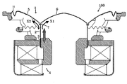
以下、本発明の好ましい実施形態について、図面を参照して具体的に説明するが、本発明はこれらの実施形態には限定されない。図1は、本発明の好ましい実施形態によるスピーカー100の概略断面図である。図2は、スピーカー100の振動板1の要部拡大図である。スピーカー100は、振動板1と、振動板1に接着されるボイスコイルボビン2と、ボイスコイルボビン2の下端部に巻回されたボイスコイル3とを有する。ボイスコイル3は、磁気回路4の磁気ギャップに配され、入力信号に応じて磁気ギャップ内を変位することにより振動板1を駆動する。
Hereinafter, preferred embodiments of the present invention will be specifically described with reference to the drawings. However, the present invention is not limited to these embodiments. FIG. 1 is a schematic cross-sectional view of a
振動板1は、第1振動板部分5と、第1振動板部分5と一体成形された第2振動板部分6とを有する。必要に応じて、振動板1は、第1振動板部分5と一体成形されたエッジ部分11を含む(エッジ部分11は一体成形されていなくてもよい)。第1振動板部分5は、コーン型振動板を形成しており、振動板1の外周部分を形成する。第2振動板部分6は、ドーム型振動板を形成しており(ダストキャプとしての機能を有していてもよい)、振動板1の内周部分を形成する。第1振動板部分5と第2振動板部分6とが一体成形されることにより、第1振動板部分5と第2振動板部分6との結合部において、ボイスコイルボビン2の振動をよりスムーズに(反射することなく)伝達できるので、伝達ロスを防止できる。振動板1は、ボイスコイルボビン2が接着剤によって取り付けられる取付部7をさらに有する。取付部7は、振動板1(具体的には、第1振動板部分5と第2振動板部分6との結合部)の背面側に突出するように設けられている。背面側とは、振動板1のボイスコイルボビン2が接着される側である。また、結合部とは、第1振動板部分5と第2振動板部分6とが結合している部分およびその近傍を意味する。言い換えると、結合部は、振動板1の曲面が凹状から凸状に変化する位置及びその近傍である。振動板1の表面側ではなく背面側に取付部7を突出させているので、取付部7を形成するために第1振動板部分5および第2振動板部分6に折り曲げ部を形成する必要がない。そのため、振動板1の表面側には取付部7が露出しないので、振動板1の美感がきわめて優れたものになる。
The
取付部7は、第1振動板部分5および第2振動板部分6に一体成形されている。一体成形されているので、製造行程が簡素化され、かつ、取付部7が第1振動板部分5および第2振動板部分6から剥離することを防止できる。取付部7は、第1振動板部分5から背面側に延設された第1延設部8と、第2振動板部分6から背面側に延設された第2延設部9とを含み、第1延設部8および第2延設部9との間にボビン接着溝10が規定されている。第1延設部8および第2延設部9の厚みは、好ましくは、0.5〜20mmである。0.5mmより小さければ接着強度が不十分であり、20mm以上であれば第1振動板部分5と第2振動板部分6との結合部の重量が増加しすぎ、音圧が低下するからである。取付部7のボビン接着溝10にボイスコイルボビン2の一端が挿入され、第1および第2延設部によって挟み込まれた状態でボイスコイルボビン2が接着される。ここで、ボイスコイルボビン2の一端は第1振動板部分5および第2振動板部分6に当接しているので、ボイスコイルボビン2の振動は、第1および第2延設部を介さずに直接、第1振動板部分5および第2振動板部分6に伝達される。しかも、先述の通り、第1振動板部分5および第2振動板部分6は、折曲げ部が形成されていないので、振動を反射させる面を有さない。そのため、ボイスコイルボビン2の振動は、図1のX1およびX2に示す通り、第1振動板部分5および第2振動板部分6において、反射されることなく伝達される。
The attachment portion 7 is integrally formed with the
第1振動板部分5および第2振動板部分6は、基材に熱硬化性樹脂が含浸されてなる。熱硬化性樹脂は、任意の適切な熱硬化性樹脂が採用され得るが、好ましくは、不飽和ポリエステルである。硬化速度が速く、硬化温度が低いので製造が容易であり、かつ、優れた内部損失を有する第1振動板部分5および第2振動板部分6が得られるからである。
The
基材は、用途および目的に応じて、任意の適切な織布または不織布が採用され得る。織布または不織布単独であってもよく、複数の不織布を有する積層体、あるいは織布と不織布との積層体であってもよい。不織布としては、代表的には、パラ型アラミド繊維、メタ型アラミド繊維、レーヨン繊維、コットン繊維、超高強力ポリエチレン繊維、ポリアリレート系繊維などが挙げられる。織布としては、ポリ(トリメチレンテレフタレート)、ポリエチレンナフタレート(PEN)繊維などが挙げられる。 Any appropriate woven fabric or non-woven fabric may be adopted as the substrate depending on the application and purpose. A woven fabric or a nonwoven fabric may be used alone, or a laminate having a plurality of nonwoven fabrics, or a laminate of a woven fabric and a nonwoven fabric. Typical examples of the nonwoven fabric include para-type aramid fiber, meta-type aramid fiber, rayon fiber, cotton fiber, ultra-high strength polyethylene fiber, and polyarylate fiber. Examples of the woven fabric include poly (trimethylene terephthalate) and polyethylene naphthalate (PEN) fibers.
取付部7(第1延設部8および第2延設部9)は、樹脂によって成形されている。好ましくは、取付部7は、第1振動板部分5および第2振動板部分6に用いられる熱硬化性樹脂が硬化することによって成形されている。すなわち、取付部7は、好ましくは不飽和ポリエステルによって成形されている。硬化速度が速く、硬化温度が低いので製造が容易であり、かつ、優れた内部損失を有する取付部が得られるからである。詳細は後述するが、取付部7は、第1振動板部分5および第2振動板部分6の基材に熱硬化性樹脂が含浸されると同時に、金型の取付部7の形状部分に熱硬化性樹脂が滴下され、硬化されるので、製造がきわめて簡素化される。さらに、取付部7は熱硬化性樹脂のみによって成形されているので、基材に熱硬化性樹脂が含浸されてなる第1振動板部分5および第2振動板部分6と比べて内部損失が高い。例えば、基材がPEN繊維であり、熱硬化性樹脂が不飽和ポリエステルである場合には、取付部7と、第1振動板部分5(および第2振動板部分6)との内部損失の比は3:1〜1.2:1となる(取付部7の内部損失は0.3〜0.6であり、第1振動板部分5および第2振動板部分6の内部損失は0.1〜0.5である)。従って、ボイスコイルボビン2の(ボイスコイルボビン2に対して)垂直方向の振動は、内部損失の高い取付部7によって減衰され、第1振動板部分5および第2振動板部分6には伝達されない。そのため、ボイスコイルボビン2の垂直方向の振動によって、歪みまたはノイズが発生することを防止でき、S/N比を改善できる。
The attachment part 7 (the
次にスピーカー振動板1の製造方法について、図3を参照して説明する。基材301aは、供給装置301にロール状に巻かれて準備され、工程の流れに応じて供給装置301から送り出される。成形時の変形を防止するために、送り出された基材301aの送り方向に対する両側部がクランプ302により移動可能に支持される。
Next, a method for manufacturing the
次いで、熱硬化性樹脂が、樹脂供給ノズル303aから基材301aの第1振動板部分5および第2振動板部分6に選択的に供給される。
Next, the thermosetting resin is selectively supplied from the
次いで、熱硬化性樹脂が供給された基材301aを、振動板1の形状の上側金型304aおよび下側金型304bを用いて熱プレスする。図4は、上側金型304aおよび下側金型304bを示す概略断面図である。上側金型304aは振動板1の表面(第1振動板部分5および第2振動板部分6)の形状を有しており、下側金型304bは振動板1の背面(第1振動板部分5、第2振動板部分6および取付部7)の形状を有している。その結果、熱硬化性樹脂が圧延により基材301aの第1振動板部分および第2振動板部分に含浸されおよび硬化して、第1振動板部分5および第2振動板部分6が形成され、同時に、下側金型304bの取付部7の形状部分に供給された熱硬化性樹脂が硬化され、取付部7が形成される。下側金型304bのみが取付部7の形状を有しているので、振動板1の背面側に取付部7が成形される。最後に、型抜きと外周切断が行われ、振動板1が得られる。
Next, the
なお、熱プレスの条件(例えば、金型温度、プレス圧力、プレス時間、金型クリアランス)は、目的や用いる不織布基材に応じて、任意の適切な条件が採用され得る。代表的には、金型温度は100〜130℃、加熱時間は0.5〜3分間、プレス時の圧力は15〜25kg/cm2、金型クリアランス(得られるスピーカー用部材の厚みに対応する)は0.1〜0.3mmである。 In addition, arbitrary appropriate conditions can be employ | adopted for the conditions (for example, die temperature, press pressure, press time, die clearance) of hot press according to the objective and the nonwoven fabric base material to be used. Typically, the mold temperature is 100 to 130 ° C., the heating time is 0.5 to 3 minutes, the pressing pressure is 15 to 25 kg / cm 2 , and the mold clearance (corresponding to the thickness of the obtained speaker member). ) Is 0.1 to 0.3 mm.
以下、実施例により本発明を具体的に説明するが、本発明はこれら実施例には限定されない。なお、特に示さない限り、実施例中の部およびパーセントは重量基準である。 EXAMPLES Hereinafter, although an Example demonstrates this invention concretely, this invention is not limited to these Examples. Unless otherwise indicated, parts and percentages in the examples are based on weight.
下記の組成を有する不飽和ポリエステル溶液を調製した:
不飽和ポリエステル樹脂(日本触媒(株)製;N350L) :100(部)
低収縮化剤(日本油脂(株);モディパーS501) :5
パーオクタO(日本油脂(株)) :1.3
一方、表側にポリエチレンナフタレート(PEN)繊維の撚りのない平織り(帝人製 糸番手1100×1100(dtex) 密度17×17(本/inch) 目付け166g/m2)にメラミン樹脂5部を含浸、乾燥した織布とテクノーラ不織布(目付け:60g/m2)を15cm角に切断したものを2層積層して基材とする。約20cm角のステンレス板の中央に直径約16cmの円形の穴を開けた冶具をクランプ゜とし、このクランプ2枚の間に積層した基材を挟んだ後、調合した上記の不飽和ポリエステル溶液(約5g)をクランプした基材の中央付近に滴下する。図4の振動板形状のマッチドダイ金型で130℃で30秒間成形することにより口径16cm、厚さ0.35mmの振動板を得た。取付部7は下側金型のみに掘り込みが設けてあるため、振動板1の背面側のみに不飽和ポリエステル樹脂が硬化して形成される。
An unsaturated polyester solution having the following composition was prepared:
Unsaturated polyester resin (Nippon Shokubai Co., Ltd .; N350L): 100 (parts)
Low shrinkage agent (Nippon Yushi Co., Ltd .; Modiper S501): 5
Perocta O (Nippon Yushi Co., Ltd.): 1.3
On the other hand, a plain weave without twist of polyethylene naphthalate (PEN) fiber (Teijin yarn count 1100 × 1100 (dtex) density 17 × 17 (lines / inch) basis weight 166 g / m2) impregnated with 5 parts of melamine resin and dried Two layers of the woven fabric and Technora nonwoven fabric (weight per unit: 60 g / m 2) cut into 15 cm square are laminated to form a substrate. A jig having a circular hole with a diameter of about 16 cm in the center of an about 20 cm square stainless steel plate is used as a clamp, and the laminated base material is sandwiched between the two clamps. About 5 g) is dropped near the center of the clamped substrate. A diaphragm with a diameter of 16 cm and a thickness of 0.35 mm was obtained by molding at 130 ° C. for 30 seconds with the diaphragm-shaped matched die mold of FIG. Since the attachment portion 7 is provided with an excavation only in the lower mold, the unsaturated polyester resin is cured and formed only on the back side of the
得られた振動板について、通常の方法で、取付部7および第1振動板部分5(第2振動板部分6)のヤング率および内部損失を測定した。測定結果を下記の表1に示す。

表1に示す通り、取付部7の内部損失は、第1振動板部分5(および第2振動板部分6)の内部損失の2.25倍である。そのため、ボイスコイルボビンの垂直方向の振動は内部損失の高い取付部7によって減衰され、第1振動板部分5(および第2振動板部分6)には伝達されにくい。従って、歪みの発生を防止できる。以上、本発明の好ましい実施形態について説明したが、本発明はこれらの実施形態には限定されない。 As shown in Table 1, the internal loss of the attachment portion 7 is 2.25 times the internal loss of the first diaphragm portion 5 (and the second diaphragm portion 6). Therefore, the vibration in the vertical direction of the voice coil bobbin is attenuated by the mounting portion 7 having a high internal loss, and is not easily transmitted to the first diaphragm portion 5 (and the second diaphragm portion 6). Therefore, the occurrence of distortion can be prevented. As mentioned above, although preferable embodiment of this invention was described, this invention is not limited to these embodiment.
本発明のスピーカー振動板は、様々な用途(家庭用、車載用)に用いられるスピーカーに好適に適用され得る。さらに、特に低周波数領域を再生するウーファー、または高周波数領域を再生するツィータ等、特性に問わず任意のスピーカーに適用され得る。 The speaker diaphragm of the present invention can be suitably applied to speakers used for various purposes (for home use and in-vehicle use). Furthermore, the present invention can be applied to any speaker regardless of characteristics, such as a woofer that reproduces a low frequency region or a tweeter that reproduces a high frequency region.
1 振動板
5 第1振動板部分
6 第2振動板部分
7 取付部
DESCRIPTION OF
Claims (4)
該第1振動板部分および該第2振動板部分が、基材に熱硬化性樹脂が含浸されてなり、該取付部が、該熱硬化性樹脂が硬化されて成形されている、スピーカー振動板。 A first diaphragm portion, a second diaphragm portion formed integrally with the first diaphragm portion, and a back side of a coupling portion between the first diaphragm portion and the second diaphragm portion are provided to protrude. An attachment portion to which one end of the voice coil bobbin is attached,
A speaker diaphragm in which the first diaphragm portion and the second diaphragm portion are formed by impregnating a base material with a thermosetting resin, and the mounting portion is formed by curing the thermosetting resin. .
金型の、ボイスコイルボビンの一端が接着される取付部を形成する部分に該熱硬化性樹脂を供給する行程と、
該含浸した熱硬化性樹脂を硬化させて該第1振動板部分および該第2振動板部分を形成すると同時に、該金型の取付部を形成する部分に供給された熱硬化性樹脂を硬化させて該取付部を形成する行程とを含む、スピーカー振動板の製造方法。 A step of impregnating a portion to be the first diaphragm portion and the second diaphragm portion of the base material with a thermosetting resin;
Supplying the thermosetting resin to a portion of the mold that forms a mounting portion to which one end of the voice coil bobbin is bonded;
The impregnated thermosetting resin is cured to form the first diaphragm portion and the second diaphragm portion, and at the same time, the thermosetting resin supplied to the portion forming the mounting portion of the mold is cured. And a step of forming the mounting portion.
Priority Applications (5)
| Application Number | Priority Date | Filing Date | Title |
|---|---|---|---|
| JP2004273250A JP3846497B2 (en) | 2004-09-21 | 2004-09-21 | Speaker diaphragm and speaker with the same |
| US11/183,033 US7567684B2 (en) | 2004-09-21 | 2005-07-15 | Speaker diaphragm and speaker using the same |
| AT05016127T ATE488968T1 (en) | 2004-09-21 | 2005-07-25 | SPEAKER MEMBRANE AND LOUDSPEAKER USING SUCH A MEMBRANE |
| DE602005024751T DE602005024751D1 (en) | 2004-09-21 | 2005-07-25 | Speaker diaphragm and speakers with application of such a Menbran |
| EP05016127A EP1638365B1 (en) | 2004-09-21 | 2005-07-25 | Speaker diaphragm and speaker using the same |
Applications Claiming Priority (1)
| Application Number | Priority Date | Filing Date | Title |
|---|---|---|---|
| JP2004273250A JP3846497B2 (en) | 2004-09-21 | 2004-09-21 | Speaker diaphragm and speaker with the same |
Publications (3)
| Publication Number | Publication Date |
|---|---|
| JP2006093804A JP2006093804A (en) | 2006-04-06 |
| JP2006093804A5 JP2006093804A5 (en) | 2006-07-20 |
| JP3846497B2 true JP3846497B2 (en) | 2006-11-15 |
Family
ID=35432161
Family Applications (1)
| Application Number | Title | Priority Date | Filing Date |
|---|---|---|---|
| JP2004273250A Expired - Fee Related JP3846497B2 (en) | 2004-09-21 | 2004-09-21 | Speaker diaphragm and speaker with the same |
Country Status (5)
| Country | Link |
|---|---|
| US (1) | US7567684B2 (en) |
| EP (1) | EP1638365B1 (en) |
| JP (1) | JP3846497B2 (en) |
| AT (1) | ATE488968T1 (en) |
| DE (1) | DE602005024751D1 (en) |
Cited By (1)
| Publication number | Priority date | Publication date | Assignee | Title |
|---|---|---|---|---|
| US7835538B2 (en) | 2008-02-27 | 2010-11-16 | Onkyo Corporation | Loudspeaker |
Families Citing this family (14)
| Publication number | Priority date | Publication date | Assignee | Title |
|---|---|---|---|---|
| ATE394894T1 (en) * | 2003-08-19 | 2008-05-15 | Matsushita Electric Ind Co Ltd | SPEAKER |
| JP2005080098A (en) * | 2003-09-02 | 2005-03-24 | Pioneer Electronic Corp | Diaphragm for speaker and speaker having the same |
| EP1950998B1 (en) | 2007-01-29 | 2014-03-26 | Sony Corporation | Speaker unit and speaker apparatus |
| CN101909232B (en) * | 2009-06-08 | 2014-08-27 | 富准精密工业(深圳)有限公司 | Sound film and speaker employing same |
| US20120321124A1 (en) * | 2009-06-08 | 2012-12-20 | Hon Hai Precision Industry Co., Ltd. | Diaphragm and micro-electroacoustic device incorporating the same |
| US9277324B2 (en) | 2013-12-19 | 2016-03-01 | Apple Inc. | Three part membrane speaker |
| JP6418556B2 (en) * | 2015-12-17 | 2018-11-07 | オンキヨー株式会社 | Speaker diaphragm, speaker including the same, and method for manufacturing speaker diaphragm |
| US9913042B2 (en) | 2016-06-14 | 2018-03-06 | Bose Corporation | Miniature device having an acoustic diaphragm |
| US10499159B2 (en) | 2017-05-17 | 2019-12-03 | Bose Corporation | Method of fabricating a miniature device having an acoustic diaphragm |
| US10448183B2 (en) | 2017-07-27 | 2019-10-15 | Bose Corporation | Method of fabricating a miniature device having an acoustic diaphragm |
| CN208638586U (en) * | 2018-08-04 | 2019-03-22 | 瑞声科技(新加坡)有限公司 | A kind of loudspeaker |
| US10951991B2 (en) * | 2019-02-27 | 2021-03-16 | Paradigm Electronics Inc. | Loudspeaker |
| CN111872663A (en) * | 2020-07-28 | 2020-11-03 | 泉州泉港聚业工业设计有限公司 | Automatic assembling and bonding device for electronic element |
| US11451909B1 (en) * | 2021-04-01 | 2022-09-20 | Apple Inc. | Vented audio transducer |
Family Cites Families (11)
| Publication number | Priority date | Publication date | Assignee | Title |
|---|---|---|---|---|
| JPS53119023A (en) * | 1977-03-26 | 1978-10-18 | Kenzou Inoue | Moving coil type sound converting vibration plate |
| JPS5634297A (en) * | 1979-08-29 | 1981-04-06 | Kenzo Inoue | Speaker unit |
| JP2804956B2 (en) | 1992-07-15 | 1998-09-30 | 矢崎総業株式会社 | Vehicle operation information collection and analysis system |
| JPH0634397U (en) | 1992-10-01 | 1994-05-06 | 富士通テン株式会社 | Speaker |
| JPH08163694A (en) | 1994-11-30 | 1996-06-21 | Mitsubishi Electric Corp | Integral type loudspeaker diaphragm |
| JP2002125290A (en) | 2000-10-18 | 2002-04-26 | Sony Corp | Loudspeaker device |
| JP4006981B2 (en) | 2001-11-16 | 2007-11-14 | 松下電器産業株式会社 | Speaker |
| JP2003199193A (en) | 2001-12-27 | 2003-07-11 | Pioneer Electronic Corp | Speaker system |
| JP3896900B2 (en) * | 2002-05-28 | 2007-03-22 | ソニー株式会社 | Speaker device |
| EP1429582B1 (en) | 2002-12-09 | 2013-01-16 | Onkyo Corporation | Loudspeaker diaphragm and method for manufacturing the same |
| JP2005026920A (en) | 2003-06-30 | 2005-01-27 | Sony Corp | Speaker diaphragm and speaker |
-
2004
- 2004-09-21 JP JP2004273250A patent/JP3846497B2/en not_active Expired - Fee Related
-
2005
- 2005-07-15 US US11/183,033 patent/US7567684B2/en not_active Expired - Fee Related
- 2005-07-25 AT AT05016127T patent/ATE488968T1/en not_active IP Right Cessation
- 2005-07-25 EP EP05016127A patent/EP1638365B1/en not_active Not-in-force
- 2005-07-25 DE DE602005024751T patent/DE602005024751D1/en active Active
Cited By (1)
| Publication number | Priority date | Publication date | Assignee | Title |
|---|---|---|---|---|
| US7835538B2 (en) | 2008-02-27 | 2010-11-16 | Onkyo Corporation | Loudspeaker |
Also Published As
| Publication number | Publication date |
|---|---|
| EP1638365B1 (en) | 2010-11-17 |
| JP2006093804A (en) | 2006-04-06 |
| US7567684B2 (en) | 2009-07-28 |
| EP1638365A2 (en) | 2006-03-22 |
| US20060062422A1 (en) | 2006-03-23 |
| DE602005024751D1 (en) | 2010-12-30 |
| ATE488968T1 (en) | 2010-12-15 |
| EP1638365A3 (en) | 2007-10-31 |
Similar Documents
| Publication | Publication Date | Title |
|---|---|---|
| EP1638365B1 (en) | Speaker diaphragm and speaker using the same | |
| US7849958B2 (en) | Vibration system part for speaker device and manufacturing method thereof | |
| JP4505690B2 (en) | speaker | |
| JP5037722B2 (en) | Vibration direction converter for speaker device and speaker device | |
| US20060098839A1 (en) | Voice coil device and manufacturing method thereof | |
| JP5254119B2 (en) | speaker | |
| JP4419976B2 (en) | Speaker diaphragm and speaker | |
| JP2001204093A (en) | Speaker component and its manufacturing method | |
| JP2002218593A (en) | Speaker damper and its manufacturing method | |
| JP2009027309A (en) | Speaker diaphragm, speaker using the same and method of manufacturing speaker diaphragm | |
| US20040131221A1 (en) | Speaker surround and method for producing the same | |
| JP2008113275A (en) | Speaker diaphragm and speaker using the same | |
| JP2009021832A (en) | Diaphragm for speaker and speaker using the same | |
| JP3888369B2 (en) | Speaker member and manufacturing method thereof | |
| JP5158374B2 (en) | speaker | |
| JP2005318340A (en) | Diaphragm for speaker and speaker apparatus | |
| CN113498008B (en) | Loudspeaker vibrating reed locally provided with anti-noise layer and manufacturing method thereof | |
| JP2001309489A (en) | Loudspeaker damper and loudspeaker unit using the same | |
| JPH0752996B2 (en) | Vibration plate for speakers | |
| JP3131033B2 (en) | Speaker | |
| JP2009027308A (en) | Speaker diaphragm, speaker using the same and method of manufacturing speaker diaphragm | |
| JP2010011436A (en) | Speaker diaphragm, and electrodynamic loudspeaker using the same | |
| JPH04340899A (en) | Diaphragm for speaker and its manufacture | |
| JP2011217281A (en) | Speaker center holding member, speaker employing the same, and method of manufacturing the speaker center holding member | |
| JP2012070148A (en) | Speaker |
Legal Events
| Date | Code | Title | Description |
|---|---|---|---|
| A521 | Request for written amendment filed |
Free format text: JAPANESE INTERMEDIATE CODE: A523 Effective date: 20060602 |
|
| A871 | Explanation of circumstances concerning accelerated examination |
Free format text: JAPANESE INTERMEDIATE CODE: A871 Effective date: 20060602 |
|
| A975 | Report on accelerated examination |
Free format text: JAPANESE INTERMEDIATE CODE: A971005 Effective date: 20060609 |
|
| A131 | Notification of reasons for refusal |
Free format text: JAPANESE INTERMEDIATE CODE: A131 Effective date: 20060627 |
|
| A521 | Request for written amendment filed |
Free format text: JAPANESE INTERMEDIATE CODE: A523 Effective date: 20060630 |
|
| TRDD | Decision of grant or rejection written | ||
| A01 | Written decision to grant a patent or to grant a registration (utility model) |
Free format text: JAPANESE INTERMEDIATE CODE: A01 Effective date: 20060801 |
|
| A61 | First payment of annual fees (during grant procedure) |
Free format text: JAPANESE INTERMEDIATE CODE: A61 Effective date: 20060814 |
|
| R150 | Certificate of patent or registration of utility model |
Ref document number: 3846497 Country of ref document: JP Free format text: JAPANESE INTERMEDIATE CODE: R150 Free format text: JAPANESE INTERMEDIATE CODE: R150 |
|
| FPAY | Renewal fee payment (event date is renewal date of database) |
Free format text: PAYMENT UNTIL: 20120901 Year of fee payment: 6 |
|
| FPAY | Renewal fee payment (event date is renewal date of database) |
Free format text: PAYMENT UNTIL: 20120901 Year of fee payment: 6 |
|
| FPAY | Renewal fee payment (event date is renewal date of database) |
Free format text: PAYMENT UNTIL: 20150901 Year of fee payment: 9 |
|
| S111 | Request for change of ownership or part of ownership |
Free format text: JAPANESE INTERMEDIATE CODE: R313111 |
|
| FPAY | Renewal fee payment (event date is renewal date of database) |
Free format text: PAYMENT UNTIL: 20150901 Year of fee payment: 9 |
|
| R350 | Written notification of registration of transfer |
Free format text: JAPANESE INTERMEDIATE CODE: R350 |
|
| S531 | Written request for registration of change of domicile |
Free format text: JAPANESE INTERMEDIATE CODE: R313531 |
|
| S533 | Written request for registration of change of name |
Free format text: JAPANESE INTERMEDIATE CODE: R313533 |
|
| R350 | Written notification of registration of transfer |
Free format text: JAPANESE INTERMEDIATE CODE: R350 |
|
| R250 | Receipt of annual fees |
Free format text: JAPANESE INTERMEDIATE CODE: R250 |
|
| S111 | Request for change of ownership or part of ownership |
Free format text: JAPANESE INTERMEDIATE CODE: R313113 |
|
| R350 | Written notification of registration of transfer |
Free format text: JAPANESE INTERMEDIATE CODE: R350 |
|
| LAPS | Cancellation because of no payment of annual fees |