JP3844992B2 - Air conditioner or air purifier - Google Patents
Air conditioner or air purifier Download PDFInfo
- Publication number
- JP3844992B2 JP3844992B2 JP2001325034A JP2001325034A JP3844992B2 JP 3844992 B2 JP3844992 B2 JP 3844992B2 JP 2001325034 A JP2001325034 A JP 2001325034A JP 2001325034 A JP2001325034 A JP 2001325034A JP 3844992 B2 JP3844992 B2 JP 3844992B2
- Authority
- JP
- Japan
- Prior art keywords
- ion
- air
- increase
- blower
- amount
- Prior art date
- Legal status (The legal status is an assumption and is not a legal conclusion. Google has not performed a legal analysis and makes no representation as to the accuracy of the status listed.)
- Expired - Fee Related
Links
Images


Description
【0001】
【発明が属する技術分野】
この発明は負イオンを発生するイオン発生装置を空気調和機又は空気清浄機に組み込んだ事に関する。
【0002】
【従来の技術】
従来より負イオンが人体に対して良い効果をもたらすことは知られており、生理作用の改善や医学療法等に利用されるものである。
また従来例として特公平7−23777号の空気調和機がある。この空気調和機は送風経路に負イオンと正イオンの両方イオンを発生するイオン発生装置を、吸込口にイオンセンサを備え、イオンセンサで測定されたイオン量と予め設定されたイオン量の差に応じて送風ファンの送風量を変化させる事でイオンの発生量を調節していた。
【0003】
【発明が解決しようとする課題】
しかし、このような従来の空気調和機はイオンの発生量を送風ファンの送風量によって予め設定されたイオン量に調節するために使用者は好みに応じて、自らイオンの発生量を増減する事ができないものだった。
【0004】
【問題点を解決するための手段】
この発明はこの点に着目し上記欠点を解決する為、特にその構成を、筐体内に熱交換器と送風ファンを備え、筐体表面に吸込口と吹出口を設け、前記吸込口と熱交換器と送風ファンと吹出口を連通して送風経路を形成し、前記送風ファンの運転で吸込口から吸込んだ室内の空気を熱交換器にて冷却又は加熱した後、吹出口から室内に吹き出すことで室温調節を行うと共に、前記送風経路又は吹出口近傍にイオン発生装置を設け、吹出口より吹出される空気にて室内に負イオンを拡散する空気調和機に於いて、前記空気調和機の運転操作を行う操作部と負イオンの発生量を表示する表示部を備え、前記操作部には少なくともイオン発生装置の運転停止を行うイオン運転スイッチと負イオンの発生量を増減するイオン増減スイッチを設け、前記表示部には複数のイオンランプを備え、通常運転時にはイオンセンサの値に応じて順次イオンランプが点灯し、前記イオン増減スイッチの操作によるイオン増加運転の場合には、中央から端部に向けてイオンランプを順次点滅させイオンの増加を動的に表現する制御装置を設けた空気調和機であり。
【0005】
また筐体内に空気清浄フィルタと送風ファンを備え、筐体表面に吸込口と吹出口を設け、前記吸込口と空気清浄フィルタと送風ファンと吹出口を連通して送風経路を形成し、前記送風ファンの運転で吸込口から吸込んだ室内の空気を空気清浄フィルタにて浄化した後、吹出口から室内に吹き出すことで空気清浄を行うと共に、前記送風経路又は吹出口近傍にイオン発生装置を設け、吹出口より吹出される空気にて室内に負イオンを拡散する空気清浄機に於いて、前記空気清浄機の運転操作を行う操作部と負イオンの発生量を表示する表示部を備え、前記操作部には少なくともイオン発生装置の運転停止を行うイオン運転スイッチと負イオンの発生量を増減するイオン増減スイッチを設け、前記表示部には複数のイオンランプを備え、通常運転時にはイオンセンサの値に応じて順次イオンランプが点灯し、前記イオン増減スイッチの操作によるイオン増加運転の場合には、中央から端部に向けてイオンランプを順次点滅させイオンの増加を動的に表現する制御装置を設けた空気清浄機であり。
【0006】
前記イオン増減スイッチにて負イオンの増加操作を行った場合には、前記イオン発生装置はイオンの発生量を増加すると共に前記表示装置にてイオン発生量の増加を表示し、所定時間経過後には増加前のイオン発生量に自動的に戻るイオン発生量調整手段を設けた空気調和機又は空気清浄機。
【0007】
【発明の実施の形態】
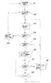
図6のS2にて空気調和機運転中でイオン発生装置20運転中であればS3に進み、イオンランプ38を負イオンの発生量に応じて左側から順次点灯する通常表示を行う。S2にてイオン発生装置20が停止していれば、そのままS1に戻り運転を続ける。
次にS4にてイオン運転スイッチ31が押圧された場合は、S10にて負イオンの発生を停止してイオンランプ38を消灯しS1に戻る。またイオン運転スイッチ31の押圧がない場合にはS5に進む。
【0008】
S5ではイオン増減スイッチ32の押圧を判断し、押圧された場合にはS6にて入力電力制御回路44によてイオン発生回路42に送る電力を、通常時80%であったものを100%に増加することで放射電極14から発生する負イオンを増量すると共に、イオンランプ38の増量表示行い、タイマ49をスタートする。
またイオン増減スイッチ32の押圧がない場合にはS3に戻り通常のイオン発生運転を続ける。
【0009】
S7ではイオン増減スイッチ32の再度の押圧を判断し、押圧の場合はS9にてイオン発生回路42の電力を80%にすると共にイオンランプ38を通常表示に切換えS3に戻る。イオン増減スイッチ32の押圧がない状態で20分間経過すれば自動的にS8からS9に進みS3に戻って通常運転を継続するものである。
【0010】
従って、使用者は負イオンの発生量をその時の気分や体調、好みに応じて増加する事ができるようにしたことで、使用者自身で気分の回復や体調管理等を普通の生活をしながら容易に調節することができ、極めて使用勝手が良いものである。
又イオンランプ38を使用した動的な表示により負イオンの増量状態を使用者にわかりやすく知らしめる事ができるものである。
【0011】
又負イオン発生量増加後には必要に応じて負イオンの発生量を増加前の通常の発生量に減じる事が簡単にできる様になると共に、負イオン増量開始から所定時間後には自動的に通常の発生量に戻るので、長時間負イオンが過剰に発生する事で人体に害を及ぼしたり、器具周囲の壁等にホコリが多量に付着する事を防止するものである。
【0012】
【実施例】
以下この発明の実施の形態を図面をもとに説明すれば、1はセパレート式空気調和機の室内ユニットで、本体ケーシング2と前方の前面カバー3によって筐体を形成し、前記前面カバー3の正面中央と上部に横長スリット状の吸込口4を有するオープンパネル5を備え、このパネル5は前面カバー3の上部左右に設けた軸(図示せず)を支点として前方へ開閉自在に取付られ、且つ前記軸に着脱自在に設けられている。
【0013】
前記吸込口4下方から前面カバー3底面には横長の吹出口6を設け、また前面カバー3上面には前記吸込口4で不足する開口面積を補うために上部吸込口7を設けている。
前記吸込口4・7の内側には樹脂材料から成る網目状のプレフィルタ8が取り付けられ吸込口4・7から吸い込まれた空気中のホコリを取り除くものである。
【0014】
前記プレフィルタ8の内側には横長で多段に屈曲され、最上部から後部に向かって断面山型に配置されると共に前面に沿って前記吹出口6上方まで位置するフィンチューブ式の熱交換器9を設け、この熱交換器9の後部内側にはクロスフロー式の送風ファン10を配置している。
この送風ファン10は通常運転時約750〜1,100rpmの範囲で多段階の回転数で回転し、前記吸込口4・7から室内空気を吸い込み吹出口6より熱交換された空気を吹き出すものである。
【0015】
前記熱交換器9の下方には樹脂の発泡材で一体成形されたドレーン皿11を設け、結露水を受けると共に前記送風ファン10の送風を吹出口6へ導くエアーガイドの機能を兼ねるものである。
【0016】
12は前記オープンパネル5の吸込口4下方の前面中央に備えた表示部で、ダイオード等のランプ類が多数設けられ、このランプ類により運転状態をわかりやすく表示するものである。
【0017】
前記表示部12の右側に備えた穴部13の中心には、前方に向けて針状の放射電極14が設けられ、この放射電極14が直流の高電圧になることで負イオンが発生し、吹出口6からの送風に乗り室内に拡散するものである。
【0018】
15は前記吹出口6内に備えた水平ルーバで、空気調和機の運転停止時には上下2枚の羽根にて吹出口6を塞ぎ、運転時には回動により上下に吹出し風の方向を調整するものであり、16は前記本体ケーシング2に左右方向に回動自在に設けた左右風向板である。
【0019】
17は集塵ユニットで約+2kvの直流電源に接続されたアルミ板に多数の穴18aを設けた放電対極18と、この穴18aの略中心に向かって針先を位置させた針状電極19aで形成され約−2kvの直流電源に接続された放電極19とで構成し、空気中の目に見えない塵やタバコの煙を前記放電極19で帯電し放電対極18にて捕捉するものであり、前記熱交換器9と前面パネル3の間の上部空間に取り付けられるものである。
【0020】
20はイオン発生装置で前記穴部13背面のオープンパネル5やドレーン皿11等に固定され、内部には穴部13に対向して位置する前記放射電極14とこの放射電極14を直流の高電圧にする回路部品等を備えるものである。
【0021】
前記放射電極14は針状で−8kv程の電位がかけられ負イオンを発生するもので、針先は鋭利で有るため前面の穴部13は一個一個が指先の入らない大きさに設けられる。また放射電極14はイオン発生装置20内の基板21から穴部13に向かって3本平行にけられている。
22は前記吸込口4から吸込まれた空気が熱交換器9、送風ファン10を経由して吹出口6より室内に吹出す送風経路。
【0022】
図4をもとに制御回路のブロック図を説明すれば、23は空気調和機の運転停止や前記イオン発生装置20や静電式集塵装置24の制御等空気調和機全体の制御を行うマイクロコンピュータ等の制御装置である。
【0023】
25はワイヤレスリモコン26の受信装置で、このワイヤレスリモコン26からの信号を前記制御装置23に中継するものである。
27は前記ワイヤレスリモコン26の操作部で、運転スイッチ28や冷暖房の切替等を行うモードスイッチ29やタイマスイッチ30と前記イオン発生装置20の運転停止を行うイオン運転スイッチ31や負イオン発生時の押圧で負イオンの発生量を増減するイオン増減スイッチ32等のスイッチ類を備えている。
前記のスイッチ類はスイッチ動作後、ボタンを離すと初期状態に戻るモーメンタリ式のスイッチから構成している。
【0024】
33は空気中のイオン濃度を測定するイオンセンサで、前記吸込口4に設けられイオンの発生状態を検知するものである。
34は前記吸込口4と熱交換器9の間に設けられた室温センサで、吸込空気の温度を測定する。
【0025】
35は前記熱交換器9の銅管又はアルミフィン等に取り付けられた熱交センサーで、熱交換器9の温度を測定するものであり、前記イオンセンサ33や室温センサ34と共に制御装置23の入力側に接続されている。
前記制御装置23の出力側には表示部12が接続され、この表示部12には空気調和機運転時に点灯する運転ランプ36や、タイマ運転時に点灯するタイマランプ37、イオン発生時に点灯又は点滅するイオンランプ38が設けられている。
【0026】
39は前記送風ファン10のファンモータ、40は室外機(図示せず)の室外側制御装置、41は前記吹出口6に備えた風向変更用の前記水平ルーバ15を回動するルーバーモータで、前記制御装置23の出力側にそれぞれ接続されている。
【0027】
42は前記イオン発生装置20に備えたイオン発生回路で、電源43との間に設けた入力電力制御回路44に備えたフォトカプラやソリッドステートリレーにて交流波形の一部を削除することで、イオン発生回路42へ供給する電力の調整を行うものである。
前記静電式集塵装置24は集塵ユニット17と集塵回路45と、この集塵回路45と電源46の間をON−OFFするリレー47を備え、前記制御装置23の出力側に接続されている。
【0028】
前記電源43では交流100v50Hz又は60Hzの商用電源が、入力電力制御回路44によって約70〜100vの間に実行電力を調整して前記イオン発生回路42に供給し、イオン発生回路42では前記放射電極14が直流約−5〜8kvの電位になるように昇圧することで5,000〜10,000個/ccの負イオンを発生し、室内に放出するものである。
【0029】
また前記静電式集塵装置24は交流100vの電源を集塵回路45にて約+2kvと約−2kvの直流に変換して前記集塵ユニット17に供給するもので、前記リレー47によって制御装置23にて運転、停止を行うものである。
【0030】
48は前記制御装置23内に備えたイオン発生量調整手段で、前記イオン増減スイッチ32の操作によって入力電力制御回路44にて通常時70〜80%の実行電力でイオン発生回路42に電源を供給しているものを、100%の電力に切り換える事で放射電極14から発生する負イオンの発生量を通常運転時の約20〜40%増加すると共に、前記制御装置23内に備えたタイマ49をスタートさせ、この実施例では20分間を計時し、イオン増加状態の運転が20分継続した場合には、イオン増加運転により弊害が発生する事を防止するために自動的にイオンの発生量を通常運転に戻すものである。
【0031】
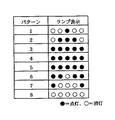
前記イオンランプ38は5個のダイオードが水平に連なるものであり、イオン発生装置20が運転していない場合にはランプ38は消灯し、通常運転時にはイオンセンサ33の値に応じて左側から順次ランプが点灯するものであり、イオン増加運転の場合には中央から左右に向けてランプを順次点灯させる事で、イオンの増加を動的に表現するとてもわかりやすい表示が行われるものである。
【0032】
前記イオン増加運転時のランプ表示を詳しく説明すれば、まずイオン増加運転開始時には5個のイオンランプ38が全て点灯0.5秒間・全て消灯を0.5秒間を3回繰り返して点滅表示を行う事でイオン増加運転の開始を表示する。
次にイオン増加運転中は図5のに示す様に0.5秒間隔で順次バターン1から8まで順番に表示する事を繰り返す動的なランプ表示により、イオンの増量を使用者にわかりやすく表現するものである。
【0033】
次にイオン増加運転終了時には全てのランプをいったん0.5秒間点灯後、0.5秒間消灯する事でイオン増加運転の終了を表示した後、前記の通常運転時の表示に戻るものである。
【0034】
作動について説明すれば、ワイヤレスリモコン26の運転スイッチ28を押圧すれば送風ファン10が回転を始めると共に室外ユニットに備えた圧縮機が回転し冷凍回路内の冷媒が循環する事で冷房運転時には熱交換器9は低温になり、暖房運転時には熱交換器9は高温になり、吸込口4から吸込まれた室内の空気が熱交換され吹出口6より室内吹出される事で室内の空気調和が行われる。
【0035】
これと連動してイオン発生装置20も通常運転を開始し、放射電極14が高電圧になることで負イオンが発生し、放射電極14から発生した負イオンは吹出口6から吹出される送風に乗って勢いよく室内にまんべんなく拡散されるものである。
【0036】
図6のフローチャートによってイオン運転スイッチ31とイオン増減スイッチ32の作動について説明すれば、S2にて空気調和機運転中でイオン発生装置20運転中であればS3に進み、イオンランプ38を負イオンの発生量に応じて左側から順次点灯する通常表示を行う。S2にてイオン発生装置20が停止していれば、そのままS1に戻り運転を続ける。
【0037】
次にS4にてイオン運転スイッチ31が押圧された場合は、S10にて負イオンの発生を停止してイオンランプ38を消灯しS1に戻る。またイオン運転スイッチ31の押圧がない場合にはS5に進む。
【0038】
S5ではイオン増減スイッチ32の押圧を判断し、押圧された場合にはS6にて入力電力制御回路44によてイオン発生回路42に送る電力を、通常時80%であったものを100%に増加することで放射電極14から発生する負イオンを増量すると共に、イオンランプ38の増量表示行い、タイマ49をスタートする。
またイオン増減スイッチ32の押圧がない場合にはS3に戻り通常のイオン発生運転を続ける。
【0039】
S7ではイオン増減スイッチ32の再度の押圧を判断し、押圧の場合はS9にてイオン発生回路42の電力を80%にすると共にイオンランプ38を通常表示に切換えS3に戻る。イオン増減スイッチ32の押圧がない状態で20分間経過すれば自動的にS8からS9に進みS3に戻って通常運転を継続するものである。
【0040】
この一実施例では空気調和機の説明を行ったが、熱交換器9に換え活性炭フィルターを使用すれば空気清浄機にそのまま応用できるものであり、またこの一実施例では操作部27をワイヤレスリモコン26に設けているがユニットに一体に設けても良いものである。
【0041】
このように使用者は負イオンの発生量をその時の気分や体調、好みに応じて増加する事ができるようにしたことで、使用者自身で気分の回復や体調管理等を普通の生活をしながら容易に調節することができ、極めて使用勝手が良いものである。
又イオンランプ38を使用した動的な表示により負イオンの増量状態を使用者にわかりやすく知らしめる事ができるものである。
【0042】
又負イオン発生量増加後には必要に応じて負イオンの発生量を増加前の通常の発生量に減じる事が簡単にできる様になると共に、負イオン増量開始から所定時間後には自動的に通常の発生量に戻るので、長時間負イオンが過剰に発生する事で人体に害を及ぼしたり、器具周囲の壁等にホコリが多量に付着する事を防止するものである。
【0043】
又イオン増減スイッチ32はモーメンタリスイッチで構成したのでイオン増加運転後自動的に通常運転に戻った場合でも、1回の押圧で簡単に再度のイオン増加運転ができるものである。
【0044】
【発明の効果】
以上のようにこの発明によれば、室内の良好な空気調和を得ることは勿論、使用者はその時の気分や体調、好みに応じて負イオンの発生量を増加する事ができるようにしたことで、使用者自身で気分の回復や体調管理等を普通の生活をしながら容易に調節することができ、極めて使用勝手が良いものである。
又イオンランプを使用した動的な表示により負イオンの増量状態を使用者にわかりやすく知らしめる事ができるものである。
又負イオン発生量増加後には必要に応じて負イオンの発生量を増加前の通常の発生量に減じる事が簡単にできる様になると共に、負イオン増量開始から所定時間後には自動的に通常の発生量に戻るので、長時間負イオンが過剰に発生する事で人体に害を及ぼしたり、器具周囲の壁等にホコリが多量に付着する事を防止でき、安心して使用できるものである。
【図面の簡単な説明】
【図1】この発明の一実施例正面図。
【図2】同構造を簡略した側面の拡大断面図。
【図3】同集塵ユニット11の要部断面図。
【図4】同制御回路の略図。
【図5】同イオンランプ38の表示の説明図。
【図6】同フローチャート図。
【符号の説明】
1 室内ユニット
6 吹出口
9 送風ファン
12 表示部
20 イオン発生装置
27 操作部
31 イオン運転スイッチ
32 イオン増減スイッチ
48 イオン発生量調整手段[0001]
[Technical field to which the invention belongs]
The present invention relates to the incorporation of an ion generator that generates negative ions into an air conditioner or an air purifier.
[0002]
[Prior art]
Conventionally, it has been known that negative ions have a good effect on the human body, and it is used for improving physiological action and medical therapy.
As a conventional example, there is an air conditioner of Japanese Patent Publication No. 7-23777. This air conditioner has an ion generator that generates both negative ions and positive ions in the air flow path, and an ion sensor in the suction port. The difference between the ion amount measured by the ion sensor and a preset ion amount is obtained. Accordingly, the amount of ions generated was adjusted by changing the amount of air blown by the blower fan.
[0003]
[Problems to be solved by the invention]
However, in such a conventional air conditioner, in order to adjust the ion generation amount to a preset ion amount by the air blowing amount of the blower fan, the user can increase or decrease the ion generation amount according to his / her preference. It was something that could not be done.
[0004]
[Means for solving problems]
The present invention pays attention to this point and solves the above-mentioned drawbacks. In particular, the structure is provided with a heat exchanger and a blower fan in the housing, a suction port and a blower port are provided on the surface of the housing, and heat exchange with the suction port is performed. A ventilation passage is formed by communicating a ventilator, a blower fan, and a blower outlet, and after the indoor air sucked from the suction port is cooled or heated by the heat exchanger in the operation of the blower fan, the blower blows out into the room from the blower outlet. In an air conditioner that adjusts the room temperature and provides an ion generator near the air blowing path or the outlet, and diffuses negative ions into the room with the air blown from the outlet, the operation of the air conditioner An operation unit for performing an operation and a display unit for displaying the amount of generated negative ions are provided, and at least an ion operation switch for stopping the operation of the ion generator and an ion increasing / decreasing switch for increasing / decreasing the amount of generated negative ions are provided in the operation unit. The table The unit is equipped with a plurality of ion lamps, and in normal operation, the ion lamps are turned on sequentially according to the value of the ion sensor. In the case of ion increase operation by operation of the ion increase / decrease switch, the ions are directed from the center toward the end. It is an air conditioner equipped with a control device that dynamically flashes the lamp and dynamically expresses the increase in ions .
[0005]
In addition, an air purifying filter and a blower fan are provided in the housing, a suction port and an air outlet are provided on the surface of the housing, and an air passage is formed by communicating the suction port, the air purifying filter, the air fan and the air outlet, and the air blowing After purifying the indoor air sucked from the suction port by the fan operation with an air purifying filter, and performing air purification by blowing it out from the air outlet into the room, an ion generator is provided near the air blowing path or the air outlet, In an air purifier that diffuses negative ions into the room with air blown out from an air outlet, the air purifier includes an operation unit that operates the air purifier and a display unit that displays the amount of negative ions generated. parts in the provided ion decrease switch for increasing or decreasing ion operation switch and the amount of generated negative ions stopping the operation of at least the ion generating device, comprising a plurality of ion lamp on the display unit, a normal operation The ion lamps are turned on sequentially according to the value of the ion sensor, and in the case of the ion increase operation by the operation of the ion increase / decrease switch, the ion lamp flashes sequentially from the center toward the end portion to dynamically increase the ions. It is an air cleaner provided with a control device expressed in
[0006]
When negative ion increase operation is performed with the ion increase / decrease switch, the ion generator increases the amount of ions generated and displays the increase in the amount of ions generated on the display device. An air conditioner or an air cleaner provided with ion generation amount adjusting means that automatically returns to the ion generation amount before the increase.
[0007]
DETAILED DESCRIPTION OF THE INVENTION
In S2 of FIG. 6, if the air conditioner is operating and the
Next, when the
[0008]
In S5, it is determined whether or not the ion increase /
If the ion increase /
[0009]
In S7, it is determined whether or not the ion increasing /
[0010]
Therefore, the user can increase the amount of negative ions generated according to the mood, physical condition, and preference at that time, so that the user himself can recover his mood and manage his physical condition. It can be easily adjusted and is very convenient to use.
In addition, the dynamic display using the
[0011]
After the negative ion generation amount increases, the negative ion generation amount can be easily reduced to the normal generation amount before the increase if necessary, and automatically after a predetermined time from the start of the negative ion increase. Therefore, the negative ions are excessively generated for a long time, thereby causing harm to the human body and preventing a large amount of dust from adhering to the wall around the device.
[0012]
【Example】
Hereinafter, an embodiment of the present invention will be described with reference to the drawings.
[0013]
A horizontally
A mesh-like pre-filter 8 made of a resin material is attached to the inside of the
[0014]
A fin-tube heat exchanger 9 that is horizontally long and bent in multiple stages inside the pre-filter 8, is disposed in a mountain shape in cross section from the top to the rear, and is located above the
The
[0015]
A drain pan 11 integrally formed of a resin foam material is provided below the heat exchanger 9 and serves as an air guide that receives condensed water and guides the air blown from the
[0016]
A
[0017]
At the center of the
[0018]
[0019]
[0020]
[0021]
The
[0022]
A block diagram of the control circuit will be described with reference to FIG. 4.
[0023]
A receiving
The switches are composed of momentary switches that return to the initial state when the button is released after the switch operation.
[0024]
An
[0025]
A
[0026]
39 is a fan motor of the
[0027]
42 is an ion generation circuit provided in the
The
[0028]
In the
[0029]
The
[0030]
[0031]
The
[0032]
The lamp display during the ion increase operation will be described in detail. First, at the start of the ion increase operation, all the five
Next, during ion increase operation, as shown in Fig. 5, the dynamic lamp display that repeats the display from
[0033]
Next, at the end of the ion increase operation, all lamps are once turned on for 0.5 seconds and then turned off for 0.5 seconds to display the end of the ion increase operation and then return to the display during the normal operation.
[0034]
Explaining the operation, if the
[0035]
In conjunction with this, the
[0036]
The operation of the
[0037]
Next, when the
[0038]
In S5, it is determined whether or not the ion increase /
If the ion increase /
[0039]
In S7, it is determined whether or not the ion increasing / decreasing
[0040]
In this embodiment, the air conditioner has been described. However, if an activated carbon filter is used instead of the heat exchanger 9, it can be directly applied to an air purifier. In this embodiment, the
[0041]
In this way, the user can increase the amount of negative ions generated according to the mood, physical condition, and preference at that time, so that the user can recover their mood and manage their physical condition. However, it can be easily adjusted and is very convenient to use.
In addition, the dynamic display using the
[0042]
After the negative ion generation amount increases, the negative ion generation amount can be easily reduced to the normal generation amount before the increase if necessary, and automatically after a predetermined time from the start of the negative ion increase. Therefore, the negative ions are excessively generated for a long time, thereby causing harm to the human body and preventing a large amount of dust from adhering to the wall around the device.
[0043]
Further, since the ion increase /
[0044]
【The invention's effect】
As described above, according to the present invention, it is possible to increase the amount of negative ions generated according to the mood, physical condition, and preference of the user as well as to obtain good indoor air conditioning. Therefore, the user can easily adjust his / her mood recovery, physical condition management, and the like while having a normal life, which is very convenient to use.
In addition, the dynamic display using an ion lamp can inform the user of the increased state of negative ions in an easy-to-understand manner.
After the negative ion generation amount increases, the negative ion generation amount can be easily reduced to the normal generation amount before the increase if necessary, and automatically after a predetermined time from the start of the negative ion increase. Therefore, it is possible to prevent the negative ions from being generated excessively for a long time, and to prevent the human body from being harmed or a large amount of dust from adhering to the wall around the device.
[Brief description of the drawings]
FIG. 1 is a front view of an embodiment of the present invention.
FIG. 2 is an enlarged cross-sectional view of a side of the same structure.
FIG. 3 is a cross-sectional view of a main part of the dust collection unit 11;
FIG. 4 is a schematic diagram of the control circuit.
FIG. 5 is an explanatory view of display of the
FIG. 6 is a flowchart of the same.
[Explanation of symbols]
DESCRIPTION OF
Claims (3)
Priority Applications (1)
| Application Number | Priority Date | Filing Date | Title |
|---|---|---|---|
| JP2001325034A JP3844992B2 (en) | 2001-10-23 | 2001-10-23 | Air conditioner or air purifier |
Applications Claiming Priority (1)
| Application Number | Priority Date | Filing Date | Title |
|---|---|---|---|
| JP2001325034A JP3844992B2 (en) | 2001-10-23 | 2001-10-23 | Air conditioner or air purifier |
Publications (3)
| Publication Number | Publication Date |
|---|---|
| JP2003130379A JP2003130379A (en) | 2003-05-08 |
| JP2003130379A5 JP2003130379A5 (en) | 2005-03-17 |
| JP3844992B2 true JP3844992B2 (en) | 2006-11-15 |
Family
ID=19141669
Family Applications (1)
| Application Number | Title | Priority Date | Filing Date |
|---|---|---|---|
| JP2001325034A Expired - Fee Related JP3844992B2 (en) | 2001-10-23 | 2001-10-23 | Air conditioner or air purifier |
Country Status (1)
| Country | Link |
|---|---|
| JP (1) | JP3844992B2 (en) |
Cited By (1)
| Publication number | Priority date | Publication date | Assignee | Title |
|---|---|---|---|---|
| CN109140662A (en) * | 2018-08-03 | 2019-01-04 | 美的集团武汉制冷设备有限公司 | Air conditioner and its purification control method and computer readable storage medium |
Families Citing this family (3)
| Publication number | Priority date | Publication date | Assignee | Title |
|---|---|---|---|---|
| JP3634855B2 (en) | 2003-05-14 | 2005-03-30 | シャープ株式会社 | Ion generator and air conditioner |
| JP3876864B2 (en) * | 2003-08-25 | 2007-02-07 | ダイキン工業株式会社 | Indoor unit of air conditioner |
| CN111795467B (en) * | 2020-06-08 | 2021-09-28 | 格力电器(杭州)有限公司 | Ion purification method, air conditioner and computer readable storage medium |
-
2001
- 2001-10-23 JP JP2001325034A patent/JP3844992B2/en not_active Expired - Fee Related
Cited By (1)
| Publication number | Priority date | Publication date | Assignee | Title |
|---|---|---|---|---|
| CN109140662A (en) * | 2018-08-03 | 2019-01-04 | 美的集团武汉制冷设备有限公司 | Air conditioner and its purification control method and computer readable storage medium |
Also Published As
| Publication number | Publication date |
|---|---|
| JP2003130379A (en) | 2003-05-08 |
Similar Documents
| Publication | Publication Date | Title |
|---|---|---|
| JP4259822B2 (en) | Air conditioner | |
| EP2030639B1 (en) | Air conditioning apparatus with an ion generator | |
| JP4297625B2 (en) | Air conditioner | |
| KR102076660B1 (en) | An air conditioner and a control method the same | |
| KR20050020390A (en) | air cleaner | |
| CN112696826A (en) | Air supply device and mode control method for air supply device | |
| JP4007817B2 (en) | Air conditioner | |
| JP4285959B2 (en) | Air conditioner | |
| JP4476514B2 (en) | Air conditioner | |
| JPH118044A (en) | Air conditioner or air cleaner | |
| JP3844992B2 (en) | Air conditioner or air purifier | |
| KR100321240B1 (en) | Clean operation control device of air conditioner and its control method | |
| JP6059606B2 (en) | Blower | |
| JP3364421B2 (en) | Air conditioner | |
| JP2002286243A (en) | Air conditioner | |
| JP2013087715A (en) | Air blower | |
| JPH10325560A (en) | Ion generating device | |
| JP4132705B2 (en) | Air conditioner | |
| JP3615915B2 (en) | Air conditioner or air purifier | |
| JP2014035089A (en) | Air conditioner | |
| JP3364422B2 (en) | Air conditioner | |
| JP2002228180A (en) | Air conditioner | |
| JP4267989B2 (en) | Air conditioner | |
| JP2009002604A (en) | Air-conditioner | |
| JP3281286B2 (en) | Ion generator |
Legal Events
| Date | Code | Title | Description |
|---|---|---|---|
| A521 | Request for written amendment filed |
Free format text: JAPANESE INTERMEDIATE CODE: A523 Effective date: 20040421 |
|
| A621 | Written request for application examination |
Free format text: JAPANESE INTERMEDIATE CODE: A621 Effective date: 20040421 |
|
| A131 | Notification of reasons for refusal |
Free format text: JAPANESE INTERMEDIATE CODE: A131 Effective date: 20060516 |
|
| A521 | Request for written amendment filed |
Free format text: JAPANESE INTERMEDIATE CODE: A523 Effective date: 20060522 |
|
| TRDD | Decision of grant or rejection written | ||
| A01 | Written decision to grant a patent or to grant a registration (utility model) |
Free format text: JAPANESE INTERMEDIATE CODE: A01 Effective date: 20060808 |
|
| A61 | First payment of annual fees (during grant procedure) |
Free format text: JAPANESE INTERMEDIATE CODE: A61 Effective date: 20060817 |
|
| R150 | Certificate of patent or registration of utility model |
Free format text: JAPANESE INTERMEDIATE CODE: R150 |
|
| FPAY | Renewal fee payment (event date is renewal date of database) |
Free format text: PAYMENT UNTIL: 20090825 Year of fee payment: 3 |
|
| FPAY | Renewal fee payment (event date is renewal date of database) |
Free format text: PAYMENT UNTIL: 20100825 Year of fee payment: 4 |
|
| FPAY | Renewal fee payment (event date is renewal date of database) |
Free format text: PAYMENT UNTIL: 20100825 Year of fee payment: 4 |
|
| FPAY | Renewal fee payment (event date is renewal date of database) |
Free format text: PAYMENT UNTIL: 20110825 Year of fee payment: 5 |
|
| FPAY | Renewal fee payment (event date is renewal date of database) |
Free format text: PAYMENT UNTIL: 20120825 Year of fee payment: 6 |
|
| FPAY | Renewal fee payment (event date is renewal date of database) |
Free format text: PAYMENT UNTIL: 20130825 Year of fee payment: 7 |
|
| R250 | Receipt of annual fees |
Free format text: JAPANESE INTERMEDIATE CODE: R250 |
|
| R250 | Receipt of annual fees |
Free format text: JAPANESE INTERMEDIATE CODE: R250 |
|
| R250 | Receipt of annual fees |
Free format text: JAPANESE INTERMEDIATE CODE: R250 |
|
| R250 | Receipt of annual fees |
Free format text: JAPANESE INTERMEDIATE CODE: R250 |
|
| R250 | Receipt of annual fees |
Free format text: JAPANESE INTERMEDIATE CODE: R250 |
|
| LAPS | Cancellation because of no payment of annual fees |