JP3844565B2 - Insulation / Earth switch - Google Patents
Insulation / Earth switch Download PDFInfo
- Publication number
- JP3844565B2 JP3844565B2 JP21750497A JP21750497A JP3844565B2 JP 3844565 B2 JP3844565 B2 JP 3844565B2 JP 21750497 A JP21750497 A JP 21750497A JP 21750497 A JP21750497 A JP 21750497A JP 3844565 B2 JP3844565 B2 JP 3844565B2
- Authority
- JP
- Japan
- Prior art keywords
- contact
- fixed
- housing
- movable contact
- insulated
- Prior art date
- Legal status (The legal status is an assumption and is not a legal conclusion. Google has not performed a legal analysis and makes no representation as to the accuracy of the status listed.)
- Expired - Lifetime
Links
Images


Classifications
-
- H—ELECTRICITY
- H01—ELECTRIC ELEMENTS
- H01H—ELECTRIC SWITCHES; RELAYS; SELECTORS; EMERGENCY PROTECTIVE DEVICES
- H01H31/00—Air-break switches for high tension without arc-extinguishing or arc-preventing means
- H01H31/003—Earthing switches
-
- H—ELECTRICITY
- H02—GENERATION; CONVERSION OR DISTRIBUTION OF ELECTRIC POWER
- H02B—BOARDS, SUBSTATIONS OR SWITCHING ARRANGEMENTS FOR THE SUPPLY OR DISTRIBUTION OF ELECTRIC POWER
- H02B13/00—Arrangement of switchgear in which switches are enclosed in, or structurally associated with, a casing, e.g. cubicle
- H02B13/02—Arrangement of switchgear in which switches are enclosed in, or structurally associated with, a casing, e.g. cubicle with metal casing
- H02B13/035—Gas-insulated switchgear
-
- H—ELECTRICITY
- H01—ELECTRIC ELEMENTS
- H01H—ELECTRIC SWITCHES; RELAYS; SELECTORS; EMERGENCY PROTECTIVE DEVICES
- H01H3/00—Mechanisms for operating contacts
- H01H3/32—Driving mechanisms, i.e. for transmitting driving force to the contacts
- H01H3/40—Driving mechanisms, i.e. for transmitting driving force to the contacts using friction, toothed, or screw-and-nut gearing
Abstract
Description
【0001】
【発明の属する技術分野】
本発明は、請求項1の前提部分に記載の金属ケース入りガス絶縁高圧スイッチに関するものである。
【0002】
【従来の技術】
アースも行うことができる絶縁スイッチは広く知られている。
【0003】
多くは、回動でき、絶縁位置及びアース位置にピボットされる絶縁ブレードを有している。
【0004】
絶縁スイッチでは、断・接のために、可動接点の押込み動きが用いられており、また、アースが行われるアースブレード状のアース接点を有している。
【0005】
【発明が解決しようとする課題】
本発明の目的は、冒頭に記載の絶縁/アーススイッチで、構造の簡単なスイッチを提供することである。
【0006】
【課題を解決するための手段】
本発明の目的は、請求項1の特徴部分に記載の構成により達成される。
【0007】
本発明によれば、可動接点は押込み接触構造で,その動きパスは第1及び第2内側導体に対して角度をなしており,また第2接点を形成する接触ハウジング内をリニヤに動けるようにガイドされており,この場合,2つの固定接点及びアース接点の中心軸並びに可動接点の動き方向の中心軸は一直線上にある。
【0008】
本発明の第1の例では、押込み可動接点は,ギア・トレインにより駆動されるようになっており,そのピニオンは接点ハウジング内に収容されて,押込み接点上で,ラック・ロッド部に噛合するようになっている。
【0009】
第2の例では、可動接点は,ケースの外に配置された駆動装置により回転させられるねじ軸により動かされるようになっている。
【0010】
この場合、可動接点は中空であり,その内側にねじ軸が噛合する内ねじを備えた駆動部材を有している。この場合,可動接点は,ねじ軸が捩じられたときに,捩じられないようになっている。
【0011】
本発明の展開では、金属ケースに開口が開けられ,この開口内に円筒部が保持され、その外側ベースを駆動軸が通って,絶縁ボルトを介してねじ軸に接続されており,この場合,円筒部はアース接点に固定されている。
【0012】
固定接点及びアース接点は,好ましくは、その中に可動接点が挿入される円筒壁を有している。
【0013】
可動接点,固定接点,接点ハウジング及びアース接点の間の導電接続は,接点及び接点ハウジング内に配置された接続コイルばね手段によって形成されている。
【0014】
2つのコイルばね接点が,それぞれの場合に,各接点上に都合よく配置されている。
【0015】
特に好都合な改良では、接点ハウジングは支持部上に配置され,後者と共にT形をなしており,T形の横交差ウエブは前記支持部に対して角度をなしている。そして、接点ハウジングに割り当てられたコイルばね接点は,接点ハウジングの自由端に配置されている。
【0016】
本発明の更なる改良及び効果等が、本発明の2つの例を示す添付図面を参照して、以下に詳細に説明される。
【0017】
【発明の実施の形態】
2つの絶縁/アーススイッチにおける同じ部材には同じ参照符号が付せられている。
【0018】
高圧スイッチ機構の部分として第1ケーブル接続10及び金属ケース13を有している。この第1ケーブル接続10は、幾つかの相接続または相の数に対応した内側導体11,12を有している。また、金属ケース13は、端フランジ14を有しており、その上に仕切り絶縁物15が取付けられている。この仕切り絶縁物15は同時に、相または内側導体11,12が貫通するのに用いられる。
【0019】
以下に詳細に説明するように、この仕切り絶縁物は、T形のハウシング17を有する絶縁/アーススイッチ16に接している。
【0020】
横交差バー18の一端には、前記フランジ14に対応するフランジ19があり、ねじユニオンを介してフランジ14及び絶縁物15に接続されている。
【0021】
横交差バー18の他端には、フランジ21があり、これに絶縁物15に対応する絶縁物22が接続されている。
【0022】
この絶縁物22は、金属ケース13に対応する金属ケース24上のフランジ23に接しており、また相導体11及び12に対応する相導体25及び26を囲んでいる。そして、相導体11、25;12及び26は、金属ケースの中心軸と同様に、互いに一列に並んでいる。
【0023】
T形ウエブ27は、横交差バー18に対して直角をなしており、また、ハウシング17の自由端はフランジ28を有しており、これに、ケーブル接続10に直交する金属ケース30のフランジ29が接続されている。この金属ケース30は、相導体11,12;25,26に直交する、相導体31,及び32を囲んでいる。
【0024】
相導体11,25;12,26は、接続導体33に電気的に接続されている。この接続導体33は、内側導体11,12にそれぞれ接続部材34,35を介して接続され、また内側導体25,26に接続部材36,37を介して接続されている。
【0025】
支持部材38が接続導体33に、直角に接続されており、その自由端には固定接点39が取付けられている。この固定接点39は、ポット状をなしており、ベース40及びその内面に接続コイルばね42が取付けられる側壁41を有している。
【0026】
図1に示す位置では、可動接点43が接点39に係合し、支持部45上に支持された接点ハウシング44内を動けるように、保持されている。そして、支持部45と共にT形をなしており、T形の横交差ウエブは支持部45の中心軸に対している。従って、接点39は、側壁41の中心軸が、接点43の移動方向と一致するように、一致しており、その中心軸は支持部45に対して角度αをなしている。
【0027】
ハウシング44を通るホール46の内面上には、接続コイルばね42に対応する、一対の接続コイルばね47及び48が、両端領域に挿入されている。そして、この場合、可動接点はコイル接点ばね42、接続コイルばね47及び接続コイルばね48と電気的に導通接続される。
【0028】
歯付きラック・ロッドまたは軸49は、接続ボルトとして構成された可動接点上の歯付きロッド部50と共に、接点ハウシング44内に、支持部45に直交し、また接続導体33により規定される面に平行して、取付けられている。
【0029】
アース接点51は、ハウシング17のウエブの内面に支持部52を介して、可動接点43の移動方向の中心軸に、一致するように取付けられている。このアース接点51は、接点39と同様に、その内面に接続コイルばねが取付けられる円筒壁53を有している。
【0030】
ハウシング17の内部55には、金属ケース13,24及び30の内部と同様に、絶縁ガス、好ましくはとSF6 ガスが充填されている。
【0031】
支持部45には、接続部材34,35;36,37に対応する、接続部材56,57が接続されており、これら接続部材56,57は、支持部45を内側導体31,32に接続する役目をする。
【0032】
図1は、接続された状態にある絶縁/アーススイッチを示している。これでは、接点ハウシング44は、可動接点43を介して、接点39に電気的に導通している。電流は、相導体11,25;12,26から、閉じられた絶縁スイッチを介して、相導体31,32に流れる。
【0033】
歯付きラック軸49を捩じることにより、可動接点43は接点ハウシング44内に引込まれ、可動接点43全体がホール46内に入る。この場合、接点43の長さは、接点ハウシング44の長さに一致している。
【0034】
図2は、絶縁/アーススイッチで、絶縁スイッチがオフ、アーススイッチがオフの状態を示している。
【0035】
歯付きラック軸49が更に捩じられると、可動接点43は接点ハウシング44から出て、アース接点51内に入る(図3参照),従って、絶縁スイッチが断となり、アーススイッチが接続される。
【0036】
絶縁物15,22に対応する絶縁物60が、フランジ28と29の間に挿入されている。
【0037】
次に、図4を参照して説明する。
【0038】
殆どの部材は、図1における構成の部材と同じであり、同じ参照符号が使用されている。
【0039】
絶縁/アーススイッチは、内側にホール62を有する可動接点61により形成されている。ホール62の中には、内ねじを有する固定部材63が、可動接点61の両端間の中心に位置して取付けられている。
【0040】
ねじ付き軸64が、この内ねじ内に装入され、絶縁ロッド65を介装して、駆動軸66にしっかり接続されている。この駆動軸66は、ガスタイト・ブッシュ67を通り、この場合はウオーム駆動68である駆動部が設けられて、駆動軸66を回転駆動するようになっている。
【0041】
Tウエブ27内で、ハウシング17は、フランジ70により閉じられる開口69を有しており、この開口69には、円筒部71が接続されている。この円筒部71は、ロータリブッシュ67が取付けられたポットベース72により閉じられるようになっている。
【0042】
円筒部71は、ハウシング17内に突出しており、その自由端に、接続コイルばね54が取付けられる、拡大領域73を有している。
【0043】
こうして、拡大領域73はアース接点として用いられ、またフランジを介してハウシング17に導電接続がなされる。
【0044】
図4は、絶縁スイッチがオンの位置を示しており、可動接点61は円筒部41の内側に係合し、その中に設けられたコイル接続ばねに導電接続される。
【0045】
アーススイッチがオンの位置では、可動接点61は、接点ハウシング44の接続コイルばね47に接続される。
【0046】
また、接点ハウシング44は、半径方向開口80を有しており、この開口80内にガイドブロック81が取付けられており、このブロック81は可動接点61の外面上の長手溝82に係合している。こうして、駆動軸66及びねじ軸64が回転されたときに、可動接点61が回動されることを防止する。
【0047】
図4は、絶縁スイッチがオンの位置を示している。
【0048】
駆動軸66及びねじ軸64を捩じることにより、可動接点61は、内ねじ部材63を介して、接点ハウシング44の中に動かされる。こうして、図5に示す位置になり、絶縁スイッチがオフ、またアーススイッチもオフとなる。
【0049】
ねじ軸64が更に捩じられると、可動接点61は接点ハウシング44から出て拡大領域74の内側に係合する。この結果、絶縁スイッチがオフ、また、アーススイッチがオンの位置になる。
【0050】
最後に、繰返して説明すると、円筒壁41の中心軸、接点ハウシング44内のホール46の中心軸、拡大領域73の中心軸並びに円筒部71の中心軸は相互に一列に並んでいる。これらは、支持部45の中心軸に対して角度αで配置されている。この角度は、図1〜4に示す例では約60°になっている。
【0051】
接続コイルねじは、公知の構成であり、対応する接点内の溝内に配置されている。図1〜4に示す配置では、これらは、それぞれ一対の接続コイルばねになっている。
【0052】
歯付きラック軸49は、図1に示す例では、更に、外部から駆動される、絶縁軸に接続されている。
【0053】
可動接点は、図1及び図4の両者で、絶縁スイッチがオン位置に、またはアーススイッチがオン位置になるように、長手方向軸上での移動がなされる構成になっている。
【0054】
これは、絶縁スイッチがオンに、またはアーススイッチがオンになる、誤ったスイッチ操作を不可能にするためである。
【0055】
接点ハウジング44の両端に設けた接続コイルばねは可動接点の長さを短くするためであり,これは3極金属ケース入り絶縁/アーススイッチをコンパクトな構造を可能にしている。
【図面の簡単な説明】
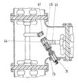
【図1】絶縁/アーススイッチの第1の例の断面図で,絶縁スイッチがオン,アーススイッチがオフの状態を示している。
【図2】図1に示す構成で,絶縁スイッチがオフ,アーススイッチがオフの状態を示している。
【図3】図1及び2に示す構成で,可動接点が第3の位置にあり,絶縁スイッチがオフ,アーススイッチがオンの状態を示している。
【図4】絶縁/アーススイッチ第2の例の断面図で,絶縁スイッチがオン,アーススイッチがオフの状態を示している。
【図5】図4に示す構成で,絶縁スイッチがオフ,アーススイッチがオフの状態を示している。
【図6】図4及び5に示す構成で,可動接点が第3の位置にあり,絶縁スイッチがオフ,アーススイッチがオンの状態を示している。
【符号の説明】
11,12…内側導体,31,32…内側導体,39…固定接点,43…可動接点,44…接点ハウジング(固定接点),51…アース接点。[0001]
BACKGROUND OF THE INVENTION
The present invention relates to a gas-insulated high-pressure switch with a metal case according to the premise of claim 1.
[0002]
[Prior art]
Insulation switches that can also be grounded are widely known.
[0003]
Many have an insulating blade that can be pivoted and pivoted to an insulated position and a grounded position.
[0004]
In the insulation switch, a push-in movement of a movable contact is used for disconnection / connection, and an earth blade-like earth contact for grounding is provided.
[0005]
[Problems to be solved by the invention]
It is an object of the present invention to provide a switch having a simple structure with the insulation / earthing switch described at the beginning.
[0006]
[Means for Solving the Problems]
The object of the present invention is achieved by the structure described in the characterizing portion of claim 1.
[0007]
According to the present invention, the movable contact is an indentation contact structure, and its movement path is angled with respect to the first and second inner conductors, and can move linearly within the contact housing forming the second contact. In this case, the central axis of the two fixed contacts and the ground contact and the central axis of the moving contact in the moving direction are in a straight line.
[0008]
In the first example of the present invention, the push-in movable contact is driven by a gear train, and its pinion is accommodated in the contact housing and meshes with the rack rod portion on the push-in contact. It is like that.
[0009]
In the second example, the movable contact is moved by a screw shaft that is rotated by a driving device arranged outside the case.
[0010]
In this case, the movable contact is hollow, and has a drive member provided with an internal screw with which the screw shaft meshes. In this case, the movable contact is not twisted when the screw shaft is twisted.
[0011]
In the development of the present invention, an opening is opened in the metal case, the cylindrical portion is held in the opening, the drive shaft passes through the outer base, and is connected to the screw shaft via an insulation bolt. The cylindrical portion is fixed to the ground contact.
[0012]
The fixed contact and the ground contact preferably have a cylindrical wall into which the movable contact is inserted.
[0013]
The conductive connection between the movable contact, the fixed contact, the contact housing and the ground contact is formed by connecting coil spring means arranged in the contact and contact housing.
[0014]
Two coil spring contacts are conveniently arranged on each contact in each case.
[0015]
In a particularly advantageous refinement, the contact housing is arranged on the support and forms a T-shape with the latter, the T-shaped transverse web being angled with respect to the support. The coil spring contact assigned to the contact housing is arranged at the free end of the contact housing.
[0016]
Further improvements and advantages of the present invention will be described in detail below with reference to the accompanying drawings showing two examples of the present invention.
[0017]
DETAILED DESCRIPTION OF THE INVENTION
The same reference numerals are assigned to the same members in the two insulation / ground switches.
[0018]
A
[0019]
As will be described in detail below, this partition insulator is in contact with an insulation /
[0020]
A
[0021]
A
[0022]
The
[0023]
The T-shaped web 27 is perpendicular to the
[0024]
The
[0025]
A
[0026]
In the position shown in FIG. 1, the
[0027]
On the inner surface of the
[0028]
The toothed rack rod or
[0029]
The
[0030]
The interior 55 of the
[0031]
[0032]
FIG. 1 shows the isolation / ground switch in a connected state. In this case, the
[0033]
By twisting the
[0034]
FIG. 2 shows an insulation / earthing switch in which the insulation switch is off and the earth switch is off .
[0035]
When the
[0036]
An insulator 60 corresponding to the
[0037]
Next, a description will be given with reference to FIG.
[0038]
Most of the members are the same as those in FIG. 1 and the same reference numerals are used.
[0039]
The insulation / ground switch is formed by a
[0040]
A threaded
[0041]
Within the T-web 27, the
[0042]
The
[0043]
Thus, the
[0044]
FIG. 4 shows a position where the insulation switch is on, and the
[0045]
In the position where the earth switch is on, the
[0046]
The
[0047]
FIG. 4 shows the position where the insulation switch is on.
[0048]
By twisting the
[0049]
When the
[0050]
Finally, to repeat, the central axis of the
[0051]
The connecting coil screw has a known configuration and is arranged in a groove in the corresponding contact. In the arrangements shown in FIGS. 1 to 4, these are each a pair of connecting coil springs.
[0052]
In the example shown in FIG. 1, the
[0053]
1 and 4, the movable contact is configured to move on the longitudinal axis so that the insulation switch is in the on position or the earth switch is in the on position.
[0054]
This is to make it impossible to operate the switch erroneously when the insulation switch is turned on or the earth switch is turned on.
[0055]
The connection coil springs provided at both ends of the
[Brief description of the drawings]
FIG. 1 is a cross-sectional view of a first example of an insulation / earth switch, showing a state in which the insulation switch is on and the earth switch is off.
FIG. 2 shows a state in which the insulation switch is off and the earth switch is off in the configuration shown in FIG.
FIG. 3 shows the state shown in FIGS. 1 and 2 in which the movable contact is in the third position, the insulation switch is off, and the earth switch is on.
FIG. 4 is a cross-sectional view of a second example of the insulation / earth switch, showing a state in which the insulation switch is on and the earth switch is off.
5 shows the state shown in FIG. 4 in which the insulation switch is off and the earth switch is off.
6 shows the state shown in FIGS. 4 and 5 in which the movable contact is in the third position, the insulation switch is off, and the earth switch is on. FIG.
[Explanation of symbols]
DESCRIPTION OF
Claims (10)
第1内側導体と直交する第2内側導体に接続される第2固定接点と,
固定アース接点と,
第1の位置で第2固定接点を第1固定接点に接続し,第2の位置で第2固定接点を固定アース接点に接続する可動接点と,
を備えた金属ケース入りガス絶縁高圧スイッチのための絶縁アーススイッチにおいて,
第1固定接点(39),第2固定接点(44),固定アース接点(51)及び可動接点(43)は,共通の一つのハウジング(17)の中に収容され,
第2固定接点(44)は,可動接点(43)を収容する接点ハウジングにより構成され,
前記可動接点(43,61)は,押込み接触構造であって,前記第1内側導体及び第2内側導体に対して角度(α)をなして動くように,前記接点ハウジング(44)でリニアにガイドされており,
前記第1固定接点及び第2固定接点の中心軸及びアース接点の中心軸並びに可動接点(43,61)の動き方向の中心軸は,一直線上にあることを特徴とする絶縁アーススイッチ。A first fixed contact connected to the first inner conductor ;
A second fixed contact connected to a second inner conductor orthogonal to the first inner conductor ;
A fixed earth contact ;
And the movable contact for connecting the second fixed contact in the first position connected to the first fixed contact, a second fixed contact on the fixed earth contact in the second position,
The insulating ground switch for metal cased gas insulated high-voltage switch with,
The first fixed contact (39), the second fixed contact (44), the fixed ground contact (51) and the movable contact (43) are accommodated in one common housing (17),
The second fixed contact (44) is constituted by a contact housing that houses the movable contact (43).
Said movable contact (43,61) is a push-contact structure, to move at an angle (alpha) relative to the first inner conductor and a second inner conductor, linear on the contact housing (44) Being guided,
The insulated earth switch, wherein the center axis of the first fixed contact and the second fixed contact, the center axis of the earth contact, and the center axis of the movable contact (43, 61) are in a straight line.
このT形の横方向の線を構成するクロスバーは,前記支持部(45)に対して角度(α)をなしていることを特徴とする請求項1から8の何れか1項に記載の絶縁アーススイッチ。The contact housing (44) is disposed on the support (45) and has a T shape with the latter .
Cross bars configuring the horizontal line of the T shaped, according to any one of claims 1 to 8, characterized in that an angle (alpha) relative to the support (45) Insulated earth switch.
Applications Claiming Priority (2)
| Application Number | Priority Date | Filing Date | Title |
|---|---|---|---|
| DE19632574.9 | 1996-08-13 | ||
| DE19632574A DE19632574A1 (en) | 1996-08-13 | 1996-08-13 | Disconnect earth switch for a metal-enclosed, gas-insulated high-voltage switchgear |
Publications (2)
| Publication Number | Publication Date |
|---|---|
| JPH10188746A JPH10188746A (en) | 1998-07-21 |
| JP3844565B2 true JP3844565B2 (en) | 2006-11-15 |
Family
ID=7802495
Family Applications (1)
| Application Number | Title | Priority Date | Filing Date |
|---|---|---|---|
| JP21750497A Expired - Lifetime JP3844565B2 (en) | 1996-08-13 | 1997-08-12 | Insulation / Earth switch |
Country Status (7)
| Country | Link |
|---|---|
| US (1) | US5828025A (en) |
| EP (1) | EP0824264B1 (en) |
| JP (1) | JP3844565B2 (en) |
| KR (1) | KR19980018452A (en) |
| CN (1) | CN1155034C (en) |
| AT (1) | ATE225565T1 (en) |
| DE (2) | DE19632574A1 (en) |
Families Citing this family (44)
| Publication number | Priority date | Publication date | Assignee | Title |
|---|---|---|---|---|
| DE19816366C1 (en) * | 1998-04-03 | 1999-11-11 | Siemens Ag | Encapsulation module with a three-phase switching device for a gas-insulated high-voltage switchgear |
| DE19816360C1 (en) * | 1998-04-03 | 1999-10-07 | Siemens Ag | Encapsulation module for gas-insulated HV switchgear |
| JP3559241B2 (en) * | 1998-04-03 | 2004-08-25 | シーメンス アクチエンゲゼルシヤフト | Hermetically sealed container module for gas-insulated switchgear with three-position switchgear incorporated in electrical circuit |
| DE19825386C2 (en) * | 1998-05-28 | 2000-05-11 | Siemens Ag | Encapsulation module with a combined isolating-earthing switch for a gas-insulated switchgear |
| DE29823222U1 (en) * | 1998-12-23 | 1999-02-25 | Siemens Ag | Gas-insulated, three-phase encapsulated switchgear |
| FR2805406B1 (en) † | 2000-02-23 | 2002-08-23 | Alstom | THREE-POSITION ELECTRIC SWITCH WITH AN AXIALLY MOBILE SWITCHING ELEMENT |
| DE10013232A1 (en) * | 2000-03-13 | 2001-09-20 | Siemens Ag | Outdoor multiphase encapsulated gas-insulated high-voltage (HV) switching equipment |
| KR100351301B1 (en) * | 2000-10-27 | 2002-09-05 | 엘지산전 주식회사 | Ground connection apparatus for circuit breaker |
| DE10219055B4 (en) * | 2002-04-24 | 2004-04-01 | Siemens Ag | High voltage arrangement with a housing and conductors |
| WO2005018066A2 (en) * | 2003-08-07 | 2005-02-24 | Areva T & D Sa | Three-position ground switch |
| DE10354595B4 (en) * | 2003-11-21 | 2005-09-22 | Abb Technology Ag | Spindle drive for a disconnector and / or earthing switch |
| DE102004001795A1 (en) | 2004-01-06 | 2005-08-11 | Siemens Ag | switching mechanism |
| DE102004006061A1 (en) * | 2004-01-30 | 2005-08-18 | Siemens Ag | High-voltage outdoor bushing arrangement |
| DE502004001795D1 (en) * | 2004-02-27 | 2006-11-30 | Abb Technology Ag | Compact earth switching device for gas-insulated switchgear |
| DE102006033209B3 (en) * | 2006-07-13 | 2007-11-08 | Siemens Ag | Circuit breaker e.g. three-position circuit breaker, for use in gas-insulated switchgear, has three contact units, of which one contact unit is arranged between inner surface of one of three connections and outer surface of casing |
| DE102006053376A1 (en) * | 2006-11-10 | 2008-05-15 | Abb Technology Ag | Electric high voltage train |
| JP5166061B2 (en) * | 2008-02-15 | 2013-03-21 | 株式会社東芝 | Gas insulated switchgear and method of assembling the same |
| DE102009022105A1 (en) * | 2009-05-20 | 2010-11-25 | Abb Technology Ag | Gas-insulated high-voltage switchgear |
| DE102009030610A1 (en) | 2009-06-23 | 2010-12-30 | Siemens Aktiengesellschaft | High-voltage arrangement |
| DE102009030608A1 (en) * | 2009-06-23 | 2010-12-30 | Siemens Aktiengesellschaft | High-voltage arrangement |
| DE102009036590B3 (en) * | 2009-08-07 | 2011-03-31 | Abb Technology Ag | Gas-insulated high-voltage switchgear |
| JP4906892B2 (en) | 2009-08-12 | 2012-03-28 | 株式会社日立製作所 | Switchgear |
| DE102010004981B3 (en) | 2010-01-18 | 2011-07-21 | Abb Technology Ag | Metal-enclosed, gas-insulated combined disconnector and earthing switch |
| CN102918617B (en) * | 2010-06-03 | 2015-05-13 | 三菱电机株式会社 | Opening and closing device |
| CN102074906B (en) * | 2010-12-13 | 2012-11-28 | 上海安越电气工程技术有限公司 | Transformer neutral point combination electric equipment |
| KR101286291B1 (en) * | 2011-05-16 | 2013-07-15 | 현대중공업 주식회사 | Gas-insulated switchgear |
| KR20120127851A (en) * | 2011-05-16 | 2012-11-26 | 현대중공업 주식회사 | Gas-insulated switchgear |
| DE102011111183B4 (en) * | 2011-08-25 | 2022-01-27 | Abb Power Grids Switzerland Ag | Driving device for a multi-position switch |
| CN102306559B (en) * | 2011-09-02 | 2013-10-09 | 平高集团有限公司 | Movable and static contact connection assembly and high-voltage isolation grounding switch |
| KR101238912B1 (en) * | 2011-09-08 | 2013-03-06 | 현대중공업 주식회사 | Sector gear and gas-insulated switchgear having the same |
| FR2981785B1 (en) * | 2011-10-25 | 2013-12-27 | Alstom Technology Ltd | DEVICE FOR ELECTRICALLY HANDLING A JUNCTION POINT BETWEEN TWO PARTS OF A NETWORK |
| CN103377849B (en) * | 2012-04-28 | 2016-08-17 | 西门子公司 | Three-phase combined type isolation earthing switch |
| CN102956396B (en) * | 2012-06-27 | 2015-08-26 | 厦门华电开关有限公司 | Compact ground isolation three-station |
| CN102969191A (en) * | 2012-11-08 | 2013-03-13 | 无锡恒驰中兴开关有限公司 | Linear motion type isolation grounding switch |
| CN102938345A (en) * | 2012-11-09 | 2013-02-20 | 川开电气股份有限公司 | Three-position isolating-grounding switch |
| JP5980103B2 (en) * | 2012-11-21 | 2016-08-31 | 三菱電機株式会社 | Gas insulated switchgear |
| CN103683083B (en) * | 2013-12-23 | 2016-03-30 | 昆明理工大学 | A kind of isolation earthing switch |
| DE102015215028A1 (en) | 2015-08-06 | 2017-02-09 | Siemens Aktiengesellschaft | Method for reporting a switching state of an electrical switching device and device for carrying out the method |
| CN105304360B (en) * | 2015-10-27 | 2018-04-03 | 平高集团有限公司 | A kind of three stations power cutoff mechanism and electric operating mechanism in place |
| CN105513845B (en) * | 2015-11-25 | 2018-08-24 | 河南平高电气股份有限公司 | A kind of earthing switch and its moving contact, moving conductive rod |
| CN105938996A (en) * | 2016-06-29 | 2016-09-14 | 上海纳杰电气成套有限公司 | Miniature high-voltage air-insulated switch cabinet busbar chamber structure |
| PT3439009T (en) * | 2017-08-03 | 2020-01-09 | Nuventura Gmbh | Circuit breaker for gas insulated switchgear |
| DE102020206884A1 (en) | 2020-06-03 | 2021-12-09 | Siemens Aktiengesellschaft | Load switch with blow piston switch and earthing function |
| CN112466701B (en) * | 2020-11-13 | 2024-03-26 | 许继(厦门)智能电力设备股份有限公司 | Double-break linkage type three-station isolation grounding switch structure |
Family Cites Families (12)
| Publication number | Priority date | Publication date | Assignee | Title |
|---|---|---|---|---|
| DE742003C (en) * | 1939-03-30 | 1943-11-20 | Licht Und Kraft Ag | Free-standing extinguishing chamber switch |
| DE1615835A1 (en) * | 1967-04-06 | 1971-09-09 | Bbc Brown Boveri & Cie | Separator for fully insulated electrical high-voltage switchgear |
| NL133619C (en) * | 1969-08-04 | |||
| NL135417C (en) * | 1970-02-27 | |||
| NL159830B (en) * | 1974-03-18 | 1979-03-15 | Coq Bv | CLOSED ELECTRICAL SWITCHING DEVICE FOR HIGH VOLTAGES WITH SERIES-CONNECTED SWITCHING FIELDS IN A CLOSED CHAIN. |
| JPS6025849B2 (en) * | 1976-04-27 | 1985-06-20 | 株式会社東芝 | Sealed switchgear |
| DE3224743A1 (en) * | 1982-07-02 | 1984-01-05 | Brown, Boveri & Cie Ag, 6800 Mannheim | Linear-travel disconnector for medium-voltage and high-voltage switching and distribution installations |
| DE8220782U1 (en) * | 1982-07-21 | 1984-06-14 | Licentia Patent-Verwaltungs-Gmbh, 6000 Frankfurt | Combined isolating and earthing module for metal-enclosed SF ↓ 6 ↓ gas-insulated switchgear |
| DE3913080A1 (en) * | 1989-04-21 | 1990-10-25 | Asea Brown Boveri | SPINDLE DRIVE |
| DE59406777D1 (en) * | 1994-04-19 | 1998-10-01 | Asea Brown Boveri | Disconnector for a metal-enclosed gas-insulated high-voltage switchgear |
| DE4420524A1 (en) * | 1994-06-13 | 1995-12-14 | Abb Management Ag | Metal-encapsulated gas-insulated switchgear |
| DE19519301A1 (en) * | 1995-05-26 | 1996-11-28 | Abb Management Ag | Disconnector for a metal-enclosed gas-insulated high-voltage switchgear |
-
1996
- 1996-08-13 DE DE19632574A patent/DE19632574A1/en not_active Withdrawn
-
1997
- 1997-08-07 AT AT97113620T patent/ATE225565T1/en active
- 1997-08-07 KR KR1019970037688A patent/KR19980018452A/en not_active Application Discontinuation
- 1997-08-07 DE DE59708362T patent/DE59708362D1/en not_active Expired - Lifetime
- 1997-08-07 EP EP97113620A patent/EP0824264B1/en not_active Expired - Lifetime
- 1997-08-12 JP JP21750497A patent/JP3844565B2/en not_active Expired - Lifetime
- 1997-08-12 CN CNB971156336A patent/CN1155034C/en not_active Expired - Lifetime
- 1997-08-13 US US08/910,650 patent/US5828025A/en not_active Expired - Lifetime
Also Published As
| Publication number | Publication date |
|---|---|
| CN1155034C (en) | 2004-06-23 |
| JPH10188746A (en) | 1998-07-21 |
| EP0824264A3 (en) | 1999-03-24 |
| KR19980018452A (en) | 1998-06-05 |
| EP0824264A2 (en) | 1998-02-18 |
| CN1173727A (en) | 1998-02-18 |
| DE59708362D1 (en) | 2002-11-07 |
| EP0824264B1 (en) | 2002-10-02 |
| DE19632574A1 (en) | 1998-02-19 |
| ATE225565T1 (en) | 2002-10-15 |
| US5828025A (en) | 1998-10-27 |
Similar Documents
| Publication | Publication Date | Title |
|---|---|---|
| JP3844565B2 (en) | Insulation / Earth switch | |
| KR101123223B1 (en) | Insulated earthing switch for gas-insulated switchgear assemblies | |
| US6559403B2 (en) | Three-position electrical switch having a switching element that is movable in axial translation | |
| JP4709756B2 (en) | Ground switch with 3 switch positions | |
| KR940004370B1 (en) | Compact-type gas-insulated switchgear apparatus | |
| KR100301378B1 (en) | High voltage switch panel | |
| EP0152611B1 (en) | Metal-enclosed gas-insulated switch installation | |
| EP0145994A2 (en) | Medium voltage switching device | |
| SU1477255A3 (en) | Disconnector for multipole cell of high-voltage switchgear | |
| CN1127110C (en) | Through-wall isolated vacuum load switch | |
| KR0130538B1 (en) | Metal-clad gas-insulated switch insulation with a cable | |
| KR100232696B1 (en) | Gas insulated switch gear | |
| KR900002892B1 (en) | Gas insulated switch gear | |
| CA2054359A1 (en) | Single-pole gas insulated line duct | |
| US4256934A (en) | Disconnecting switch arrangement | |
| JP7221473B1 (en) | gas insulated switchgear | |
| US4232925A (en) | High-voltage three phase electrical switch gear | |
| JPH0516808Y2 (en) | ||
| JP3906608B2 (en) | Switchgear | |
| US1010425A (en) | Electric switch. | |
| CN1273686A (en) | Vacuum switch and vacuum switch gear using the vacuum switch | |
| JPH04203A (en) | Gas insulated switchgear | |
| JPS60182620A (en) | Metal capsule gas insulated switching device | |
| TW200405376A (en) | A high-voltage metal-clad substation including a circuit-breaker with an insertion resistor mounted in a busbar | |
| JPH02284321A (en) | Gas insulated disconnector |
Legal Events
| Date | Code | Title | Description |
|---|---|---|---|
| A621 | Written request for application examination |
Free format text: JAPANESE INTERMEDIATE CODE: A621 Effective date: 20040625 |
|
| A977 | Report on retrieval |
Free format text: JAPANESE INTERMEDIATE CODE: A971007 Effective date: 20051007 |
|
| A131 | Notification of reasons for refusal |
Free format text: JAPANESE INTERMEDIATE CODE: A131 Effective date: 20051108 |
|
| A521 | Request for written amendment filed |
Free format text: JAPANESE INTERMEDIATE CODE: A523 Effective date: 20060125 |
|
| TRDD | Decision of grant or rejection written | ||
| A01 | Written decision to grant a patent or to grant a registration (utility model) |
Free format text: JAPANESE INTERMEDIATE CODE: A01 Effective date: 20060718 |
|
| A61 | First payment of annual fees (during grant procedure) |
Free format text: JAPANESE INTERMEDIATE CODE: A61 Effective date: 20060816 |
|
| R150 | Certificate of patent or registration of utility model |
Free format text: JAPANESE INTERMEDIATE CODE: R150 |
|
| FPAY | Renewal fee payment (event date is renewal date of database) |
Free format text: PAYMENT UNTIL: 20100825 Year of fee payment: 4 |
|
| FPAY | Renewal fee payment (event date is renewal date of database) |
Free format text: PAYMENT UNTIL: 20110825 Year of fee payment: 5 |
|
| FPAY | Renewal fee payment (event date is renewal date of database) |
Free format text: PAYMENT UNTIL: 20120825 Year of fee payment: 6 |
|
| FPAY | Renewal fee payment (event date is renewal date of database) |
Free format text: PAYMENT UNTIL: 20130825 Year of fee payment: 7 |
|
| R250 | Receipt of annual fees |
Free format text: JAPANESE INTERMEDIATE CODE: R250 |
|
| S111 | Request for change of ownership or part of ownership |
Free format text: JAPANESE INTERMEDIATE CODE: R313113 |
|
| R350 | Written notification of registration of transfer |
Free format text: JAPANESE INTERMEDIATE CODE: R350 |
|
| R250 | Receipt of annual fees |
Free format text: JAPANESE INTERMEDIATE CODE: R250 |
|
| R250 | Receipt of annual fees |
Free format text: JAPANESE INTERMEDIATE CODE: R250 |
|
| R250 | Receipt of annual fees |
Free format text: JAPANESE INTERMEDIATE CODE: R250 |
|
| EXPY | Cancellation because of completion of term |