JP3844500B2 - Applicators for holding and dispensing things - Google Patents
Applicators for holding and dispensing things Download PDFInfo
- Publication number
- JP3844500B2 JP3844500B2 JP52094596A JP52094596A JP3844500B2 JP 3844500 B2 JP3844500 B2 JP 3844500B2 JP 52094596 A JP52094596 A JP 52094596A JP 52094596 A JP52094596 A JP 52094596A JP 3844500 B2 JP3844500 B2 JP 3844500B2
- Authority
- JP
- Japan
- Prior art keywords
- applicator
- finger grip
- grip ring
- outer layer
- inner layer
- Prior art date
- Legal status (The legal status is an assumption and is not a legal conclusion. Google has not performed a legal analysis and makes no representation as to the accuracy of the status listed.)
- Expired - Fee Related
Links
Images


Classifications
-
- A—HUMAN NECESSITIES
- A61—MEDICAL OR VETERINARY SCIENCE; HYGIENE
- A61F—FILTERS IMPLANTABLE INTO BLOOD VESSELS; PROSTHESES; DEVICES PROVIDING PATENCY TO, OR PREVENTING COLLAPSING OF, TUBULAR STRUCTURES OF THE BODY, e.g. STENTS; ORTHOPAEDIC, NURSING OR CONTRACEPTIVE DEVICES; FOMENTATION; TREATMENT OR PROTECTION OF EYES OR EARS; BANDAGES, DRESSINGS OR ABSORBENT PADS; FIRST-AID KITS
- A61F13/00—Bandages or dressings; Absorbent pads
- A61F13/15—Absorbent pads, e.g. sanitary towels, swabs or tampons for external or internal application to the body; Supporting or fastening means therefor; Tampon applicators
- A61F13/20—Tampons, e.g. catamenial tampons; Accessories therefor
- A61F13/26—Means for inserting tampons, i.e. applicators
-
- B—PERFORMING OPERATIONS; TRANSPORTING
- B31—MAKING ARTICLES OF PAPER, CARDBOARD OR MATERIAL WORKED IN A MANNER ANALOGOUS TO PAPER; WORKING PAPER, CARDBOARD OR MATERIAL WORKED IN A MANNER ANALOGOUS TO PAPER
- B31B—MAKING CONTAINERS OF PAPER, CARDBOARD OR MATERIAL WORKED IN A MANNER ANALOGOUS TO PAPER
- B31B50/00—Making rigid or semi-rigid containers, e.g. boxes or cartons
- B31B50/74—Auxiliary operations
- B31B50/81—Forming or attaching accessories, e.g. opening devices, closures or tear strings
- B31B50/84—Forming or attaching means for filling or dispensing contents, e.g. valves or spouts
-
- B—PERFORMING OPERATIONS; TRANSPORTING
- B31—MAKING ARTICLES OF PAPER, CARDBOARD OR MATERIAL WORKED IN A MANNER ANALOGOUS TO PAPER; WORKING PAPER, CARDBOARD OR MATERIAL WORKED IN A MANNER ANALOGOUS TO PAPER
- B31F—MECHANICAL WORKING OR DEFORMATION OF PAPER, CARDBOARD OR MATERIAL WORKED IN A MANNER ANALOGOUS TO PAPER
- B31F1/00—Mechanical deformation without removing material, e.g. in combination with laminating
- B31F1/0003—Shaping by bending, folding, twisting, straightening, flattening or rim-rolling; Shaping by bending, folding or rim-rolling combined with joining; Apparatus therefor
- B31F1/0038—Rim-rolling
-
- B—PERFORMING OPERATIONS; TRANSPORTING
- B31—MAKING ARTICLES OF PAPER, CARDBOARD OR MATERIAL WORKED IN A MANNER ANALOGOUS TO PAPER; WORKING PAPER, CARDBOARD OR MATERIAL WORKED IN A MANNER ANALOGOUS TO PAPER
- B31F—MECHANICAL WORKING OR DEFORMATION OF PAPER, CARDBOARD OR MATERIAL WORKED IN A MANNER ANALOGOUS TO PAPER
- B31F1/00—Mechanical deformation without removing material, e.g. in combination with laminating
- B31F1/008—Shaping of tube ends, e.g. flanging, belling, closing, rim-rolling or corrugating; Fixing elements to tube ends
- B31F1/0087—Rim-rolling
-
- B—PERFORMING OPERATIONS; TRANSPORTING
- B31—MAKING ARTICLES OF PAPER, CARDBOARD OR MATERIAL WORKED IN A MANNER ANALOGOUS TO PAPER; WORKING PAPER, CARDBOARD OR MATERIAL WORKED IN A MANNER ANALOGOUS TO PAPER
- B31B—MAKING CONTAINERS OF PAPER, CARDBOARD OR MATERIAL WORKED IN A MANNER ANALOGOUS TO PAPER
- B31B2105/00—Rigid or semi-rigid containers made by assembling separate sheets, blanks or webs
- B31B2105/002—Making boxes characterised by the shape of the blanks from which they are formed
- B31B2105/0022—Making boxes from tubular webs or blanks, e.g. with separate bottoms, including tube or bottom forming operations
-
- B—PERFORMING OPERATIONS; TRANSPORTING
- B31—MAKING ARTICLES OF PAPER, CARDBOARD OR MATERIAL WORKED IN A MANNER ANALOGOUS TO PAPER; WORKING PAPER, CARDBOARD OR MATERIAL WORKED IN A MANNER ANALOGOUS TO PAPER
- B31B—MAKING CONTAINERS OF PAPER, CARDBOARD OR MATERIAL WORKED IN A MANNER ANALOGOUS TO PAPER
- B31B2120/00—Construction of rigid or semi-rigid containers
- B31B2120/002—Construction of rigid or semi-rigid containers having contracted or rolled necks, having shoulders
-
- B—PERFORMING OPERATIONS; TRANSPORTING
- B31—MAKING ARTICLES OF PAPER, CARDBOARD OR MATERIAL WORKED IN A MANNER ANALOGOUS TO PAPER; WORKING PAPER, CARDBOARD OR MATERIAL WORKED IN A MANNER ANALOGOUS TO PAPER
- B31B—MAKING CONTAINERS OF PAPER, CARDBOARD OR MATERIAL WORKED IN A MANNER ANALOGOUS TO PAPER
- B31B50/00—Making rigid or semi-rigid containers, e.g. boxes or cartons
- B31B50/25—Surface scoring
-
- B—PERFORMING OPERATIONS; TRANSPORTING
- B31—MAKING ARTICLES OF PAPER, CARDBOARD OR MATERIAL WORKED IN A MANNER ANALOGOUS TO PAPER; WORKING PAPER, CARDBOARD OR MATERIAL WORKED IN A MANNER ANALOGOUS TO PAPER
- B31B—MAKING CONTAINERS OF PAPER, CARDBOARD OR MATERIAL WORKED IN A MANNER ANALOGOUS TO PAPER
- B31B50/00—Making rigid or semi-rigid containers, e.g. boxes or cartons
- B31B50/26—Folding sheets, blanks or webs
- B31B50/28—Folding sheets, blanks or webs around mandrels, e.g. for forming bottoms
-
- B—PERFORMING OPERATIONS; TRANSPORTING
- B31—MAKING ARTICLES OF PAPER, CARDBOARD OR MATERIAL WORKED IN A MANNER ANALOGOUS TO PAPER; WORKING PAPER, CARDBOARD OR MATERIAL WORKED IN A MANNER ANALOGOUS TO PAPER
- B31B—MAKING CONTAINERS OF PAPER, CARDBOARD OR MATERIAL WORKED IN A MANNER ANALOGOUS TO PAPER
- B31B50/00—Making rigid or semi-rigid containers, e.g. boxes or cartons
- B31B50/74—Auxiliary operations
- B31B50/81—Forming or attaching accessories, e.g. opening devices, closures or tear strings
Description
背景技術
本発明は、物を保持、分与するのに適したアプリケーター、及び該アプリケーターの端部にカールを形成するための装置に関するものである。本発明は特に、タンポン・アプリケーター上に外側に延びた一体型のフィンガーグリップ・リングを形成するための装置に関するものである。
今日では、人間又は動物の体腔内或いは皮膚上に製品或いは物を分与するのに利用することの出来る沢山の種類のアプリケーターが知られている。タンポン・アプリケーターは特に、月経液、血液、その他の体液を吸収するため女性の膣内に月経用タンポンを挿入するために使われる。
タンポン・アプリケーターとしては様々な形状とサイズのものが利用されている。あるアプリケーターは紙、厚紙、ボール紙等で作られ、又あるものは樹脂で出来ていたり、2つ或いはそれ以上の異なる材料の積層物であったりする。アプリケーターは、ユーザーが自分の指を使ってタンポンを放出するような単一部材であってもよいし、はめ込み式に組み合わされた2つ或いはそれ以上の部材から形成されていてもよい。代表的な2部品構成のアプリケーターではタンポンを収納するための中空チューブと、その第1のチューブと相互に作用してタンポンを女性の膣内に放出する第2のチューブ若しくはプランジャーとを用いている。
単体型アプリケーターを使用する際、ユーザーは通常自分の親指と中指でアプリケーター・チューブを自分の膣近くに保持、位置決めする。それから人指し指を使ってタンポンを自分の膣内に放出する。2体型アプリケーターの場合、ユーザーは通常自分の親指と中指でアプリケーターの外側チューブを自分の膣近くに保持、位置決めする。それから内側チューブを外側チューブ内に人指し指を使って押し込み、タンポンを自分の膣内に放出する。タンポンを放出した後、アプリケーターを引き出して捨てる。女性にとっては、内側及び/又は外側チューブにフィンガー・リングが付いていれば、自分の膣に外側チューブを位置決め制御しやすいということが解った。
一体成形されたフィンガーグリップ・リングは、剪断強さを強くし易く、又製品の製造も簡単化できるので、非一体型フィンガーグリップよりも高く評価されている。フィンガーグリップ・リングは、タンポン或いは他の物を体腔内に快適に挿入するため、アプリケーターを制御しやすいようなサイズ、形状にしておかなければならない。従来、タンポン・アプリケーター、特に紙製アプリケーターで、直径1.25インチ(約31.75mm)以下のタンポン・アプリケーターに一体成形されたフィンガーグリップ・リングを量産することは大変難しかった。その理由の一つは、小径チューブ状部材に成形された紙はカーリング操作が行われる際、非常に裂けたり破れたりし易いということである。従って、米国特許1,181,965及び3,065,677で教示されている装置は、紙とカーリング・ツール間に発生する摩擦力が文字通り製品を壊すであろう事より満足には作動しない。
たとえチューブ状部材が紙製で非常に小径の場合であっても、チューブ状部材の端部にカールを形成するため、本装置が発明された。
発明の概要
簡単に言えば本発明はアプリケーター、特に、分与できる製品或いは物を受容し保持するのに適したタンポン・アプリケーターに関するものである。本発明は又、アプリケーター端部にカールを成形するための装置にも関する。アプリケーターは第1及び第2部材を含んでいる。第1部材はチューブ状部材を保持でき、そのチューブ状部材の第1端部が外側肩部を越して伸びているそのような外側肩部を有している。第2部材は第1部材と同軸に配置され、チューブ状部材の第1端部と係合できる。第2部材は、チューブ状部材の第1端部内に挿入できるサイズのパイロットを含んでいる。第2部材は又、パイロットを取り巻き、第2部材がカーリング・チャンバーを形成するためチューブ状部材の第1端部と係合するときに外側肩部と共に働くスリーブを含んでいる。第2部材は又更に、パイロットとスリーブとの間に位置しチューブ状部材の第1端部と接触できるカーリング・エレメントを含んでいる。装置は又更に、部材の一つを回転する手段と第2部材を動かしてチューブ状部材と係合させる手段とを含んでいる。カーリング・エレメントがチューブ状部材の第1端部と接触すると、カーリング・チャンバーの境界内でカールがその上に形成される。
アプリケーター端部上にカールを形成するための装置は第1及び第2部材を含んでいる。第1部材はチューブ状部材を保持でき、そのチューブ状部材の第1端部が外側肩部を越して伸びているそのような外側肩部を有している。第2部材は第1部材と同軸に配置され、チューブ状部材の第1端部と係合できる。第2部材はチューブ状部材の第1端部内に挿入できるサイズのパイロットを含んでいる。第2部材は又、パイロットを取り巻き、第2部材がカーリング・チャンバーを形成するためチューブ状部材の第1端部と係合するときに外側肩部と共に働くスリーブを含んでいる。第2部材は更に、パイロットとスリーブとの間に位置し、チューブ状部材の第1端部と接触できるカーリング・エレメントを含んでいる。装置は更に、部材の一つを回転する手段と第2部材を動かしてチューブ状部材と係合させる手段とを含んでいる。カーリング・エレメントがチューブ状部材の第1端部と接触すると、カーリング・チャンバーの境界内でカールがその上に形成される。
本発明の一般的目的はアプリケーターの端部にカールを成形するための装置、及び材料を受容、保持、分与するのに適したアプリケーターを提供することである。本発明の更に特定の目的は、チューブ状部材上に内側又は外側に伸びるカールを形成するための装置を提供することにある。
本発明のもう一つの目的は、アプリケーターの端部にカールを形成する装置を提供することである。
更に、本発明の目的は、小径の、紙製チューブ端部にカールを形成する装置を提供することである。
更に、本発明の目的は、タンポン・アプリケーター上に、フィンガーグリップとして働き得る外側に伸びた一体のカールを形成できる装置を提供することである。
本発明の更なる目的は、タンポン・アプリケーター上に、フィンガーグリップリングとして働き得る外側に伸びた一体のカールを形成できる装置を提供することである。
本発明の更にもう一つの目的は、素早くかつ効率的にチューブ状部材の端部をカールすることの出来る装置を提供することである。
更に、本発明の目的は、経済的に効果のある方法でかつ比較的早い製造速度でチューブ状部材の端部をカールすることの出来る装置を提供することである。
本発明のこの他の目的及び利点は、以下の説明と添付図面により当業者にはより明確となろう。
【図面の簡単な説明】
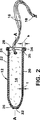
図1はアプリケーターの側面図である。
図2はタンポン綿撒糸を中に保持している、図1に示すアプリケーターの断面図である。
図3は「中空C型」カール形状のフィンガーグリップ・リングを一体的に成形した外側チューブの部分断面図である。
図4は「閉口C型」カール形状のフィンガーグリップ・リングを一体的に成形した外側チューブの部分断面図である。
図5は「波C型」カール形状のフィンガーグリップ・リングを一体的に成形した外側チューブの部分断面図である。
図6は「e型」カール形状のフィンガーグリップ・リングを一体的に成形した外側チューブの部分断面図である。
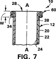
図7は「右S型」カール形状のフィンガーグリップ・リングを一体的に成形した外側チューブの部分断面図である。
図8は「左S型」カール形状のフィンガーグリップ・リングを一体的に成形した外側チューブの部分断面図である。
図9は内側チューブが外側チューブに対して伸縮滑動可能な2体型タンポンアプリケーターの外観図である。
図10はタンポン綿撒糸を外側チューブ内に保持している、図9に示す2体型タンポンアプリケーターの断面図である。
図11はチューブ状部材端部に外向きのカールを成形するための装置の側面図である。
図12は図11に示す装置の断面図である。
図13は図11の矢視13−13に沿った第1部材の端面図である。
図14は図11の矢視14−14に沿った第2部材の端面図である。
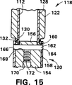
図15はチューブ状部材の一端部に外側に伸びるカールを成形するための第1及び第2部材の相互作用を示す拡大図である。
図16は、図15に示すカーリング・エレメントを使って、外側に伸びる一体型のカールがその端部に成形されたチューブ状部材の拡大図である。
図17はチューブ状部材の一端部に外側に伸びるカールを成形するための第1及び第2部材の相互作用を示す拡大図である。
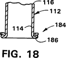
図18は、図17に示すカーリング・エレメントを使って、外側に伸びる一体型のカールがその端部に成形されたチューブ状部材の拡大図である。
図19はチューブ状部材端部に内向きのカールを成形するための装置の断面図である。
図20は、図19に示すカーリング・エレメントを使って、内側に伸びる一体型のカールがその端部に成形されたチューブ状部材の拡大図である。
好ましい実施例の詳細な説明
図1及び図2において、アプリケーター10は中空部材12の形に描かれており、これは分与できる物14を保持するように設計されている。アプリケーター10の直径は比較的小さく、約1インチ(約25.4mm)以下である。アプリケーター10の全長は、約2ないし12インチ(約50.8mmないし304.8mm)の間にあるが、必要ならばもっと短くても長くてもよい。アプリケーター10がタンポン・アプリケーターとして用いられる際には、その長さは約1インチないし3インチ(約25.4mmないし76.2mm)の範囲とすべきである。
物14は殆ど何でもよく、液体、固体、顆粒状、ペースト状の薬品を収めたカプセル、医療用品、吸収材、月経タンポン、栄養物等々がこれに含まれる。本発明をタンポン・アプリケーター10を例に説明するが、アプリケーター10は物14を人や動物の皮膚上に分与するのにも利用できる。
物14がタンポンである場合、通常、そこから外側に伸びた撤収用の糸16が付いている。撤収用糸16は汚れたタンポンを女性の膣から取り出すのに用いられる。撤収用糸16には、この撤収用糸16がタンポン14から分離しないように結び目18を設けておいてもよい。
中空部材12は薄い壁20を持った長いチューブ状の形であり、円形断面であるのが望ましい。壁20の厚さ「t」(図2参照)は約0.10インチ(2.54mm)以下であり、約0.03インチ(0.762mm)以下であることが望ましく、約0.02インチ(0.5mm)以下であることが更に望ましい。中空部材12は少なくとも2つの別々の異なった層22及び24で形成されている。2つの層22と24だけが描かれているが、中空部材12は3つ或いはそれ以上の層を含んでいてもよい。層22及び24は、紙、厚紙、ボール紙、樹脂、熱可塑性フィルム、その他何であれ適切な材料で形成することが出来る。本発明の目的に照らし、紙層上のフィルム・コーティングも2層構造と解釈される。
層22と24は、にかわのような接着剤、熱、圧力、熱と圧力の組み合わせ、超音波、その他あらゆる既知の方法で互いに接着することができる。代わりに、層22と24を積層シートに成形して、後でチューブ状のアプリケーター10に成形してもよい。望むならば、層22と24双方を同一の材料から成形することも可能である。しかし経済上の理由から、内側の層は通常、より低価格の材料で形成される。先に述べたように層22と24は外径約1インチ(25.4mm)以下の中空チューブ状部材に成形される。このように比較的小さな径は、材料を互いに回旋巻き、螺旋巻き、長手方向のシーミング等をして作ることができる。
内側層24を形成するのに使われる材料は、カール状に成形できるよう伸長性がなければならない。重要なことは、最も内側の層24はフィンガーグリップ・リング34の外表面を形成することになるので、隣接する外側の層よりも伸長性がなければならないということである。即ち、最も内側の層24は外側の層22よりも大きな径に成形されるので、外側の層22よりも伸長性がない場合には、破れるか変形するかして、そのために貧弱な格好のフィンガーグリップ・リングを作ることとなる。内側の層24は外側の層22よりも少なくとも4%、望ましくは6%、更に望ましくは8%以上伸長できなければならない。伸長の量は、中空チューブ状部材12がどのように成形されるかにより、機械の方向又はそれと直角方向の何れかでよい。
外側の層22に平滑又は滑らかな外観及び/又は感覚を与えるために、その上に付加的な層をコーティング又はスプレー吹き付けすることも可能である。コーティングすれば、アプリケーター10と女性の膣のような体腔との間の摩擦が低減でき、アプリケーター10の体腔内への挿入、及びそこからの取り外しを快適に行う助けとなる。視覚的に異なった外観を与えるように、異なる層22と24に着色することもできる。例えば、外側層22を白に、内側層24をピンクに着色してもよい。そうすれば、2つの層22と24がカールされたとき、内側層24がフィンガーグリップ・リング34の外表面を形成するから、完成品はピンクのフィンガーグリップ・リングが付いた白のアプリケーター10ということになる。
アプリケーター10は又、第1と第2の各々離れた分離端部26と28を有している。第1端部26はアプリケーター10を体腔に快適に挿入しやすい形にすることができる。第1端部26は丸くしても、半球形にしても、テーパを付けても、弾丸形状にしてもよい。第1端部26は又、そこを通ってタンポン14が放出される際に半径方向に外側に曲がることのできる、複数の独立した花弁状部30を含んでいてもよい。代わりに、第1端部26は、物14が放出できるように拡張して大きな開口部を提供できる複数のプリーツ(図示せず)で構成してもよい。第1端部26は完全に閉じられていてもよいが、アプリケーター10の中心軸A−Aに沿って配列された中央開口部32を有しているのが望ましくい。開口部32は約1/16インチ(1.587mm)以上であればよく、中空部材12から物14を放出するとき、これに掛けなければならない力に制限を設ける目的に利用できる。必要な放出力が低いほど、物14を体腔内に快適に挿入するのが容易になる。又、中央開口分32があれば、ユーザーがアプリケーター10を視認検査し、使用する物14が確かにあることを確認できる。
アプリケーター10の第2端部28に隣接して、フィンガーグリップ・リング34が一体成形されている。フィンガーグリップ・リング34は中心軸A−Aに関し半径方向外側に伸びている。フィンガーグリップ・リング34の図1に示す幅wは中心長手軸A−Aに並行に測った寸法で定義され、約0.02インチないし0.10インチ(O.5mmないし2.54mm)或いはそれ以上でなければならない。幅wは約0.05インチないし0.08インチ(1.27mmないし2.03mm)であるのが望ましい。又、フィンガーグリップ・リング34の図2に示す高さhは少なくとも約0.1インチ(2.54mm)で、外側層22の外表面上に伸びた寸法である。フィンガーグリップ・リング34の高さは事実上アプリケーター10の外径を約5%ないし25%増やすこととなる。
フィンガーグリップ・リング34は、その3つの基本的な機能を果たすことができるように、十分な高さ(h)を有していることも又重要である。ユーザーの皮膚又は体腔に対してアプリケーター10の位置を適切に制御するためには、ユーザーが指先でフィンガーグリップ・リング34を感知できて、アプリケーター10の第2端部28がどこに位置しているかを知ることができるように、フィンガーグリップ・リング34は十分な高さ(h)を有していなければならない。フィンガーグリップ・リング34は又、ユーザーがアプリケーター10を親指と中指の間で回転させ、自分の膣に対してアプリケーター10の相対的な位置決めをし易くする。フィンガーグリップ・リング34の高さ(h)が高いほど、ユーザーはアプリケーター10を手先で回転させ易い。第2の機能はタンポン14を中空部材12から放出することである。フィンガーグリップ・リング34は、タンポン14を第1端部26から放出するときに、ユーザーの指先が中空部材12から滑って外れないように、十分な高さ(h)を有していなければならない。うまく機能するためには、フィンガーグリップ・リング34の外径は中空部材12の外径よりも少なくとも約5%大きくなければならない。フィンガーグリップ・リング34の外径は中空部材12の外径よりも約8%ないし20%大きいのが望ましい。更に言えば、フィンガーグリップ・リング34の外径は中空部材12の外径よりも約12%ないし16%大きいのが最も望ましい。
フィンガーグリップ・リング34の3番目の機能は、ユーザーの皮膚、膣、その他の体腔からアプリケーター10を取り外しやすくすることである。フィンガーグリップ・リング34は、ユーザーの指がアプリケーター10から滑って外れることなくこの機能を果たせるように、十分な高さ(h)を有していなければならない。
再び図2に関してだが、フィンガーグリップ・リング34は、基本的に中空部材12の壁20に垂直な面35を含んでいる。この面35は、ユーザーの指からこの面35に力が掛けられたときに、アプリケーター10の第1端部26がフィンガーグリップ・リング34の周りに回転できるように、十分な強度を有していなければならない。このような回転運動はアプリケーター10の体腔に対する相対的位置決めをやりやすくする。
アプリケーター10を形成する材料の強度と延び特性がフィンガーグリップ・リング34の最大外径に制限を掛ける。アプリケーター10の最大外径は、異なる種類の材料に対して、次の式で計算できる。

フィンガーグリップ・リング34は、ユーザーの指が使用中にフィンガーグリップ・リング34を壊したり、カールを解いたりしないように十分な強度を有していなければならない。フィンガーグリップ・リング34は、力が掛けられる3つの異なった期間に出会う。3つの期間とは、アプリケーターが体腔に対して位置決めされる制御期間、物が体腔内に放出される放出期間、及びアプリケーター10が体腔から取り除かれる除去期間である。フィンガーグリップ・リング34が耐えなければならない最初の力は、ユーザーがアプリケーター10を体腔付近及びその中へ位置決めするときの押し込み力である。通常、フィンガーグリップ・リング34には2本の指だけが置かれ、フィンガーグリップ・リング34に加えられる力は円周上に等分布されるわけではない。そうではなく、力は互いに約180度離れた2つの弧状の位置でフィンガーグリップ・リング34の周辺に作用する。各弧状の位置は約45度と約110度との間で定義される面積を包含することとなる。この期間の力は約50grから約200grの範囲にある。
フィンガーグリップ・リング34に掛けられる第2の力は放出期間の力で、このときの力が最大の力となる。この力は、物が体腔内に放出される際に、中空部材12の長手中心軸A−Aに平行な方向に、フィンガーグリップ・リング34に掛けられる。この力はフィンガーグリップ・リング34がカールされた方向と逆方向となる。多くのタンポンアプリケーターの放出力は約250grから800gr(0.551bから1.751b)の範囲にある。それ故、フィンガーグリップ・リング34の強度は少なくとも約250gr(0.551b)必要であり、望ましくは800gr(1.751b)以上、更に安全のためには1500gr(3.301b)以上であることが望ましい。
フィンガーグリップ・リング34が耐えなければならない3番目の力は、アプリケーター10が体腔より引き出される際の除去力である。この力は制御時の力同様約50grから200grの範囲にある。
フィンガーグリップ・リング34の強度、或いは変形するかカールが解けるかする迄に掛け得る力は、ディジタル・フォース・ゲージが装備されたシャティロン・フォース・テスターを使って計測できる。両装置とも27409ノースカリフォルニア、グリーンスボロ、ビジネス・パーク・ドライブ、7609のシャティロンより入手できる。引張/圧縮テスター・モデルTCM−200とシャティロン・ディジタル・フォース計モデルDFIが役に立つ。
フィンガーグリップ・リング34は、ユーザーの親指やその他の指の先が当たるストッパーとなり、かつユーザーの他の指又は他の部材で物14をアプリケーター10の前端の第1端部26を通して押し出せる構造となっている。
フィンガーグリップ・リング34を作るに必要なカールの量は、フィンガーグリップ・リング34の形状、アプリケーター10を形成するために使われた材料の種類、層の数、組み合わされた層の厚さ等々によって変わり得る。通常、アプリケーター10の第2端部28がそれ自身の上に少なくとも180度カールされる。他の言い方をすれば、層22と24は、少なくとも一つの折り返しがあり、カールを形成する材料がチューブ状部材12を形成する層22及び24と並行になるまでカールされる。幾つかの実施例では、材料を約180度と450度との間でカールする必要があるか或いはそうするのが望ましい。ある種のカール形状では、約270度から360度の間でカールする必要がある。
図3から図8までに幾つかの特定のカール形状を示す。図3に、アプリケーター10の第2端部28上に形成された「中空C型カール」36を示す。「中空C型カール」36は、チューブ状アプリケーター10の末端38が第1層即ち外側層22に接触するように、22と24の両層を約270度カールして作る。「中空C型カール」36はC型断面形状を有している。更に、「中空C型カール」36は中空中心即ち中空領域40を有している。
図4に、アプリケーター10の第2端部28上に形成されたもう一つの「C型カール」44を示す。「C型カール」44は、チューブ状アプリケーター10の末端38が第1層即ち外側層22に接触するように、22と24の両層を約270度カールして作る。更に、22と24の両層は成形過程の間に中空チューブ状部材12に向かって、それと感知できる空間領域ができないよう圧力が掛けられる。この形状は図3のものに比べ開放領域が少ないが、カール44には限られた中空領域がなお存在する。
図5に、アプリケーター10の第2端部28上に形成された「波型カール」46を示す。「波型カール」46は、チューブ状アプリケーター10の末端38が第1層即ち外側層22に接触するように、22と24の両層を約270度カールして作る。更に「波型カール」46は中空中心即ち中空領域48を有している。中空領域48のため「波型カール」46の密度はチューブ状壁20を形成する材料よりもやや低くなる。「波型カール」46が形成される間に、22と24の両層の材料は交互に隆起部50と溝部52を持った折り返し形状に成形される。隆起部50と溝部52は「波型カール」46の外側表面54、内側表面56の両面に発生する。外側表面54上の隆起部50と溝部52は粗い表面を形成し、ユーザーの手が滑りにくくなる。
図6に、アプリケーター10の第2端部28上に形成された「e型カール」58を示す。「e型カール」58の外観は、長手軸A−Aと並行方向を向いた逆e断面形状である。「e型カール」58は、チューブ状アプリケーター10の末端38が外側層22と並行になりかつそれに隣接するように、22と24の両層を約360度カールして作る。この実施例では中空領域は存在しない。しかし、カーリングの途中及び/又は後で圧縮が加えられるとすれば、その圧縮量によっては「e型カール」の折り返しの線に沿って中空領域が存在してもよい。第1層22と第2層24を各々伸長しカーリングすることによって、フィンガーグリップ・リング34の密度がチューブ状壁20を形成する材料よりも低くなるかも知れないことも理解されなければならない。
図7及び図8に、アプリケーター10の第2端部28上に形成されたS型カールの2つのバージョンを示す。図7に「右Sカール」60を、図8に「左Sカール」62を示す。「右Sカール」60は、Sの自由端を第1層即ち外側層22の外表面に隣接、そして接触するように配置してS型を作る。「左Sカール」62は、Sの自由端を第1層即ち外側層22の外表面から離し、約90度外向きに配置してS型を作る。右及び左の「Sカール」60及び62はS型の断面形状を有している。
幾つか、特定のカール形状について示し、説明したが、本特許から逸脱することなく他のカール形状を採りうることは言うまでもない。
再び図3〜8についてであるが、フィンガーグリップ・リング34内にある材料の量はカールの断面図を見ればよくわかる。断面図を見れば、各カールがチューブ壁材と、通常は幾分の中空領域40とから成っていることがわかる。チューブ壁が高価ではない材料で出来ていて、典型的多層構造材であれば、ある程度十分な厚さを持たせることができる。これによってアプリケーターには外から働く圧力に耐える十分な強度を与えることができる。外部に伸びるフィンガーグリップ・リング34も又、使用中適切に機能するための十分な強度と高さを持っていなければならない。フィンガーグリップ・リング34の外径は基本的にチューブの外径より大きく、このことはフィンガーグリップ・リング34のより大きな径を構成するために、紙の繊維が変わるか伸びるかしていることを意味している。それ故、材料のタイプ、材料の厚さ、材料の伸び、チューブの初期外径、フィンガーグリップ・リング34の外径の全てが相互に関係する。従って、この相互作用を説明するのに用いられる2つの用語は、フィンガーグリップ・リング34の「断面積」と「壁密度」である。
各フィンガーグリップ・リング34の「断面積」はチューブ材のパーセンテージと中空領域40の補完パーセンテージとから成っている。各フィンガーグリップ・リング34の「断面積」は約70ないし95%の材料物質と、約5ないし30%の補完中空領域とから成っている。各フィンガーグリップ・リング34の断面積は約80ないし90%の材料物質と、約10ないし20%の補完中空領域とから成っているのが望ましい。このフィンガーグリップ・リング34中の材料物質の割合は現在使われている紙製飲料コップよりもはるかに高く、この紙コップの場合カール部分の材料物質の割合は約10ないし20%、中空領域は約80ないし90%である。フィンガーグリップ・リング34中の材料物質の中空領域に対する割合は、リングを形成する材料のタイプ、必要とされる高さ寸法「h」、必要とされる強度等によって決められる。フィンガーグリップ・リング34の高さと強度とは、アプリケーター10の制御、挿入、除去にフィンガーグリップ・リング34がいかに効果的に役立つかを決める決定的なパラメーターであることが分かっている。
各フィンガーグリップ・リング34の「壁密度」は、1981年に版権が取られ、フリン/トロージャンから発行されている「工業用材料とその応用」第2版52頁に定義されている密度の標準定義を使って決められる。密度は「質量/体積」で定義され、通常はgr/cm3又はkg/m3で表される。適切なフィンガーグリップ・リング34を形成するには、チューブ状壁20の密度は約0.4ないし1.0gr/cm3でなければならない。2プライのアプリケーターでは約0.6gr/cm3の密度がよい。フィンガーグリップ・リング34を形成する壁の密度はチューブ状壁20の密度よりも低いのが望ましい。しかし、許容範囲はチューブ状壁20の密度の±20%である。
フィンガーグリップ・リング34は、中空部材12の周辺の一端を回転する工具に接触させて作ることができる。工具は中空部材12に接触し、その長手中心線A−Aに並行に動く。チューブ状壁20がフィンガーグリップ・リング34にカールされてゆくに従って、内側層24が紙のような材料で出来ている場合、内側層24の繊維は伸長され成形される。そのため、顕微鏡のスケールでは、繊維は離され又は空間が空くことになる。その結果、材料の密度は低下する。フィンガーグリップ・リング34が続いて圧縮されなければ、中空部材12より低密度で、中空領域を含むこととなる。フィンガーグリップ・リング34を圧縮して中空領域を減らすか又は取り除くことも出来る。そうすればフィンガーグリップ・リング34の密度は上がる。フィンガーグリップ・リング34は形成の元となったチューブ状壁20より高密度になるように圧縮することもできる。しかし、圧縮しすぎるとフィンガーグリップ・リング34は許容できないほど弱くなる。フィンガーグリップ・リング34の頭部の密度が高くなりすぎると、フィンガーグリップ・リング34は脆くなり、そのため弱いヒンジ部が出来ることもある。タンポン・アプリケーター10でフィンガーグリップ・リング34を使う際には、これは望ましくない。
次に、図9と10に2体型タンポン・アプリケーター64を示すが、これは第1部材66と第2部材68とから成っている。外側チューブと呼ぶこともあるが第1部材66は中空で、月経タンポン14を受容、保持出来るサイズと形状になっている。第1部材66の外径は約1インチ(25.4mm)以下で、約0.75インチ(19.05mm)以下が望ましく、約0.625インチ(15.875mm)以下が最も望ましい。第1部材66は、中空部材12に対して先に教示したように作ることができ、少なくとも2つの別々の異なる層を含んでいなければならない。層の一つは紙であるのが望ましい。内側チューブと呼ぶこともあるが第2部材68は、第1部材66の内周面で伸縮滑動するようにサイズ、形状が決められている。第2部材68は中空であるのが望ましいが、そうでなくともよい。第2部材68を第1部材66の中に押し込むと、タンポン14は第1部材の前端部26を通って放出される。タンポン14が女性の膣に収まった後、アプリケーター64は適宜廃棄される。
図11〜14に、チューブ状部材112の端部にカールを成形する装置110を示す。「チューブ状部材」は、カールされる端部近くの壁116で形成される空洞又は開口部114を有する部材を意味する。壁116は相対的に薄くなければならない。空洞又は開口部114は少なくとも一方の外側表面に伸びていなければならない。チューブ状部材112は円筒形、非円筒形、円錐形、円錐台形、又は、1つかそれ以上の端部に向かって開かれたその他の形状何れでもよい。チューブ状部材112の外径は一様でなければならないわけではないが、そうであるのがいろんな用途で望ましい。
装置110でカールできる2つのものには、タンポン・アプリケーターに使える円筒形チューブ、医薬用アプリケーターに使える円筒形チューブが含まれる。タンポン・アプリケーターは吸収用タンポンを女性の膣内に位置決めし易くし、医薬用アプリケーターは薬剤を人又は動物の体腔内或いは皮膚上に施薬するのに使える。医薬用アプリケーターの一つの特別な応用例は菌伝染病薬剤のような薬剤を女性の膣内へ施薬するものである。カールは内側にも外側にも伸ばすことが出来る。外側に伸ばしたカールは、女性の膣に対してアプリケーターを保持するのを助けるフィンガーグリップ・リングとして役に立つ。
チューブ状部材112の長さは必要な量どれだけでもよい。しかしタンポン・アプリケーターや医薬用アプリケーターとして使う場合、チューブ状部材112の長さは、約1ないし112インチ(25.4mmないし305mm)であるべきであり、約2ないし6インチ(50.8mmないし152.7mm)であるのが望ましい。タンポン・アプリケーターとして最も望ましい長さは3インチ(76.2mm)であり、医薬用アプリケーターとして菌伝染病薬剤を施薬するのに最も望ましい長さは6インチ(152.4mm)である。
チューブ状部材112はどんな種類の材料でも作ることができる。タンポン・アプリケーター又は医薬用アプリケーターとして用いるには、チューブ状部材112は、紙、厚紙、ボール紙、樹脂、熱可塑性フィルム、又はそれらの材料の組み合わせで構成されていなければならない。チューブ状部材112は少なくとも2つの別個の層から成る積層材として成形されていてもよい。各層は同様の材料であっても異なった材料であってもよい。チューブ状部材112の外側層に、ある特性を与えるために適切なコーティングを施すこともできる。例えば、アプリケーターに、なめらか、滑りやすい、水を通す、水を通さない等の特性を与えるのにコーティングを利用することができる。
チューブ状部材112を形成するのに2つかそれ以上の層を使っている場合、にかわのような接着剤、熱及び/又は圧力、超音波、その他あらゆる既知の方法でそれらを互いに接着することができる。
チューブ状部材112にカールを成形するための装置110は、チューブ状部材112の外径が約1.25インチ(31.7mm)以下が特に有用で、約1インチ(25.4mm)以下が望ましく、最も望ましいのは約0.75インチ(19.05mm)以下である。直径約0.25インチ(6.35mm)の小さいものでも本装置110を使ってカールできる。そのような比較的小さな径を有するチューブ状部材は回旋巻き、螺旋巻き、長手方向のシーミング、押し出し成形、或いは樹脂ならば材料を一緒にモールディング等して作ることができる。装置110は壁116の厚さが約0.125インチ(3.175mm)以下のチューブ状部材112のカーリングに特に有用であり、壁厚さは約0.10インチ(2.54mm)以下が望ましく、約0.05インチ(1.27mm)以下が最も望ましい。そのような厚さの壁は、特に、紙、厚紙、ボール紙、樹脂等で作られた、タンポン・アプリケーター、医薬用アプリケーターで典型的に用いられている。
再び図11〜14であるが、装置110は第1部材118と第2部材120とから成っている。第1部材118及び第2部材120の一方が固定的に保持され他方の部材が回転されるという想定である。ここでは論議のため、第1部材118が固定的に保持され、第2部材120が回転されるものとして説明を進める。しかし当業者であれば、第1部材118を回転させ、第2部材120を固定的に保持してもよいことは理解できるであろう。同様に、第1部材118と第2部材120とを共に、カールを成形するため異なる速度で回転させることもできる。回転速度は約200ないし5000rpmで変化させることが出来るが、約2000rpm以下が望ましく、約300ないし1800rpmであるのが最も望ましい。
第1部材118はチューブ状部材112を固定的に保持するよう設計されている。第1部材118は中心長手軸A’−A’を有する長手方向に伸びた部材として描いてある。第1部材118は、第1及び第2の離れた両端部124及び126を有するハウジング122を含んでいる。ハウジング122は、その内側を貫ぬく中心長手軸A’−A’と同軸の穴部128を有している。穴部128はハウジング122の第1端部124と第2端部126との間に伸びている。穴部128はチューブ状部材112を収容できるようにサイズ、形状が定められている。
ハウジング122の第1端部124から軸方向に外側に伸びて肩部130が設けられている。肩部130は、円形断面形状を有し、外周部132を有する外側肩部として描かれている。外周部132は第2部材120の部分と合うようにサイズが決められている。肩部130の厚さは比較的薄いが、比厚さは成形したいカールの厚さによって変化する。第1部材118がチューブ状部材112を保持する際は、チューブ状部材112の一端が肩部130を越えて伸び出るように保持する。チューブ状部材112のこの端部がカーリングされる端部である。
第1部材118は又、部分的には穴部128内に位置するピストンロッド134を含んでいる。ピストンロッド134の端部にはピストン136が取り付けられピストンは穴部128内に配置されている。ピストン136にはスリーブ138が付いており、スリーブの外径は穴部128の内径よりも小さい。スリーブ138には軸方向に貫通成形されたスロット140が設けられており、チューブ状部材112と摩擦で係合するために径を大きくできるようになっている。ピストン136には又、チューブ状部材112を止める働きをするスリーブ138より内側に位置する円錐表面部142が設けられている。円錐表面部142はチューブ状部材112を穴部128内で軸方向に整列させるように機能する。チューブ状部材112はピストン136及び穴部128の内側表面と接触する。この位置で、チューブ状部材112は摩擦接触によりスリーブ138に固定的に保持される。
ピストンロッド134の反対側の端部には大きなヘッド144が付いている。ヘッド144とハウジング122の第2端部126との間、ピストンロッド134の周囲にはスプリング146が装着してある。スプリング146の役目は、ピストン136がハウジング122の第1端部から離れた位置に来るように、プッシュロッド134を外側に引き出しておくことである。この位置に置いておけばチューブ状部材112を所定の量だけ肩部130から突き出た状態で穴部128の中に収めることができる。プッシュロッド134を引き出しておく手段としてスプリング146を教示したが、当業者であれば電気、油圧、空圧等他の手段を使いたいと思うかも知れないことに触れておかねばならない。
チューブ状部材112の一端部にカールが成形された後、ピストンロッド134を下向きに即ち穴部128の中に向けて押せば、チューブ状部材112を穴部128から外すことができる。ピストンロッド134を下向きに押せば、スプリング146は圧縮される。ピストンロッド134とピストン136とをハウジング122の第1端部124に向かって動かせば、チューブ状部材112は穴部128から押し出される。チューブ状部材112の大部分が穴部128から外へ出て、チューブ状部材112はスリーブ138から手で外すことができる。チューブ状部材112がピストン136から完全に外されると、圧縮されていたスプリング146はピストンロッド134に働きかけて、ピストン136を穴部128内の元の位置に戻す。これで、第1部材118は、カールされる次のチューブ状部材112を受け入れる準備が整ったことになる。
第1部材118には更に、中央穴部128に垂直方向のねじ穴148が設けられている。ねじ穴148はセットスクリュー150と契合するように設計されている。ピストンロッド134には、ピストン136と大きなヘッド144との間の大部分の長さに沿って伸びる機械加工された平面部152が設けられている。セットスクリュー150はねじ穴148にねじ込まれ平面部152と接触する。こうするとピストンロッド134のハウジング122に対する相対回転を防ぐことができる。ある状態下では、ピストンロッド134の回転は望ましく無いというわけではなく、そのような場合はセットスクリュー150は必要ない。
装置110の第2部材120は第1部材118の中心長手軸A’−A’同軸に配列されており、第1部材118の第1端部124と相対的に運動できる。部材118,120は必要であればこの他の方向に据えることもできるが、ここでは論議のために、第2部材120は第1部材118の下に垂直に整列していることにして説明する。
外側向きのカール又は内側向きのカール何れの成形であるかは第1及び第2部材118,120の形状によって決まる。チューブ状部材112の一端に外側向きのカールを成形するための第2部材120に必要な形状について最初に説明する。内側向きのカールを成形するために必要な工具の形状については後に説明する。
第2部材120は、チューブ状部材112が第1部材118の穴部128内に保持されて肩部130を越えて外側に伸びているとき、そのチューブ状部材112の端部と契合できる。第2部材120は円筒型部材として描いてあるパイロット154を有している。パイロット154は、チューブ状部材112の外側に伸びた端部内に挿入出来るようにサイズと形状が決められた、外径の小さくなった第1端部156を有している。第1端部156は円形断面形状で、その外径はチューブ状部材112の内径よりも約0.002インチ(0.05mm)小さいのが望ましい。パイロット154の第1端部156をチューブ状部材112に挿入すれば、第1部材118と第2部材120とが互いに接触するので、チューブ状部材112の壁116は内側にカールされることはない。パイロット154の第1端部156はチューブ状部材112の中に必要な量だけ幾ら挿入してもよい。しかしながら、パイロット154の第1端部156は少なくとも約0.125インチ(3.17mm)以上チューブ状部材112の中に挿入すべきである。
図15に示すように、第2部材120にもパイロット154を取り囲んでスリーブ158が設けられている。スリーブ158の内径は、第1端部156の近辺を除きパイロット154の外径部と接触しているようなサイズになっている。パイロット154の第1端部156において、スリーブ158の内径はパイロット154の第1端部156の外径から間隔をとって離れている。この間隙は、第1部材118と第2部材120とが係合したときに、チューブ状部材112の外周上に空間領域を作る。この空間領域は環状の開口部を作りだし、この中でチューブ状部材112の外端部が、中心長手軸A’−A’に対し外向きにカールされることとなる。
第2部材120がチューブ状部材112の端部と係合するとスリーブ158の内径は肩部130の外周部132と共にカーリング・チャンバー160を形成する。スリーブ158の内径と肩部130の外周部との間の間隙は約0.001ないし0.005インチ(0.02ないし0.127mm)であるのが望ましい。スリーブ158とパイロット154は互いに固定されており、軸方向に同時に動くように設計されている。
第2部材120は更に、パイロット154とスリーブ158とを貫通して配置されたカーリング・エレメント162を有しており、チューブ状部材112の端部と接触し、これを外側に伸ばし、そこにカールを成形するように設計されている。カーリング・エレメント162はピン状又は円筒状の部材である。カーリング・エレメント162は中実でも中空でもよい。カーリング・エレメント162は又、図15に示すように外径が一様であってもよいし、図17に示すように一様でなくてもよい。カーリング・エレメント162は、スリーブ158に設けられた2つの横向きの穴164及び166と、パイロット154の第1端部156を貫通して成形された横向きの穴68とに貫通挿入されそこに保持される。カーリング・エレメント162はパイロット154の第1端部156から垂直方向に少なくとも約1/16インチ(1.58mm)離して配置される。カーリング・エレメント162をパイロット154の第1端部156から離す距離は変えることができる。
パイロット154には又、その中に、中心長手軸A’−A’に沿って中央細路170が設けられている。中央細路170の少なくとも一部にはねじが切られ、セットスクリュー172が係合出来るようになっている。セットスクリュー172はカーリング・エレメント162と接触しその回転を止めるように設計されている。カーリング・エレメント162を固定していた方が、見栄えがよくより機能的なカールを作れることが分かっている。しかしある場合には、完成したカールの最終外観に影響を与えることなく、カーリング・エレメント162を動かし或いは回転できることも分かるであろう。
第2部材120は回転チャック173に挿入するように設計されており、所定の速度で回転させることができる。速度はチューブ状部材112を構成する材料のタイプによって変えることができる。第2部材120は、第1部材118と第2部材120とが相対的に軸方向に互いに動いている間に回転される。第1部材118と第2部材120とは互いに相対的に係合し、自動化機構を成す間隔が設定される。第1部材118と第2部材120とが係合する速度は制御できる。第1部材118と第2部材120とは互いに接近し、実際に接合することなく互いに滑動接触することに留意しなければならない。実際の接触、係合は第2部材120とチューブ状部材112の間で生ずる。第1部材118と第2部材120とが係合すると、カーリング・エレメント162がチューブ状部材112の端部と接触しそこにカールを成形する。カールはカーリング・チャンバー160の境界に制限される。
カーリング・エレメント162はチューブ状部材112の露出している周辺部と接触するように設計されている。チューブ状部材112が円筒状のチューブである場合、周辺部は図13に示すように360度全周に亘っている。図14に示すように、カーリング・エレメント162はこの周辺部表面に、望ましくはおよそ180度離れた別々の2ヶ所で接触するように設計されている。この配置により、カーリング・エレメント162はチューブ状部材112の周辺部といつも、50度以下、望ましくは40度以下、最も望ましくは30度以下の範囲で接触することとなる。この特性は重要で、これによって摩擦エネルギーの立ち上がりが最小となり、小径のチューブ状部材112をその構成材料を破ったり壊したりすることなくカール成形出来るようになるからである。もし、カーリング・エレメント162がチューブ状部材112の全周辺部と同時に接触すると、摩擦力のために見栄えのよい許容できるカールの成形は出来ないであろう。摩擦力が高い場合も付加的な熱が発生して良質なカールが出来にくいことが分かっている。
使用寿命を延ばし、良質のカールを成形するため、カーリング・エレメント162にコーティング処理、硬化処理又はメッキを施すことも出来ることに言及しておく。効果のあったコーティング処理の一つは特許権の設定されている多段コーティング処理マグナプレートMMFで、これは極端に堅くて低摩擦係数の鏡面状表面を作り出す。無電解ニッケル・コーティングを用いるマグナプレートMMF処理は、ポリマーを加えるよう修正されているが、効果的である。マグナプレート・コーティング処理はD7036ニュージャージー、リンデン、ルート1、1331に事務所があるゼネラル・マグナプレート社で利用できる。
第1部材118と第2部材120とは協同で動いて、第2部材120がチューブ状部材112の端部に力を加えるようにすることができる。この力は様々であるが、経験からは、紙、厚紙、ボール紙等で成形されたチューブ状部材112をカールするには、およそ0.5ないし10ポンドの力で十分である。樹脂製のチューブ状部材にカールを成形する際にはもっと大きな力が必要である。小径紙チューブの端部をカール成形するには、約5ポンド以下の力が適切であるのが望ましく、約3ポンド以下の力で十分であるのが最も望ましい。
図16に、外側に伸びた一体型のカール174がその端部に成形されているチューブ状部材112を示す。このカール174は図15に示す工具を使って作ることができる。カール174は、その形状故に直角な角部176を有する「S」カールと称される。カーリング・エレメント162が一様な外径を有する際に直角な角になることが分かっている。
図17の第1部材118と第2部材120は、カーリング・エレメント162が一様でない外径を有するカーリング・エレメント178に置き換えられていることを除けば、図15に示したものと同様である。カーリング・エレメント178は円筒状のピンで2ヶ所に溝部180,182が設けてある。カーリング・エレメント178の両溝部180と182の外径はその他の部分よりも小さい。両溝部180と182は、パイロット154の第1端部156とスリーブ158の間に位置している。両溝部180と182はチューブ状部材112の周辺端部に対し垂直方向に整列し、カーリング・チャンバー160には半径方向に外側に位置している。両溝部180と182の断面形状は図17に示すように凹型形状である。他の断面形状も使うことができる。他の断面形状としては、四角形、長方形、凸型、半球形等が考えられる。
図18に、外側に伸びた一体型のカール184がその端部に成形されているチューブ状部材112を示す。このカール184は図17に示す工具を使って作ることができる。カール184は、その形状故に丸い角部186を有する「S」カールと称される。カーリング・エレメント178が一様でない外径を有する際に丸い角になることが分かっている。
図19に、チューブ状部材112の端部に内側向きの一体型カールを成形するための装置188を示す。装置には、チューブ状部材112を固定的に保持できる第1部材190が含まれている。第1部材190には、大きくなっている基台194から軸方向に伸びる中心軸192が設けられている。軸192の径はカールするチューブ状部材112の内径と殆ど合致するサイズになっている。軸192の長さは充分長く、チューブ状部材112を挿着し、それを必要な位置に保持できるようになっている。軸192には又、ローレット部196が設けられており、チューブ状部材112を固定的に保持し回転を制限する助けとなっている。更に軸192には、外周肩部200に囲まれた、第1端部198が設けられている。外周肩部200は第1端部198を越えて軸方向に伸びており、そして、チューブ状部材112が軸192上に一杯に挿入された際には、この外周肩部200を越えて軸方向に伸びることになる。チューブ状部材112が外周肩部200を越えて伸びる量は、カールをどれだけその端部に成形しようとするかによって予め設定される。
装置188には又、第1部材190と同軸に整列し、これと係合する第2部材202が含まれている。第2部材202は先に説明した第2部材120と同じ部品で構成されている。サイズ以外に唯一違うところは、第2部材202では、スリーブ158がパイロット154の第1端部156と面一ではない面部204を持っていることである。この実施例では軸192の第1端部198がパイロット154の第1端部156と係合する。係合状態になると、パイロット154の第1端部156の外周部が肩部200の内周部と係合し、溝部180,182とスリーブ158の内表面の間にカーリング・チャンバー160が形成される。第1部材190と第2部材202とが互いに係合されて行くにつれて、カーリング・チャンバー160により、チューブ状部材112の端部に内側向きのカール206が成形される。
内側向きのカール206を成形する際には、一様でない直径を有するカーリング・エレメント178を使った方が、より良質のカールを作れるということが分かっている。しかし、チューブ状部材112を構成する材料、壁厚さ、直径、カールのタイプ等全てが成形されたカールの最終品質に影響を及ぼす。
上に述べたように、第1部材190又は第2部材202の何れが回転されてもよく、又何れが他方に往復運動的に向かったり離れたりしてもよい。更に、装置188には、チューブ状部材112を軸192から取り外すための取り外し手段が含まれていてもよい。取り外し手段は、先に図11及び12で示したのと同様なものでもよければ、空圧式、油圧式、電気式、電気機械式等その他の機構でもよい。
図20に、内側に伸びる一体型カール206がその端部に成形されたチューブ状部材112を示す。このカール206は図19に示す工具を使って作られる。カール206は、その形状故に、丸い角部208を持った「S型」カールと称される。丸い角部208が得られるのは、カーリング・エレメント178が一様でない外径を有するときであることが分かっている。
カール174と184の成形には幾らかの水分を紙チューブに加えることがその助けとなることを申し述べておく。わずか0.05%の水分を加えることが有用なのである。チューブ状部材112のカールされる端部にワックスを塗るのも効果的である。最後に、カール174,184を所定の期間ヒートセットし、その形状保持を確実にし、又負荷が掛かった際の形状保持能力を高めることもできる。ヒートセットは約200°Fないし40°0F、約1ないし10秒の範囲で行うのが効果的である。少なくとも2層の紙から成るチューブ状部材に一体成形されたカールには、約300°F、約3秒間のヒートセットが適切である。チューブ状部材112を構成する材料の燃焼融解温度以下であればどんな温度でも、チューブ状部材112自体の破損を防ぐように時間を調整しさえすれば有効である。
本発明を幾つかの特定の実施例に基づいて説明してきたが、上記説明に鑑みて多くの代替、修正、変更が成されうることは、当業者にとっては自明のことである。従って本発明は付帯の請求項の精神と範囲を逸脱することのない、代替、修正、変更の全てを包含するものである。Background art
The present invention relates to an applicator suitable for holding and dispensing objects and an apparatus for forming a curl at the end of the applicator. In particular, the present invention relates to an apparatus for forming an integral finger grip ring extending outwardly on a tampon applicator.
Today, many types of applicators are known that can be used to dispense products or objects within the body cavity or skin of a human or animal. Tampon applicators are particularly used to insert menstrual tampons into a woman's vagina to absorb menstrual fluid, blood, and other body fluids.
Tampon applicators come in various shapes and sizes. Some applicators are made of paper, cardboard, cardboard, etc., some are made of resin, or a laminate of two or more different materials. The applicator may be a single member that allows the user to release the tampon using his / her finger, or may be formed from two or more members that are inset. A typical two-part applicator uses a hollow tube for housing a tampon and a second tube or plunger that interacts with the first tube to release the tampon into the woman's vagina. Yes.
When using a stand-alone applicator, the user typically holds and positions the applicator tube near his vagina with his thumb and middle finger. Then use your index finger to release the tampon into your vagina. In the case of a two-body applicator, the user usually holds and positions the outer tube of the applicator near his vagina with his thumb and middle finger. Then push the inner tube into the outer tube with your index finger and release the tampon into your vagina. After discharging the tampon, pull out the applicator and discard it. It has been found that for women, if the inner and / or outer tube has finger rings, it is easier to control the positioning of the outer tube in their vagina.
The integrally formed finger grip ring is highly valued over non-integrated finger grips because it can easily increase the shear strength and simplify the manufacture of the product. The fingergrip ring should be sized and shaped to allow easy control of the applicator in order to comfortably insert a tampon or other object into the body cavity. Conventionally, mass production of finger grip rings integrally formed with a tampon applicator having a diameter of 1.25 inches (about 31.75 mm) or less with a tampon applicator, particularly a paper applicator, has been very difficult. One of the reasons is that the paper formed into a small-diameter tubular member is very easy to tear or tear when the curling operation is performed. Thus, the apparatus taught in US Pat. Nos. 1,181,965 and 3,065,677 does not work more satisfactorily than the frictional forces generated between the paper and the curling tool will literally break the product.
Even if the tube-shaped member is made of paper and has a very small diameter, this device was invented to form a curl at the end of the tube-shaped member.
Summary of the Invention
Briefly, the present invention relates to an applicator, and more particularly to a tampon applicator suitable for receiving and holding a dispenseable product or article. The invention also relates to an apparatus for forming a curl at the applicator end. The applicator includes first and second members. The first member can hold the tubular member and has a first end of the tubular member having such an outer shoulder extending beyond the outer shoulder. The second member is disposed coaxially with the first member and can engage the first end of the tubular member. The second member includes a pilot sized for insertion into the first end of the tubular member. The second member also includes a sleeve that surrounds the pilot and works with the outer shoulder when the second member engages the first end of the tubular member to form a curling chamber. The second member also further includes a curling element located between the pilot and the sleeve and capable of contacting the first end of the tubular member. The apparatus still further includes means for rotating one of the members and means for moving the second member into engagement with the tubular member. When the curling element contacts the first end of the tubular member, a curl is formed thereon within the boundary of the curling chamber.
An apparatus for forming a curl on an applicator end includes first and second members. The first member can hold the tubular member and has a first end of the tubular member having such an outer shoulder extending beyond the outer shoulder. The second member is disposed coaxially with the first member and can engage the first end of the tubular member. The second member includes a pilot sized to be inserted into the first end of the tubular member. The second member also includes a sleeve that surrounds the pilot and works with the outer shoulder when the second member engages the first end of the tubular member to form a curling chamber. The second member further includes a curling element located between the pilot and the sleeve and capable of contacting the first end of the tubular member. The apparatus further includes means for rotating one of the members and means for moving the second member into engagement with the tubular member. When the curling element contacts the first end of the tubular member, a curl is formed thereon within the boundary of the curling chamber.
It is a general object of the present invention to provide an apparatus for forming a curl at the end of an applicator and an applicator suitable for receiving, holding and dispensing material. A more specific object of the present invention is to provide an apparatus for forming curls that extend inward or outward on a tubular member.
Another object of the present invention is to provide an apparatus for forming a curl at the end of an applicator.
It is a further object of the present invention to provide an apparatus for forming a curl at the end of a paper tube having a small diameter.
It is a further object of the present invention to provide an apparatus that can form an outwardly extending integral curl that can act as a finger grip on a tampon applicator.
It is a further object of the present invention to provide an apparatus that can form an outwardly extending integral curl that can act as a finger grip ring on a tampon applicator.
Yet another object of the present invention is to provide an apparatus that can curl the end of a tubular member quickly and efficiently.
It is a further object of the present invention to provide an apparatus that can curl the end of a tubular member in an economically effective manner and at a relatively high production rate.
Other objects and advantages of the present invention will become more apparent to those skilled in the art from the following description and accompanying drawings.
[Brief description of the drawings]
FIG. 1 is a side view of the applicator.
2 is a cross-sectional view of the applicator shown in FIG. 1 holding a tampon pledget therein.
FIG. 3 is a partial cross-sectional view of an outer tube integrally formed with a “hollow C-shaped” curled finger grip ring.
FIG. 4 is a partial cross-sectional view of an outer tube integrally formed with a “closed C-type” curled finger grip ring.
FIG. 5 is a partial cross-sectional view of an outer tube integrally formed with a “wave C” curled finger grip ring.
FIG. 6 is a partial cross-sectional view of an outer tube integrally molded with an “e-type” curled finger grip ring.
FIG. 7 is a partial cross-sectional view of an outer tube integrally formed with a “right S-shaped” curled finger grip ring.
FIG. 8 is a partial cross-sectional view of an outer tube formed integrally with a “left S-shaped” curled finger grip ring.
FIG. 9 is an external view of a two-body tampon applicator in which the inner tube can slide and slide relative to the outer tube.
10 is a cross-sectional view of the two-part tampon applicator shown in FIG. 9 holding a tampon pledget in the outer tube.
FIG. 11 is a side view of an apparatus for forming an outward curl at the end of a tubular member.
12 is a sectional view of the apparatus shown in FIG.
FIG. 13 is an end view of the first member taken along the arrow 13-13 in FIG.
FIG. 14 is an end view of the second member taken along the arrow 14-14 in FIG.
FIG. 15 is an enlarged view showing the interaction between the first and second members for forming a curl extending outward at one end of the tubular member.
FIG. 16 is an enlarged view of a tubular member in which a curl element shown in FIG.
FIG. 17 is an enlarged view showing the interaction between the first member and the second member for forming a curl extending outward at one end of the tubular member.
FIG. 18 is an enlarged view of a tubular member in which a curling element shown in FIG.
FIG. 19 is a cross-sectional view of an apparatus for forming an inward curl at the end of a tubular member.
FIG. 20 is an enlarged view of a tubular member in which a curl element shown in FIG. 19 is used to form an integral curl extending inward at an end portion thereof.
Detailed Description of the Preferred Embodiment
1 and 2, the
The
When the
The
The material used to form the
In order to give the outer layer 22 a smooth or smooth appearance and / or feel, it is also possible to coat or spray an additional layer thereon. The coating reduces friction between the
Adjacent to the
It is also important that the
The third function of the
With reference again to FIG. 2, the
The strength and elongation characteristics of the material forming the
The
The second force applied to the
The third force that the
The strength of the
The
The amount of curl required to make the
3 to 8 show some specific curl shapes. FIG. 3 shows a “hollow C-shaped curl” 36 formed on the
FIG. 4 shows another “C-curl” 44 formed on the
FIG. 5 shows a “wave curl” 46 formed on the
FIG. 6 shows an “e-curl” 58 formed on the
7 and 8 show two versions of the S-curl formed on the
Several specific curl shapes have been shown and described, but it will be appreciated that other curl shapes may be employed without departing from this patent.
Again referring to FIGS. 3-8, the amount of material in the
The “cross-sectional area” of each
The “wall density” of each
The
Next, FIGS. 9 and 10 show a two-
11 to 14 show an
Two things that can be curled with
The length of the
The
If two or more layers are used to form the
The
Again referring to FIGS. 11-14, the
The
A
The
A
After the curl is formed at one end of the
The
The
Whether the curl is outward or inward is determined by the shape of the first and
The
As shown in FIG. 15, the
When the
The
The
The
The curling
It should be noted that the curling
The
FIG. 16 shows the
The
FIG. 18 shows a
FIG. 19 shows an
The
In forming the inward facing
As mentioned above, either the
FIG. 20 shows a
It should be noted that the addition of some moisture to the paper tube helps in forming the
While the invention has been described with reference to several specific embodiments, it will be apparent to those skilled in the art that many alternatives, modifications, and variations can be made in light of the above description. Accordingly, the present invention is intended to embrace all such alterations, modifications and variations that do not depart from the spirit and scope of the appended claims.
Claims (23)
b)前記第1部材内に軸方向滑動可能に第2部材が配置され、前記第2部材は、前記第1部材内に押し込まれたとき前記タンポンを押し出すようになった、
ことを特徴とするタンポンアプリケーター。 a) including a first member suitable for holding and dispensing a tampon, wherein the first member is formed from at least two separate and different layers, the two layers including an inner layer and an outer layer; The inner layer has greater extensibility than the outer layer, the member having first and second spaced apart ends and an outwardly extending finger grip ring; The grip ring is integrally formed with the inner layer and the outer layer by curling the inner layer and the outer layer on itself adjacent to the second end,
b) a second member is disposed in the first member so as to be axially slidable, and the second member pushes out the tampon when pushed into the first member;
A tampon applicator characterized by that.
Applications Claiming Priority (5)
| Application Number | Priority Date | Filing Date | Title |
|---|---|---|---|
| US36620794A | 1994-12-29 | 1994-12-29 | |
| US08/366,074 | 1994-12-29 | ||
| US08/366,074 US5614230A (en) | 1994-12-29 | 1994-12-29 | Apparatus for forming a curl on an end of a tubular member |
| US08/366,207 | 1994-12-29 | ||
| PCT/US1995/010658 WO1996020682A1 (en) | 1994-12-29 | 1995-08-21 | An applicator for holding and dispensing a substance |
Publications (2)
| Publication Number | Publication Date |
|---|---|
| JPH10511585A JPH10511585A (en) | 1998-11-10 |
| JP3844500B2 true JP3844500B2 (en) | 2006-11-15 |
Family
ID=27003216
Family Applications (1)
| Application Number | Title | Priority Date | Filing Date |
|---|---|---|---|
| JP52094596A Expired - Fee Related JP3844500B2 (en) | 1994-12-29 | 1995-08-21 | Applicators for holding and dispensing things |
Country Status (11)
| Country | Link |
|---|---|
| EP (2) | EP0800374B2 (en) |
| JP (1) | JP3844500B2 (en) |
| KR (1) | KR100390263B1 (en) |
| CN (1) | CN1175201A (en) |
| AU (1) | AU693937B2 (en) |
| BR (1) | BR9510421A (en) |
| CA (1) | CA2209337A1 (en) |
| CO (1) | CO4410308A1 (en) |
| DE (1) | DE69526368T3 (en) |
| MX (1) | MX9704797A (en) |
| WO (1) | WO1996020682A1 (en) |
Families Citing this family (10)
| Publication number | Priority date | Publication date | Assignee | Title |
|---|---|---|---|---|
| UY24128A1 (en) * | 1994-12-30 | 1995-03-25 | Mcneil Ppc Inc | METHOD FOR FORMING A CARDBOARD BUFFER APPLICATOR THAT HAS AN EXTERIALLY ROLLED GRIP END. |
| US6450986B1 (en) * | 2000-06-19 | 2002-09-17 | Mcneil-Ppc, Inc. | Tampon applicator having outwardly flared rim |
| ES1049406Y (en) | 2001-06-15 | 2002-04-16 | Roca Ramon Valls | CARTON TUBE FOR THREADS. |
| ATE322975T1 (en) | 2001-09-19 | 2006-04-15 | Procter & Gamble | COLOR PRINTED MULTI-LAYER STRUCTURE, AN ABSORBENT ARTICLE MADE THEREFROM AND METHOD FOR PRODUCING THE SAME |
| US20040010220A1 (en) | 2002-06-21 | 2004-01-15 | Playtex Products, Inc. | Tampon applicator with improved fingergrip and method of making same |
| JP2007509708A (en) * | 2003-10-31 | 2007-04-19 | ジョンソン・アンド・ジョンソン・コンシューマー・カンパニーズ・インコーポレイテッド | Absorbing tampon providing clean, finger-use insertion |
| FI122195B (en) | 2004-07-26 | 2011-10-14 | Stora Enso Oyj | Method of forming an orifice roll for a cup consisting of plastic-coated cardboard |
| US20060025742A1 (en) * | 2004-07-30 | 2006-02-02 | The Procter & Gamble Company | Absorbent article with color surfaces |
| US20060025743A1 (en) * | 2004-07-30 | 2006-02-02 | The Procter & Gamble Company | Absorbent article with color matched surfaces |
| WO2021114217A1 (en) * | 2019-12-13 | 2021-06-17 | 吴静茹 | Method for manufacturing paper tampon applicator |
Family Cites Families (20)
| Publication number | Priority date | Publication date | Assignee | Title |
|---|---|---|---|---|
| US1181965A (en) | 1914-11-02 | 1916-05-02 | George J Bohlman | Method of making paper cups. |
| CH186674A (en) * | 1936-08-08 | 1936-09-30 | Kobler & Co | Holding and ejecting device for pressed cotton plugs. |
| US3065677A (en) | 1959-07-20 | 1962-11-27 | Paper Machinery Corp | Rim curling mechanism for containers |
| FR2080061A5 (en) * | 1970-02-23 | 1971-11-12 | Perrin Jacques | Vaginal tampon - contg particles of gelling material such as cellulose derivs |
| US3633469A (en) * | 1970-06-11 | 1972-01-11 | Phillips Petroleum Co | Rim curling apparatus and method |
| US4106396A (en) * | 1977-05-18 | 1978-08-15 | Phillips Petroleum Company | Apparatus for forming a container having a rolled rim |
| US4375969A (en) * | 1979-11-16 | 1983-03-08 | Boise Cascade Corporation | Method for forming a composite container including a reversely curled body member |
| DE3121364A1 (en) † | 1981-05-29 | 1982-12-16 | Henkel KGaA, 4000 Düsseldorf | "APPLICATOR FOR THE HYGIENIC INSERTION OF A TAMPON" |
| EP0086869B1 (en) * | 1982-02-02 | 1986-06-11 | Maschinenfabrik Rissen GmbH | Method of processing a thermoplastic foam web |
| US5267953A (en) † | 1986-04-23 | 1993-12-07 | Kimberly-Clark Corporation | Curved tampon applicator and a process for forming the applicator and for assembling an absorbent tampon into said applicator |
| US4755164A (en) † | 1986-12-23 | 1988-07-05 | Hauni Richmond, Inc. | Method of and apparatus for making applicators of pledgets and the like |
| US4872933A (en) † | 1987-03-30 | 1989-10-10 | Kimberly-Clark Corporation | Method of forming rapidly disintegrating paper tubes |
| US5029749A (en) * | 1990-09-14 | 1991-07-09 | James River Corporation | Paper container and method of making the same |
| US5184995A (en) * | 1990-12-31 | 1993-02-09 | James River Corporation Of Virginia | Containers and blanks with a curled edge and method of making same |
| US5153971A (en) † | 1991-11-26 | 1992-10-13 | Kimberly-Clark Corporation | Method of forming a curved tampon |
| AU673812B2 (en) † | 1992-01-13 | 1996-11-28 | Tambrands, Inc. | Tampon applicator |
| DE4223286A1 (en) † | 1992-07-15 | 1994-04-07 | Johnson & Johnson Gmbh | Applicator sleeve |
| US5330421A (en) † | 1992-12-04 | 1994-07-19 | Tambrands Inc. | Tampon applicator |
| AU677612B2 (en) * | 1992-12-31 | 1997-05-01 | Mcneil-Ppc, Inc. | Environmentally friendly catamenial tampon assembly and method of construction |
| US5431619A (en) * | 1993-05-25 | 1995-07-11 | Sonoco Products Company | Process and apparatus for forming an outwardly curled lip on cylindrical container body |
-
1995
- 1995-08-21 KR KR1019970704482A patent/KR100390263B1/en not_active IP Right Cessation
- 1995-08-21 DE DE69526368T patent/DE69526368T3/en not_active Expired - Fee Related
- 1995-08-21 EP EP95931555A patent/EP0800374B2/en not_active Expired - Lifetime
- 1995-08-21 CN CN95197666A patent/CN1175201A/en active Pending
- 1995-08-21 EP EP00119789A patent/EP1060720A1/en not_active Withdrawn
- 1995-08-21 WO PCT/US1995/010658 patent/WO1996020682A1/en active IP Right Grant
- 1995-08-21 MX MX9704797A patent/MX9704797A/en active IP Right Grant
- 1995-08-21 AU AU34930/95A patent/AU693937B2/en not_active Ceased
- 1995-08-21 BR BR9510421A patent/BR9510421A/en not_active IP Right Cessation
- 1995-08-21 JP JP52094596A patent/JP3844500B2/en not_active Expired - Fee Related
- 1995-08-21 CA CA002209337A patent/CA2209337A1/en not_active Abandoned
- 1995-08-22 CO CO95037587A patent/CO4410308A1/en unknown
Also Published As
| Publication number | Publication date |
|---|---|
| AU693937B2 (en) | 1998-07-09 |
| KR100390263B1 (en) | 2003-08-19 |
| DE69526368T2 (en) | 2002-11-28 |
| CO4410308A1 (en) | 1997-01-09 |
| MX9704797A (en) | 1997-10-31 |
| EP0800374A1 (en) | 1997-10-15 |
| EP0800374B1 (en) | 2002-04-10 |
| DE69526368D1 (en) | 2002-05-16 |
| EP0800374B2 (en) | 2005-08-10 |
| CN1175201A (en) | 1998-03-04 |
| JPH10511585A (en) | 1998-11-10 |
| BR9510421A (en) | 1999-01-12 |
| AU3493095A (en) | 1996-07-24 |
| WO1996020682A1 (en) | 1996-07-11 |
| EP1060720A1 (en) | 2000-12-20 |
| CA2209337A1 (en) | 1996-07-11 |
| DE69526368T3 (en) | 2006-03-30 |
Similar Documents
| Publication | Publication Date | Title |
|---|---|---|
| US5683358A (en) | Applicator for holding and dispensing a substance | |
| AU753096B2 (en) | Flexible applicator for inserting an article into a mammalian body cavity | |
| AU2002254354B2 (en) | Folded compact tampon applicator | |
| US5571540A (en) | Apparatus for crimping, pleating and forming a tip on a hollow tube | |
| US20080262407A1 (en) | Lubricated Tampon Applicator | |
| US6673032B2 (en) | Applicator having improved gripper end | |
| JP3844500B2 (en) | Applicators for holding and dispensing things | |
| WO1996005795A2 (en) | Tampon applicator | |
| US20090192436A1 (en) | Applicator having plunger with gripping elements | |
| US5614230A (en) | Apparatus for forming a curl on an end of a tubular member | |
| EP0777452B1 (en) | Tampon applicator having a semi-spherically shaped pleated tip | |
| EP0777453B1 (en) | Tampon applicator having an improved pleated tip | |
| JP2007502168A (en) | Method for producing an applicator having a locking mechanism with a plurality of slits | |
| MXPA97001721A (en) | Apparatus and method to reduce the force to eject a plug from a plug applicator and the applicator my | |
| AU2007203266A1 (en) | Applicator having improved gripper end |
Legal Events
| Date | Code | Title | Description |
|---|---|---|---|
| A131 | Notification of reasons for refusal |
Free format text: JAPANESE INTERMEDIATE CODE: A131 Effective date: 20050104 |
|
| A521 | Request for written amendment filed |
Free format text: JAPANESE INTERMEDIATE CODE: A523 Effective date: 20050330 |
|
| TRDD | Decision of grant or rejection written | ||
| A01 | Written decision to grant a patent or to grant a registration (utility model) |
Free format text: JAPANESE INTERMEDIATE CODE: A01 Effective date: 20060808 |
|
| A61 | First payment of annual fees (during grant procedure) |
Free format text: JAPANESE INTERMEDIATE CODE: A61 Effective date: 20060816 |
|
| R150 | Certificate of patent or registration of utility model |
Free format text: JAPANESE INTERMEDIATE CODE: R150 |
|
| LAPS | Cancellation because of no payment of annual fees |