JP3843680B2 - Output control device for fuel cell system - Google Patents
Output control device for fuel cell system Download PDFInfo
- Publication number
- JP3843680B2 JP3843680B2 JP2000014674A JP2000014674A JP3843680B2 JP 3843680 B2 JP3843680 B2 JP 3843680B2 JP 2000014674 A JP2000014674 A JP 2000014674A JP 2000014674 A JP2000014674 A JP 2000014674A JP 3843680 B2 JP3843680 B2 JP 3843680B2
- Authority
- JP
- Japan
- Prior art keywords
- output
- fuel cell
- voltage
- hydrogen
- power
- Prior art date
- Legal status (The legal status is an assumption and is not a legal conclusion. Google has not performed a legal analysis and makes no representation as to the accuracy of the status listed.)
- Expired - Fee Related
Links
Images


Classifications
-
- Y—GENERAL TAGGING OF NEW TECHNOLOGICAL DEVELOPMENTS; GENERAL TAGGING OF CROSS-SECTIONAL TECHNOLOGIES SPANNING OVER SEVERAL SECTIONS OF THE IPC; TECHNICAL SUBJECTS COVERED BY FORMER USPC CROSS-REFERENCE ART COLLECTIONS [XRACs] AND DIGESTS
- Y02—TECHNOLOGIES OR APPLICATIONS FOR MITIGATION OR ADAPTATION AGAINST CLIMATE CHANGE
- Y02E—REDUCTION OF GREENHOUSE GAS [GHG] EMISSIONS, RELATED TO ENERGY GENERATION, TRANSMISSION OR DISTRIBUTION
- Y02E60/00—Enabling technologies; Technologies with a potential or indirect contribution to GHG emissions mitigation
- Y02E60/30—Hydrogen technology
- Y02E60/50—Fuel cells
Landscapes
- Control Of Electrical Variables (AREA)
- Dc-Dc Converters (AREA)
- Charge And Discharge Circuits For Batteries Or The Like (AREA)
- Electric Propulsion And Braking For Vehicles (AREA)
- Fuel Cell (AREA)
Description
【0001】
【発明の属する技術分野】
本発明は、燃料電池システムの出力制御装置に関し、燃料電池で発電された電力を最適に負荷系に供給して十分な運転性能を引き出すことができる燃料電池システムの出力制御装置を提供することにある。
【0002】
【従来の技術】
燃料電池システムで発電された電力を駆動用モータに供給するように構成された燃料電池車両では、一般に、運転者の操作に応じて燃料電池の出力が変化することとなる。同時に、駆動用モータに供給すべき電力をスタックに発電させるため、改質器で発生させる水素量を変化するように制御されるが、改質器の応答速度は負荷変動より遅い傾向にある。
【0003】
このため、駆動用モータによる負荷増加に合せて電力をスタックから引き出すと、スタックに供給されている水素量が不足するので、スタック電圧が異常に降下するといった問題が発生する。
そこで、スタックに供給される水素量及び空気量に応じた電力を引き出すようにしておき、スタックによる応答の遅れ分だけ、すなわち、スタックからの電力と負荷により要求される電力との過不足が生じた電力差だけ2次電池から充放電することにより吸収するようにしている。
【0004】
従来、燃料電池車両に搭載されている燃料電池システムの出力制御装置においては、スタックでの発電電力を制御するのに、図10に示すような基本構成を有する昇降圧型のDC/DCコンバータ121をスタックと負荷の間に配置させている。
このDC/DCコンバータ121においては、昇圧変換と降圧変換とでは、動作させるスイッチング素子がそれぞれ異なっており、トランジスタTr101,Tr103のベースに加える制御信号のデューティ比に応じて所望の電圧を発生させている。図11は、トランジスタTr101,Tr103のベースに加える制御信号のデューティ比と昇降圧比との関係を示すグラフである。
【0005】
昇圧時には、CNT101にON制御信号(1)を加えてトランジスタTr101をON動作させるとともに、CNT103に所望のデューティ比の制御信号を加えてトランジスタTr103をON−OFF動作させ、入力電圧Vin以上の電圧を出力するように制御されている。
一方、降圧時には、CNT103にOFF制御信号(0)を加えてトランジスタTr103をOFF動作させるとともに、CNT101に所望のデューティ比の制御信号を加えてトランジスタTr101をON−OFF動作させ、入力電圧Vin以下の電圧を出力するように制御されている。
【0006】
【発明が解決しようとする課題】
しかしながら、図11に示すように、DC/DCコンバータ121から引き出すことができる出力電圧には必ずしも連続性があるわけではない。特に、入出力電圧がほぼ等しく、昇圧変換から降圧変換に切り替わる場合や、降圧変換から昇圧変換に切り替わる場合には、DC/DCコンバータ121により電力を安定的に変換させることが困難なことが考えられる。
【0007】
すなわち、DC/DCコンバータ121の出力側に設けられている2次電池や負荷の電圧を検出するために、電圧センサを用いた場合、センサ自体がある程度の検出誤差を有しており、センサ出力信号をA/Dコンバータに入力して量子化しても、A/Dコンバータ自体の分解能や誤差などが加わる。このため、例えば2次電池や負荷の電圧とスタックからの出力電圧を比較して、両者の大小関係に基づいて、DC/DCコンバータ121の変換機能を切り替えたとしても、上述した検出誤差が加算され切替判定に誤差が生じるため、適切な変換機能を選択できないことが考えられる。
【0008】
このように、DC/DCコンバータの昇圧変換と降圧変換との切り替わり境界領域では、切替制御の判断情報となる入出力電圧やスタック電流等の検出誤差によって、適切な切替制御が阻害されることが考えられ、この結果、所望の運転性能を確保し難いおそれがある。
【0009】
本発明は、上記に鑑みてなされたもので、その目的としては、燃料電池で発電された電力を最適に負荷系に供給して十分な運転性能を引き出すことができる燃料電池システムの出力制御装置を提供することにある。
【0010】
【課題を解決するための手段】
請求項1記載の発明は、上記課題を解決するため、燃料電池車両に搭載される燃料電池システムの出力制御装置であって、燃料を改質して水素を含む改質ガスを生成する改質器と、空気を圧縮する圧縮器と、改質器から供給される改質ガスと圧縮器から供給される空気とを用いて発電する燃料電池と、燃料電池から出力される電力を要求指令に応じて昇圧変換または降圧変換する電力制御手段と、電力制御手段から出力される電力を貯蔵する電力貯蔵手段と、電力貯蔵手段と並列に接続され、電力制御手段から出力される電力を運転状況に応じて消費する負荷とを備え、前記電力制御手段の入力側および出力側の入力電圧および出力電圧を検出する電圧検出手段と、電圧検出手段により検出された入力電圧と出力電圧との電圧差を算出する算出手段と、燃料電池の出力電圧を一定値に固定する機能、及び燃料電池の出力電圧の固定を解除する機能を有した固定制御手段と、を備え、固定制御手段は、電圧検出手段により検出された入力電圧と出力電圧との電圧差を算出する算出手段と、算出手段により算出された電圧差が所定の範囲内にある場合に、燃料電池の出力電圧を一定値に固定することを要旨とする。
【0011】
請求項2記載の発明は、上記課題を解決するため、前記固定制御手段は、前記燃料電池の出力電流を一定値になるように制御することを要旨とする。
【0012】
請求項3記載の発明は、上記課題を解決するため、前記電力制御手段は、前記燃料電池の出力電圧を一定値に固定した後に、前記燃料電池に所望される出力としたときの出力電圧を推定する電圧推定手段と、電圧推定手段により推定された推定出力電圧と、前記電力制御手段の出力電圧値との電圧差を算出する電圧差算出手段とを備え、電圧差算出手段により算出される電圧差が所定値以上の場合には、前記燃料電池の出力電圧を一定値に固定する制御を解除することを要旨とする。
【0013】
請求項4記載の発明は、上記課題を解決するため、前記改質器に設けられ燃料電池から排出される水素を燃焼する排水素燃焼器と、排水素燃焼器の温度を検出する温度検出手段とを備え、前記固定制御手段は、前記排水素燃焼器の温度が所定の温度範囲以外にある場合に、前記燃料電池の出力電圧を一定値に固定する制御を解除することを要旨とする。
【0014】
請求項5記載の発明は、上記課題を解決するため、前記燃料電池の入力側および出力側の水素量を検出する水素量検出手段と、水素量検出手段により検出された入力側および出力側の水素量に基づいて、前記燃料電池での水素利用率を算出する水素利用率算出手段を備え、前記固定制御手段は、前記水素利用率算出手段により算出された水素利用率が所定値を超えた場合に、前記燃料電池の出力電圧を一定値に固定する制御を解除することを要旨とする。
【0015】
【発明の効果】
請求項1記載の本発明によれば、電力制御手段の入力側および出力側の入力電圧および出力電圧を検出するようにしておき、検出された入力電圧と出力電圧との電圧差が所定の範囲内にある場合に、燃料電池の出力電圧を一定値に固定するように制御することで、電力制御手段が昇圧変換と降圧変換との切替領域で動作しているときでも一方の変換動作により出力電圧を固定することができる。この結果、切替制御の判断情報となる入出力電圧やスタック電流等の検出誤差によって、適切な切替制御が阻害されることを防止でき、十分な運転性能を引き出すことができる。
【0016】
また、請求項2記載の本発明によれば、燃料電池の出力電流を一定値になるように制御することで、燃料電池の出力電圧を一定値に固定することができる。
【0017】
また、請求項3記載の本発明によれば、電力制御手段は、燃料電池の出力電圧を一定値に固定した後に、燃料電池に所望される出力としたときの出力電圧を推定し、この推定出力電圧と電力制御手段の出力電圧値との電圧差が所定値以上の場合には、燃料電池の出力電圧を一定値に固定する制御を解除することで、電力制御手段が一方の変換動作から他方の変換動作に移行することができる。
【0018】
また、請求項4記載の本発明によれば、改質器に設けられ燃料電池から排出される水素を排水素燃焼器で燃焼するようにしておき、排水素燃焼器の温度を検出しておく。ここで、排水素燃焼器の温度が所定の温度範囲以外にある場合に、燃料電池の出力電圧を一定値に固定する制御を解除することで、燃料電池は要求電力値に応じて発電して水素量を消費することで、排水素燃焼器へ入る水素量を元に戻し、排水素燃焼器の温度が予め定められた範囲を超えることを防止することができる。
【0019】
また、請求項5記載の本発明によれば、燃料電池の入力側および出力側の水素量を検出しておき、検出された水素量に基づいて、燃料電池での水素利用率を算出し、この水素利用率が所定値を超えた場合に、燃料電池の出力電圧を一定値に固定する制御を解除することで、電力制御手段が一方の変換動作から他方の変換動作に移行することができる。
【0020】
【発明の実施の形態】
以下、本発明の実施の形態を図面を参照して説明する。
(第1の実施の形態)
図1は、本発明の第1の実施の形態に係る燃料電池システムの電力制御装置のシステム構成を示す図である。
【0021】
図1において、燃料タンク1には、燃料となるメタノールが貯蔵されており、このメタノールは改質器3へ送られ水素ガスを含む改質ガスに改質され、更にスタック7に供給される。同時に、コンプレッサ5は、空気を吸い込んで圧縮してスタック7に供給する。このスタック7は、多数枚からなる燃料電池の集合体であり、流入した水素ガスと空気中の酸素を反応させて電気エネルギーを得る。
【0022】
なお、スタック7内での反応に使われず残った排水素は、改質器3内の排水素燃焼器(図示せず)に戻されて燃焼され、改質器3内で熱源として利用される。また、スタック7から排空気が車外に排気される。
スタック7から発電される電流は、電力制御部9により電力制御され、充放電可能な例えば2次電池からなる電力貯蔵部11、インバータや駆動用モータや燃料電池のシステム機器からなる負荷13に供給される。
【0023】
システム制御部15は、装置全体を制御するための制御プログラム及び制御データを記憶するROMと、制御データや制御フラグ等を常時記憶するRAMと、ROMに記憶された制御プログラムに従って装置全体を制御するCPUとから構成されている。
温度センサ17は、改質器に設けられている排水素燃焼器の温度を検出してシステム制御部15に出力する。
【0024】
図2は、電力制御部9を構成するDC/DCコンバータ21の具体的構成を示す図である。
このDC/DCコンバータ21の入力側と出力側には、DC/DCコンバータ21の入力電圧Vin及び出力電圧Vout を検出するための電圧検出部23,25が設けられており、電圧検出部23,25で検出される出力電圧はシステム制御部15に出力される。そして、DC/DCコンバータ21は、システム制御部15から与えられる指令値CNT1,CNT3に基づいてトランジスタTr1及びTr3をスイッチング動作させ、出力電流を所望の値に制御する。
【0025】
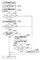
次に、図3〜図8を参照して、本発明の第1の実施の形態に係る燃料電池システムの電力制御装置の動作を説明する。なお、図3は、メイン制御フローを表すフローチャートである。図4は、出力保持判定処理の詳細を表すサブルーチンのフローチャートである。図5は、出力保持解除判定処理の詳細を表すサブルーチンのフローチャートである。図6は、スタックの電流−電圧特性を示すグラフである。図7は、要求電力量が増加する場合のスタック出力電力(a)、スタック電圧(b)、排水素量(c)の時間変化の一例を示した図である。図8は、要求電力量が減少する場合のスタック出力電力(a)、スタック電圧(b)、排水素量(c)の時間変化の一例を示した図である。
【0026】
まず、図3において、ステップS10では、スタック7から引き出す電力を要求電力値の変化に関わらず一定値に保持するか否かを判定する。ここで、図4に示すサブルーチンを参照して、出力保持判定処理について詳細に説明する。
【0027】
図4に移り、まず、ステップS110では、DC/DCコンバータ21の入力電圧及び出力電圧を電圧検出部23,25でそれぞれ検出する。
次に、ステップS120では、検出された入力電圧Vin及び出力電圧Vout の電圧差に対して絶対値を求め、予め定められた基準値ΔV未満かどうかを判定する。すなわち、入出力電圧差が基準範囲(−ΔV〜ΔV)内にあるかどうかを判定する。
【0028】
|Vin−Vout |≦ΔV
なお、上述した判断に用いられる基準値ΔVは、制御系の検出誤差により昇降圧判断を誤る程度の電圧幅より大きく設定することが望ましい。すなわち、DC/DCコンバータ21の入出力電圧の大小関係が逆転することが考えられる境界領域に対して、電圧検出部23,25による入出力電圧の検出誤差により両者がほぼ等しくなっている時間や、システム制御部15を構成するCPU内のA/Dコンバータが分解能以下となる時間などをサンプリング周期以下となるように設定することが望ましい。
【0029】
そして、DC/DCコンバータ21の入出力電圧差の絶対値が基準値ΔV以上の場合には、スタック7から引き出す電力を一定値に保持する必要がないと判断し、保持フラグをセットすることなく、本サブルーチンを終了する。なお、スタック7から引き出す電力指令値は、アクセル開度やブレーキ踏力、負荷となる例えばインバータや駆動用モータ(図示せず)やシステム機器から要求される電力量と、電力貯蔵部11の充放電可能量を考慮して求められたスタック7に要求される全電力の指令値であり、本実施の形態では、システム制御部15により算出されることとする。
【0030】
一方、ステップS130では、この入出力電圧差の絶対値が基準値ΔV未満の場合には、入出力電圧の大小関係がしばらく後に逆転する可能性がある境界領域にあるので、スタック7から引き出す電力指令値を保持するため、保持フラグをセット(1)する。
【0031】
次に、図3に移り、ステップS20では、保持されている電力指令値を維持すべきか、解除すべきかを判定する。ここで、図5に示すサブルーチンを参照して、出力保持解除判定処理について詳細に説明する。
まず、ステップS210では、DC/DCコンバータ21の出力電圧Vout を電圧検出部25で検出する。
【0032】
そして、ステップS220では、電力指令値の保持を解除した時にスタック7からDC/DCコンバータ21へ入力される入力電圧、すなわち、スタック7の出力電圧を推定する。具体的には、電力指令値の保持を継続するとともに、元々要求されている電力指令値を監視し、その電力をスタック7から引き出した時の電圧値Vin’を図6に示す電流−電圧特性を参照して推定する。
【0033】
なお、スタック7の電流−電圧特性は、図6に示すように、電流Iの増加に伴い電圧Vが降下する傾向を示している。図6は、発電に必要な水素及び空気が十分供給されている場合の例である。また、スタック7に供給される水素量や空気量または両者の圧力を用いて、図6に示す電流−電圧特性を補正してもよいが、本発明とは直接関係がないのでその詳細な説明を省略する。
【0034】
そして、ステップS230では、DC/DCコンバータ21の出力電圧Vout と、推定した入力電圧Vin’との電圧差の絶対値を求め、予め定められた基準値ΔV未満かどうかを判定する。
この電圧差が基準値ΔV以上の場合には、スタック7から引き出す電力指令値の保持を維持する必要がないと判断し、ステップS300では、保持フラグをクリア(0)する。
【0035】
一方、入出力電圧差が基準値ΔV未満の場合には、まだ電力指令値の保持を解除する必要がないと判定し、ステップS240に進む。
ステップS240では、改質器3内の排水素燃焼器(図示せず)に設けられた温度センサ17により排水素燃焼器の温度Tを検出する。
【0036】
なお、排水素燃焼器は、スタック7で消費されなかった排水素を燃焼して改質器3内の温度を保っており、スタック7で消費される水素量をある一定値で保持し、その結果、スタック7から引き出す電力をある一定値で保持している。
【0037】
さて、改質器3の応答速度は、スタック7や他の負荷よりも一般的に遅いので出力保持を解除した時点で、スタック7から十分な出力を引き出せるよう、改質器3で発生させる水素量をスタック7で消費される水素量に関わらず、燃料電池システムとして要求される電力に応じて変化させることを考える。この場合、スタック7で消費されない排水素量が、排水素燃焼器で燃焼を予定している所要量と差異が生じることになり、排水素量が過剰な場合、排水素燃焼器の温度Tは上昇傾向となり、また、排水素量が不足の場合、温度Tは下降気味となる。
【0038】
そこで、ステップS250では、温度センサ17により検出された排水素燃焼器の温度Tが、予め定められた下限温度Tlow から上限温度Thiまでの範囲を超えるかどうかを判定する。
【0039】
Tlow ≦ T ≦ Thi
排水素燃焼器の温度Tがこの範囲を超えると判定された場合には、ステップS300に進み、電力指令値の保持フラグをクリア(0)し、そして、スタック7は要求電力値に応じて発電して水素量を消費することで、排水素燃焼器へ入る水素量を元に戻し、温度Tがこの範囲を超えることを防止する。
【0040】
図7(b)に示すように、スタック電圧(入力電圧)がバッテリ電圧(出力電圧)に近づいた時間t1で、スタック7から引き出す電流を一定値に制御し始める。この場合、図7(b)に示すように、スタック7で消費される水素量が一定値になり、改質器3は要求電力量に応じて水素を発生するようになるため、排水素量が増加する。さらに、時間t2で保持フラグがクリア(0)されて出力保持が解除され、要求電力量をスタック7から引き出すと、電圧がその電力値に応じて低下し、また水素消費量も増加するので、図7(c)に示すように、排水素量も元に近い値に戻ることになる。
【0041】
また、図8(b)に示すように、スタック電圧(入力電圧)がバッテリ電圧(出力電圧)に近づいた時間t3で、スタック7から引き出す電流を一定値に制御し始める。この場合、図8(b)に示すように、スタック7で消費される水素量が一定量になり、改質器3は要求電力量に応じて発生水素量を減じるようにするため、排水素量が減少する。さらに、時間t4で保持フラグがクリア(0)されて出力保持が解除され、要求電力量をスタック7から引き出すと、電圧がその電力値に応じて低下し、また水素消費量も減少するので、図8(c)に示すように、排水素量も元に近い値に戻ることになる。
【0042】
図5に移り、ステップS260では、要求電力が保持決定後も引き続き同傾向にあるかどうかを判定する。すなわち、DC/DCコンバータ21の入出力電圧の大小関係が交差すると予想判定した後に、要求電力値の変化方向が反転し、交差することがなくなるかどうかを推定する。
【0043】
具体的には、要求電力変化量の時間変化を算出し、今回値と前回値とが同一符号、すなわち、引き続き増加あるいは減少している場合には、スタック電圧もそれぞれ減少傾向または増加傾向が続くと判断し、保持フラグをクリアせずに、スタック7からの電力を保持し続ける。
【0044】
符号が反転していた場合、スタック7からの電力保持の解除を判断するため、ステップS270では、保持解除時点でのスタック電圧を推定する。なお、本ステップの内容は上述したステップS220と同様である。
【0045】
そして、ステップS280では、既に入出力電圧が交差したかどうかを判定する。既に交差済みだった場合には再び交差するまで保持を継続する。
そして、入出力電圧の大小関係がまだ交差していないと推定された場合には、次に、ステップS290へと進み、保持フラグをクリア(0)して解除するかどうかを判定する。すなわち、このステップS280は、要求電力値の変化方向が反転し、スタック電圧の変化傾向も反転する場合、入出力電圧の大小関係がそのまま変化しないと考えられるため、一度入出力電圧の大小関係が反転してしまっている場合には再度反転し、元の関係に戻るのを待つようにする。
【0046】
ステップS290では、出力電圧Vout と推定した入力電圧Vin’との電圧差の絶対値が予め定められた基準値ΔV以内かどうかを判定する。入出力電圧差の絶対値が基準値を超える場合には、ステップS300に進み、出力保持フラグをクリア(0)して解除し、図3に示すメインルーチンに復帰する。
【0047】
一方、入出力電圧差の絶対値が基準値以下の場合には、そのまま図3に示すメインルーチンに復帰する。
図3に移り、ステップS30では、保持フラグがセット状態(1)かどうかを判定し、保持フラグが(1)の場合にはステップS40に進み、出力保持制御を行い、入出力電圧の大小関係が元に戻るのを待つ。
【0048】
一方、保持フラグがセット状態(1)ではない場合にはステップS50に進み、通常制御を行い、処理を終了する。すなわち、通常制御としては、DC/DCコンバータ21の入出力側に設けられた電圧検出部23,25で検出される入力電圧Vinと出力電圧Vout を比較する。
【0049】
Vin < Vout
となり、入力電圧Vinの方が出力電圧Vout より低い場合には、DC/DCコンバータ21に昇圧動作を行せるため、CNT1によりトランジスタTr1をON制御した状態で、所望の電流Iが流れるように、あるデューティ比の矩形波からなるCNT3をトランジスタTr3に出力してスイッチング動作させる。この結果、トランジスタTr3がON制御時に、スタック7から入力される電力がインダクタL1に充電され、トランジスタTr3がOFF制御時に、インダクタL1から電力が放電されてコンデンサC3の端子間電圧に加わり昇圧される。
【0050】
一方、入力電圧Vinと出力電圧Vout を比較して、Vin > Voutとなり、入力電圧Vinの方が出力電圧Vout より高い場合には、DC/DCコンバータ21に降圧動作を行せるため、まず、CNT3によりトランジスタTr3をOFF制御し、所望の電流Iが流れるように、あるデューティ比の矩形波からなるCNT1をトランジスタTr1に出力してスイッチング動作させる。この結果、トランジスタTr1がON制御時に、スタック7から入力される電力がインダクタL1、ダイオードD3を介してコンデンサC3に充電され、トランジスタTr1がOFF制御時に、コンデンサC3から電力が放電されてコンデンサC3の端子間電圧が降圧される。
【0051】
第1の実施の形態に関する効果は、DC/DCコンバータ21の入力側および出力側の入力電圧および出力電圧を電圧検出部23,25で検出するようにしておき、検出された入力電圧と出力電圧との電圧差が所定の範囲内にある場合に、スタック7の出力電圧を一定値に固定するように制御することで、DC/DCコンバータ21が昇圧変換と降圧変換との切替領域で動作しているときでも一方の変換動作により出力電圧を固定することができる。この結果、切替制御の判断情報となる入出力電圧やスタック電流等の検出誤差によって、適切な切替制御が阻害されることを防止でき、十分な運転性能を引き出すことができる。
【0052】
また、スタック7の出力電流を一定値になるように制御することで、スタック7の出力電圧を一定値に固定することができる。
また、DC/DCコンバータ21は、スタック7の出力電圧を一定値に固定した後に、スタック7に所望される出力としたときの出力電圧を推定し、この推定出力電圧とDC/DCコンバータ21の出力電圧値との電圧差が所定値以上の場合には、スタック7の出力電圧を一定値に固定する制御を解除することで、DC/DCコンバータ21が一方の変換動作から他方の変換動作に移行することができる。
【0053】
また、改質器3に設けられスタック7から排出される排水素を排水素燃焼器で燃焼するようにしておき、排水素燃焼器の温度を温度センサ17で検出しておく。ここで、排水素燃焼器の温度が所定の温度範囲以外にある場合に、スタック7の出力電圧を一定値に固定する制御を解除することで、スタック7は要求電力値に応じて発電して水素量を消費することで、排水素燃焼器へ入る水素量を元に戻し、排水素燃焼器の温度が予め定められた範囲を超えることを防止することができる。
【0054】
(第2の実施の形態)
本発明の第2の実施の形態に係る燃料電池システムの電力制御装置は、図1に示す第1の実施の形態に対応する燃料電池システムの電力制御装置と同様の基本的構成を有しており、その説明を省略することとする。
【0055】
次に、図9に示す出力保持解除判定処理に関するサブルーチンのフローチャートに従って電力制御装置の制御動作の一部を説明する。なお、図9に示す制御フローチャートは、図5に示す制御フローチャートと同様の基本的手順を有しており、同一の手順には同一の符号を付している。また、図9に示す制御フローチャートも、システム制御部15の内部ROMに制御プログラムとして記憶されている。
【0056】
図8(a)に示すように、要求電力値が減少傾向にある時に、スタック7からの出力を保持する場合、スタック7からの排水素量が減少する。これは改質器3で改質された水素が要求電力量に応じて減じる一方で、スタック7の出力電力をある一定値に保持するため、スタック7に供給される水素に対し電力に変換された割合、すなわち、消費した水素の割合(以下、水素利用率という)が増加することによる。
【0057】
この水素利用率がある限度を超えると、スタック7を構成するセル全てに均等に水素の圧力や量が配分されないなどの理由により、スタック7の出力電圧が低下するなどの電圧特性が低下してしまう場合が考えられる。
【0058】
そこで、第2の実施の形態の特徴は、この水素利用率が限度を超えて上昇することを防止する点にある。
詳しくは、図9において、ステップS253では、水素利用率Srを算出する。すなわち、図1に示す改質器3からスタック7に供給される水素経路、スタック7から排出される排水素の水素経路にそれぞれ水素流量計(図示せず)を設け、両検出値の流量差から利用率Srを算出する。
【0059】
そして、ステップS255では、算出された水素利用率Srが予め定められた基準値Sr’を超えたかどうかを判断する。ここで、水素利用率Srが予め定められた基準値Sr’を超えた場合には、ステップS300に進み、スタック7の出力保持フラグをクリア(0)して解除する。
【0060】
一方、水素利用率Srが予め定められた基準値Sr’を超えてなければ出力保持フラグはセット状態(1)に継続して保持される。
なお、ステップS253,S255に代わって、スタック7の出力電圧の変化を検出して水素利用率が限度を超えて上昇したことを推定してもよい。これはスタック7の出力電流を一定値に維持している場合で、十分な水素量がスタック7に供給されているときに、スタック7の出力電圧も一定値に維持されているので、改質器3から供給される水素量が相対的に減少すると、スタック7の出力電圧が低下するなどの電圧特性が変化することを利用するものである。
【0061】
スタック7の出力保持中にスタックの出力電圧、すなわち、DC/DCコンバータ21の入力電圧Vinの変化を検出し、予め定められた値以上の低下幅を検出した場合、水素利用率Srがある限度を超えて上昇したと判断する。
なお、ステップS253&S255において、水素利用率Srが予め定められた基準値Sr’を超えたと判断した場合に、スタック7の出力保持フラグをクリア(0)して解除するように選択しているが、改質器3からスタック7に供給される水素量をその時点での水素量に維持してもよい。
【0062】
具体的には、スタック7の出力保持を解除するときの判断に用いる水素利用率Srより小さい閾値Sr”を別途に設定しておき、水素利用率Srがこの閾値を超えたと判断したときに、改質器3を要求電力値に応じて制御するのを一旦停止し、その時点での水素生成量で改質器3の運転を継続する。これにより水素利用率Srを前記閾値Sr”前後の値に保つことが可能となり、スタック7の出力保持を継続することができる。
【0063】
スタック7の出力電圧で水素利用率Srを推定する場合は、スタック出力保持解除を判断するための電圧の変化幅より小さい電圧変化幅の閾値を別途設定し、この閾値を超えた時点の水素生成量を保つことで表現される。この場合の改質器3の制御は、スタック7の出力保持が解除された時点で、生成量の目標値をシステムから求まる要求電力値に応じた値に戻すのが適当である。
【0064】
第2の実施の形態に関する効果は、第1の実施の形態に関する効果に加えて、スタック7の入力側および出力側の水素量を検出しておき、検出された水素量に基づいて、スタック7での水素利用率を算出し、この水素利用率が所定値を超えた場合に、スタック7の出力電圧を一定値に固定する制御を解除することで、DC/DCコンバータ21が一方の変換動作から他方の変換動作に移行することができる。
【図面の簡単な説明】
【図1】本発明の第1の実施の形態に係る燃料電池システムの電力制御装置のシステム構成を示す図である。
【図2】電力制御部9を構成するDC/DCコンバータ21の具体的構成を示す図である。
【図3】メイン制御フローを表すフローチャートである。
【図4】出力保持判定処理の詳細を表すサブルーチンのフローチャートである。
【図5】出力保持解除判定処理の詳細を表すサブルーチンのフローチャートである。
【図6】スタックの電流−電圧特性を示すグラフである。
【図7】要求電力量が増加する場合のスタック出力電力(a)、スタック電圧(b)、排水素量(c)の時間変化の一例を示した図である。
【図8】要求電力量が減少する場合のスタック出力電力(a)、スタック電圧(b)、排水素量(c)の時間変化の一例を示した図である。
【図9】出力保持解除判定処理の詳細を表すサブルーチンのフローチャートである。
【図10】従来のDC/DCコンバータの具体的構成を示す図である。
【図11】従来のDC/DCコンバータを構成するトランジスタTr101,Tr103のベースに加える制御信号のデューティ比と昇降圧比との関係を示すグラフである。
【符号の説明】
1 燃料タンク
3 改質器
5 コンプレッサ
7 スタック
9 電力制御部
11 電力貯蔵部
13 負荷
15 システム制御部
17 温度センサ
21 DC/DCコンバータ
23,25 電圧検出部[0001]
BACKGROUND OF THE INVENTION
The present invention relates to an output control device for a fuel cell system, and to provide an output control device for a fuel cell system that can optimally supply power generated by the fuel cell to a load system and draw out sufficient operation performance. is there.
[0002]
[Prior art]
In a fuel cell vehicle configured to supply electric power generated by the fuel cell system to a drive motor, the output of the fuel cell generally changes in accordance with the operation of the driver. At the same time, in order to generate power to be supplied to the drive motor in the stack, the amount of hydrogen generated in the reformer is controlled to change, but the response speed of the reformer tends to be slower than the load fluctuation.
[0003]
For this reason, when electric power is drawn from the stack in accordance with an increase in load due to the drive motor, the amount of hydrogen supplied to the stack becomes insufficient, causing a problem that the stack voltage drops abnormally.
Therefore, power corresponding to the amount of hydrogen and air supplied to the stack is drawn out, and there is an excess or shortage of the response delay by the stack, that is, the power from the stack and the power required by the load. The power difference is absorbed by charging / discharging from the secondary battery.
[0004]
Conventionally, in an output control device of a fuel cell system mounted on a fuel cell vehicle, a buck-boost type DC / DC converter 121 having a basic configuration as shown in FIG. It is placed between the stack and the load.
In this DC / DC converter 121, the switching elements to be operated are different in step-up conversion and step-down conversion, and a desired voltage is generated according to the duty ratio of the control signal applied to the bases of the transistors Tr101 and Tr103. Yes. FIG. 11 is a graph showing the relationship between the duty ratio of the control signal applied to the bases of the transistors Tr101 and Tr103 and the step-up / step-down ratio.
[0005]
At the time of boosting, an ON control signal (1) is added to the
On the other hand, at the time of step-down, an OFF control signal (0) is added to the
[0006]
[Problems to be solved by the invention]
However, as shown in FIG. 11, the output voltage that can be extracted from the DC / DC converter 121 does not always have continuity. In particular, when the input / output voltages are substantially equal and when switching from step-up conversion to step-down conversion, or when switching from step-down conversion to step-up conversion, it is considered difficult to stably convert power by the DC / DC converter 121. It is done.
[0007]
That is, when a voltage sensor is used to detect the voltage of a secondary battery or a load provided on the output side of the DC / DC converter 121, the sensor itself has a certain detection error, and the sensor output Even if the signal is input to the A / D converter and quantized, the resolution and error of the A / D converter itself are added. For this reason, for example, even if the voltage of the secondary battery or load is compared with the output voltage from the stack, and the conversion function of the DC / DC converter 121 is switched based on the magnitude relationship between them, the detection error described above is added. Since an error occurs in the switching determination, it is conceivable that an appropriate conversion function cannot be selected.
[0008]
As described above, in the switching boundary region between step-up conversion and step-down conversion of the DC / DC converter, appropriate switching control may be hindered by detection errors such as input / output voltage and stack current as determination information for switching control. As a result, it may be difficult to ensure the desired driving performance.
[0009]
The present invention has been made in view of the above, and an object of the present invention is to provide an output control device for a fuel cell system that can optimally supply the power generated by the fuel cell to the load system and extract sufficient operating performance. Is to provide.
[0010]
[Means for Solving the Problems]
In order to solve the above problems, the invention according to claim 1 An output control device for a fuel cell system mounted on a fuel cell vehicle, Using a reformer that reforms fuel to generate a reformed gas containing hydrogen, a compressor that compresses air, a reformed gas supplied from the reformer, and an air supplied from the compressor A fuel cell for generating power, a power control means for boosting or stepping down the power output from the fuel cell in accordance with a request command, a power storage means for storing the power output from the power control means, and a power storage means A voltage detection means for detecting an input voltage and an output voltage on the input side and the output side of the power control means, comprising a load connected in parallel and consuming electric power output from the power control means in accordance with an operation state; Calculation means for calculating a voltage difference between the input voltage and the output voltage detected by the voltage detection means; A fixed control means having a function of fixing the output voltage of the fuel cell to a constant value and a function of releasing the fixation of the output voltage of the fuel cell, the fixed control means being an input voltage detected by the voltage detection means The output voltage of the fuel cell is fixed to a constant value when the voltage difference calculated by the calculation means is within a predetermined range. This is the gist.
[0011]
In order to solve the above problems, the invention according to
[0012]
According to a third aspect of the present invention, in order to solve the above-mentioned problem, the power control means sets an output voltage when the output voltage of the fuel cell is set to a desired value after fixing the output voltage of the fuel cell to a constant value. Voltage estimation means for estimation; voltage difference calculation means for calculating a voltage difference between the estimated output voltage estimated by the voltage estimation means and the output voltage value of the power control means; and calculated by the voltage difference calculation means When the voltage difference is equal to or larger than a predetermined value, the gist is to cancel the control for fixing the output voltage of the fuel cell to a constant value.
[0013]
In order to solve the above problems, the invention according to claim 4 is an exhaust hydrogen combustor that is provided in the reformer and combusts hydrogen discharged from a fuel cell, and a temperature detection means that detects the temperature of the exhaust hydrogen combustor. The fixing control means is configured to release the control for fixing the output voltage of the fuel cell to a constant value when the temperature of the exhaust hydrogen combustor is outside a predetermined temperature range.
[0014]
In order to solve the above problems, the invention according to
[0015]
【The invention's effect】
According to the first aspect of the present invention, the input voltage and the output voltage on the input side and the output side of the power control means are detected, and the voltage difference between the detected input voltage and the output voltage is within a predetermined range. By controlling so that the output voltage of the fuel cell is fixed at a constant value, the power control means outputs by one conversion operation even when operating in the switching region between step-up conversion and step-down conversion. The voltage can be fixed. As a result, it is possible to prevent the appropriate switching control from being hindered by detection errors such as input / output voltage and stack current, which are judgment information of the switching control, and to draw out sufficient driving performance.
[0016]
According to the second aspect of the present invention, the output voltage of the fuel cell can be fixed to a constant value by controlling the output current of the fuel cell to be a constant value.
[0017]
According to the third aspect of the present invention, the power control means estimates the output voltage when the output desired by the fuel cell is obtained after fixing the output voltage of the fuel cell to a constant value. When the voltage difference between the output voltage and the output voltage value of the power control means is greater than or equal to a predetermined value, the power control means is controlled from one conversion operation by releasing the control for fixing the output voltage of the fuel cell to a constant value. It is possible to shift to the other conversion operation.
[0018]
According to the fourth aspect of the present invention, the hydrogen provided in the reformer and discharged from the fuel cell is burned in the exhaust hydrogen combustor, and the temperature of the exhaust hydrogen combustor is detected. . Here, when the temperature of the exhaust hydrogen combustor is outside the predetermined temperature range, the fuel cell generates power according to the required power value by canceling the control for fixing the output voltage of the fuel cell to a constant value. By consuming the amount of hydrogen, the amount of hydrogen entering the exhaust hydrogen combustor can be restored, and the temperature of the exhaust hydrogen combustor can be prevented from exceeding a predetermined range.
[0019]
Further, according to the present invention of
[0020]
DETAILED DESCRIPTION OF THE INVENTION
Hereinafter, embodiments of the present invention will be described with reference to the drawings.
(First embodiment)
FIG. 1 is a diagram showing a system configuration of a power control device of a fuel cell system according to a first embodiment of the present invention.
[0021]
In FIG. 1, methanol serving as fuel is stored in a
[0022]
The remaining exhaust hydrogen that is not used for the reaction in the
The current generated from the
[0023]
The
The
[0024]
FIG. 2 is a diagram showing a specific configuration of the DC /
On the input side and the output side of the DC /
[0025]
Next, the operation of the power control apparatus of the fuel cell system according to the first embodiment of the present invention will be described with reference to FIGS. FIG. 3 is a flowchart showing the main control flow. FIG. 4 is a flowchart of a subroutine showing details of the output holding determination process. FIG. 5 is a flowchart of a subroutine showing details of the output hold release determination process. FIG. 6 is a graph showing current-voltage characteristics of the stack. FIG. 7 is a diagram illustrating an example of temporal changes in the stack output power (a), the stack voltage (b), and the exhausted hydrogen amount (c) when the required power amount increases. FIG. 8 is a diagram illustrating an example of temporal changes in the stack output power (a), the stack voltage (b), and the exhausted hydrogen amount (c) when the required power amount decreases.
[0026]
First, in FIG. 3, in step S10, it is determined whether or not the power drawn from the
[0027]
Turning to FIG. 4, first, in step S110, the input voltage and the output voltage of the DC /
Next, in step S120, an absolute value is obtained with respect to the detected voltage difference between the input voltage Vin and the output voltage Vout, and it is determined whether or not it is less than a predetermined reference value ΔV. That is, it is determined whether or not the input / output voltage difference is within the reference range (−ΔV to ΔV).
[0028]
| Vin−Vout | ≦ ΔV
It is desirable that the reference value ΔV used for the above-described determination is set to be larger than a voltage width at which the step-up / step-down determination is erroneous due to the detection error of the control system. That is, with respect to a boundary region where the magnitude relationship between the input / output voltages of the DC /
[0029]
When the absolute value of the input / output voltage difference of the DC /
[0030]
On the other hand, in step S130, when the absolute value of this input / output voltage difference is less than the reference value ΔV, the magnitude relationship between the input and output voltages is in a boundary region that may be reversed after a while. In order to hold the command value, a holding flag is set (1).
[0031]
Next, moving to FIG. 3, in step S20, it is determined whether the held power command value should be maintained or released. Here, the output hold release determination processing will be described in detail with reference to the subroutine shown in FIG.
First, in step S210, the
[0032]
In step S220, the power command value is held. Canceled The input voltage input from the
[0033]
The current-voltage characteristic of the
[0034]
In step S230, the absolute value of the voltage difference between the output voltage Vout of the DC /
If this voltage difference is greater than or equal to the reference value ΔV, it is determined that it is not necessary to maintain the power command value drawn from the
[0035]
On the other hand, if the input / output voltage difference is less than the reference value ΔV, it is determined that it is not necessary to cancel the holding of the power command value, and the process proceeds to step S240.
In step S240, the
[0036]
The exhaust hydrogen combustor burns the exhaust hydrogen that has not been consumed in the
[0037]
Since the response speed of the
[0038]
Therefore, in step S250, the temperature T of the exhaust hydrogen combustor detected by the
[0039]
Tlow ≤ T ≤ Thi
If it is determined that the temperature T of the exhaust hydrogen combustor exceeds this range, the process proceeds to step S300, the power command value holding flag is cleared (0), and the
[0040]
As shown in FIG. 7B, at time t1 when the stack voltage (input voltage) approaches the battery voltage (output voltage), the current drawn from the
[0041]
Further, as shown in FIG. 8B, at time t3 when the stack voltage (input voltage) approaches the battery voltage (output voltage), the current drawn from the
[0042]
Turning to FIG. 5, in step S260, it is determined whether or not the required power continues to have the same tendency after the holding decision. That is, after predicting that the magnitude relationship between the input / output voltages of the DC /
[0043]
Specifically, the time change of the required power change amount is calculated, and when the current value and the previous value have the same sign, that is, when it continues to increase or decrease, the stack voltage also continues to decrease or increase, respectively. Therefore, the power from the
[0044]
If the sign is inverted, in order to determine whether to release the power holding from the
[0045]
In step S280, it is determined whether the input / output voltages have already crossed. If already crossed, keep holding until crossing again.
If it is estimated that the magnitude relationship between the input and output voltages has not yet crossed, the process proceeds to step S290, where it is determined whether the retention flag is cleared (0) to be released. That is, in step S280, when the change direction of the required power value is reversed and the change tendency of the stack voltage is also reversed, the magnitude relationship between the input and output voltages is considered to remain unchanged. If it has been reversed, it is reversed again and waits for the original relationship to return.
[0046]
In step S290, it is determined whether or not the absolute value of the voltage difference between the output voltage Vout and the estimated input voltage Vin ′ is within a predetermined reference value ΔV. If the absolute value of the input / output voltage difference exceeds the reference value, the process proceeds to step S300, where the output hold flag is cleared (0) to be released, and the process returns to the main routine shown in FIG.
[0047]
On the other hand, when the absolute value of the input / output voltage difference is equal to or smaller than the reference value, the process directly returns to the main routine shown in FIG.
Turning to FIG. 3, in step S30, it is determined whether or not the holding flag is in the set state (1). If the holding flag is (1), the process proceeds to step S40, output holding control is performed, and the magnitude relationship between the input and output voltages. Wait for it to return.
[0048]
On the other hand, if the holding flag is not in the set state (1), the process proceeds to step S50, where normal control is performed, and the process ends. That is, as the normal control, the input voltage Vin detected by the
[0049]
Vin <Vout
When the input voltage Vin is lower than the output voltage Vout, the DC /
[0050]
On the other hand, when the input voltage Vin and the output voltage Vout are compared, Vin> Vout, and when the input voltage Vin is higher than the output voltage Vout, the DC /
[0051]
The effect of the first embodiment is that the input and output voltages on the input side and output side of the DC /
[0052]
Further, by controlling the output current of the
Further, the DC /
[0053]
Further, the exhaust hydrogen provided in the
[0054]
(Second Embodiment)
The power control apparatus of the fuel cell system according to the second embodiment of the present invention has the same basic configuration as the power control apparatus of the fuel cell system corresponding to the first embodiment shown in FIG. The description thereof will be omitted.
[0055]
Next, a part of the control operation of the power control apparatus will be described with reference to a flowchart of a subroutine related to the output hold release determination process shown in FIG. The control flowchart shown in FIG. 9 has the same basic procedure as the control flowchart shown in FIG. 5, and the same procedure is denoted by the same reference numeral. 9 is also stored in the internal ROM of the
[0056]
As shown in FIG. 8A, when the output from the
[0057]
If this hydrogen utilization rate exceeds a certain limit, the voltage characteristics such as the output voltage of the
[0058]
Therefore, the feature of the second embodiment is that this hydrogen utilization rate is prevented from rising beyond the limit.
Specifically, in FIG. 9, in step S253, the hydrogen utilization rate Sr is calculated. That is, a hydrogen flow meter (not shown) is provided in each of the hydrogen path supplied to the
[0059]
In step S255, it is determined whether or not the calculated hydrogen utilization rate Sr exceeds a predetermined reference value Sr ′. Here, when the hydrogen utilization rate Sr exceeds a predetermined reference value Sr ′, the process proceeds to step S300, and the output holding flag of the
[0060]
On the other hand, if the hydrogen utilization rate Sr does not exceed the predetermined reference value Sr ′, the output holding flag is continuously held in the set state (1).
Instead of steps S253 and S255, a change in the output voltage of the
[0061]
When a change in the stack output voltage, that is, the input voltage Vin of the DC /
In Steps S253 & S255, when it is determined that the hydrogen utilization rate Sr has exceeded a predetermined reference value Sr ′, the output holding flag of the
[0062]
Specifically, when a threshold value Sr ″ smaller than the hydrogen utilization rate Sr used for determination when releasing the output hold of the
[0063]
When the hydrogen utilization rate Sr is estimated from the output voltage of the
[0064]
The effect related to the second embodiment is that, in addition to the effect related to the first embodiment, the amounts of hydrogen on the input side and output side of the
[Brief description of the drawings]
FIG. 1 is a diagram showing a system configuration of a power control apparatus of a fuel cell system according to a first embodiment of the present invention.
FIG. 2 is a diagram showing a specific configuration of a DC /
FIG. 3 is a flowchart showing a main control flow.
FIG. 4 is a flowchart of a subroutine representing details of output holding determination processing.
FIG. 5 is a flowchart of a subroutine showing details of output hold release determination processing.
FIG. 6 is a graph showing current-voltage characteristics of a stack.
FIG. 7 is a diagram illustrating an example of temporal changes in stack output power (a), stack voltage (b), and exhaust hydrogen amount (c) when the required power amount increases.
FIG. 8 is a diagram illustrating an example of temporal changes in stack output power (a), stack voltage (b), and exhaust hydrogen amount (c) when the required power amount decreases.
FIG. 9 is a subroutine flowchart showing details of output hold release determination processing;
FIG. 10 is a diagram showing a specific configuration of a conventional DC / DC converter.
FIG. 11 is a graph showing a relationship between a duty ratio of a control signal applied to the bases of transistors Tr101 and Tr103 constituting a conventional DC / DC converter and a step-up / step-down ratio.
[Explanation of symbols]
1 Fuel tank
3 Reformer
5 Compressor
7 stacks
9 Power control unit
11 Power storage unit
13 Load
15 System controller
17 Temperature sensor
21 DC / DC converter
23, 25 Voltage detector
Claims (5)
燃料を改質して水素を含む改質ガスを生成する改質器と、
空気を圧縮する圧縮器と、
改質器から供給される改質ガスと圧縮器から供給される空気とを用いて発電する燃料電池と、
燃料電池から出力される電力を要求指令に応じて昇圧変換または降圧変換する電力制御手段と、
電力制御手段から出力される電力を貯蔵する電力貯蔵手段と、
電力貯蔵手段と並列に接続され、電力制御手段から出力される電力を運転状況に応じて消費する負荷とを備え、
前記電力制御手段の入力側および出力側の入力電圧および出力電圧を検出する電圧検出手段と、
前記燃料電池の出力電圧を一定値に固定する機能、及び前記燃料電池の出力電圧の固定を解除する機能を有した固定制御手段と、を備え、
前記固定制御手段は、前記電圧検出手段により検出された入力電圧と出力電圧との電圧差を算出する算出手段と、算出手段により算出された電圧差が所定の範囲内にある場合に、前記燃料電池の出力電圧を一定値に固定する
ことを特徴とする燃料電池システムの出力制御装置。 An output control device for a fuel cell system mounted on a fuel cell vehicle,
A reformer that reforms the fuel to produce reformed gas containing hydrogen;
A compressor for compressing air;
A fuel cell that generates electricity using the reformed gas supplied from the reformer and the air supplied from the compressor;
Power control means for step-up conversion or step-down conversion of electric power output from the fuel cell in accordance with a request command;
Power storage means for storing power output from the power control means;
A load that is connected in parallel with the power storage means and that consumes the power output from the power control means according to the driving situation;
Voltage detection means for detecting input voltage and output voltage on the input side and output side of the power control means;
A fixing control means having a function of fixing the output voltage of the fuel cell to a constant value, and a function of releasing the fixing of the output voltage of the fuel cell;
The fixed control means calculates the voltage difference between the input voltage and the output voltage detected by the voltage detection means, and the fuel difference when the voltage difference calculated by the calculation means is within a predetermined range. An output control device for a fuel cell system, wherein the output voltage of the battery is fixed to a constant value .
前記燃料電池の出力電流を一定値になるように制御することを特徴とする請求項1記載の燃料電池システムの出力制御装置。The fixing control means includes
2. The output control apparatus for a fuel cell system according to claim 1, wherein the output current of the fuel cell is controlled to be a constant value.
前記燃料電池の出力電圧を一定値に固定した後に、前記燃料電池に所望される出力としたときの出力電圧を推定する電圧推定手段と、
電圧推定手段により推定された推定出力電圧と、
前記電力制御手段の出力電圧値との電圧差を算出する電圧差算出手段とを備え、
電圧差算出手段により算出される電圧差が所定値以上の場合には、前記燃料電池の出力電圧を一定値に固定する制御を解除することを特徴とする請求項1記載の燃料電池システムの出力制御装置。The power control means includes
Voltage estimation means for estimating an output voltage when the output desired by the fuel cell is obtained after fixing the output voltage of the fuel cell to a constant value;
An estimated output voltage estimated by the voltage estimating means;
Voltage difference calculation means for calculating a voltage difference with the output voltage value of the power control means,
2. The output of the fuel cell system according to claim 1, wherein when the voltage difference calculated by the voltage difference calculation means is greater than or equal to a predetermined value, the control for fixing the output voltage of the fuel cell to a constant value is canceled. Control device.
排水素燃焼器の温度を検出する温度検出手段とを備え、
前記固定制御手段は、
前記排水素燃焼器の温度が所定の温度範囲以外にある場合に、前記燃料電池の出力電圧を一定値に固定する制御を解除することを特徴とする請求項1に記載の燃料電池システムの出力制御装置。An exhaust hydrogen combustor that is provided in the reformer and burns hydrogen discharged from the fuel cell;
Temperature detecting means for detecting the temperature of the exhaust hydrogen combustor,
The fixing control means includes
When the temperature of the exhaust hydrogen combustor is outside a predetermined temperature range, the output of the fuel cell system according to claim 1, characterized in that release of the control for fixing the output voltage of the fuel cell at a constant value Control device.
水素量検出手段により検出された入力側および出力側の水素量に基づいて、前記燃料電池での水素利用率を算出する水素利用率算出手段を備え、
前記固定制御手段は、
前記水素利用率算出手段により算出された水素利用率が所定値を超えた場合に、前記燃料電池の出力電圧を一定値に固定する制御を解除することを特徴とする請求項1または請求項4のいずれかに記載の燃料電池システムの出力制御装置。Hydrogen amount detection means for detecting the hydrogen amount on the input side and output side of the fuel cell;
Hydrogen utilization rate calculating means for calculating a hydrogen utilization rate in the fuel cell based on the hydrogen amounts on the input side and output side detected by the hydrogen amount detection means,
The fixing control means includes
When the hydrogen utilization rate calculated by the hydrogen utilization rate calculating means exceeds a predetermined value, according to claim 1 or claim 4, characterized in that release of the control for fixing the output voltage of the fuel cell at a constant value The output control apparatus of the fuel cell system in any one of.
Priority Applications (1)
| Application Number | Priority Date | Filing Date | Title |
|---|---|---|---|
| JP2000014674A JP3843680B2 (en) | 2000-01-24 | 2000-01-24 | Output control device for fuel cell system |
Applications Claiming Priority (1)
| Application Number | Priority Date | Filing Date | Title |
|---|---|---|---|
| JP2000014674A JP3843680B2 (en) | 2000-01-24 | 2000-01-24 | Output control device for fuel cell system |
Publications (2)
| Publication Number | Publication Date |
|---|---|
| JP2001210345A JP2001210345A (en) | 2001-08-03 |
| JP3843680B2 true JP3843680B2 (en) | 2006-11-08 |
Family
ID=18542101
Family Applications (1)
| Application Number | Title | Priority Date | Filing Date |
|---|---|---|---|
| JP2000014674A Expired - Fee Related JP3843680B2 (en) | 2000-01-24 | 2000-01-24 | Output control device for fuel cell system |
Country Status (1)
| Country | Link |
|---|---|
| JP (1) | JP3843680B2 (en) |
Families Citing this family (10)
| Publication number | Priority date | Publication date | Assignee | Title |
|---|---|---|---|---|
| US7932634B2 (en) * | 2003-03-05 | 2011-04-26 | The Gillette Company | Fuel cell hybrid power supply |
| JP4742486B2 (en) * | 2003-04-10 | 2011-08-10 | 日産自動車株式会社 | Fuel cell power generation control device |
| US6991864B2 (en) * | 2003-09-23 | 2006-01-31 | Utc Fuel Cells, Llc | Storage of fuel cell energy during startup and shutdown |
| JP4622578B2 (en) * | 2005-02-24 | 2011-02-02 | トヨタ自動車株式会社 | Power system |
| JP2006286321A (en) * | 2005-03-31 | 2006-10-19 | Ricoh Co Ltd | Fuel cell system, electronic apparatus equipped with the same, and image formation device |
| JP5203570B2 (en) * | 2006-02-07 | 2013-06-05 | トヨタ自動車株式会社 | Output control method for fuel cell device |
| JP5015866B2 (en) * | 2008-06-18 | 2012-08-29 | 本田技研工業株式会社 | DC / DC converter device, power system, fuel cell vehicle, and physical value input method for controller of DC / DC converter device |
| CN103612571B (en) * | 2013-11-29 | 2016-01-20 | 东风小康汽车有限公司重庆分公司 | Electric automobile storage battery failure emergency control system |
| JP6063419B2 (en) * | 2014-07-03 | 2017-01-18 | 本田技研工業株式会社 | Power supply system and fuel cell vehicle |
| CN111566893B (en) * | 2018-05-15 | 2024-01-30 | Oppo广东移动通信有限公司 | Device to be charged and charging control method |
-
2000
- 2000-01-24 JP JP2000014674A patent/JP3843680B2/en not_active Expired - Fee Related
Also Published As
| Publication number | Publication date |
|---|---|
| JP2001210345A (en) | 2001-08-03 |
Similar Documents
| Publication | Publication Date | Title |
|---|---|---|
| US8153313B2 (en) | Hybrid voltage supply apparatus, method of controlling the same, and electronic system employing the same as power supply | |
| EP2237351B1 (en) | Method of controlling output of fuel cell system and vehicle with fuel cell system | |
| US7939213B2 (en) | Fuel cell system and electric vehicle including the fuel cell system | |
| JP5750341B2 (en) | Fuel cell system | |
| JP3843680B2 (en) | Output control device for fuel cell system | |
| US8084151B2 (en) | Fuel cell system and method therefor | |
| US20060240291A1 (en) | Power supply apparatus using fuel cell and method of controlling the same | |
| JP2006311776A (en) | Multiple-phase voltage converter and vehicle | |
| JP2004146114A (en) | Fuel cell system | |
| JP2005166673A (en) | Load following algorithm for fuel cell based system | |
| JP2007165055A (en) | Fuel cell system and operation stop method of fuel cell system | |
| JP4111059B2 (en) | Voltage conversion system, voltage conversion method, and control program | |
| JP2008017594A (en) | Control device for vehicles mounted with fuel cell | |
| US9623766B2 (en) | Control method of fuel cell system, fuel cell automobile, and fuel cell system | |
| JP5651531B2 (en) | Fuel cell vehicle | |
| JP2006210100A (en) | Power supply device | |
| JP3651927B2 (en) | Load control device for fuel cell power generator | |
| JP2009171735A (en) | Dc/dc converter | |
| JP2016152227A (en) | Fuel battery system | |
| JP6174528B2 (en) | Control method for fuel cell system with two power loads and fuel cell vehicle | |
| JP5986977B2 (en) | Power system | |
| JP2001025105A (en) | Power controller of fuel cell car | |
| JP6724585B2 (en) | Fuel cell system | |
| JP5651528B2 (en) | Fuel cell system | |
| JP6167864B2 (en) | FUEL CELL SYSTEM, FUEL CELL VEHICLE, AND METHOD FOR CONTROLLING FUEL CELL SYSTEM |
Legal Events
| Date | Code | Title | Description |
|---|---|---|---|
| A131 | Notification of reasons for refusal |
Free format text: JAPANESE INTERMEDIATE CODE: A131 Effective date: 20040727 |
|
| A521 | Written amendment |
Free format text: JAPANESE INTERMEDIATE CODE: A523 Effective date: 20040922 |
|
| TRDD | Decision of grant or rejection written | ||
| A01 | Written decision to grant a patent or to grant a registration (utility model) |
Free format text: JAPANESE INTERMEDIATE CODE: A01 Effective date: 20060725 |
|
| A61 | First payment of annual fees (during grant procedure) |
Free format text: JAPANESE INTERMEDIATE CODE: A61 Effective date: 20060807 |
|
| R150 | Certificate of patent or registration of utility model |
Free format text: JAPANESE INTERMEDIATE CODE: R150 |
|
| LAPS | Cancellation because of no payment of annual fees |