JP2006286321A - Fuel cell system, electronic apparatus equipped with the same, and image formation device - Google Patents
Fuel cell system, electronic apparatus equipped with the same, and image formation device Download PDFInfo
- Publication number
- JP2006286321A JP2006286321A JP2005102853A JP2005102853A JP2006286321A JP 2006286321 A JP2006286321 A JP 2006286321A JP 2005102853 A JP2005102853 A JP 2005102853A JP 2005102853 A JP2005102853 A JP 2005102853A JP 2006286321 A JP2006286321 A JP 2006286321A
- Authority
- JP
- Japan
- Prior art keywords
- fuel cell
- current
- fuel
- power storage
- cell system
- Prior art date
- Legal status (The legal status is an assumption and is not a legal conclusion. Google has not performed a legal analysis and makes no representation as to the accuracy of the status listed.)
- Pending
Links
Images


Classifications
-
- Y—GENERAL TAGGING OF NEW TECHNOLOGICAL DEVELOPMENTS; GENERAL TAGGING OF CROSS-SECTIONAL TECHNOLOGIES SPANNING OVER SEVERAL SECTIONS OF THE IPC; TECHNICAL SUBJECTS COVERED BY FORMER USPC CROSS-REFERENCE ART COLLECTIONS [XRACs] AND DIGESTS
- Y02—TECHNOLOGIES OR APPLICATIONS FOR MITIGATION OR ADAPTATION AGAINST CLIMATE CHANGE
- Y02E—REDUCTION OF GREENHOUSE GAS [GHG] EMISSIONS, RELATED TO ENERGY GENERATION, TRANSMISSION OR DISTRIBUTION
- Y02E60/00—Enabling technologies; Technologies with a potential or indirect contribution to GHG emissions mitigation
- Y02E60/30—Hydrogen technology
- Y02E60/50—Fuel cells
Landscapes
- Fuel Cell (AREA)
Abstract
Description
本発明は燃料電池システムに関し、特にアルコールを燃料とする燃料電池システムに関する。本発明はさらに、そのような燃料電池システムを備える電子機器および画像形成装置に関する。 The present invention relates to a fuel cell system, and more particularly to a fuel cell system using alcohol as a fuel. The present invention further relates to an electronic apparatus and an image forming apparatus provided with such a fuel cell system.
燃料電池は、水素と酸素から水が生成されるときの反応を利用してエネルギーを得ることのできる電源装置であり、これまで多くのタイプのものが開発され、実用化されている。 A fuel cell is a power supply device that can obtain energy by utilizing a reaction when water is generated from hydrogen and oxygen. Many types of fuel cells have been developed and put to practical use.
燃料電池のタイプの1つに、燃料としてアルコールを使用する燃料電池(例えばDMFC(DirectMethanol Fuel Cell)直接メタノール型燃料電池等)があり、これは車両用、電子機器用電源としての利用が期待されている。 One type of fuel cell is a fuel cell that uses alcohol as the fuel (for example, a direct methanol fuel cell (DMFC)), which is expected to be used as a power source for vehicles and electronic devices. ing.
このようなアルコール利用型の燃料電池においては、通常メタノールのようなアルコールと水を含む液体混合燃料がタンク等に貯蔵された状態で循環使用される。混合燃料は燃料電池に供給され、電池から排出された後、タンクに戻されるが、混合燃料中のアルコールは、燃料として電池内で消費されるため、燃料電池の稼動に伴い、タンク内の液体中のアルコール濃度は、徐々に低下していく。しかしながら燃料電池の出力電圧、出力電流は、燃料中のアルコール濃度に依存するため、供給燃料中のアルコール濃度が低下すると、出力も低下してしまう。 In such an alcohol-based fuel cell, a liquid mixed fuel containing an alcohol such as methanol and water is usually circulated and used while being stored in a tank or the like. The mixed fuel is supplied to the fuel cell, discharged from the cell, and then returned to the tank. However, the alcohol in the mixed fuel is consumed as fuel in the cell. The alcohol concentration inside gradually decreases. However, since the output voltage and output current of the fuel cell depend on the alcohol concentration in the fuel, when the alcohol concentration in the supplied fuel decreases, the output also decreases.
従って、燃料電池出力を安定に稼動させるためには、タンク内の混合燃料のアルコール濃度を監視して、これを制御する必要がある。通常、このような制御を可能にするため、タンクにはアルコール濃度測定用のアルコールセンサーが設置され、タンク中のアルコール濃度が低下した場合、別のアルコール貯蔵源から必要量のアルコールがタンクに供給される(特許文献1参照)。
しかしながら、アルコールセンサーを設置する場合、その空間を燃料電池システムの内部に確保する必要があり、システム全体の小型化、軽量化が図れないという問題がある。またアルコールセンサー自体が高額であるため、センサーを使用すると燃料電池システムの高コスト化につながるという問題がある。 However, when the alcohol sensor is installed, it is necessary to secure the space inside the fuel cell system, and there is a problem that the entire system cannot be reduced in size and weight. Moreover, since the alcohol sensor itself is expensive, there is a problem that the use of the sensor leads to high cost of the fuel cell system.
また、電子機器の中には、電力消費量が使用中に大きく変動するものがある。例えば、電子写真方式の画像形成装置では、定着ローラにおける熱定着の際の点灯時に大量の電力を瞬間的に消費する。また、インクジェット方式の画像形成装置では、プリント動作中、電流が変動し、キャリッジの移動開始時、または用紙等の記録媒体の送り開始時には電流は急激に増大する。従って、燃料電池システムをこれらの装置の電源として使用した場合、センサーによりアルコール濃度を一定に制御しても、大きな負荷が加わった時に、燃料電池に電流値に対応した電圧降下が発生し、出力電圧が変動してしまうという問題がある。 Some electronic devices have a large fluctuation in power consumption during use. For example, in an electrophotographic image forming apparatus, a large amount of power is instantaneously consumed when the fixing roller is turned on during heat fixing. In an inkjet image forming apparatus, the current fluctuates during a printing operation, and the current increases rapidly when the carriage starts moving or when a recording medium such as paper starts to be fed. Therefore, when the fuel cell system is used as a power source for these devices, even if the alcohol concentration is controlled to be constant by a sensor, when a large load is applied, a voltage drop corresponding to the current value occurs in the fuel cell, and the output There is a problem that the voltage fluctuates.
本発明は以上のような課題に鑑みなされたものであり、アルコール濃度センサーを使用せずに、画像形成装置のような負荷変動の激しい電子機器に対しても、安定した出力を供給することの可能な燃料電池システムを提供することを目的とする。 The present invention has been made in view of the problems as described above, and can provide a stable output even to an electronic apparatus having a large load fluctuation such as an image forming apparatus without using an alcohol concentration sensor. An object is to provide a possible fuel cell system.
上記の課題を解決するため本発明では、
燃料電池本体と、燃料源であるアルコールの貯蔵タンクと、該貯蔵タンクに燃料ポンプを介して連結され、アルコールと水を含む燃料を前記燃料電池本体に供給する混合タンクと、前記燃料ポンプの動作を制御して燃料電池出力を制御する制御手段を有する燃料電池システムであって、前記制御手段は、燃料電池本体の温度および出力電圧または出力電流に基づいて、前記燃料ポンプの動作を制御することを特徴とする燃料電池システムが提供される。
In order to solve the above problems, in the present invention,
A fuel cell main body, a storage tank for alcohol as a fuel source, a mixing tank connected to the storage tank via a fuel pump and supplying fuel containing alcohol and water to the fuel cell main body, and operation of the fuel pump A fuel cell system having control means for controlling the fuel cell output by controlling the fuel pump, wherein the control means controls the operation of the fuel pump based on the temperature and output voltage or output current of the fuel cell main body. A fuel cell system is provided.
また本発明では、
燃料電池本体と、燃料源であるアルコールの貯蔵タンクと、該貯蔵タンクに燃料ポンプを介して連結され、アルコールと水を含む燃料を前記燃料電池本体に供給する混合タンクと、前記燃料ポンプの動作を制御して燃料電池出力を制御する制御手段を有し、外部機器の制御回路に接続され、前記外部機器を駆動する燃料電池システムであって、当該燃料電池システムは、前記外部機器の負荷変動によらず、燃料電池本体からの出力電流を一定に維持する回路手段を有し、前記制御手段は、燃料電池本体の温度および出力電圧に基づいて、前記燃料ポンプの動作を制御することを特徴とする燃料電池システムが提供される。
In the present invention,
A fuel cell main body, a storage tank for alcohol as a fuel source, a mixing tank connected to the storage tank via a fuel pump and supplying fuel containing alcohol and water to the fuel cell main body, and operation of the fuel pump A fuel cell system for controlling the fuel cell output and controlling the output of the fuel cell, connected to a control circuit of an external device, and driving the external device, the fuel cell system comprising a load fluctuation of the external device Regardless of this, it has circuit means for maintaining the output current from the fuel cell body constant, and the control means controls the operation of the fuel pump based on the temperature and output voltage of the fuel cell body. A fuel cell system is provided.
さらに本発明では、
燃料電池本体と、燃料源であるアルコールの貯蔵タンクと、該貯蔵タンクに燃料ポンプを介して連結され、アルコールと水を含む燃料を前記燃料電池本体に供給する混合タンクと、前記燃料ポンプの動作を制御して燃料電池出力を制御する制御手段を有し、外部機器の制御回路に接続され、前記外部機器を駆動する燃料電池システムであって、当該燃料電池システムは、前記外部機器の負荷変動によらず、燃料電池本体からの出力電圧を一定に維持する回路手段を有し、前記制御手段は、燃料電池本体の温度および出力電流に基づいて、前記燃料ポンプの動作を制御することを特徴とする燃料電池システムが提供される。
Furthermore, in the present invention,
A fuel cell main body, a storage tank for alcohol as a fuel source, a mixing tank connected to the storage tank via a fuel pump and supplying fuel containing alcohol and water to the fuel cell main body, and operation of the fuel pump A fuel cell system for controlling the fuel cell output and controlling the output of the fuel cell, connected to a control circuit of an external device, and driving the external device, the fuel cell system comprising a load fluctuation of the external device Regardless of this, it has circuit means for maintaining the output voltage from the fuel cell body constant, and the control means controls the operation of the fuel pump based on the temperature and output current of the fuel cell body. A fuel cell system is provided.
このような燃料電池システムにおいては、アルコールセンサーを設置しなくても、燃料電池本体の出力電圧または出力電流の値と温度から燃料アルコール濃度を予測することが可能となる。また本発明の燃料電池システムには、出力電流または電圧を一定に維持する回路手段が設けられているため、外部機器側で消費する電流が著しく変化しても、燃料電池側はこの影響を受けない。従って負荷変動の激しい外部機器の電力供給源に使用した場合も、同様に燃料アルコール濃度を予測することが可能となる。 In such a fuel cell system, it is possible to predict the fuel alcohol concentration from the value and temperature of the output voltage or output current of the fuel cell body without installing an alcohol sensor. In addition, since the fuel cell system of the present invention is provided with circuit means for keeping the output current or voltage constant, even if the current consumed on the external device side changes significantly, the fuel cell side is affected by this. Absent. Therefore, even when used as a power supply source of an external device having a heavy load fluctuation, the fuel alcohol concentration can be predicted in the same manner.
本発明の燃料電池システムにおいて、前記出力電流を一定に維持する回路手段は、定電流装置と蓄電装置で構成され、定電流装置は、燃料電池本体の出力側から見て最上流側に、前記外部機器の制御回路と直列に燃料電池本体と接続され、蓄電装置は、定電流装置を介して燃料電池側から供給される電流と蓄電装置からの電流が合流して、前記外部機器の制御回路に供給されるよう燃料電池本体と並列に接続されても良い。 In the fuel cell system of the present invention, the circuit means for maintaining the output current constant is composed of a constant current device and a power storage device, and the constant current device is located on the most upstream side when viewed from the output side of the fuel cell body. Connected to the fuel cell body in series with the control circuit of the external device, the power storage device is configured such that the current supplied from the fuel cell side via the constant current device and the current from the power storage device merge, May be connected in parallel with the fuel cell body.
あるいは本発明の燃料電池システムにおいて、前記出力電流を一定に維持する回路手段は、電流センサー、蓄電装置および電流制御装置で構成され、電流センサーは、燃料電池本体の出力側から見て最上流側に、前記外部機器の制御回路と直列に接続され、蓄電装置は、電流センサーを介して燃料電池側から供給される電流と蓄電装置からの電流が合流して、前記外部機器の制御回路に供給されるよう燃料電池本体と並列に接続され、電流制御装置は、蓄電装置と直列に、燃料電池出力側から見て蓄電装置よりも上流側に接続され、電流センサーからの電流信号に応じて、蓄電装置の充放電量を制御しても良い。この場合さらに、蓄電装置からの放電電流を電流制御装置からバイパスさせるダイオードを設置しても良い。 Alternatively, in the fuel cell system of the present invention, the circuit means for maintaining the output current constant includes a current sensor, a power storage device, and a current control device, and the current sensor is the most upstream side when viewed from the output side of the fuel cell body. In addition, the power storage device is connected in series with the control circuit of the external device, and the current supplied from the fuel cell side through the current sensor and the current from the power storage device are merged and supplied to the control circuit of the external device. Connected in parallel with the fuel cell main body, the current control device is connected in series with the power storage device, upstream of the power storage device as viewed from the fuel cell output side, and according to the current signal from the current sensor, The charge / discharge amount of the power storage device may be controlled. In this case, a diode that bypasses the discharge current from the power storage device from the current control device may be further provided.
また上記の燃料電池システムにおいて、前記出力電流を一定にする回路手段は、定電流装置と蓄電装置で構成され、定電流装置と並列に接続されるスイッチ回路を有し、前記制御手段は、所定の時間間隔でスイッチ回路を閉じ、定電流装置とスイッチ回路側で燃料電池本体からの電流の流れを切り替えるものであっても良い。あるいは前記制御手段によって、所定の時間間隔で定電流装置を短絡させても良い。 In the above fuel cell system, the circuit means for making the output current constant includes a switch circuit configured by a constant current device and a power storage device and connected in parallel with the constant current device, and the control means includes a predetermined unit. It is also possible to close the switch circuit at the time interval and switch the current flow from the fuel cell main body on the constant current device and the switch circuit side. Alternatively, the constant current device may be short-circuited at predetermined time intervals by the control means.
これにより定電流装置で生じる電力ロスを有意に抑制することができる。 Thereby, the power loss which arises with a constant current apparatus can be suppressed significantly.
また本発明の燃料電池システムにおいて、前記出力電圧を一定に維持する回路手段は、電流センサー、蓄電装置および電流制御装置で構成され、電流センサーは、燃料電池本体の出力側から見て最上流側に、前記外部機器の制御回路と直列に接続され、蓄電装置は、電流センサーを介して燃料電池側から供給される電流と蓄電装置からの電流が合流して、前記外部機器の制御回路に供給されるよう燃料電池本体と並列に接続され、電流制御装置は、蓄電装置と直列に、燃料電池出力側から見て蓄電装置よりも上流側に接続され、燃料電池本体の出力電圧に応じて、蓄電装置の充放電量を制御しても良い。この場合さらに、蓄電装置からの放電電流を電流制御装置からバイパスさせるダイオードを設置しても良い。 In the fuel cell system of the present invention, the circuit means for maintaining the output voltage constant is composed of a current sensor, a power storage device, and a current control device, and the current sensor is the most upstream side when viewed from the output side of the fuel cell body. In addition, the power storage device is connected in series with the control circuit of the external device, and the current supplied from the fuel cell side through the current sensor and the current from the power storage device are merged and supplied to the control circuit of the external device. Connected in parallel with the fuel cell main body, the current control device is connected in series with the power storage device, upstream of the power storage device as viewed from the fuel cell output side, and according to the output voltage of the fuel cell main body, The charge / discharge amount of the power storage device may be controlled. In this case, a diode that bypasses the discharge current from the power storage device from the current control device may be further provided.
さらに本発明の燃料電池システムにおいて、前記ダイオードを設置した場合は、前記制御手段によって、所定の時間間隔で、電流制御装置を短絡させても良い。 Furthermore, in the fuel cell system of the present invention, when the diode is installed, the current control device may be short-circuited at predetermined time intervals by the control means.
これにより電流制御装置で生じる電力ロスを有意に抑制することができる。 Thereby, the power loss which arises with a current control apparatus can be suppressed significantly.
なおこのような本発明に用いられる前記蓄電装置は、二次電池であっても良い。 Note that the power storage device used in the present invention may be a secondary battery.
さらに本発明では、上述の燃料電池システムを備える電子機器、例えば画像形成装置が提供される。 Furthermore, the present invention provides an electronic device including the above-described fuel cell system, for example, an image forming apparatus.
本発明により、アルコール濃度センサーを設置しなくても、アルコール濃度の算定を行うことが可能となり、燃料電池システムからの安定な電力供給が可能となる。また本発明の燃料電池システムを負荷変動の激しい電子機器の電力供給源に使用しても、同様に安定な電力供給が可能となる。さらに燃料電池システムを小型、軽量化することが可能となり、低コスト化も可能となる。 According to the present invention, it is possible to calculate the alcohol concentration without installing an alcohol concentration sensor, and stable power supply from the fuel cell system is possible. Further, even when the fuel cell system of the present invention is used as a power supply source of an electronic device whose load fluctuates greatly, stable power supply can be similarly achieved. Further, the fuel cell system can be reduced in size and weight, and the cost can be reduced.
以下、図面を参照し、本発明の実施形態について説明する。 Hereinafter, embodiments of the present invention will be described with reference to the drawings.
なお以下の図1では、直接メタノール型燃料電池(DMFC)を例に説明するが、エタノールやプロパノール等の液体を燃料とした燃料電池であっても良い。 In the following FIG. 1, a direct methanol fuel cell (DMFC) will be described as an example. However, a fuel cell using a liquid such as ethanol or propanol as a fuel may be used.
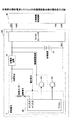
図1には、燃料電池3の一般的な構成例を示す。燃料電池3は、燃料電池本体5、燃料電池制御部52およびその他の補機で構成される。その他の補機には、燃料タンク17、燃料ポンプP1、混合タンク19、燃料供給路27、循環ポンプP2、ブロワーP3、凝縮器31、冷却風37、ファン35、水タンク20および水ポンプP4等が含まれる。
FIG. 1 shows a general configuration example of the
燃料電池制御部52は、燃料電池3の全体制御を行う。また燃料電池本体5は、メタノールを電気化学的酸化する触媒(メタノール酸化電極触媒)を有するアノード(燃料極)7と酸素を選択的に電気化学的還元する触媒(酸素還元電極触媒)を有するカソード(空気極)9との間に電解質膜11を有する。燃料電池本体5は単セルとしても良いが、通常は必要な電圧を確保するため、単セルを直列接続したスタックが用いられる。
The fuel
補機のうち、メタノールを貯蔵する燃料タンク17は、燃料ポンプP1を介して混合タンク19に接続されており、燃料ポンプP1の動作時に燃料タンク17内のメタノールは、混合タンク19に輸送される。
Among the auxiliary machines, the fuel tank 17 for storing methanol is connected to the
混合タンク19には、燃料ポンプP1によって燃料タンク17から供給されたメタノールと、燃料電池本体5から回収された水との混合液が入っている。混合タンク19と燃料電池本体5とをつなぐ燃料供給路27には循環ポンプP2が配置されており、このポンプは、混合タンク19内のメタノール水溶液を燃料電池本体5のアノード側に供給する。またブロワーP3によって、燃料電池本体5のカソード側に空気が供給される。
The mixing
メタノール水溶液と空気の供給された燃料電池本体5では、アノード7とカソード9との間に電力が生じるとともに、アノード側には二酸化炭素が発生し、カソード側には水が発生する。アノード側からの排気は、混合タンク19で回収される。また燃料電池内部温度が高いため、カソード側で発生した水は、一部水蒸気になっているが、凝集器31を通過する際に冷却され、水と空気に分離されて水タンク20に戻される。尚、凝集器31はファン35で作られた冷却風37で冷却される。水タンク20で回収された水は、燃料タンク17から混合タンク19へ供給されたメタノールを希釈するために用いられ、その他不要な水は水蒸気として、二酸化炭素とともに混合タンク19から排出される。
In the fuel cell
混合タンク19内のメタノール水溶液の量が少なくなると、水ポンプP4が間欠動作して、水を水タンク20から混合タンク19に供給する。また発電によりメタノールが消費され濃度が薄くなると、燃料ポンプP1が間欠動作して、高濃度のメタノールが混合タンク19内に供給される。
When the amount of aqueous methanol solution in the
通常は、混合タンク19内のメタノール濃度を測定するため、メタノール濃度センサーが利用される。
Normally, a methanol concentration sensor is used to measure the methanol concentration in the
これに対して本発明では、混合タンク19内のメタノール濃度制御を高額なメタノール濃度センサーを利用せずに行うことができることに特徴がある。
In contrast, the present invention is characterized in that the methanol concentration in the
以下本発明の特徴について説明する。 The features of the present invention will be described below.
本発明は、温度や負荷等の燃料電池出力特性に影響を及ぼす因子が一定の場合、燃料電池の出力電圧または出力電流(以下、これらをまとめて「燃料電池出力」ともいう)からアルコール濃度を予測することができることに着目したものである。すなわち本発明の燃料電池では、燃料電池出力および温度から、燃料中のアルコール濃度を算定し、この結果に基づいて、燃料ポンプP1および/または水ポンプP4を作動させ、混合タンク19のアルコール濃度を制御する。
In the present invention, when factors affecting fuel cell output characteristics such as temperature and load are constant, the alcohol concentration is determined from the output voltage or output current of the fuel cell (hereinafter collectively referred to as “fuel cell output”). It focuses on the fact that it can be predicted. That is, in the fuel cell of the present invention, the alcohol concentration in the fuel is calculated from the fuel cell output and temperature, and based on this result, the fuel pump P1 and / or the water pump P4 is operated, and the alcohol concentration in the
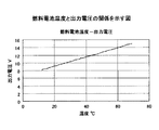
図2には、各温度でのアルコール濃度と燃料電池出力電圧の関係を、また図3には、燃料電池温度と出力電圧の関係を示す。この図より温度と出力電圧から、アルコール濃度を算定することができる。例えば、温度が60℃で出力電圧が14Vの場合、アルコール濃度は3%と推定できる。従って、タンク内のアルコール濃度を例えば3%に維持したい場合、温度一定の条件下で、出力電圧が14Vとなるように、燃料電池制御部52によって、図1の燃料ポンプP1および/または水ポンプP4を作動させて、燃料タンクからアルコールを補給する。さらに図4には、アルコール濃度と燃料電池出力電流との関係を示す。両者の間にも同様の関係が成立し、温度と出力電流から、アルコール濃度を算定することが可能となる。
FIG. 2 shows the relationship between alcohol concentration and fuel cell output voltage at each temperature, and FIG. 3 shows the relationship between fuel cell temperature and output voltage. From this figure, the alcohol concentration can be calculated from the temperature and the output voltage. For example, when the temperature is 60 ° C. and the output voltage is 14 V, the alcohol concentration can be estimated to be 3%. Therefore, when it is desired to maintain the alcohol concentration in the tank at, for example, 3%, the fuel
このように、本発明の燃料電池システムでは、アルコール濃度センサーを設置しなくても、燃料電池出力と温度の関係からアルコール濃度の算定を行うことができる。 Thus, in the fuel cell system of the present invention, the alcohol concentration can be calculated from the relationship between the fuel cell output and the temperature without installing an alcohol concentration sensor.
ここで、燃料電池を電子機器等の駆動源として使用することを考慮すると、電子機器の種類によっては、燃料電池出力から正確なアルコール濃度を把握することができない場合が想定される。例えば電子写真方式の画像形成装置では、定着ローラにおける熱定着時に瞬間的に大電力を消費する。またインクジェット方式の画像形成装置では、キャリッジの移動開始時、あるいは記録媒体の送り開始時に、電流が急激に増大する。このような場合には、燃料電池側の出力が変動してしまい、メタノール濃度を正確に求めることが難しくなる可能性がある。 Here, considering that the fuel cell is used as a drive source for an electronic device or the like, depending on the type of the electronic device, it may be assumed that an accurate alcohol concentration cannot be obtained from the fuel cell output. For example, in an electrophotographic image forming apparatus, a large amount of power is instantaneously consumed when heat is fixed on a fixing roller. In an ink jet image forming apparatus, the current increases rapidly when the carriage starts moving or when the recording medium starts to be fed. In such a case, the output on the fuel cell side fluctuates, which may make it difficult to accurately determine the methanol concentration.
しかし本発明では以下に示すように、燃料電池によって駆動される電子機器等の電力消費量が大きく変動する場合であっても、燃料電池出力を一定に保持し、アルコール濃度を正確に算定することができる。 However, in the present invention, as shown below, even when the power consumption of an electronic device or the like driven by a fuel cell fluctuates greatly, the fuel cell output is kept constant and the alcohol concentration is accurately calculated. Can do.
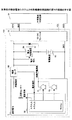
図5には、負荷変動の激しい電子機器用の電源として利用した際にも、燃料電池出力を一定に保持する燃料電池システムの構成を示す。燃料電池システムには、温度センサーと定電流装置54が設けられる。温度センサーは、燃料電池本体3に取り付けられ、温度センサーからの温度信号は、燃料電池制御部52のA/D入力端子に入力される。燃料電池の出力電流は、定電流装置54を経由し取り出されるため、電子機器側で消費する電流が著しく変化しても、燃料電池出力電流はこの影響を受けず、結果的に出力電圧は、スタックの温度とアルコール濃度で決まる一定値となる。従って前述の方法で、混合タンク19のアルコール濃度を制御することが可能となる。
FIG. 5 shows the configuration of a fuel cell system that keeps the fuel cell output constant even when it is used as a power source for electronic equipment with a heavy load fluctuation. The fuel cell system is provided with a temperature sensor and a constant
このように本発明の燃料電池システムでは、駆動される電子機器等の種類によらず、燃料電池出力を一定に保持し、アルコール濃度を正確に算定することができる。 Thus, in the fuel cell system of the present invention, the fuel cell output can be kept constant and the alcohol concentration can be accurately calculated regardless of the type of electronic equipment to be driven.
従って、アルコール濃度センサーを設置しなくても、燃料電池システムからの安定な電力供給が可能となる。従って燃料電池システムを小型、軽量化することが可能となり、低コスト化も可能となる。 Therefore, stable power supply from the fuel cell system is possible without installing an alcohol concentration sensor. Therefore, the fuel cell system can be reduced in size and weight, and the cost can be reduced.
以下、上述の特徴的効果を発揮させることのできる燃料電池システムの実施例について説明する。
(第1の実施例)
図6には、燃料電池システム100の第1の例を示す。燃料電池システム100は外部機器の制御回路50と接続される。また両者の間には、定電流装置54と、蓄電装置53と、DC-DCコンバータ51とが設けられる。定電流装置54は、燃料電池3の出力側から見て最上流側に設置され、DC-DCコンバータ51はその下流側に定電流装置54と直列に設置される。蓄電装置53は、その出力電流が定電流装置54側からの電流と合流して、DC-DCコンバータ51の方に供給されるよう、燃料電池3と並列に設置される。ただし、定電流装置54側からの出力電流が蓄電装置53の方向に流れる場合もある(充電時)。定電流装置54は、燃料電池3からの出力電流を一定に維持する役割を果たす。例えば外部機器が電子機器であって、その制御回路50に大電流が必要となった場合には、蓄電装置53から必要分の電流が供給される。このように定電流装置54によって、燃料電池は外部機器側の大きな消費電力変動の影響を受けることはない。従って、燃料電池3の出力電圧は一定に維持され、この電圧値と測定温度から上述の手法により、混合タンク19のアルコール濃度を算出することが可能となる。そして得られた算定値に基づいて燃料電池制御部52によって、燃料ポンプP1および/または水ポンプP4が作動され、燃料タンク内のアルコール濃度は一定に維持されるため、燃料電池3を常時安定な出力で稼動させることが可能となる。
Hereinafter, embodiments of the fuel cell system capable of exhibiting the above-described characteristic effects will be described.
(First embodiment)
FIG. 6 shows a first example of the
ただし、アルコール濃度を変えた場合、その変化が出力電圧や出力電流の変化として現れるまでに時間を要するので、出力電圧や出力電流が変化するまで補給を行うと、補給量がオーバーしてしまうので、例えば1分毎にアルコール濃度を算出し、少ないときは1ccのアルコールを補給する等の工夫が必要である。
(第2の実施例)
第2の実施例を図7に示す。第1の実施例では、燃料電池3の出力電流を一定に維持するため、定電流装置54が用いられる。一方この実施例では、燃料電池3の出力側から見て最上流側に設置される電流センサー55、蓄電装置53および蓄電装置53と直列に設置された電流制御装置56によって、同様の効果が発揮される。ここで電流センサー55と蓄電装置53の位置関係は、第1の実施例における定電流装置54と、蓄電装置53との位置関係と同様である。具体的には、電流センサー55は、燃料電池3からの出力電流信号を電流制御装置56に伝送する。電流制御装置56は、この出力電流信号に基づいて、蓄電装置53への充電電流を制御し、これにより燃料電池3の出力電流が一定に維持される。従って第1の実施例の場合と同様に、燃料電池3の出力電圧と測定温度から混合タンク19のアルコール濃度を算出することが可能となる。
(第3の実施例)
第3の実施例を図8に示す。この実施例の基本構造は第2の実施例と同様であるが、電流制御装置56と並列にダイオード57が設置される。この配置では、ダイオード57によって、蓄電装置53からの電流を電流制御装置56からバイパスさせることが可能であり、電圧制御回路56による電流の抵抗ロスを低減させることができる。
(第4の実施例)
第4の実施例を図9に示す。第4の実施例の構成素子およびそれらの配置は、第2の実施例と同様である。しかしこの例では、電流制御装置56は、燃料電池の出力を電圧信号として利用し、出力電圧が一定となるように、蓄電装置53の充電電流を制御する。これにより、燃料電池3の出力電圧は一定に維持され、電流センサー55からの電流信号と測定温度の関係から、混合タンク19のアルコール濃度を算出することが可能となる。
(第5の実施例)
第5の実施例を図10に示す。この実施例は、第4の実施例において、電流制御装置56と並列にダイオード57が設置される。これにより、蓄電装置53からの電流を電流制御装置56からバイパスさせ、電流制御装置56による電流の抵抗ロスを低減させることができる。
(第6および第7の実施例)
燃料電池制御部52からの制御信号によって、定電流装置54の動作を直接制御しても良い。例えば、通常、定電流装置54内では電流のオンオフが繰り返されるが、アルコール濃度算定時以外のときは、定電流装置54にこのような動作をさせずに、通電を常時継続させる。この場合も、定電流装置54で生じる電力ロスを有意に抑制することができる。
However, if the alcohol concentration is changed, it takes time for the change to appear as a change in the output voltage or output current.If replenishment is performed until the output voltage or output current changes, the replenishment amount will be exceeded. For example, it is necessary to devise such as calculating the alcohol concentration every minute and supplying 1 cc of alcohol when the alcohol concentration is low.
(Second embodiment)
A second embodiment is shown in FIG. In the first embodiment, a constant
(Third embodiment)
A third embodiment is shown in FIG. The basic structure of this embodiment is the same as that of the second embodiment, but a
(Fourth embodiment)
A fourth embodiment is shown in FIG. The components of the fourth embodiment and their arrangement are the same as those of the second embodiment. However, in this example, the
(Fifth embodiment)
A fifth embodiment is shown in FIG. In this embodiment, a
(Sixth and seventh embodiments)
The operation of the constant
第6の実施例を図11に、第7の実施例を図12に示す。第6の実施例は、図8の第3の実施例において、電流制御装置56を一定期間だけ動作させる方式のものである。また第7の実施例は、図10の第5の実施例において、電流制御装置56を一定期間だけ動作させる方式のものである。すなわち、アルコール濃度算定時以外のときは、燃料電池制御部から制御解除信号が出力され、その間は電流制御装置56はショートされる。これにより、電流制御装置56で生じる電力ロスを有意に抑制することができる。
(第8の実施例)
第8の実施例を図13に示す。この実施例は、第1の実施例とほぼ同様の構成となっている。ただし、本実施例では、定電流装置54と並列にスイッチ60が設けられる。従って、定電流装置54を流れる電流は、必要に応じて、燃料電池制御部からの切替信号によってバイパスさせることができる。例えば、アルコール濃度算定時以外のときは、燃料電池制御部52から切替信号が出力され、その間は定電流装置54はバイパスされる。これにより、定電流装置54で生じる電力ロスを有意に抑制することができる。
A sixth embodiment is shown in FIG. 11, and a seventh embodiment is shown in FIG. The sixth embodiment is a system in which the
(Eighth embodiment)
An eighth embodiment is shown in FIG. This embodiment has almost the same configuration as the first embodiment. However, in this embodiment, a
なお本発明は、以上の実施例に限定されるものではなく、本発明では、燃料電池側の出力が一定となるシステムであれば、電子機器との間はいかなる素子で構成としても良いことに留意する必要がある。 The present invention is not limited to the above-described embodiments. In the present invention, any element may be used between the electronic device and the electronic device as long as the output on the fuel cell side is constant. It is necessary to keep in mind.
以下このような燃料電池システムを備える電子機器の一態様を説明する。 Hereinafter, an aspect of an electronic apparatus including such a fuel cell system will be described.
図14は、本発明の燃料電池システムを電源とするインクジェットプリンターの概観斜視図である。このインクジェットプリンターは、燃料電池システムと、その燃料電池システムから電力の供給をうけて動作するプリンター部分で構成される。 FIG. 14 is a schematic perspective view of an ink jet printer using the fuel cell system of the present invention as a power source. This ink jet printer is composed of a fuel cell system and a printer portion that operates by receiving power from the fuel cell system.
次に、図15を用いてプリンター部分の内部構造を説明する。図15には、ラインフィードモータ201と、押さえ部材202と、ワイヤ203と、HP(ポジション)センサー204と、記録ヘッドカートリッジ205と、キャリッジ206と、ケーブル207と、キャリッジモータ208と、記録用紙209と、プラテンローラ210と、シャフト211とが示されている。
Next, the internal structure of the printer portion will be described with reference to FIG. In FIG. 15, a
記録ヘッドカートリッジ205は、記録ヘッドIJHとインク供給源たるインクタンクとを一体としたものである。この記録ヘッドカートリッジ205は、押さえ部材202によりキャリッジ206の上に固定されており、これらはシャフト211にそって長手方向に往復運動可能となっている。
The
記録ヘッドIJHより吐出されたインク滴は、記録ヘッドIJHと微小間隔をおいて、プラテンローラ210に記録面を規制された記録用紙209に到達し、画像を形成する。記録ヘッドIJHにはケーブル207及びこれに結合する端子を介して適宜のデータ供給源より画像データに応じた記録タイミングパルスが供給される。
The ink droplets ejected from the recording head IJH reach the
記録ヘッドカートリッジ205は、用いるインク色等に応じて、1ないし複数個(図示例では2個)を設けることができる。キャリッジモータ208はキャリッジ206をシャフト211に沿って走査させるためのものである。ワイヤ203はモータ208の駆動力をキャリッジ206に伝達するためのものである。また、ラインフィードモータ201はプラテンローラ210に結合して記録用紙209を搬送させるためのものである。HPセンサー204はキャリッジ206の位置を検出するものである。
One to a plurality of recording head cartridges 205 (two in the illustrated example) can be provided depending on the ink color used. The
次に図16を用いて、本実施の形態のインクジェットプリンターの記録制御を実行するためのプリンター制御回路50と燃料電池システム100について説明する。
Next, the
図16に示される燃料電池システム100は、インクジェットプリンターの記録動作を行うのに必要な電力を供給するもので、燃料電池とDC−DCコンバータからなるものである。また、制御手段に対応する制御回路50は、CPU101と、ROM102と、RAM103と、データ受信部104と、DMA/RAMコントローラ105と、不揮発性メモリ106と、ヘッドドライバ107と、ヘッドコントローラ108と、タイミング制御部112と、ラインフィードドライバ113と、インク流量検出部114と、ラインフィードモータ201と、キャリッジモータ208と、記録ヘッドIJHとで構成される。
A
CPU101は、このインクジェットプリンターの動作制御及びデータ処理を実行するためのものである。ROM102はCPU101の制御プログラムやフォント処理のための各種データを格納するものである。RAM103は受信した画像データを含め各種データを一時格納するものである。データ受信部104はホストコンピュータ等の外部機器から送られてくる画像データを取り込むためのものである。
The
DMA/RAMコントローラ105はデータ受信部104で受信した画像データをRAM103へDMA転送したり、CPU101からRAM103へのアクセスを制御するものである。また不揮発性メモリ106はプリンター固有のパラメータを格納するものであり、例えばEEPROM等が挙げられる。ヘッドドライバ107は記録ヘッドIJHを駆動するものである。ヘッドコントローラ108はCPU101からの制御によりヘッドドライバ107への画像データの転送とヒートパルス信号を発生するものである。
The DMA /
キャリッジモータドライバ110とキャリッジモータ208及びタイミング制御部112は、CPU101から供給される制御信号とエンコーダ等による記録タイミングパルスによって記録ヘッドIJHの移動を行う制御系である。この記録ヘッドIJHが移動する方向は主走査方向と呼ばれる。ラインフィードモータドライバ113とラインフィードモータ201は、CPU101から供給される制御信号によって記録用紙209等の記録媒体の搬送を行う制御系である。この記録媒体が搬送される方向は副走査方向と呼ばれる。
The
インク流量検出部114は、記録ヘッドIJHに送られた記録信号から、所定時間内において記録のために吐出されたインク滴(ドット)の数をカウントし、インクタンクから記録ヘッドIJHに供給されるインクの流量を検出する制御回路である。
The ink flow
以上説明した図16を用いて本実施形態のインクジェットプリンターが実行する基本的な記録制御について説明する。 The basic recording control executed by the ink jet printer according to the present embodiment will be described with reference to FIG. 16 described above.
まず、データ受信部104によってホストコンピュータより入力された画像データは、DMA/RAMコントローラ105を介してRAM103に一時格納される。CPU101は、ROM102に格納された制御プログラムを実行して受信コマンド、画像データ、文字コードの解析を行う。その後、入力された画像データは、CPU101により記録データに変換され、順次、RAM103に格納される。受信コマンドには記録制御情報が含まれ、この記録制御情報に応じた記録パス数により記録が行われる。
First, image data input from the host computer by the
1ライン分の記録データの展開が終了するか、もしくは、受信コマンドの一つである記録命令をホストコンピュータから入力された時点で、キャリッジモータドライバ110によりキャリッジモータ208が駆動される。そして、タイミング制御部112から出力される記録タイミングパルスに同期して、RAM103に格納されている記録データがDMA/RAMコントローラ105及びヘッドコントローラ108を介してヘッドドライバ107に転送される。そして、ヘッドコントローラ108からヒートパルス信号がヘッドドライバ107に送られて記録ヘッドIJHからインク滴が吐出される。
The
1ライン分の記録が終了するとラインフィードモータ201が駆動されて改行が行われ、1連の手順が終了する。このような手順が記録用紙209の1ページに渡って繰り返して行われることにより、1ページ分の記録動作が完了する。
When the recording for one line is completed, the
以上のような制御により、発生し得る吐出量を越えない限りは、少ない走査回数の記録モードで記録を行うこととなり、実質的な記録速度が速くなるという効果がある。 As long as the discharge amount that can be generated is not exceeded by the above control, printing is performed in a printing mode with a small number of scans, and there is an effect that a substantial printing speed is increased.
なお、上記の例では、電子機器としてインクジェットプリンターを用いて説明したが、電子機器は、電子写真方式の画像形成装置やその他の電子機器であっても良い。 In the above example, an inkjet printer is used as the electronic device. However, the electronic device may be an electrophotographic image forming apparatus or other electronic device.
以上説明したように、本発明では、燃料電池本体の出力電圧または出力電流と温度から燃料アルコール濃度を予測する。従って本発明による燃料電池システムは、高価なアルコール濃度センサーを設置しなくても、安定な出力を行うことが可能となる。また燃料電池側からの出力が一定となるようにシステムを構成したため、本燃料電池システムは、プリンター等のような、負荷変動の激しい機器の電力供給源(電源ユニット)に使用しても、同様に安定な出力が可能となる。従って燃料電池システムを小型、軽量化することが可能となり、さらに低コスト化も可能となる。 As described above, in the present invention, the fuel alcohol concentration is predicted from the output voltage or output current of the fuel cell main body and the temperature. Therefore, the fuel cell system according to the present invention can perform stable output without installing an expensive alcohol concentration sensor. In addition, since the system is configured so that the output from the fuel cell side is constant, this fuel cell system is the same even if it is used as a power supply source (power supply unit) for a device with a heavy load fluctuation such as a printer. Stable output is possible. Accordingly, the fuel cell system can be reduced in size and weight, and the cost can be further reduced.
本発明は、アルコールを燃料とする燃料電池を有する電子機器全般に利用できる。 The present invention can be used for all electronic devices having a fuel cell using alcohol as a fuel.
3 燃料電池
5 燃料電池本体
7 アノード
9 カソード
17 燃料タンク
19 混合タンク
20 水タンク
27 燃料供給路
31 凝縮器
35 ファン
37 冷却風
50 電子機器制御回路
51 DC−DCコンバータ
52 燃料電池制御部
53 蓄電装置
54 定電流装置
56 電流制御装置
57 ダイオード
60 スイッチ
100 燃料電池システム
101 CPU
102 ROM
103 RAM
104 データ受信部
105 RAM/DMAコントローラ
106 不揮発性メモリ
107 ヘッドドライバ
108 ヘッドコントローラ
110 キャリッジモータドライバ
112 タイミング制御部
113 ラインフィードドライバ
114 インク流量検出部
IJH 記録ヘッド
P1 燃料ポンプ
P2 循環ポンプ
P3 ブロワー
P4 水ポンプ。
DESCRIPTION OF
102 ROM
103 RAM
104
Claims (14)
前記制御手段は、燃料電池本体の温度および出力電圧または出力電流に基づいて、前記燃料ポンプの動作を制御することを特徴とする燃料電池システム。 A fuel cell main body, a storage tank for alcohol as a fuel source, a mixing tank connected to the storage tank via a fuel pump and supplying fuel containing alcohol and water to the fuel cell main body, and operation of the fuel pump A fuel cell system having control means for controlling the fuel cell output by controlling
The control means controls the operation of the fuel pump based on the temperature of the fuel cell main body and the output voltage or output current.
当該燃料電池システムは、前記外部機器の負荷変動によらず、燃料電池本体からの出力電流を一定に維持する回路手段を有し、
前記制御手段は、燃料電池本体の温度および出力電圧に基づいて、前記燃料ポンプの動作を制御することを特徴とする燃料電池システム。 A fuel cell main body, a storage tank for alcohol as a fuel source, a mixing tank connected to the storage tank via a fuel pump and supplying fuel containing alcohol and water to the fuel cell main body, and operation of the fuel pump A fuel cell system for controlling the fuel cell output and controlling the fuel cell output, connected to a control circuit of an external device, and driving the external device,
The fuel cell system has circuit means for maintaining a constant output current from the fuel cell body regardless of load fluctuations of the external device,
The control means controls the operation of the fuel pump based on the temperature and output voltage of the fuel cell main body.
当該燃料電池システムは、前記外部機器の負荷変動によらず、燃料電池本体からの出力電圧を一定に維持する回路手段を有し、
前記制御手段は、燃料電池本体の温度および出力電流に基づいて、前記燃料ポンプの動作を制御することを特徴とする燃料電池システム。 A fuel cell main body, a storage tank for alcohol as a fuel source, a mixing tank connected to the storage tank via a fuel pump and supplying fuel containing alcohol and water to the fuel cell main body, and operation of the fuel pump A fuel cell system for controlling the fuel cell output and controlling the fuel cell output, connected to a control circuit of an external device, and driving the external device,
The fuel cell system has circuit means for maintaining a constant output voltage from the fuel cell body regardless of load fluctuations of the external device,
The control means controls the operation of the fuel pump based on the temperature and output current of the fuel cell main body.
Priority Applications (1)
| Application Number | Priority Date | Filing Date | Title |
|---|---|---|---|
| JP2005102853A JP2006286321A (en) | 2005-03-31 | 2005-03-31 | Fuel cell system, electronic apparatus equipped with the same, and image formation device |
Applications Claiming Priority (1)
| Application Number | Priority Date | Filing Date | Title |
|---|---|---|---|
| JP2005102853A JP2006286321A (en) | 2005-03-31 | 2005-03-31 | Fuel cell system, electronic apparatus equipped with the same, and image formation device |
Publications (2)
| Publication Number | Publication Date |
|---|---|
| JP2006286321A true JP2006286321A (en) | 2006-10-19 |
| JP2006286321A5 JP2006286321A5 (en) | 2008-05-08 |
Family
ID=37408023
Family Applications (1)
| Application Number | Title | Priority Date | Filing Date |
|---|---|---|---|
| JP2005102853A Pending JP2006286321A (en) | 2005-03-31 | 2005-03-31 | Fuel cell system, electronic apparatus equipped with the same, and image formation device |
Country Status (1)
| Country | Link |
|---|---|
| JP (1) | JP2006286321A (en) |
Cited By (14)
| Publication number | Priority date | Publication date | Assignee | Title |
|---|---|---|---|---|
| KR100786481B1 (en) | 2006-05-11 | 2007-12-17 | 삼성에스디아이 주식회사 | Method and Apparatus for Controlling Operation of Direct Methanol Fuel Cell System |
| KR100811982B1 (en) | 2007-01-17 | 2008-03-10 | 삼성에스디아이 주식회사 | Fuel cell system and control method of it |
| JP2008159482A (en) * | 2006-12-25 | 2008-07-10 | Ricoh Co Ltd | Fuel cell unit, electronic apparatus and image formation device |
| JP2008192430A (en) * | 2007-02-02 | 2008-08-21 | Ricoh Co Ltd | Fuel cell unit, electronic equipment, and image forming device |
| JP2009123383A (en) * | 2007-11-12 | 2009-06-04 | Hitachi Ltd | Fuel cell power supply system, and its operation method |
| WO2010021231A1 (en) * | 2008-08-18 | 2010-02-25 | ソニー株式会社 | Fuel cell system and electronic device |
| US7785745B2 (en) | 2007-11-30 | 2010-08-31 | Kabushiki Kaisha Toshiba | Fuel cell apparatus |
| JP2010225460A (en) * | 2009-03-24 | 2010-10-07 | Toshiba Corp | Fuel cell system |
| US7846609B2 (en) | 2006-11-30 | 2010-12-07 | Samsung Sdi Co., Ltd. | Module-type fuel cell system |
| JP2011054285A (en) * | 2009-08-31 | 2011-03-17 | Hitachi Ltd | Fuel cell using organic fuel |
| US7935448B2 (en) | 2006-05-11 | 2011-05-03 | Samsung Sdi Co., Ltd. | Method and apparatus for controlling operation of direct methanol fuel cell system |
| US8227118B2 (en) | 2007-08-29 | 2012-07-24 | Kabushiki Kaisha Toshiba | Method of driving fuel cell device |
| JP2014049341A (en) * | 2012-08-31 | 2014-03-17 | Daihatsu Motor Co Ltd | Fuel concentration control device |
| KR101822281B1 (en) * | 2016-05-04 | 2018-01-25 | 현대자동차주식회사 | Fuel cell system and controlling method therefor |
Citations (6)
| Publication number | Priority date | Publication date | Assignee | Title |
|---|---|---|---|---|
| JPH08214453A (en) * | 1995-02-01 | 1996-08-20 | Mazda Motor Corp | Hybrid power supply controlling system |
| JP2001210345A (en) * | 2000-01-24 | 2001-08-03 | Nissan Motor Co Ltd | Output control device of fuel cell system |
| JP2004071261A (en) * | 2002-08-02 | 2004-03-04 | Toshiba Corp | Fuel cell device |
| JP2004234869A (en) * | 2003-01-28 | 2004-08-19 | Hitachi Ltd | Fuel cell system |
| WO2005008822A1 (en) * | 2003-07-16 | 2005-01-27 | Kabushiki Kaisha Toshiba | Liquid type fuel cell system and boosting unit thereof |
| JP2005025959A (en) * | 2003-06-30 | 2005-01-27 | Matsushita Electric Ind Co Ltd | Method and system for operating fuel cell |
-
2005
- 2005-03-31 JP JP2005102853A patent/JP2006286321A/en active Pending
Patent Citations (6)
| Publication number | Priority date | Publication date | Assignee | Title |
|---|---|---|---|---|
| JPH08214453A (en) * | 1995-02-01 | 1996-08-20 | Mazda Motor Corp | Hybrid power supply controlling system |
| JP2001210345A (en) * | 2000-01-24 | 2001-08-03 | Nissan Motor Co Ltd | Output control device of fuel cell system |
| JP2004071261A (en) * | 2002-08-02 | 2004-03-04 | Toshiba Corp | Fuel cell device |
| JP2004234869A (en) * | 2003-01-28 | 2004-08-19 | Hitachi Ltd | Fuel cell system |
| JP2005025959A (en) * | 2003-06-30 | 2005-01-27 | Matsushita Electric Ind Co Ltd | Method and system for operating fuel cell |
| WO2005008822A1 (en) * | 2003-07-16 | 2005-01-27 | Kabushiki Kaisha Toshiba | Liquid type fuel cell system and boosting unit thereof |
Cited By (16)
| Publication number | Priority date | Publication date | Assignee | Title |
|---|---|---|---|---|
| KR100786481B1 (en) | 2006-05-11 | 2007-12-17 | 삼성에스디아이 주식회사 | Method and Apparatus for Controlling Operation of Direct Methanol Fuel Cell System |
| US7935448B2 (en) | 2006-05-11 | 2011-05-03 | Samsung Sdi Co., Ltd. | Method and apparatus for controlling operation of direct methanol fuel cell system |
| US7846609B2 (en) | 2006-11-30 | 2010-12-07 | Samsung Sdi Co., Ltd. | Module-type fuel cell system |
| JP2008159482A (en) * | 2006-12-25 | 2008-07-10 | Ricoh Co Ltd | Fuel cell unit, electronic apparatus and image formation device |
| US8343674B2 (en) | 2007-01-17 | 2013-01-01 | Samsung Sdi Co., Ltd. | Fuel cell system and control method of the same |
| KR100811982B1 (en) | 2007-01-17 | 2008-03-10 | 삼성에스디아이 주식회사 | Fuel cell system and control method of it |
| JP2008192430A (en) * | 2007-02-02 | 2008-08-21 | Ricoh Co Ltd | Fuel cell unit, electronic equipment, and image forming device |
| US8227118B2 (en) | 2007-08-29 | 2012-07-24 | Kabushiki Kaisha Toshiba | Method of driving fuel cell device |
| JP2009123383A (en) * | 2007-11-12 | 2009-06-04 | Hitachi Ltd | Fuel cell power supply system, and its operation method |
| US7785745B2 (en) | 2007-11-30 | 2010-08-31 | Kabushiki Kaisha Toshiba | Fuel cell apparatus |
| WO2010021231A1 (en) * | 2008-08-18 | 2010-02-25 | ソニー株式会社 | Fuel cell system and electronic device |
| US8846257B2 (en) | 2008-08-18 | 2014-09-30 | Sony Corporation | Fuel cell system and electronic device |
| JP2010225460A (en) * | 2009-03-24 | 2010-10-07 | Toshiba Corp | Fuel cell system |
| JP2011054285A (en) * | 2009-08-31 | 2011-03-17 | Hitachi Ltd | Fuel cell using organic fuel |
| JP2014049341A (en) * | 2012-08-31 | 2014-03-17 | Daihatsu Motor Co Ltd | Fuel concentration control device |
| KR101822281B1 (en) * | 2016-05-04 | 2018-01-25 | 현대자동차주식회사 | Fuel cell system and controlling method therefor |
Similar Documents
| Publication | Publication Date | Title |
|---|---|---|
| JP2006286321A (en) | Fuel cell system, electronic apparatus equipped with the same, and image formation device | |
| US7871147B2 (en) | Image forming apparatus and method for humidifying in head cap | |
| US20070085521A1 (en) | Power supply for switching operation, electronic apparatus including the same, and method of controlling the same | |
| EP3340595B1 (en) | Printing apparatus and power supply unit for printing apparatus | |
| JP2008084688A (en) | Fuel cell system and control method for fuel cell system | |
| JP4472542B2 (en) | Image forming apparatus | |
| JP2007245355A (en) | Printer, supply current controller and computer program | |
| JP2012125928A (en) | Recording apparatus and power apparatus | |
| US8845048B2 (en) | Liquid ejecting device, storage medium, and method of controlling liquid ejecting device | |
| US8803932B2 (en) | Printer | |
| JP2008146950A (en) | Fuel cell system, electronic device, and image forming device | |
| JP4515235B2 (en) | Electronic device, fuel cell control method | |
| JP2008213358A (en) | Inkjet image-forming device and method of cleaning and retaining moisture in head cap of inkjet image-forming device | |
| JP2006166577A (en) | Power supply control method and power unit | |
| JP2005331462A (en) | Method and detector for detecting voltage reduction in line printer | |
| JP2006166576A (en) | Power system and image forming apparatus | |
| US8757759B2 (en) | Temperature detecting apparatus | |
| JP2006236610A (en) | Power source system, electronic equipment, and image forming device | |
| JP2006210176A (en) | Power supply device, and electron/electric equipment and image forming apparatus using device | |
| US20080117244A1 (en) | Apparatus and method for thermal printers that employ a battery or other portable power source | |
| JP2008243398A (en) | Fuel cell system, electronic device, and image forming device | |
| JP2006260996A (en) | Fuel dell system and image forming device driven by the same | |
| JP2011210637A (en) | Fuel cell system | |
| JP2009093949A (en) | Fuel cell system and electronic device | |
| JPH06344638A (en) | Recorder and power demand control method in the recorder |
Legal Events
| Date | Code | Title | Description |
|---|---|---|---|
| A521 | Written amendment |
Free format text: JAPANESE INTERMEDIATE CODE: A523 Effective date: 20080326 |
|
| A621 | Written request for application examination |
Free format text: JAPANESE INTERMEDIATE CODE: A621 Effective date: 20080326 |
|
| A977 | Report on retrieval |
Free format text: JAPANESE INTERMEDIATE CODE: A971007 Effective date: 20110818 |
|
| A131 | Notification of reasons for refusal |
Free format text: JAPANESE INTERMEDIATE CODE: A131 Effective date: 20110823 |
|
| A521 | Written amendment |
Free format text: JAPANESE INTERMEDIATE CODE: A523 Effective date: 20110909 |
|
| A131 | Notification of reasons for refusal |
Free format text: JAPANESE INTERMEDIATE CODE: A131 Effective date: 20120117 |
|
| A02 | Decision of refusal |
Free format text: JAPANESE INTERMEDIATE CODE: A02 Effective date: 20120814 |