JP3843173B2 - Pinless folding machine - Google Patents
Pinless folding machine Download PDFInfo
- Publication number
- JP3843173B2 JP3843173B2 JP27680897A JP27680897A JP3843173B2 JP 3843173 B2 JP3843173 B2 JP 3843173B2 JP 27680897 A JP27680897 A JP 27680897A JP 27680897 A JP27680897 A JP 27680897A JP 3843173 B2 JP3843173 B2 JP 3843173B2
- Authority
- JP
- Japan
- Prior art keywords
- paper
- cylinder
- web
- pressing
- cutting
- Prior art date
- Legal status (The legal status is an assumption and is not a legal conclusion. Google has not performed a legal analysis and makes no representation as to the accuracy of the status listed.)
- Expired - Fee Related
Links
Images


Description
【0001】
【発明の属する技術分野】
本発明は、輪転印刷機のピンレス折機に関する。
【0002】
【従来の技術】
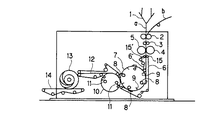
輪転印刷機用ピンレス折機として例えば、図6及び図7に示すようなものが知られている。これを説明すると、図6の1が三角板で、同三角板1により2つに折られたウェブa(又は折られないウェブb)を、ウェブaの走行速度と同じ周速度で回転している一対の第1ニッピングローラ2の間と一対の第2ニッピングローラ3の間とを経てカッタ胴4とカッタ受け胴5とよりなる断裁装置へ送って、切断する。
【0003】
この切断されたウェブaを、一対のガイドローラ15,15’により案内している一対の増速搬送ベルト6,6’により急速に増速して、先行紙の紙尻と後続紙の先端18との間を開き、互いの間に隙間Sを形成して(図7参照)、後続紙の先端18を先行紙の紙尻で干渉させることなく、折胴7の爪8によりくわえる。
【0004】
そして、くわえた後続紙の中央部分を、増速搬送ベルト6,6’と同周速に増速にしている折胴7の折ブレード9によりくわえ胴10のくわえ装置11のくわえ板とくわえ座との間へ押し込んで、2つ折りにした後、搬送ベルト12→排紙羽根車13→排紙コンベア14を経て折機外へ搬出する。
【0005】
ところが、このようなピンレス折機には、次のような問題があった。即ち、
▲1▼ ウェブaを断裁した後、ウェブaをウェブaの走行速度よりも急速に増速させる(15〜40%程度増速させる)ので、紙端折れ、特に増速搬送ベルト6,6’よりはみ出している紙の両端部に紙端折れが生じやすい。また、紙が傾斜し易くて、折精度不良等の障害が発生しやすい。
▲2▼ 増速搬送ベルト6,6’により挟んで走行させながら滑らせているウェブaを、尻側断裁後、急に繰り出す(増速する)ので、ウェブaの先端位置がばらつき、ウェブaの先端が爪8の決まったくわえ位置に入り難くて、この点からも折精度が低い。
▲3▼ ウェブaの尻側断裁前、増速搬送ベルト6,6’間でウェブaを滑らすので、ウェブa上の印刷された絵柄にベルト傷がつきやすい。
▲4▼ 増速搬送ベルト6,6’間でウェブaを滑らせながら切断し、切断後、増速搬送ベルト6,6’により挟んで搬送するので、厳密なベルト圧調整が必要であり、これに多くの時間と熟練度とが必要で、折機の稼働率が低下する。
▲5▼ 増速搬送ベルト6,6’間でウェブaを滑らせながら切断するので、静電気が起こりやすくて、静電気による抵抗がウェブaの幅方向で不均一な場合には、ウェブaが捩じれて、折りが紙端に対して斜めに入る上に、排紙コンベア14へ排出された折丁の姿勢や並びの矯正が困難になる。
▲6▼ 増速搬送ベルト6,6’により導かれて折胴7に向かうウェブaが増速搬送ベルト6,6’間で詰まった場合、このウェブaを取り出すのに多くの時間を必要として、この点からも折機の稼働率が低下する。
▲7▼ 増速したウェブaの先端をその速度に増速した折胴7の紙幅方向に一列に配置した複数個の爪8によりくわえるので、両端部の爪8からはみだしたウェブaの両端部に端折れが起こりやすい上に、爪8と爪8との間の紙幅方向の紙端のふくれによる破れが起こりやすい。また、折胴7及びくわえ胴10を増速した状態で断裁紙の中央部を折るので、折精度も悪くなり勝ちである。
以上の▲1▼〜▲7▼項目の現象は折機が高速化するにつれて、ますます悪化する。
【0006】
そこで、上記問題点を解決すべくピンレス折機が、特開平7−61705号公報で提案された。
【0007】
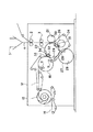
これは、図4に示すように、三角板1により2つに折られたウェブaを、ウェブaの走行速度と同じ周速度で回転している一対の第1ニッピングローラ2の間と一対の第2ニッピングローラ3の間とを経て第1カッタ胴21と折胴23との間へ送り、折胴23のカッタ受け34’と第1カッタ胴21の各鋸刃30とよりなる断裁装置により、紙幅方向に断続的に切断する[図5の(a)参照]。
【0008】
この時、胴廻り搬送ベルト24が折胴23の下部外周面に接触しながら循環移動しており、上記紙幅方向に断続的に切断したウェブaを折胴23の下部外周面と胴廻り搬送ベルト24とにより挾んで、第2カッタ胴26と折胴23との間へ送り、折胴23のカッタ受け34’と第2カッタ胴26の各鋸刃31とによりなる断裁装置により、残りの部分(胴廻り搬送ベルト24の各細幅ベルトの間の部分)を紙幅方向に切断する[図5の(b)参照]。
【0009】
そして、この全幅を切断したウェブaの先端を先端用押え込み胴27の押え込みブレード28{胴廻り搬送ベルト24に干渉させないように先端部を紙幅方向に切り欠いた押え込みブレード28[図5の(c)参照]}により、折胴23に取り付けた各爪32と同折胴23に取り付けた各爪座33との間に押し込む。
【0010】
このとき、折胴23の爪座33の側面近傍には、干渉するものがないので、ウェブaの先端を折胴23の中へ支障なく押し込むことができる。また、各押え込みブレード28、各爪32、各爪座33のそれぞれは折胴23に同列に一直線状に配置されており、爪32と爪座33との間に押し込まれたウェブaの先端は、ラジアル方向に折り曲げられた状態でくわえられる。
【0011】
そして、折胴23によりくわえたウェブaを、折胴23とともにさらに回転、移動させ、ウェブaの後端(尻側)を第2カッタ胴26により切断して、切り離し、折胴23の折ブレード29により、この切り離した折丁の中央部をくわえ胴10のくわえ装置11へ挿入するとき、折丁の先端をくわえていた折胴23の爪32を開き、折丁を切断面に平行に2つ折りにし、その後、搬送ベルト12→排紙羽根車13→排紙コンベア14を経て折機外へ搬出する。
【0012】
これによれば、上述した増速一段ピンレス折機のようにウェブaを増速搬送ベルト間で滑らす必要がないので、ウェブa上の印刷された絵柄にベルト傷等の印刷障害を生じさせない。また、静電気の発生も少なく、折精度を向上できて、排紙コンベア14上に排出される紙の姿勢を容易に矯正できる。更に、ウェブaを増速搬送ベルトにより増速させる必要がないので、ベルト圧の調整を行う必要がなく、紙詰まりを殆ど解消できて、稼働率を向上できる。等の利点が得られる。
【0013】
【発明が解決しようとする課題】
ところが、上述した従来のピンレス折機は、以下のような問題点がある。
即ち、
▲1▼ 2回にわたって断裁工程(2段断裁)を行うため、切断面が凹凸となり[図5の(d)参照]、後工程(デリバリー)で紙詰まりし易いとともに、紙集積結束装置(スタッカーバンドラーと言う)における紙揃えが悪い。
▲2▼ 切断面が凹凸にならないよう、第1断裁と第2断裁の間に位相調整機構を構成しても、低,高速差による紙の状態差や紙質変更時による紙の動きの変化により、断裁位相の調整が機械立ち上がり時と増速時に必要となり、調整が面倒であるとともに、ヤレ紙が多くなる。
▲3▼ 第1断裁胴,第2断裁胴,先端用押え込み胴と構成部品が多く、保守,管理が面倒であるとともに装置が大型化する。
【0014】
そこで、本発明の目的は、1段断裁することにより、品質の向上と部品点数の削減が図れるピンレス折機を提供することにある。
【0015】
【課題を解決するための手段】
前記目的を達成するために、本発明に係るピンレス折機は、第1の胴に押え込みブレードを備え、該第1胴に対接する第2の胴に前記押え込みブレードで押え込まれた紙を保持するための爪部材を備えたピンレス折機において、前記第1及び第2胴に紙押え部材を付設すると共にいずれか一方の胴に紙の全幅に亙って切断し得る断裁刃を設けたことを特徴とする。
また、前記第1の胴又は前記第2の胴のうち少なくとも一方の前記押え部材は、胴の外周に設けられ円周方向に並設された一対の紙押えから構成され、一方の紙押えにより切断された折丁後端が押えられ、他方の紙押えにより後続のウェブの先端が押えられることを特徴とする。
また、前記一対の紙押えは前記断裁刃を挟むように配設されていることを特徴とする。
また、前記第1の胴の前記紙押え部材は前記押え込みブレードを挟むように設けられた一対の紙押えであり、前記第2の胴の前記紙押え部材は前記爪部材を挟むように設けられた一対の紙押えであることを特徴とする。
【0016】
[作用]
前記構成によれば、第1及び第2胴間に送り込まれてきた紙は、1段にて完全切断された直後にその後続紙の先端が爪部材にて保持されて先行紙と紙間隔を拡げずに搬送される。
【0017】
【発明の実施の形態】
以下、本発明に係るピンレス折機を実施例により詳細に説明する。
【0018】
[実施例]
図1は輪転印刷機のピンレス折機の一実施例を示す概略構成図、図2はその要部拡大図、図3は動作説明図である。これらの図において、図4と同一部材には同一符号を付して重複する説明は省略する。
【0019】
図1に示すように、三角板1により2つに折られたウェブaは、ウェブaの走行速度と同じ周速度で回転している第1ニッピングローラ2及び第2ニッピングローラ3を経て断裁胴40と折胴41との間へ送られ、ここで1段にて切断されるようになっている。
【0020】
そして、断裁された折丁は、折胴41とくわえ胴10にて従前通り一回平行折りされた後、搬送ベルト12により図外の排紙装置へと送られるようになっている。
【0021】
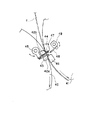
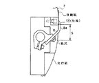
前記断裁胴40は、図2にも示すように、その外周一部に前後一対の紙押え42a,42bと断裁刃43とからなる断裁装置が組み付けられると共に、前記紙押え42a,42b間には、断裁刃43より回転方向下流側に位置して、切断されたウェブaの先端を折胴41に押え込む押え込みブレード44が配置される。
【0022】
前記断裁刃43は、ウェブaの全幅に亙って切断し得る一枚刃で形成されると共に、前記押え込みブレード44は、支持レバー45を介して折曲位置(押え込み位置)と待機位置との間を揺動可能に支持されている。
【0023】
前記折胴41は、その外周一部に断裁受け(紙押え)46とこの断裁受け46より回転方向下流側に位置してくわえ顎(紙押え)47が固設されると共に、くわえ顎47に対応して押え込みブレード44により押え込まれたウェブaの先端をくわえるくわえ板48が支持レバー49によりくわえ位置と待機位置との間を揺動可能に支持されている。
【0024】
そして、前記押え込みブレード44と爪部材としてのくわえ板48とは、先端部同志が互いに干渉しないように、紙幅方向に千鳥配列されている。
【0025】
このように構成されたピンレス折機の作用を図3を参照して説明する。
先ず、図3の(a)に示すように、ニッピングローラにて送り込まれたウェブaは、同ウェブaの搬送速度と等速の周速にて回転する断裁胴40と折胴41との間に入り、一枚刃の断裁刃43により全幅に亙って1回で切断される。この際、切断された折丁後端と後続のウェブa先端とはそれぞれ紙押え42a,42bにて保持されている。
【0026】
次に、図3の(b)に示すように、上記切断後に押え込みブレード44が揺動し、後続のウェブa先端が折胴41の断裁受け46とくわえ顎47との間に押し込まれる。
【0027】
この後、図3の(c)に示すように、くわえ板48が揺動して閉じ、くわえ顎47との間で上記後続のウェブa先端をくわえる。
その後、ウェブaは折胴41に巻かれてくわえ胴10との間に入り、ここで従前通り一回平行折りされる。
【0028】
このようにして本実施例では、一枚刃の断裁刃43により全幅に亙って1回で切断されるので、従来の2段断裁のように切断面が凹凸にならず、後工程の紙集積結束装置における紙揃えが良好となる。
【0029】
また、断裁胴40が一個で済むと共に、この断裁胴40に押え込みブレード44を併設して従来の先端用押え込み胴27を無くしたので、部品点数の削減により保守,管理が容易となると共に、コスト及びスペースの面で頗る有効である。
【0030】
尚、本発明は上記実施例に限定されず、上記実施例における断裁胴40を断裁受胴に構成して折胴41側に断裁刃43を設けても良い。
【0031】
また、上記実施例における3胴式に代えて、折胴とくわえ胴との2胴式に構成し、折胴にくわえ板を、またくわえ胴に押え込みブレードを設けると共に、断裁刃を折胴とくわえ胴とのいずれか一方に設けるようにしても良い。
【0032】
また、上記実施例において、押え込みブレード44とくわえ板48とを紙幅方向に千鳥配列したが、押え込みブレード44をウェブa先端を押さえ込むきっかけだけ得られるように短く形成してくわえ板48と干渉しなければ千鳥配列にする必要はない。勿論、従来のように搬送ベルトが存在しないので、押え込みブレード44とくわえ板48とは一枚板でも良い。
【0033】
また、機械構成によっては、切断されたウェブの先端を増速させるように構成してもよい。
【0034】
【発明の効果】
以上説明したように本発明によれば、第1の胴に押え込みブレードを備え、該第1胴に対接する第2の胴に前記押え込みブレードで押え込まれた紙を保持するための爪部材を備えたピンレス折機において、前記第1及び第2胴に紙押え部材を付設すると共にいずれか一方の胴に紙の全幅に亙って切断し得る断裁刃を設けたので、第1及び第2胴間に送り込まれてきた紙は1段断裁されることになり、品質の向上と部品点数の削減が図れる。
【図面の簡単な説明】
【図1】本発明に係るピンレス折機の一実施例を示す概略構成図である。
【図2】同じく要部拡大図である。
【図3】同じく動作説明図である。
【図4】従来のピンレス折機の概略構成図である。
【図5】同じくピンレス折機の不具合を示す説明図である。
【図6】異なった従来の増速一段ピンレス折機の概略構成図である。
【図7】同じく要部拡大図である。
【符号の説明】
1 三角板
2 第1ニッピングローラ
3 第2ニッピングローラ
40 断裁胴
41 折胴
42a,42b 紙押え
43 断裁刃
44 押え込みブレード
46 断裁受け
47 くわえ顎
48 くわえ板
a ウェブ[0001]
BACKGROUND OF THE INVENTION
The present invention relates to a pinless folder of a rotary printing press.
[0002]
[Prior art]
As a pinless folding machine for a rotary printing press, for example, those shown in FIGS. 6 and 7 are known. To explain this, reference numeral 1 in FIG. 6 is a triangular plate, and a pair of webs a (or unbent webs b) folded in two by the triangular plate 1 are rotated at the same peripheral speed as the traveling speed of the web a. The sheet is sent between the
[0003]
The cut web a is rapidly accelerated by the pair of speed-up
[0004]
Then, the holding plate and the holding seat of the holding device 11 of the
[0005]
However, such a pinless folder has the following problems. That is,
(1) After cutting the web a, the web a is accelerated more rapidly than the running speed of the web a (by about 15 to 40%). Paper edge breakage tends to occur at both ends of the protruding paper. Also, the paper is easy to tilt, and troubles such as poor folding accuracy are likely to occur.
(2) Since the web a that is slid while running between the speed-increasing
{Circle around (3)} Since the web a is slid between the speed-up
(4) Since the web a is slid between the speed-up
(5) Since the web a is slid and cut between the speed-up
(6) When the web a guided to the folding
(7) Since the leading edge of the web a increased in speed is gripped by a plurality of
The phenomena of the above items (1) to (7) become worse as the folder speeds up.
[0006]
In order to solve the above problems, a pinless folder has been proposed in Japanese Patent Application Laid-Open No. 7-61705.
[0007]
As shown in FIG. 4, the web a folded in two by the triangular plate 1 is rotated between the pair of
[0008]
At this time, the
[0009]
Then, the leading end of the web a having the entire width cut is the
[0010]
At this time, since there is no interference in the vicinity of the side surface of the
[0011]
Then, the web a held by the folding
[0012]
According to this, since it is not necessary to slide the web a between the speed-acceleration conveyance belts as in the above-described speed-up one-stage pinless folding machine, printing troubles such as belt scratches do not occur on the printed pattern on the web a. Further, the generation of static electricity is small, folding accuracy can be improved, and the posture of the paper discharged onto the
[0013]
[Problems to be solved by the invention]
However, the conventional pinless folder described above has the following problems.
That is,
(1) Since the cutting process (two-stage cutting) is performed twice, the cut surface becomes uneven [see (d) of FIG. 5], and the paper is easily jammed in the subsequent process (delivery). The paper alignment in Bundler) is bad.
(2) Even if the phase adjustment mechanism is configured between the first cutting and the second cutting so that the cut surface does not become uneven, due to the difference in the state of the paper due to the low and high speed differences and the change in the paper movement due to the paper quality change The trimming phase needs to be adjusted when the machine is started up and when the speed is increased, which is troublesome and increases the amount of paper.
(3) There are many components such as the first cutting cylinder, the second cutting cylinder, the tip pressing cylinder, and the maintenance and management are troublesome and the apparatus becomes large.
[0014]
Therefore, an object of the present invention is to provide a pinless folding machine that can improve quality and reduce the number of parts by cutting one stage.
[0015]
[Means for Solving the Problems]
In order to achieve the above object, a pinless folding machine according to the present invention includes a pressing blade in a first cylinder, and holds the paper pressed by the pressing blade in a second cylinder that is in contact with the first cylinder. In a pinless folding machine provided with a claw member, a paper pressing member is attached to the first and second cylinders, and a cutting blade capable of cutting over the entire width of the paper is provided on one of the cylinders. It is characterized by.
The at least one pressing member of the first cylinder or the second cylinder includes a pair of paper pressers provided on the outer periphery of the cylinder and arranged in the circumferential direction. The trailing end of the cut signature is pressed, and the leading edge of the subsequent web is pressed by the other paper presser.
Further, the pair of paper presses are arranged so as to sandwich the cutting blade.
Further, the paper pressing member of the first cylinder is a pair of paper pressing elements provided so as to sandwich the pressing blade, and the paper pressing member of the second cylinder is provided so as to sandwich the claw member. A pair of paper pressers.
[0016]
[Action]
According to the above configuration, immediately after the paper fed between the first and second cylinders is completely cut in one stage, the leading edge of the succeeding paper is held by the claw member so that the paper distance from the preceding paper is increased. It is conveyed without spreading.
[0017]
DETAILED DESCRIPTION OF THE INVENTION
Hereinafter, the pinless folder according to the present invention will be described in detail with reference to examples.
[0018]
[Example]
FIG. 1 is a schematic configuration diagram showing an embodiment of a pinless folding machine of a rotary printing press, FIG. 2 is an enlarged view of a main part thereof, and FIG. In these drawings, the same members as those in FIG.
[0019]
As shown in FIG. 1, the web a folded in two by the triangular plate 1 passes through the
[0020]
The cut signature is folded once in parallel by the
[0021]
As shown in FIG. 2, the cutting
[0022]
The
[0023]
The
[0024]
The
[0025]
The operation of the pinless folder configured as described above will be described with reference to FIG.
First, as shown in FIG. 3A, the web a fed by the nipping roller is between a cutting
[0026]
Next, as shown in FIG. 3B, the
[0027]
Thereafter, as shown in FIG. 3C, the holding
Thereafter, the web a is wound around the
[0028]
In this way, in this embodiment, the single-
[0029]
In addition, since only one
[0030]
In addition, this invention is not limited to the said Example, The cutting
[0031]
Further, instead of the three-cylinder type in the above-described embodiment, a two-cylinder type consisting of a folding cylinder and a holding cylinder is provided, a holding plate is provided in the folding cylinder, a pressing blade is provided in the holding cylinder, and a cutting blade is provided as a folding cylinder. You may make it provide in any one of a holding body.
[0032]
In the above embodiment, the holding
[0033]
Further, depending on the machine configuration, the leading end of the cut web may be accelerated.
[0034]
【The invention's effect】
As described above, according to the present invention, the first cylinder is provided with the pressing blade, and the second cylinder contacting the first cylinder is provided with the claw member for holding the paper pressed by the pressing blade. In the provided pinless folding machine, a paper pressing member is attached to the first and second cylinders, and a cutting blade capable of cutting over the entire width of the paper is provided on one of the first and second cylinders. The paper that has been fed between the cylinders is cut by one stage, so that the quality can be improved and the number of parts can be reduced.
[Brief description of the drawings]
FIG. 1 is a schematic configuration diagram showing an embodiment of a pinless folder according to the present invention.
FIG. 2 is an enlarged view of the main part of the same.
FIG. 3 is also an operation explanatory view.
FIG. 4 is a schematic configuration diagram of a conventional pinless folder.
FIG. 5 is an explanatory view showing a problem of the pinless folder.
FIG. 6 is a schematic configuration diagram of a different conventional speed-up single-stage pinless folder.
FIG. 7 is an enlarged view of the main part of the same.
[Explanation of symbols]
DESCRIPTION OF SYMBOLS 1
Claims (4)
前記第2の胴の前記紙押え部材は前記爪部材を挟むように設けられた一対の紙押えであることを特徴とする請求項1記載のピンレス折機。 The pinless folder according to claim 1, wherein the paper pressing member of the second body is a pair of paper pressing members provided so as to sandwich the claw member.
Priority Applications (1)
| Application Number | Priority Date | Filing Date | Title |
|---|---|---|---|
| JP27680897A JP3843173B2 (en) | 1996-10-15 | 1997-10-09 | Pinless folding machine |
Applications Claiming Priority (3)
| Application Number | Priority Date | Filing Date | Title |
|---|---|---|---|
| JP8-271932 | 1996-10-15 | ||
| JP27193296 | 1996-10-15 | ||
| JP27680897A JP3843173B2 (en) | 1996-10-15 | 1997-10-09 | Pinless folding machine |
Publications (2)
| Publication Number | Publication Date |
|---|---|
| JPH10175770A JPH10175770A (en) | 1998-06-30 |
| JP3843173B2 true JP3843173B2 (en) | 2006-11-08 |
Family
ID=26549952
Family Applications (1)
| Application Number | Title | Priority Date | Filing Date |
|---|---|---|---|
| JP27680897A Expired - Fee Related JP3843173B2 (en) | 1996-10-15 | 1997-10-09 | Pinless folding machine |
Country Status (1)
| Country | Link |
|---|---|
| JP (1) | JP3843173B2 (en) |
-
1997
- 1997-10-09 JP JP27680897A patent/JP3843173B2/en not_active Expired - Fee Related
Also Published As
| Publication number | Publication date |
|---|---|
| JPH10175770A (en) | 1998-06-30 |
Similar Documents
| Publication | Publication Date | Title |
|---|---|---|
| EP0836938B1 (en) | Pinless folder | |
| US5547452A (en) | Method and apparatus for cross-folding signatures | |
| JP2675565B2 (en) | Pinless folding method and device | |
| US5174557A (en) | Apparatus for stapling multipart printed products | |
| EP0132763A2 (en) | Sheet diverting system | |
| JP2672332B2 (en) | Device for diverting the flow of printed books | |
| US5484379A (en) | Folder assemby for printing press | |
| US5028045A (en) | Apparatus for taking over printing products from a rotatably driven paddle wheel of a printing machine | |
| JP2516640Y2 (en) | Paper dodger | |
| JPS5920587B2 (en) | Folding machine in rotary printing press | |
| JP3843173B2 (en) | Pinless folding machine | |
| US6705981B2 (en) | Device for retention of products on a transporting surface in a folder | |
| US6612213B1 (en) | Double-cut lobed belt diverter | |
| JP2893340B2 (en) | Signature distribution device for rotary printing press | |
| JP3241180B2 (en) | Pinless folding machine for rotary printing press | |
| JP3241187B2 (en) | Signature making method and apparatus | |
| JP3652897B2 (en) | Defective paper discharge device for folding machine | |
| JPH0647427B2 (en) | Origami member switching device for folder | |
| JP3652885B2 (en) | Rotary press folding machine | |
| JP2550776Y2 (en) | Rotary printing press folding machine | |
| JPH0761704A (en) | Pinless folder for rotary printing machine | |
| JP2722000B2 (en) | Ajiro device of folding machine | |
| JPH042935Y2 (en) | ||
| JP2535158Y2 (en) | Folding machine for web press | |
| JPH1129259A (en) | Chopper folding machine for web press |
Legal Events
| Date | Code | Title | Description |
|---|---|---|---|
| A521 | Written amendment |
Free format text: JAPANESE INTERMEDIATE CODE: A523 Effective date: 20040921 |
|
| A621 | Written request for application examination |
Free format text: JAPANESE INTERMEDIATE CODE: A621 Effective date: 20040921 |
|
| A977 | Report on retrieval |
Free format text: JAPANESE INTERMEDIATE CODE: A971007 Effective date: 20060803 |
|
| TRDD | Decision of grant or rejection written | ||
| A01 | Written decision to grant a patent or to grant a registration (utility model) |
Free format text: JAPANESE INTERMEDIATE CODE: A01 Effective date: 20060808 |
|
| A61 | First payment of annual fees (during grant procedure) |
Free format text: JAPANESE INTERMEDIATE CODE: A61 Effective date: 20060814 |
|
| R150 | Certificate of patent or registration of utility model |
Free format text: JAPANESE INTERMEDIATE CODE: R150 |
|
| FPAY | Renewal fee payment (event date is renewal date of database) |
Free format text: PAYMENT UNTIL: 20090818 Year of fee payment: 3 |
|
| FPAY | Renewal fee payment (event date is renewal date of database) |
Free format text: PAYMENT UNTIL: 20100818 Year of fee payment: 4 |
|
| FPAY | Renewal fee payment (event date is renewal date of database) |
Free format text: PAYMENT UNTIL: 20110818 Year of fee payment: 5 |
|
| LAPS | Cancellation because of no payment of annual fees |