JP3842115B2 - Rotation angle detection device and rotation angle detection method - Google Patents
Rotation angle detection device and rotation angle detection method Download PDFInfo
- Publication number
- JP3842115B2 JP3842115B2 JP2001367367A JP2001367367A JP3842115B2 JP 3842115 B2 JP3842115 B2 JP 3842115B2 JP 2001367367 A JP2001367367 A JP 2001367367A JP 2001367367 A JP2001367367 A JP 2001367367A JP 3842115 B2 JP3842115 B2 JP 3842115B2
- Authority
- JP
- Japan
- Prior art keywords
- rotation angle
- region
- angle
- absolute
- magnetic sensors
- Prior art date
- Legal status (The legal status is an assumption and is not a legal conclusion. Google has not performed a legal analysis and makes no representation as to the accuracy of the status listed.)
- Expired - Fee Related
Links
Images


Description
【0001】
【発明の属する技術分野】
本発明は、例えば自動車のステアリングのような回転体の回転角度を検出する回転角度検出装置及び回転角度検出方法に関する。
【0002】
【従来の技術】
一般的に自動車のステアリングは、中立位置から左右両方向に2回転弱回転し、このような回転体の回転角度を検出する従来の回転角度検出装置としては、図7に示すものがある。この回転角度検出装置50は、図7に示すように、ステアリングと一体に回転する第1歯車51と、この第1歯車51に噛み合う第2歯車52と、この第2歯車52に同軸で固定された第3歯車53と、この第3歯車53に噛み合う第4歯車54と、この第4歯車54に固定され、第4歯車と共に回転するマグネット(図示せず)とこのマグネットの回転角度に応じて被検出位置における磁束密度をリニア変化させる固定子(図示せず)とを有する磁界発生手段55と、この磁界発生手段55の被検出位置に配置され、磁界発生手段55の磁界強度を検出するホール素子(図示せず)とを備えている。
【0003】
この回転角度検出装置50によれば、ステアリングの最大角の回転が上述の歯車群によって360度以下に減速され、この減速回転に応じて磁界発生手段55がホール素子に対してリニア変化する磁束密度の磁束を発生し、この磁束密度をホール素子が検出することによりステアリングの回転角度の検出を行っている。従って、ステアリングの回転角度に対してホール素子(図示せず)よりリニアな出力が得られる。
【0004】
【発明が解決しようとする課題】
しかしながら、前記従来の回転角度検出装置50では、リニア変化する磁束密度を得るために磁界発生手段55の固定子(図示せず)に軟磁性体を使用するため、磁界発生手段55の磁化特性にはヒステリシスが発生する。従って、回転方向が変化した場合に、ヒステリシスによって回転角度に応じた所望の磁束密度が発生せず、角度検出に誤差が発生するという問題がある。
【0005】
又、磁界発生手段55に発生させる磁束密度の強度と角度が比例関係にあることを利用し、磁束密度の絶対値を基準として角度検出を行っている。従って、長期的な使用等によって磁界発生手段55内のマグネット(図示せず)の磁力が落ちて磁束密度が低くなると、角度検出に誤差が発生するという問題がある。
【0006】
そこで、本発明は、前記した課題を解決すべくなされたものであり、回転方向が変化した場合、及び、長期的な使用等でマグネットの磁力が低下した場合にも検出誤差が発生しない検出回転角度検出装置を提供することを目的とする。
【0007】
【課題を解決するための手段】
請求項1の発明は、固定体に対して正逆両方向に回転する回転体の回転角度を検出する回転角度検出装置であって、前記回転体に連動して回転し、180度の回転角度範囲でN極とS極の2極に着磁されたマグネット体と、このマグネット体の対向位置で、且つ、180度の回転角度範囲内に等間隔に配置され、前記マグネット体の磁界強度を検出するN個(N≧3)の磁気センサと、このN個の磁気センサの検出出力の絶対値を比較し、絶対値の最小値を示す磁気センサの領域毎に区分けすることにより2N個の領域に分類し、この2N個の各領域に対応する前記磁気センサ及び各領域の絶対角度についての領域角度を予め取得し、N個の前記磁気センサの検出出力の絶対値より最小値を出力する磁気センサを特定し、且つ、この特定した磁気センサの左右に隣接する2つの磁気センサの出力値の大小より領域判定を行い、この領域判定された当該領域の磁気センサの出力値と左右に隣接する2つの磁気センサの出力値との相対比較演算より、当該領域内における領域内角度を算出し、この領域内角度と当該領域までの領域外角度とにより絶対角度を算出したことを特徴とする。
【0008】
この回転角度検出装置では、着磁されたマグネット体の磁束密度を複数の磁気センサが検出し、この検出出力より絶対角度を算出し、又、複数の磁気センサの出力レベルを相対比較することで絶対角度を検出する。
【0009】
請求項2の発明は、請求項1記載の回転角度検出装置であって、N個の前記磁気センサは、5個であることを特徴とする。
【0010】
この回転角度検出装置では、請求項1の発明の作用に加え、360度が10個の領域に分類され、磁気センサの検出出力のほぼリニアな特性線が得られる範囲を用いて回転角度の算出がなされる。
【0011】
請求項3の発明は、請求項1又は請求項2記載の回転角度検出装置であって、前記した相対比較演算は、左右の隣接する磁気センサの出力値の絶対値の合計をX、当該領域の磁気センサの出力をICn、領域内角度をθ1とすると、(ICn/X)×b=θ1(但し、bは所定の係数)であることを特徴とする。
【0012】
この回転角度検出装置では、請求項1又は請求項2の発明の作用に加え、比較的簡単な演算式で領域内の回転角度を容易に算出できる。
【0013】
請求項4の発明は、請求項1〜請求項3記載の回転角度検出装置であって、前記マグネット体は、リング形状であり、その円周面に着磁されていることを特徴とする。
【0014】
この回転角度検出装置では、請求項1〜請求項3の発明と同様の作用が得られる。
【0015】
請求項5の発明は、請求項4記載の回転角度検出装置であって、N個の前記磁気センサは、リング状の前記マグネット体の内周側に配置されていることを特徴とする。
【0016】
この回転角度検出装置では、請求項4の発明の作用に加え、N個の磁気センサがマグネット体の内部に配置される。
【0017】
請求項6の発明は、請求項1〜請求項5記載の回転角度検出装置であって、前記マグネット体は、前記固定体に対して360度以上の回転角度で両方向に回転する前記回転体を減速機構により360度未満に変換されて回転するものであることを特徴とする。
【0018】
この回転角度検出装置では、請求項1〜請求項5の発明の作用に加え、360度以上回転する回転体の回転角度を検出できる。
【0019】
請求項7の発明は、固定体に対して正逆方向に回転する回転体に連動して回転し180度の回転角度範囲でN極とS極の2極に着磁されたマグネット体と、このグネット体の対向位置で、且つ180度の回転角度範囲内に等間隔に配置され前記マグネット体の磁界強度を検出するN個(N≧3)の磁気センサとを備えた回転角度検出装置における回転角度検出方法であって、N個の磁気センサの検出出力の絶対値を比較し、絶対値の最小値を示す磁気センサの領域毎に区分けすることにより2N個の領域に分類し、この2N個の各領域に対応する前記磁気センサ及び各領域の絶対角度についての領域角度を予め取得し、N個の前記磁気センサの検出出力の絶対値より最小値を出力する磁気センサを特定し、且つ、この特定した磁気センサの左右に隣接する2つの磁気センサの出力値の大小より領域判定を行い、この領域判定された当該領域の磁気センサの出力値と左右に隣接する2つの磁気センサの出力値との相対比較演算により、当該領域内における領域内角度を算出し、この領域内角度と当該領域までの領域外角度とにより絶対角度を算出することを特徴とする。
【0020】
この回転角度検出装置では、着磁されたマグネット体の磁束密度を複数の磁気センサで検出し、これらの磁気センサの検出出力から絶対角度を算出して、複数の磁気センサの出力レベルを相対的に比較することで絶対角度を検出する。
【0021】
請求項8の発明は、請求項7記載の回転角度検出方法であって、前記相対比較演算は、左右の隣接する磁気センサ(IC1)〜(IC5)の出力値の絶対値の合計をXとし、当該領域の磁気センサの出力をICn、領域内角度をθ1としたとき、(ICn/X)×b=θ1(但し、bは所定の係数)であることを特徴とする。
【0022】
この回転角度検出装置では、請求項7の発明の作用に加え、比較的簡単な演算式で領域内の回転角度を容易に算出することができる。
【0023】
【発明の実施の形態】
以下、本発明の一実施形態を図面に基づいて説明する。
【0024】
図1〜図6は本発明の一実施形態を示し、図1(a)は回転角度検出装置の一部切欠平面図、図1(b)は回転角度検出装置の断面図、図2はマグネット体とこのマグネット体の近接位置に配置されるホール素子の配置状態を示す図、図3はホール素子の出力特性線図、図4はホール素子の出力特性線において直線からのずれ量を示す特性線図、図5は領域3の第1〜第3ホール素子の特性線図、図6は領域3の絶対角度における各ホール素子の出力、X、θ1等の値を示す図である。
【0025】
図1(a)、(b)に示すように、回転角度検出装置1は、センサケース2内に収容された減速歯車機構3を有する。この減速歯車機構3は、固定体である車体(図示せず)に対し回転体であるステアリング(図示せず)と一体に回転する第1歯車4と、この第1歯車4に噛み合う第2歯車5と、この第2歯車5に同軸で固定された第3歯車6と、この第3歯車6に噛み合う第4歯車7とから構成されており、ステアリング(図示せず)の回転を約1/4に減速することによってステアリング(図示せず)の最大角の回転を360度以下の回転とする。
【0026】
マグネット体8は、第4歯車7の下面に固定され、第4歯車と共に回転する。マグネット体8の近接下方には回路基板9が配置され、この回路基板9には磁気センサであるホール素子IC1〜IC5が5箇所に固定されている。この各ホール素子IC1〜IC5の検出出力は、演算手段10に導かれており、演算手段10はホール素子IC1〜IC5の検出出力より回転角度を算出する。この演算内容については、後述する。
【0027】
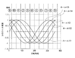
次に、マグネット体8と5個のホール素子IC1〜IC5について説明する。図2に示すように、マグネット体8は、リング状に形成され、N極とS極の2極に平行着磁されている。つまり、1極が180度の回転角度範囲に亘って形成され、180度対向位置に着磁の境界が設けられている。図2では、リング状のマグネット体8の内周面の着磁方向が矢印で示され、内周面に矢印の先端が向かっている場合がN極に、内周面に矢印の根元が向いている場合がS極に着磁されていることを示す。ホール素子IC1〜IC5は、マグネット体8の内周面の対向位置で、且つ、180度の回転角度範囲内に等間隔(36度間隔)に配置されており、マグネット体8の磁界強度に応じた電圧を出力する。各ホール素子IC1〜IC5の検出出力は、図3に示すように、隣接するホール素子IC1〜IC5に対して36度の位相差を有するサイン波形を示す。図3では、サイン波形の検出出力を−1〜+1の大きさに規格化してあり、図3の出力0のポイントがマグネット体8の磁極の境界の検出位置になる。
【0028】
次に、演算手段10の演算内容(回転角度検出方法)を説明する。5個のホール素子IC1〜IC5の検出出力の絶対値を比較し、絶対値の最小値を示すホール素子IC1〜IC5の領域毎に区分けする。これにより図3に示すように、10個の領域に分類され、この10個の各領域に対応するホール素子IC1〜IC5及び各領域の絶対角度についての角度(領域外角度)を予め取得する。つまり、領域1はホール素子IC4が最小値を示し、絶対角度で54度〜90度の範囲、領域2はホール素子IC3が最小値を示し、絶対角度で90度〜126度の範囲、領域3はホール素子IC2が最小値を示し、絶対角度で126度〜162度の範囲、領域4はホール素子IC1が最小値を示し、絶対角度で162度〜198度の範囲、の如くである。演算手段10は、この領域データを保持している。
【0029】
そして、5個のホール素子IC1〜IC5の検出出力の絶対値を比較してその最小値を出力するホール素子IC1〜IC5を特定する。ここで、同じホール素子IC1〜IC5で2つの領域が存在するため、特定したホール素子IC1〜IC5の左右に隣接する2つのホール素子IC1〜IC5の出力値の大小よりどちらの領域かを判定する。つまり、N番目のホール素子IC1〜IC5の出力をホールICnとすると、ホールICnの出力>ホールICn+1の場合は、領域1〜領域5の間と判定し、ホールICnの出力<ホールICn+1の場合は、領域6〜領域10の間と判定する。但し、n+1の最大は6であり、ホールIC6=ホールIC1とする。
【0030】
次に、領域判定された当該領域のホール素子IC1〜IC5の出力値と左右に隣接する2つのホール素子IC1〜IC5の出力値との相対比較演算より、当該領域内における角度(領域内角度)θ1を算出する。各領域幅は36度であり、この領域内での角度演算は、次の手順で±18度の値に直す。
【0031】
つまり、絶対値の最小値を示すホール素子IC1〜IC5の出力をホールICnとすると、(ホールICn−1の絶対値)+(ホールICn+1の絶対値)=Xを演算し、次に、(ホールICn/X)×b=θ1を演算する。
【0032】
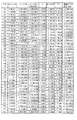
ここで、bは係数であり、図6より約65.1になる。上記式より領域幅36度の範囲をほぼリニアな±18度の値に変換できる。ここで、上記演算式について説明する。絶対値の最小値を示すホール素子IC1〜IC5の出力は、着磁境界の検出ポイントでゼロであり、このポイントを0度とする±18度の領域は、図4に示すリニアニティ(直線からのずれ)の特性線で分かるように、サイン波形では元々かなりの直線性を保有している。そして、領域3を例にすると、当該領域で最小値を示すホール素子IC2の左右に隣接するホール素子IC1,IC3の特性線は、図5に示すように、ホールセンサIC2の特性線に対して所定量だけ±方向にシフトしたものとなり、左右に隣接するホール素子IC1,IC3の出力値の合計であるXは、図6に示すように、領域内でほぼ一定値を示す。この一定値は、マグネット体8の磁力に応じて変化するため、(ホールICn/X)の演算によりホール素子IC3の各角度における比較値、つまり、マグネット体8の磁力低下の影響を受けない比較値が算出される。例えばマグネット体8の磁力が低下して磁束密度がY%になったと仮定すると、Xの値がX・Yとなり、ホールICnの出力がホールICn×Yとなり、上記式(ホールICn/X)の演算結果が同じ値(比較値)となる。こような比較値に対し、ホール素子IC3の126度におけるθ1の値が18度になるように係数(b=65.1)を掛ければ、マグネット体8の磁力低下の影響を受けない領域内角度θ1を求めることができる。図6に示すように、領域内角度θ1の値は、直線からの誤差0.3度未満に抑えられている。
【0033】
次に、図3に示すように、領域1〜領域4及び領域10の場合には角度増加に対してXが減少するため、θ1=θ1×−1とすることで角度増加に対しθ1も増加するようにする。
【0034】
次に、当該領域までの領域外角度θ2を算出する。領域内角度θ1の基準点(値がゼロのポイント)は、各領域の中間点であるため、この中間点までの角度が領域外角度θ2となる。領域外角度θ2は、領域の番号をmとすると、領域外角度θ2は、θ2=m×36+36の演算により求まる。但し、領域10の場合にはθ2=36とする。
【0035】
絶対角θは、領域内角度θ1と当該領域までの領域外角度θ2との合計により求まるため、θ=θ1+θ2の式より算出する。
【0036】
以上により、360度内の絶対角θが演算され、このθを歯車減速機構3の減速比を考慮してステアリング(図示せず)の絶対舵角を求めることができる。
【0037】
この回転角度検出装置1では、着磁されたマグネット体8の磁束密度を5個のホール素子IC1〜IC5が検出し、この検出出力より絶対角度を算出するため、回転方向が変化した場合にヒステリシスによる検出誤差が発生しない。つまり、従来例では軟磁性体の発生する磁束密度を検出していたため、ヒステリシスによる悪影響を受けたが、本発明では軟磁性体を使用しないため、ヒステリシスにより悪影響を受けることなく角度検出できる。又、5個のホール素子IC1〜IC5の出力レベルを相対比較することで絶対角度を検出するため、長期的な使用等でマグネット体8の磁力が低下した場合にも検出誤差が発生しない。つまり、従来例ではマグネット体の磁束密度の強度と角度とが比例関係にあることを利用し、検出出力の絶対値を基準に回転角度を検出していたため、マグネット体の磁力低下による検出誤差があったが、本発明ではマグネット体8の磁束密度の強度と角度とが比例関係にあることは利用しているが、複数のホール素子IC1〜IC5の出力レベルを相対比較することで絶対角度を検出するため、マグネット体8の磁力低下による検出誤差が発生しない。
【0038】
この実施形態では、磁気センサであるホール素子IC1〜IC5は、その個数をNとすると、Nが5個であるので、360度が10個の領域に分類され、ホール素子IC1〜IC5の検出出力のほぼリニアな特性線が得られる範囲を用いて回転角度の算出がなされるため、回転角度が高精度に検出できる。又、ホール素子IC1〜IC5の個数は3以上(N≧3)であれば良いが、ホール素子IC1〜IC5の個数は多ければ多いほど精度上好ましい。つまり、ホール素子IC1〜IC5の個数が多いと、ホール素子IC1〜IC5の検出出力の内で更にリニアな特性線が得られる範囲を用いて回転角度の算出がなされるため、検出精度が向上する。又、この実施形態では、磁気センサとしてホール素子IC1〜IC5を用いたが、マグネット体8からの磁界強度を検出するものであれば良く、例えば磁界強度を抵抗値に変換する素子を用いても良い。
【0039】
この実施形態では、演算処理回路(図示せず)による相対比較演算は、左右の隣接するホール素子IC1〜IC5の出力値の絶対値の合計をX、当該領域のホール素子IC1〜IC5の出力をICn、領域内角度をθ1とすると、(ICn/X)×b=θ1(但し、bは所定の係数)の式より演算したので、比較的簡単な演算式で領域内の回転角度を容易に算出できる。
【0040】
この実施形態では、マグネット体8はリング形状であり、その円周面に着磁されているが、マグネット体8の形状及び着磁面はこれに限定されるものではなく、マグネット体8を円筒状とし、その円筒面に着磁したものでも良く、マグネット体8をディスク状とし、その平坦面に着磁したものでも良いことはもちろんである。
【0041】
この実施形態では、5個のホール素子IC1〜IC5は、リング状のマグネット体8の内周側に配置されているので、5個のホール素子IC1〜IC5がマグネット体8の内部に配置されるため、装置のコンパクト化になる。
【0042】
この実施形態では、マグネット体8は、固定体である車体に対して360度以上の回転角度で両方向に回転するステアリング(図示せず)をギア減速機構3により360度未満に変換されて回転するものであるので、360度以上回転する回転体であるステアリング(図示せず)の回転角度を検出できる。つまり、この実施形態では、ステアリング(図示せず)の絶対舵角検出装置として説明したが、本発明はこれに限定するものではなく360度の絶対角を検出する回転角検出装置としても利用できることはもちろんである。
【0043】
【発明の効果】
以上説明したように、請求項1の発明によれば、着磁されたマグネット体の磁束密度を複数の磁気センサが検出し、この検出出力より演算手段が絶対角度を算出するため、回転方向が変化した場合にヒステリシスによる検出誤差が発生しない。すなわち、従来例では軟磁性体の発生する磁束密度を検出していたため、ヒステリシスによる悪影響を受けたが、本発明では軟磁性体を使用しないため、ヒステリシスにより悪影響を受けることなく角度検出できる。又、複数の磁気センサの出力レベルを相対比較することで絶対角度を検出するため、長期的な使用等でマグネット体の磁力が低下した場合にも検出誤差が発生しない。つまり、従来例ではマグネット体の磁束密度の強度と角度とが比例関係にあることを利用し、検出出力の絶対値を基準に回転角度を検出していたため、マグネット体の磁力低下による検出誤差があったが、本発明ではマグネット体の磁束密度の強度と角度とが比例関係にあることは利用するが、複数の磁気センサの出力レベルを相対比較することで絶対角度を検出するため、マグネット体の磁力低下による検出誤差が発生しない。
【0044】
請求項2の発明によれば、請求項1記載の回転角度検出装置であって、N個の磁気センサは、5個であるので、請求項1の発明の効果に加え、360度が10個の領域に分類され、磁気センサの検出出力の内でほぼリニアな特性線が得られる範囲を用いて回転角度の算出がなされるため、高精度に回転角度が検出できる。
【0045】
請求項3の発明によれば、請求項1又は請求項2記載の回転角度検出装置であって、前記した相対比較演算は、左右の隣接する磁気センサの出力値の絶対値の合計をX、当該領域の磁気センサの出力をICn、領域内角度をθ1とすると、(ICn/X)×b=θ1(但し、bは所定の係数)であるので、請求項1又は請求項2の発明の効果に加え、割りと簡単な演算式で領域内の回転角度を算出できる。
【0046】
請求項4の発明によれば、請求項1〜請求項3記載の回転角度検出装置であって、マグネット体は、リング形状であり、その円周面に着磁されているので、請求項1〜請求項3の発明と同様の効果が得られる。
【0047】
請求項5の発明によれば、請求項4記載の回転角度検出装置であって、N個の磁気センサは、リング状のマグネット体の内周側に配置されているので、請求項4の発明の効果に加え、N個の磁気センサがマグネット体の内部に配置されるため、装置をコンパクトできる。
【0048】
請求項6の発明によれば、請求項1〜請求項5記載の回転角度検出装置であって、マグネット体は、固定体に対して360度以上の回転角度で両方向に回転する回転体を減速機構により360度未満に変換されて回転するものであるので、360度以上回転する回転体の回転角度を検出できる。
【0049】
請求項7の発明によれば、マグネット体の磁束密度を複数の磁気センサが検出し、この検出出力より絶対角度を算出するため、回転方向が変化した場合にヒステリシスによる検出誤差が発生しない。すなわち、本発明では軟磁性体を使用しないため、ヒステリシスにより悪影響を受けることなく角度検出できる。
【0050】
また、複数の磁気センサの出力レベルを相対比較することで絶対角度を検出するため、長期的な使用等でマグネット体の磁力が低下した場合にも検出誤差が発生しない。すなわち、マグネット体の磁束密度の強度と角度とが比例関係にあることを利用し、検出出力の絶対値を基準に回転角度を検出すると、マグネット体の磁力低下による検出誤差が生じるが、本発明ではマグネット体の磁束密度の強度と角度とが比例関係にあることを利用するが、複数の磁気センサの出力レベルを相対比較することで絶対角度を検出するため、マグネット体の磁力低下による検出誤差が発生しない。
【0051】
請求項8の発明によれば、請求項7の発明の効果に加え、比較的簡単な演算式で領域内の回転角度を容易に算出することができる。
【図面の簡単な説明】
【図1】本発明の一実施形態を示し、(a)は回転角度検出装置の一部切欠平面図、(b)は回転角度検出装置の断面図である。
【図2】本発明の一実施形態を示し、マグネット体とこのマグネット体の近接位置に配置されるホール素子の配置状態を示す図である。
【図3】本発明の一実施形態を示し、ホール素子の出力特性線図である。
【図4】本発明の一実施形態を示し、ホール素子の出力特性線において直線からのずれ量を示す特性線図である。
【図5】本発明の一実施形態を示し、領域3の第1〜第3ホール素子の特性線図である。
【図6】本発明の一実施形態を示し、領域3の絶対角度における各ホール素子の出力、X、θ1等の値を示す図である。
【図7】従来例の回転角度検出装置の構成を示す図である。
【符号の説明】
1 回転角度検出装置
3 ギア減速機構(減速機構)
8 マグネット体
10 演算手段
IC1〜IC5 ホール素子(磁気センサ)[0001]
BACKGROUND OF THE INVENTION
The present invention relates to a rotation angle detection device and a rotation angle detection method for detecting a rotation angle of a rotating body such as a steering of an automobile, for example.
[0002]
[Prior art]
In general, the steering of an automobile rotates slightly less than two turns from the neutral position in both the left and right directions, and a conventional rotation angle detection device for detecting the rotation angle of such a rotating body is shown in FIG. As shown in FIG. 7, the rotation angle detection device 50 is coaxially fixed to the
[0003]
According to this rotation angle detecting device 50, the rotation of the maximum angle of the steering is decelerated to 360 degrees or less by the above-mentioned gear group, and the magnetic field generation means 55 linearly changes with respect to the Hall element according to this decelerated rotation. The rotation angle of the steering is detected by generating the magnetic flux and detecting the magnetic flux density by the Hall element. Therefore, a linear output can be obtained from the Hall element (not shown) with respect to the rotation angle of the steering.
[0004]
[Problems to be solved by the invention]
However, since the conventional rotation angle detecting device 50 uses a soft magnetic material for the stator (not shown) of the magnetic field generating means 55 in order to obtain a linearly changing magnetic flux density, the magnetization characteristics of the magnetic field generating means 55 are reduced. Causes hysteresis. Therefore, when the rotation direction changes, there is a problem that a desired magnetic flux density corresponding to the rotation angle is not generated due to hysteresis, and an error occurs in angle detection.
[0005]
Further, by utilizing the fact that the intensity and angle of the magnetic flux density generated by the magnetic field generating means 55 are in a proportional relationship, angle detection is performed based on the absolute value of the magnetic flux density. Therefore, if the magnetic force of a magnet (not shown) in the magnetic field generating means 55 drops due to long-term use or the like and the magnetic flux density becomes low, an error occurs in angle detection.
[0006]
Therefore, the present invention has been made to solve the above-described problem, and detection rotation that does not cause detection error even when the rotation direction changes and when the magnetic force of the magnet decreases due to long-term use or the like. An object is to provide an angle detection device.
[0007]
[Means for Solving the Problems]
The invention of
[0008]
In this rotation angle detection device, a plurality of magnetic sensors detect the magnetic flux density of the magnetized magnet body, calculate an absolute angle from this detection output, and also compare the output levels of the plurality of magnetic sensors relative to each other. Detect absolute angle.
[0009]
According to a second aspect of the present invention, in the rotation angle detecting device according to the first aspect, the number of the N magnetic sensors is five.
[0010]
In this rotation angle detection device, in addition to the operation of the invention of
[0011]
The invention according to
[0012]
In this rotation angle detection device, in addition to the operation of the invention of
[0013]
A fourth aspect of the present invention is the rotation angle detecting device according to the first to third aspects, wherein the magnet body has a ring shape and is magnetized on a circumferential surface thereof.
[0014]
In this rotation angle detecting device, the same operation as that of the first to third aspects of the invention can be obtained.
[0015]
A fifth aspect of the present invention is the rotation angle detecting device according to the fourth aspect, wherein the N magnetic sensors are arranged on the inner peripheral side of the ring-shaped magnet body.
[0016]
In this rotational angle detection device, in addition to the operation of the invention of
[0017]
A sixth aspect of the present invention is the rotation angle detection device according to any one of the first to fifth aspects, wherein the magnet body rotates the rotating body rotating in both directions at a rotation angle of 360 degrees or more with respect to the fixed body. It is converted to less than 360 degrees by a speed reduction mechanism and rotates.
[0018]
In this rotation angle detection device, in addition to the effects of the first to fifth aspects of the invention, the rotation angle of the rotating body that rotates 360 degrees or more can be detected.
[0019]
According to a seventh aspect of the present invention, there is provided a magnet body that is rotated in conjunction with a rotating body that rotates in a forward and reverse direction with respect to a fixed body and is magnetized to two poles of N and S poles within a rotation angle range of 180 degrees. In a rotation angle detection device comprising N (N ≧ 3) magnetic sensors that are arranged at equal intervals in the rotation angle range of 180 degrees and are opposed to the gnet body and detect the magnetic field strength of the magnet body This is a rotation angle detection method, wherein absolute values of detection outputs of N magnetic sensors are compared and classified into 2N areas by dividing each of the magnetic sensor areas indicating the minimum absolute value. Obtaining in advance the area angle of the magnetic sensor corresponding to each area and the absolute angle of each area, identifying a magnetic sensor that outputs a minimum value from the absolute values of the detection outputs of the N magnetic sensors; and Left of this identified magnetic sensor The region is determined based on the magnitude of the output values of the two adjacent magnetic sensors, and the relative comparison between the output value of the magnetic sensor in the region determined in this region and the output values of the two adjacent magnetic sensors is performed. An in-region angle in the region is calculated, and an absolute angle is calculated from the in-region angle and the out-of-region angle up to the region.
[0020]
In this rotation angle detection device, the magnetic flux density of the magnetized magnet body is detected by a plurality of magnetic sensors, the absolute angle is calculated from the detection outputs of these magnetic sensors, and the output levels of the plurality of magnetic sensors are relative to each other. The absolute angle is detected by comparing with.
[0021]
The invention according to an eighth aspect is the rotation angle detecting method according to the seventh aspect, wherein the relative comparison operation is performed by calculating a sum of absolute values of output values of the left and right adjacent magnetic sensors (IC 1 ) to (IC 5 ). Where X is X, the output of the magnetic sensor in the area is IC n , and the angle in the area is θ 1 , (IC n / X) × b = θ 1 (where b is a predetermined coefficient). To do.
[0022]
In this rotation angle detection device, in addition to the operation of the invention of
[0023]
DETAILED DESCRIPTION OF THE INVENTION
Hereinafter, an embodiment of the present invention will be described with reference to the drawings.
[0024]
1 to 6 show an embodiment of the present invention, FIG. 1 (a) is a partially cutaway plan view of a rotation angle detection device, FIG. 1 (b) is a sectional view of the rotation angle detection device, and FIG. 2 is a magnet. FIG. 3 shows an output characteristic diagram of the Hall element, and FIG. 4 shows a deviation from a straight line in the output characteristic line of the Hall element. FIG. 5 is a characteristic diagram of the first to third Hall elements in the
[0025]
As shown in FIGS. 1A and 1B, the rotation
[0026]
The
[0027]
Next, the
[0028]
Next, the calculation contents (rotation angle detection method) of the calculation means 10 will be described. The absolute values of the detection outputs of the five Hall elements IC 1 to IC 5 are compared, and the detection results are divided into areas of the Hall elements IC 1 to IC 5 that indicate the minimum absolute value. As a result, as shown in FIG. 3, the area is classified into 10 areas, and the Hall elements IC 1 to IC 5 corresponding to the 10 areas and the angles (outside area angles) of the absolute angles of the areas are acquired in advance. To do. That is, in the
[0029]
Then, the absolute values of the detection outputs of the five Hall elements IC 1 to IC 5 are compared, and the Hall elements IC 1 to IC 5 that output the minimum value are specified. Here, the same for the
[0030]
Next, from the relative comparison operation between the area determined output values of the two Hall elements IC 1 ~IC 5 adjacent to the left and right output value of the Hall element IC 1 ~IC 5 of the region, the angle in the region ( (Intra-region angle) θ 1 is calculated. The width of each area is 36 degrees, and the angle calculation in this area is corrected to a value of ± 18 degrees by the following procedure.
[0031]
That is, when the outputs of the Hall elements IC 1 to IC 5 indicating the minimum absolute value are Hall IC n , (Absolute value of Hall IC n−1 ) + (Absolute value of Hall IC n + 1 ) = X is calculated. Next, (Hall IC n / X) × b = θ 1 is calculated.
[0032]
Here, b is a coefficient, which is about 65.1 from FIG. From the above formula, the range of the region width of 36 degrees can be converted into a substantially linear value of ± 18 degrees. Here, the arithmetic expression will be described. The outputs of the Hall elements IC 1 to IC 5 indicating the minimum absolute value are zero at the detection point of the magnetization boundary, and the region of ± 18 degrees where this point is 0 degree is the linearity (straight line) shown in FIG. As can be seen from the characteristic line, the sine waveform originally has considerable linearity. Taking the
[0033]
Next, as shown in FIG. 3, in the case of the
[0034]
Next, the out-of-region angle θ 2 up to the region is calculated. Since the reference point (point of zero value) of the in-region angle θ 1 is the intermediate point of each region, the angle to this intermediate point is the out-of-region angle θ 2 . Region outside the angle theta 2, when the number of regions is m, the area outside the angle theta 2 is obtained by calculation of θ 2 = m × 36 + 36 . However, in the case of the
[0035]
Since the absolute angle θ is obtained by the sum of the in-region angle θ 1 and the out-of-region angle θ 2 up to the region, the absolute angle θ is calculated from the equation θ = θ 1 + θ 2 .
[0036]
Thus, the absolute angle θ within 360 degrees is calculated, and the absolute steering angle of the steering (not shown) can be obtained by taking this θ into consideration for the reduction ratio of the
[0037]
In this rotation
[0038]
In this embodiment, if the number of Hall elements IC 1 to IC 5 that are magnetic sensors is N, N is 5 and therefore 360 degrees is classified into 10 regions, and Hall elements IC 1 to IC Since the rotation angle is calculated using a range in which a substantially linear characteristic line of the detection output 5 is obtained, the rotation angle can be detected with high accuracy. The number of Hall elements IC 1 to IC 5 may be 3 or more (N ≧ 3). However, the larger the number of Hall elements IC 1 to IC 5 , the better in terms of accuracy. That is, when the number of Hall elements IC 1 to IC 5 is large, the rotation angle is calculated using a range in which a more linear characteristic line is obtained in the detection outputs of the Hall elements IC 1 to IC 5. Accuracy is improved. In this embodiment, the Hall elements IC 1 to IC 5 are used as the magnetic sensors. However, any element that detects the magnetic field intensity from the
[0039]
In this embodiment, the relative comparison calculation by the arithmetic processing circuit (not shown) is performed by calculating the sum of the absolute values of the output values of the left and right adjacent hall elements IC 1 to IC 5 as X, and the hall elements IC 1 to IC in the region. Assuming that the output of 5 is IC n and the in-region angle is θ 1 , the calculation is performed from the formula of (IC n / X) × b = θ 1 (where b is a predetermined coefficient). The rotation angle in the region can be easily calculated.
[0040]
In this embodiment, the
[0041]
In this embodiment, the five hall elements IC 1 to IC 5 are arranged on the inner peripheral side of the ring-shaped
[0042]
In this embodiment, the
[0043]
【The invention's effect】
As described above, according to the first aspect of the present invention, the plurality of magnetic sensors detect the magnetic flux density of the magnetized magnet body, and the calculation means calculates the absolute angle from the detection output. When it changes, detection error due to hysteresis does not occur. That is, since the magnetic flux density generated by the soft magnetic material is detected in the conventional example, it is adversely affected by the hysteresis. However, since the soft magnetic material is not used in the present invention, the angle can be detected without being adversely affected by the hysteresis. In addition, since the absolute angle is detected by relatively comparing the output levels of a plurality of magnetic sensors, no detection error occurs even when the magnetic force of the magnet body decreases due to long-term use or the like. In other words, the conventional example utilizes the fact that the strength and angle of the magnetic flux density of the magnet body are in a proportional relationship, and the rotation angle is detected based on the absolute value of the detection output. However, in the present invention, it is utilized that the magnetic flux density strength and angle of the magnet body are in a proportional relationship, but in order to detect the absolute angle by relatively comparing the output levels of a plurality of magnetic sensors, the magnet body Detection error due to a decrease in magnetic force does not occur.
[0044]
According to the invention of
[0045]
According to a third aspect of the present invention, in the rotation angle detecting device according to the first or second aspect, the relative comparison calculation is performed by adding the sum of the absolute values of the output values of the left and right adjacent magnetic sensors to X, If the output of the magnetic sensor in the region is IC n and the in-region angle is θ 1 , (IC n / X) × b = θ 1 (where b is a predetermined coefficient). In addition to the effect of the invention of 2, the rotation angle in the region can be calculated with a relatively simple arithmetic expression.
[0046]
According to a fourth aspect of the present invention, in the rotation angle detecting device according to the first to third aspects, the magnet body has a ring shape and is magnetized on the circumferential surface thereof. The effect similar to that of the invention of
[0047]
According to a fifth aspect of the present invention, in the rotation angle detecting device according to the fourth aspect, the N magnetic sensors are arranged on the inner peripheral side of the ring-shaped magnet body. In addition to the above effect, the apparatus can be made compact because N magnetic sensors are arranged inside the magnet body.
[0048]
According to a sixth aspect of the present invention, in the rotation angle detecting device according to the first to fifth aspects, the magnet body decelerates the rotating body that rotates in both directions at a rotation angle of 360 degrees or more with respect to the fixed body. Since the mechanism is rotated by being converted to less than 360 degrees, the rotation angle of the rotating body that rotates 360 degrees or more can be detected.
[0049]
According to the seventh aspect of the present invention, since a plurality of magnetic sensors detect the magnetic flux density of the magnet body and calculate the absolute angle from the detection output, no detection error due to hysteresis occurs when the rotation direction changes. That is, in the present invention, since a soft magnetic material is not used, the angle can be detected without being adversely affected by hysteresis.
[0050]
In addition, since the absolute angle is detected by relatively comparing the output levels of the plurality of magnetic sensors, no detection error occurs even when the magnetic force of the magnet body decreases due to long-term use or the like. That is, if the rotation angle is detected based on the absolute value of the detection output using the fact that the strength and angle of the magnetic flux density of the magnet body are in a proportional relationship, a detection error due to a decrease in the magnetic force of the magnet body occurs. In this case, the magnetic flux density strength and angle of the magnet body are proportional to each other. However, since the absolute angle is detected by comparing the output levels of multiple magnetic sensors, the detection error due to the magnetic force drop of the magnet body. Does not occur.
[0051]
According to the invention of
[Brief description of the drawings]
FIG. 1 shows an embodiment of the present invention, in which (a) is a partially cutaway plan view of a rotation angle detection device, and (b) is a cross-sectional view of the rotation angle detection device.
FIG. 2 shows an embodiment of the present invention, and is a diagram showing an arrangement state of a magnet body and a hall element arranged at a position close to the magnet body.
FIG. 3 is an output characteristic diagram of a Hall element according to an embodiment of the present invention.
FIG. 4 is a characteristic diagram showing an amount of deviation from a straight line in the output characteristic line of the Hall element according to the embodiment of the present invention.
FIG. 5 is a characteristic diagram of first to third Hall elements in a
6 shows an embodiment of the present invention, and is a diagram illustrating values of outputs, X, θ 1 and the like of each Hall element at an absolute angle in
FIG. 7 is a diagram showing a configuration of a conventional rotation angle detection device.
[Explanation of symbols]
1
8
Claims (8)
前記回転体に連動して回転し、180度の回転角度範囲でN極とS極の2極に着磁されたマグネット体と、
このマグネット体の対向位置で、且つ、180度の回転角度範囲内に等間隔に配置され、前記マグネット体の磁界強度を検出するN個(N≧3)の磁気センサと、
これらの磁気センサの検出出力から前記回転体の絶対回転角度を算出する演算手段とを備え、
前記演算手段は、N個の磁気センサの検出出力の絶対値を比較し、絶対値の最小値を示す磁気センサの領域毎に区分けすることにより2N個の領域に分類し、この2N個の各領域に対応する前記磁気センサ及び各領域の絶対角度についての領域角度を予め取得し、
N個の前記磁気センサの検出出力の絶対値より最小値を出力する磁気センサを特定し、且つ、この特定した磁気センサの左右に隣接する2つの磁気センサの出力値の大小より領域判定を行い、
この領域判定された当該領域の磁気センサの出力値と左右に隣接する2つの磁気センサの出力値との相対比較演算より、当該領域内における領域内角度を算出し、
この領域内角度と当該領域までの領域外角度とにより絶対角度を算出することを特徴とする回転角度検出装置。A rotation angle detection device that detects a rotation angle of a rotating body that rotates in both forward and reverse directions with respect to a fixed body,
A magnet body that rotates in conjunction with the rotating body and is magnetized into two poles, N and S, within a rotation angle range of 180 degrees;
N magnetic sensors (N ≧ 3) that are disposed at equal intervals at a position opposite to the magnet body and within a rotation angle range of 180 degrees and detect the magnetic field strength of the magnet body;
Calculating means for calculating an absolute rotation angle of the rotating body from detection outputs of these magnetic sensors,
The computing means compares the absolute values of the detection outputs of the N magnetic sensors and classifies the magnetic sensor areas indicating the minimum absolute value into 2N areas, each of which is divided into 2N areas. Obtaining in advance the area angle for the absolute angle of the magnetic sensor and each area corresponding to the area,
The magnetic sensor that outputs the minimum value from the absolute values of the detection outputs of the N magnetic sensors is specified, and the region is determined based on the magnitudes of the output values of the two adjacent magnetic sensors on the left and right sides of the specified magnetic sensor. ,
By calculating the relative angle between the output value of the magnetic sensor in the region determined in this region and the output value of the two magnetic sensors adjacent to the left and right, the in-region angle in the region is calculated,
An absolute angle is calculated from the in-region angle and the out-of-region angle up to the region.
N個の前記磁気センサは、5個であることを特徴とする回転角度検出装置。The rotation angle detection device according to claim 1,
The rotation angle detection device characterized in that the N magnetic sensors are five.
前記した相対比較演算は、左右の隣接する磁気センサの出力値の絶対値の合計をX、当該領域の磁気センサの出力をICn、領域内角度をθ1とすると、(ICn/X)×b=θ1(但し、bは所定の係数)であることを特徴とする回転角度検出装置。The rotation angle detection device according to claim 1 or 2,
The above-described relative comparison calculation is expressed as (IC n / X) where X is the sum of absolute values of the output values of the adjacent magnetic sensors on the left and right, IC n is the output of the magnetic sensor in the area, and θ 1 is the angle within the area Xb = θ 1 (where b is a predetermined coefficient).
前記マグネット体は、リング形状であり、その円周面に着磁されていることを特徴とする回転角度検出装置。The rotation angle detection device according to claim 1, wherein
The rotation angle detection device according to claim 1, wherein the magnet body has a ring shape and is magnetized on a circumferential surface thereof.
N個の前記磁気センサは、リング状の前記マグネット体の内周側に配置されていることを特徴とする回転角度検出装置。The rotation angle detection device according to claim 4,
The rotation angle detecting device, wherein the N magnetic sensors are arranged on an inner peripheral side of the ring-shaped magnet body.
前記マグネット体は、前記固定体に対して360度以上の回転角度で両方向に回転する前記回転体を減速機構により360度未満に変換されて回転するものであることを特徴とする回転角度検出装置。The rotation angle detection device according to claim 1,
The rotation angle detecting device characterized in that the magnet body rotates the rotation body rotating in both directions at a rotation angle of 360 degrees or more with respect to the fixed body by being converted to less than 360 degrees by a reduction mechanism. .
N個の磁気センサの検出出力の絶対値を比較し、絶対値の最小値を示す磁気センサの領域毎に区分けすることにより2N個の領域に分類し、この2N個の各領域に対応する前記磁気センサ及び各領域の絶対角度についての領域角度を予め取得し、
N個の前記磁気センサの検出出力の絶対値より最小値を出力する磁気センサを特定し、且つ、この特定した磁気センサの左右に隣接する2つの磁気センサの出力値の大小より領域判定を行い、
この領域判定された当該領域の磁気センサの出力値と左右に隣接する2つの磁気センサの出力値との相対比較演算により、当該領域内における領域内角度を算出し、
この領域内角度と当該領域までの領域外角度とにより絶対角度を算出することを特徴とする回転角度検出方法。A magnet body that rotates in conjunction with a rotating body that rotates in the forward / reverse direction with respect to the fixed body and is magnetized in two poles of N and S poles within a rotation angle range of 180 degrees, and a position opposite to this gnet body And a rotation angle detection method in a rotation angle detection apparatus comprising N (N ≧ 3) magnetic sensors arranged at equal intervals within a rotation angle range of 180 degrees and detecting the magnetic field strength of the magnet body. ,
The absolute values of the detection outputs of the N magnetic sensors are compared, and are classified into 2N areas by dividing each of the magnetic sensor areas indicating the minimum absolute value, and the 2N areas corresponding to each of the 2N areas. Obtain the area angle for the absolute angle of the magnetic sensor and each area in advance,
The magnetic sensor that outputs the minimum value from the absolute values of the detection outputs of the N magnetic sensors is specified, and the region is determined based on the magnitudes of the output values of the two adjacent magnetic sensors on the left and right sides of the specified magnetic sensor. ,
By calculating a relative comparison between the output value of the magnetic sensor in the region determined in this region and the output values of the two magnetic sensors adjacent to the left and right, an in-region angle in the region is calculated,
An absolute angle is calculated from the in-region angle and the out-of-region angle up to the region.
Priority Applications (1)
| Application Number | Priority Date | Filing Date | Title |
|---|---|---|---|
| JP2001367367A JP3842115B2 (en) | 2001-11-30 | 2001-11-30 | Rotation angle detection device and rotation angle detection method |
Applications Claiming Priority (1)
| Application Number | Priority Date | Filing Date | Title |
|---|---|---|---|
| JP2001367367A JP3842115B2 (en) | 2001-11-30 | 2001-11-30 | Rotation angle detection device and rotation angle detection method |
Publications (2)
| Publication Number | Publication Date |
|---|---|
| JP2003166854A JP2003166854A (en) | 2003-06-13 |
| JP3842115B2 true JP3842115B2 (en) | 2006-11-08 |
Family
ID=19177121
Family Applications (1)
| Application Number | Title | Priority Date | Filing Date |
|---|---|---|---|
| JP2001367367A Expired - Fee Related JP3842115B2 (en) | 2001-11-30 | 2001-11-30 | Rotation angle detection device and rotation angle detection method |
Country Status (1)
| Country | Link |
|---|---|
| JP (1) | JP3842115B2 (en) |
Families Citing this family (6)
| Publication number | Priority date | Publication date | Assignee | Title |
|---|---|---|---|---|
| JP2008241635A (en) * | 2007-03-28 | 2008-10-09 | Furukawa Electric Co Ltd:The | Rotation sensor |
| JP5012423B2 (en) * | 2007-10-31 | 2012-08-29 | Tdk株式会社 | Rotation angle detection device and rotation angle detection method |
| JP5012424B2 (en) * | 2007-10-31 | 2012-08-29 | Tdk株式会社 | Rotation angle detection device and rotation angle detection method |
| JP2015094725A (en) * | 2013-11-13 | 2015-05-18 | 株式会社東海理化電機製作所 | Position sensing device |
| CN108152525A (en) * | 2018-01-23 | 2018-06-12 | 深圳市友基技术有限公司 | A kind of magnetic roller devices and its rotation information computational methods |
| US11714099B2 (en) | 2018-01-23 | 2023-08-01 | Hanvon Ugee Technology Co., Ltd. | Magnetic roller device and rotation information calculating method thereof |
-
2001
- 2001-11-30 JP JP2001367367A patent/JP3842115B2/en not_active Expired - Fee Related
Also Published As
| Publication number | Publication date |
|---|---|
| JP2003166854A (en) | 2003-06-13 |
Similar Documents
| Publication | Publication Date | Title |
|---|---|---|
| US7495432B2 (en) | Angle detecting apparatus | |
| US9200924B2 (en) | Magnetic out-of-axis angle sensing principle | |
| JP5245114B2 (en) | Position detection device | |
| US7436172B2 (en) | Angular speed detecting device using dual angular position signals to reduce noise | |
| US10508897B2 (en) | Magnet device and position sensing system | |
| JP5131537B2 (en) | Angle detector | |
| JPH06273437A (en) | Rotation detection apparatus | |
| US10914611B2 (en) | Magnetic field sensor system and method for rotation angle measurement | |
| US9400194B2 (en) | Magnetic detection device and on-vehicle rotation detection device equipped with the same | |
| JP2007263585A (en) | Rotation angle detector | |
| EP3151017B1 (en) | Amr speed and direction sensor for use with magnetic targets | |
| JPWO2008050581A1 (en) | Rotation angle detector | |
| JP3842115B2 (en) | Rotation angle detection device and rotation angle detection method | |
| JP2009300262A (en) | Displacement detector | |
| JP2010008367A (en) | Rotation detection device | |
| WO2019171763A1 (en) | Linear position sensor | |
| JP2009014544A (en) | Angle sensor | |
| JPH03135722A (en) | Rotation sensor | |
| JP5158867B2 (en) | Rotation angle detector | |
| JP2004205370A (en) | Rotation angle detection device | |
| KR101271828B1 (en) | Computing Method of Absolute Steering Angle Using Steering Angle Sensing System | |
| EP2567195B1 (en) | Rotary arc position sensor with linear output | |
| JP2004109113A (en) | Magnetism detection device | |
| JP7242352B2 (en) | A system for determining at least one rotational parameter of a rotating member | |
| KR20060123536A (en) | Device for determination of the angular position of a rotating body |
Legal Events
| Date | Code | Title | Description |
|---|---|---|---|
| A977 | Report on retrieval |
Free format text: JAPANESE INTERMEDIATE CODE: A971007 Effective date: 20051130 |
|
| TRDD | Decision of grant or rejection written | ||
| A01 | Written decision to grant a patent or to grant a registration (utility model) |
Free format text: JAPANESE INTERMEDIATE CODE: A01 Effective date: 20060725 |
|
| A61 | First payment of annual fees (during grant procedure) |
Free format text: JAPANESE INTERMEDIATE CODE: A61 Effective date: 20060809 |
|
| R150 | Certificate of patent or registration of utility model |
Free format text: JAPANESE INTERMEDIATE CODE: R150 |
|
| LAPS | Cancellation because of no payment of annual fees |