JP3842002B2 - Variable discharge fuel supply system - Google Patents
Variable discharge fuel supply system Download PDFInfo
- Publication number
- JP3842002B2 JP3842002B2 JP2000055335A JP2000055335A JP3842002B2 JP 3842002 B2 JP3842002 B2 JP 3842002B2 JP 2000055335 A JP2000055335 A JP 2000055335A JP 2000055335 A JP2000055335 A JP 2000055335A JP 3842002 B2 JP3842002 B2 JP 3842002B2
- Authority
- JP
- Japan
- Prior art keywords
- fuel
- valve
- dead center
- plunger
- delivery pipe
- Prior art date
- Legal status (The legal status is an assumption and is not a legal conclusion. Google has not performed a legal analysis and makes no representation as to the accuracy of the status listed.)
- Expired - Fee Related
Links
Images

Classifications
-
- F—MECHANICAL ENGINEERING; LIGHTING; HEATING; WEAPONS; BLASTING
- F02—COMBUSTION ENGINES; HOT-GAS OR COMBUSTION-PRODUCT ENGINE PLANTS
- F02M—SUPPLYING COMBUSTION ENGINES IN GENERAL WITH COMBUSTIBLE MIXTURES OR CONSTITUENTS THEREOF
- F02M63/00—Other fuel-injection apparatus having pertinent characteristics not provided for in groups F02M39/00 - F02M57/00 or F02M67/00; Details, component parts, or accessories of fuel-injection apparatus, not provided for in, or of interest apart from, the apparatus of groups F02M39/00 - F02M61/00 or F02M67/00; Combination of fuel pump with other devices, e.g. lubricating oil pump
- F02M63/02—Fuel-injection apparatus having several injectors fed by a common pumping element, or having several pumping elements feeding a common injector; Fuel-injection apparatus having provisions for cutting-out pumps, pumping elements, or injectors; Fuel-injection apparatus having provisions for variably interconnecting pumping elements and injectors alternatively
- F02M63/0225—Fuel-injection apparatus having a common rail feeding several injectors ; Means for varying pressure in common rails; Pumps feeding common rails
-
- F—MECHANICAL ENGINEERING; LIGHTING; HEATING; WEAPONS; BLASTING
- F02—COMBUSTION ENGINES; HOT-GAS OR COMBUSTION-PRODUCT ENGINE PLANTS
- F02M—SUPPLYING COMBUSTION ENGINES IN GENERAL WITH COMBUSTIBLE MIXTURES OR CONSTITUENTS THEREOF
- F02M59/00—Pumps specially adapted for fuel-injection and not provided for in groups F02M39/00 -F02M57/00, e.g. rotary cylinder-block type of pumps
- F02M59/20—Varying fuel delivery in quantity or timing
- F02M59/36—Varying fuel delivery in quantity or timing by variably-timed valves controlling fuel passages to pumping elements or overflow passages
- F02M59/366—Valves being actuated electrically
-
- F—MECHANICAL ENGINEERING; LIGHTING; HEATING; WEAPONS; BLASTING
- F02—COMBUSTION ENGINES; HOT-GAS OR COMBUSTION-PRODUCT ENGINE PLANTS
- F02M—SUPPLYING COMBUSTION ENGINES IN GENERAL WITH COMBUSTIBLE MIXTURES OR CONSTITUENTS THEREOF
- F02M59/00—Pumps specially adapted for fuel-injection and not provided for in groups F02M39/00 -F02M57/00, e.g. rotary cylinder-block type of pumps
- F02M59/44—Details, components parts, or accessories not provided for in, or of interest apart from, the apparatus of groups F02M59/02 - F02M59/42; Pumps having transducers, e.g. to measure displacement of pump rack or piston
- F02M59/46—Valves
- F02M59/462—Delivery valves
-
- F—MECHANICAL ENGINEERING; LIGHTING; HEATING; WEAPONS; BLASTING
- F02—COMBUSTION ENGINES; HOT-GAS OR COMBUSTION-PRODUCT ENGINE PLANTS
- F02M—SUPPLYING COMBUSTION ENGINES IN GENERAL WITH COMBUSTIBLE MIXTURES OR CONSTITUENTS THEREOF
- F02M59/00—Pumps specially adapted for fuel-injection and not provided for in groups F02M39/00 -F02M57/00, e.g. rotary cylinder-block type of pumps
- F02M59/44—Details, components parts, or accessories not provided for in, or of interest apart from, the apparatus of groups F02M59/02 - F02M59/42; Pumps having transducers, e.g. to measure displacement of pump rack or piston
- F02M59/46—Valves
- F02M59/466—Electrically operated valves, e.g. using electromagnetic or piezoelectric operating means
Landscapes
- Engineering & Computer Science (AREA)
- Chemical & Material Sciences (AREA)
- Combustion & Propulsion (AREA)
- Mechanical Engineering (AREA)
- General Engineering & Computer Science (AREA)
- Physics & Mathematics (AREA)
- Electromagnetism (AREA)
- Fuel-Injection Apparatus (AREA)
Description
【0001】
【発明の属する技術分野】
この発明は、車両用の内燃機関、特に高圧の加圧燃料を要する筒内噴射用ガソリンエンジンに使用され、燃料噴射弁に供給する燃料の供給量を制御する可変吐出量燃料供給装置に関するものである。
【0002】
【従来の技術】
自動車用の内燃機関に使用される可変吐出量燃料供給装置は、内燃機関の各気筒に燃料を噴射する複数の燃料噴射弁と、これらの燃料噴射弁に燃料を供給するデリバリパイプと、このデリバリパイプに加圧燃料を供給する燃料ポンプと、この燃料ポンプに燃料タンクからの燃料を供給する低圧燃料ポンプと、燃料の噴射時期や噴射量および燃料ポンプの吐出量などを制御する制御手段などから構成され、また、燃料ポンプは、シリンダと、内燃機関のカムシャフトに設けられた駆動用カムに駆動され、シリンダ内を往復動して吸入行程では加圧室内に燃料を吸入し、吐出行程では加圧室内の燃料をデリバリパイプに圧送するプランジャと、加圧室内の加圧された燃料を所定のタイミングで低圧側にリリーフすることにより、加圧室からの吐出量を制御し、デリバリパイプの燃料圧を所定の圧力に制御する電磁弁などから構成されている。
【0003】
この電磁弁は例えば特開平11−200990号公報などに開示されているように、一般的には電磁弁への制御信号がない場合は弁が閉じている常閉の電磁弁が使用され、制御手段からの開弁信号に応じて開弁し、加圧室内の加圧された燃料を低圧側にリリーフするように構成されている。また、制御手段はデリバリパイプ内の燃料圧を検知し、燃料圧の変動に応じて開弁信号を電磁弁に与えて開弁するが、デリバリパイプ内の燃料圧が上昇するのは燃料ポンプの吐出行程であるから、吐出行程の途中で開弁信号が与えられ、吐出行程の終了と共に閉弁するように信号幅が形成されている。
【0004】
図4は、このような従来の可変吐出量燃料供給装置に使用される燃料ポンプの行程と電磁弁の動作タイミングとを説明する説明図であり、例えば特開平11−200990号公報などに開示されているものである。図のピストンリフト量は内燃機関の駆動用カムに駆動されて往復動するプランジャの移動量を示し、下死点から上死点までの行程が加圧行程であり、この行程のストロークに応じた量の燃料が加圧されて加圧室からデリバリパイプに圧送され、また、上死点から下死点までの行程が吸入行程であって、この吸入行程においては燃料タンクから加圧室内に燃料が導入される。
【0005】
図の各行程AないしDは、それぞれ燃料ポンプのプランジャの一周期の行程を示し、それぞれ特徴のある行程を抽出して示したものである。図に基づき従来の燃料ポンプの行程と電磁弁の動作とを説明すると、まず、行程Aは燃料ポンプの吐出量を全ストロークの50%のみ吐出した場合を示し、プランジャの吐出行程においてストロークの50%位置で開弁信号が与えられて電磁弁が開弁し、プランジャの上死点、すなわち、吐出行程の終了と共に開弁信号が終了して電磁弁が閉弁する状態を示している。また、行程Bは吐出量が75%のときに開弁信号が与えられた場合を示すもので、開弁信号は行程Aと同様に吐出行程の終了と共に終了する。
【0006】
行程Cは、内燃機関の高速低負荷時、例えば、エンジンブレーキ使用時の状態など、燃料ポンプの吐出量が多く燃料消費量が少ない場合を示し、このような場合にはデリバリパイプ内の燃料圧は所定値に維持されており、燃料ポンプからの吐出量が0%で、電磁弁によるリリーフ量が100%となり、プランジャの全行程期間にわたり開弁信号が与えられる。行程Dは燃料ポンプの吐出量が少なく燃料消費量が多い、例えば、内燃機関の低速高負荷時の場合などであり、この場合には吐出量を100%にするために開弁信号は与えられない。
【0007】
これらの各行程の内、吐出量が0%または100%の状態は高頻度で発生するものではなく、通常の使用状態では上記のように、開弁信号はプランジャの加圧行程の途上で印可され、上死点にて終了することになる。開弁信号の信号幅はデリバリパイプ内の燃料圧により決まるものであるから、内燃機関の回転数や負荷の状態により常に変動し、回転数や負荷が一定の場合においてもプランジャの各行程毎に変化し、制御手段は各行程毎に開弁時期と開弁信号幅とを演算して電磁弁に与える。
【0008】
【発明が解決しようとする課題】
従来の可変吐出量燃料供給装置では以上のような開弁信号が電磁弁に与えられていたが、内燃機関の始動直後などデリバリパイプの燃料圧が所定圧まで立上げ時期や、燃料ポンプの吐出量に対して燃料消費量が比較的大きい場合には、燃料圧が所定値に達するのがプランジャが上死点を通過する直前の極めて短い時間となることがあり、このような場合には開弁信号は短時間のパルス信号となる。一方、開弁信号に対する電磁弁の応答性には限界があるため、短時間のパルス信号に対しては電磁弁が追従できず、制御が不能になってデリバリパイプ内の燃料圧が不安定な状態になることがあった。特に、内燃機関の高速回転時にはプランジャの行程時間が短くなり、開弁信号の信号幅も短くなるので電磁弁の応答性は燃料ポンプの最高回転速度を制限するものであった。
【0009】
また、制御ユニットにも制御のバラツキがあるため、上記の従来の制御内容ではプランジャの上死点前の吐出行程中に弁が閉じてしまうことがあり、燃料ポンプが再度吐出することによりデリバリパイプ内の燃料圧が所定値より高くなるという問題を有していた。さらに、内燃機関のエンジンブレーキ使用時などの高速低負荷時では、燃料ポンプの吐出量に対して燃料消費が小さく、吐出量の0%が継続する場合があり、このような場合には電磁弁のコイルに対する通電が100%となる。電磁弁は応答性を向上させるためコイル抵抗を小さく設定するため、コイル温度が異常に上昇する問題が発生する。この温度上昇を抑制するには電磁弁のコイル抵抗をを大きくする必要があり、これは電磁弁の応答性をさらに悪化させるという問題を有するものであった。
【0010】
この発明はこのような課題を解決するためになされたもので、電磁弁の応答性や制御のバラツキに影響されることなく、常に安定した燃料圧の制御が可能であり、コイル温度が異常に上昇することのない可変吐出量燃料供給装置を得ることを目的とするものである。
【0011】
【課題を解決するための手段】
この発明に係わる可変吐出量燃料供給装置は、内燃機関の各気筒に燃料を噴射する燃料噴射弁と、これらの燃料噴射弁に加圧燃料を供給するデリバリパイプと、シリンダ内をプランジャが往復動することにより、燃料吸入通路から吸入弁を介して加圧室内に燃料を吸入して加圧し、吐出弁を介して加圧燃料をデリバリパイプに吐出する燃料ポンプと、この燃料ポンプの加圧室と燃料吸入通路とを連通するリリーフ通路に設けられ、開弁時に加圧室内の加圧燃料を燃料吸入通路にリリーフして加圧燃料のデリバリパイプへの吐出量を制御する電磁弁と、この電磁弁に開弁信号を与える制御手段とを備え、この制御手段から電磁弁に与えられる開弁信号が、電磁弁による加圧燃料のリリーフ量に関わらず、プランジャの上死点から下死点に向かう吸入行程中における上死点を経過した後の所定の一定位置において終了するように構成したものである。
【0012】
また、プランジャが上死点を通過してから少なくとも電磁弁の応答時間が経過した後に開弁信号が終了するように構成したものである。
【0013】
【発明の実施の形態】
実施の形態1.
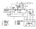
図1はこの発明の実施の形態1の可変吐出量燃料供給装置の燃料ポンプと電磁弁との動作タイミングを説明する動作説明図、図2は可変吐出量燃料供給装置の構成を示す系統図、図3は燃料ポンプの断面図である。図2において、1aないし1dは内燃機関の各気筒に設けられた燃料噴射弁、2は加圧された燃料を保持して燃料噴射弁1aないし1dに燃料を供給するデリバリパイプ、3はデリバリパイプ2に燃料経路10を介して加圧された燃料を供給する燃料ポンプ、4は燃料タンク5から燃料経路7を経由して燃料ポンプ3に燃料を供給する低圧燃料ポンプ、6は燃料経路7に設けられたエンジン停止時に燃圧経路7内の燃圧を一定時間保持するチェックバルブ、8は燃料経路7の圧力制御用の低圧レギュレータ、9はデリバリパイプ2の燃料圧が所定値を越えたときに燃料経路10から燃料経路11を介して燃料タンク5に燃料をリリーフするチェックバルブ、12は燃料ポンプ3から燃料タンク5に燃料を戻すリターン経路、13は燃料圧を制御する制御手段である。
【0014】
図3の燃料ポンプ3において、14はシリンダ、15は図示しないカムシャフトの駆動カムにローラ16を介して駆動され、シリンダ14内を往復動して加圧室17内に燃料を吸入し、加圧するプランジャ、18はプランジャ15を常時加圧室17が拡大する方向に付勢するバネ、19はローラ16を図示しないカムシャフト側に付勢するバネ、20はシリンダ14とプランジャ15との間から漏出する燃料をシールする金属製のベローズで、金属製のベローズ20内に漏出した燃料はリターン通路21と図2のリターン経路12とを介して燃料タンク5に戻される。22は低圧ダンパ23を有する燃料吸入口、24は図2の燃料経路10を介してデリバリパイプ2に接続される燃料吐出口であり、燃料吸入口22は燃料吸入通路25と例えばリードバルブなどの逆止弁にて構成される吸入弁26とを介して加圧室17に連通し、燃料吐出口24は吐出弁27を介して加圧室17に連通する。
【0015】
28は制御手段13からの開弁信号により開弁する常閉の電磁弁であり、弁体29と弁座30とからなる弁部は加圧室17から燃料吸入通路25に連通するリリーフ通路31を開閉するように設けられ、電磁弁28が開弁することにより加圧室17内の加圧された燃料がリリーフ通路31を経由して燃料吸入通路25にリリーフされるように構成されている。燃料ポンプ3は内燃機関に装着され、内燃機関のカムシャフトに設けられたポンプ駆動用のカムにより駆動され、内燃機関の回転に伴って燃料を加圧してデリバリパイプ2に圧送する。また、制御手段13には図示しないセンサ類から内燃機関の回転速度や、カムシャフトの回転角およびデリバリパイプ2の燃料圧などが入力され、電磁弁28に開弁信号を与えるように構成されている。
【0016】
このように構成されたこの発明の実施の形態1の可変吐出量燃料供給装置において、まず、内燃機関のキースイッチがオンされると電動の低圧燃料ポンプ4が作動して燃料タンク5より燃料ポンプ3に燃料が供給される。続いて内燃機関の始動操作と共に燃料ポンプ3が駆動され、プランジャ15の吸入行程では吐出弁27が閉じて吸入弁26が開き、燃料が燃料吸入口22と燃料吸入通路25とを介して加圧室17内に吸入され、プランジャ15の吐出行程では吸入弁26が閉じて吐出弁27が開き、加圧された燃料が燃料吐出口24から燃料経路10を通ってデリバリパイプ2に圧送される。また、エンジン停止時に燃料ポンプ3内の燃料圧は低下するが、デリバリパイプ2内の燃料圧は燃圧保持バルブ32が閉じることにより一定時間保持される。
【0017】
プランジャ15の往復動は内燃機関の回転速度と共に高くなり、デリバリパイプ2内の燃料圧が所定値に達すると制御手段13がこれを検知して電磁弁28に開弁信号を与え、弁を開いて高燃料圧の加圧室17を低燃料圧の燃料吸入通路25に連通させ、燃料をリリーフすることにより加圧室17からデリバリパイプ2に対する燃料の圧送を停止し、デリバリパイプ2内の燃料圧を一定値に保つ。このときの制御手段13の制御動作は次のように行われる。
【0018】
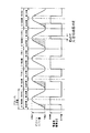
図1はこの制御動作の内容を示すもので、制御手段13からの開弁信号は図1に示すように、開弁信号の印可はデリバリパイプ2の燃料圧の検出値により決定されるが、終了位置はプランジャ15が上死点位置を経過した後の所定の位置とされる。図1の各行程AないしDはそれぞれ特徴のある行程を抽出して示したものであり、まず、行程Aはデリバリパイプ2内の燃料圧がプランジャ15の全ストロークの50%を吐出することによりデリバリパイプ2内の燃料圧が所定圧に達した場合を示し、この場合には、プランジャ15が下死点から上死点までのストロークの50%位置にて開弁信号が印加されて電磁弁28が開き、この開弁信号はプランジャ15の上死点過ぎの所定の位置まで継続される。プランジャの吐出期間は下死点から上死点までの間であるから、この場合の燃料リリーフ量は全ストロークの50%となる。
【0019】
また、行程Bはデリバリパイプ2内の燃料圧がプランジャ15の全ストロークの75%を吐出することにより、デリバリパイプ2内の燃料圧が所定圧に達した場合を示し、プランジャ15が下死点から上死点までのストロークの75%位置にて開弁信号が印可され、この開弁信号は行程Aの場合と同様にプランジャ15の上死点過ぎの所定の位置まで継続される。行程Cはデリバリパイプ2の燃料圧が所定値を満足しており、吐出量が0%でよいと判定された場合を示し、プランジャ15が下死点位置にて開弁信号が印可され、この開弁信号は行程Aおよび行程Bの場合と同様にプランジャ15の上死点過ぎの所定の位置まで継続される。
【0020】
行程Dはデリバリパイプ2内の燃料圧が低く、また燃料消費量が多い場合のように、吐出量が100%必要な状態を示し、この場合には圧力制御のためのリリーフは必要でないのでプランジャ15の上死点、または、上死点を誤差吸収分過ぎた位置にて開弁信号が印可され、行程Aないし行程Cの場合と同様にプランジャ15の上死点過ぎの所定の位置まで継続される。そして、この開弁信号の終了時点、すなわち、上死点過ぎの所定の位置は、例えば上死点から下死点までのストロークに対して所定の率で決定されるか、または、図1の行程Dに示すように電磁弁28の応答性のバラツキと制御ユニット13の制御のバラツキを補償し得る最小時間以上に設定される。
【0021】
制御動作を以上のように設定することにより、開弁信号幅を常に電磁弁28の応答性に必要なパルス幅以上に設定できることになり、また、制御のバラツキがあってもプランジャ15が上死点を過ぎた後に閉弁動作することになるので内燃機関の全回転域において安定した吐出量制御が可能になり、また、応答性の悪い電磁弁でも使用することが可能になる。さらに、電磁弁の応答性により限界があった内燃機関の回転速度のより高い領域までの制御ができることになると共に、電磁弁28のコイルには従来のような100%通電がなく、温度上昇を抑制して応答性の向上を可能とすることができる。
【0022】
【発明の効果】
以上に説明したようにこの発明の可変吐出量燃料供給装置によれば、電磁弁による加圧燃料のリリーフ量に関わらず、電磁弁の開弁時間を燃料ポンプのプランジャが上死点を過ぎた後、所定の一定位置まで継続されるようにし、この位置を電磁弁の応答性や制御のバラツキを加味して決定するようにしたので、燃料圧が安定して制御できると共に、電磁弁のコイルの温度上昇が抑制できて余裕のある設計が可能になり、また、より高速域までの制御に対応できて内燃機関の高速回転化を可能にする他、制御ユニットの制御精度や電磁弁の応答性を必要以上に向上させる必要がなくなるなど、優れた可変吐出量燃料供給装置を得ることができるものである。
【図面の簡単な説明】
【図1】 この発明の実施の形態1の可変吐出量燃料供給装置の動作説明図である。
【図2】 この発明の実施の形態1の可変吐出量燃料供給装置の構成を示す系統図である。
【図3】 この発明の実施の形態1の可変吐出量燃料供給装置に使用する燃料ポンプの構成を示す断面図である。
【図4】 従来の可変吐出量燃料供給装置の動作説明図である。
【符号の説明】
1a、1b、1c、1d 燃料噴射弁、2 デリバリパイプ、
3 燃料ポンプ、4 低圧燃料ポンプ、5 燃料タンク、
6、9 チェックバルブ、8 低圧レギュレータ
10,11 燃料経路、13 制御手段、14 シリンダ、
15 プランジャ、17 加圧室、18,19 バネ、
20 ベローズ、22 燃料吸入口、24 燃料吐出口、
25 燃料吸入通路、26 吸入弁、27 吐出弁、28 電磁弁、
29 弁体、30 弁座、31 リリーフ通路、32 燃圧保持バルブ。[0001]
BACKGROUND OF THE INVENTION
The present invention relates to a variable discharge amount fuel supply device that is used in an internal combustion engine for a vehicle, particularly a direct-injection gasoline engine that requires high-pressure pressurized fuel, and that controls the amount of fuel supplied to a fuel injection valve. is there.
[0002]
[Prior art]
A variable discharge amount fuel supply device used in an internal combustion engine for an automobile includes a plurality of fuel injection valves that inject fuel into each cylinder of the internal combustion engine, a delivery pipe that supplies fuel to these fuel injection valves, and the delivery From a fuel pump that supplies pressurized fuel to the pipe, a low-pressure fuel pump that supplies fuel from the fuel tank to this fuel pump, and a control means that controls the fuel injection timing, injection amount, fuel pump discharge amount, etc. The fuel pump is driven by a cylinder and a driving cam provided on the camshaft of the internal combustion engine, reciprocates in the cylinder, and sucks fuel into the pressurized chamber in the suction stroke, and in the discharge stroke. Discharge from the pressurization chamber by relieving the pressurized fuel in the pressurization chamber to the low pressure side at a specified timing, and a plunger that pumps the fuel in the pressurization chamber to the delivery pipe Controls, and a electromagnetic valve for controlling the fuel pressure in the delivery pipe to a predetermined pressure.
[0003]
For example, as disclosed in Japanese Patent Application Laid-Open No. 11-200990, this solenoid valve is generally a normally closed solenoid valve that is closed when there is no control signal to the solenoid valve. The valve is opened in response to a valve opening signal from the means, and the pressurized fuel in the pressurizing chamber is relieved to the low pressure side. Also, the control means detects the fuel pressure in the delivery pipe and opens the valve by giving a valve opening signal to the solenoid valve according to the fluctuation of the fuel pressure. However, the fuel pressure in the delivery pipe rises in the fuel pump. Since it is a discharge stroke, a valve opening signal is given in the middle of the discharge stroke, and a signal width is formed so as to close when the discharge stroke ends.
[0004]
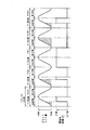
FIG. 4 is an explanatory diagram for explaining the stroke of the fuel pump and the operation timing of the solenoid valve used in such a conventional variable discharge amount fuel supply device, and is disclosed in, for example, Japanese Patent Application Laid-Open No. 11-200990. It is what. The piston lift shown in the figure indicates the amount of movement of the plunger that is reciprocated by being driven by the drive cam of the internal combustion engine. An amount of fuel is pressurized and pumped from the pressurized chamber to the delivery pipe, and the stroke from the top dead center to the bottom dead center is the suction stroke. In this suction stroke, the fuel is fed from the fuel tank into the pressurized chamber. Is introduced.
[0005]
The strokes A to D in the figure show the stroke of one cycle of the plunger of the fuel pump, respectively, and show the strokes with their characteristics extracted. The stroke of the conventional fuel pump and the operation of the solenoid valve will be described with reference to the drawings. First, the stroke A shows a case where only 50% of the discharge amount of the fuel pump is discharged, and 50% of the stroke in the discharge stroke of the plunger. The valve opening signal is given at the% position to open the solenoid valve, and the top dead center of the plunger, that is, the valve opening signal ends with the end of the discharge stroke, and the solenoid valve closes. Further, stroke B shows a case where a valve opening signal is given when the discharge amount is 75%, and the valve opening signal is terminated at the end of the discharge stroke in the same manner as stroke A.
[0006]
The stroke C indicates a case where the fuel pump discharge amount is large and the fuel consumption amount is small, such as when the engine brake is used at high speed and low load, and in this case, the fuel pressure in the delivery pipe is low. Is maintained at a predetermined value, the discharge amount from the fuel pump is 0%, the relief amount by the electromagnetic valve is 100%, and a valve opening signal is given over the entire stroke of the plunger. The stroke D is a case where the discharge amount of the fuel pump is small and the fuel consumption is large, for example, when the internal combustion engine is running at low speed and high load. In this case, a valve opening signal is given to make the discharge amount 100%. Absent.
[0007]
Of these strokes, when the discharge amount is 0% or 100%, it does not occur with high frequency. In normal use, the valve opening signal can be applied during the pressurization stroke of the plunger. Will end at top dead center. Since the signal width of the valve opening signal is determined by the fuel pressure in the delivery pipe, it always fluctuates depending on the engine speed and load conditions, and even when the engine speed and load are constant, each plunger stroke The control means calculates the valve opening timing and the valve opening signal width for each stroke, and gives them to the electromagnetic valve.
[0008]
[Problems to be solved by the invention]
In the conventional variable discharge amount fuel supply device, the valve opening signal as described above is given to the solenoid valve. However, when the fuel pressure of the delivery pipe rises to a predetermined pressure, such as immediately after starting the internal combustion engine, the discharge of the fuel pump When the fuel consumption is relatively large with respect to the amount, the fuel pressure may reach a predetermined value for a very short time just before the plunger passes top dead center. The valve signal is a short-time pulse signal. On the other hand, since the responsiveness of the solenoid valve to the valve opening signal is limited, the solenoid valve cannot follow the short-time pulse signal, and the control becomes impossible and the fuel pressure in the delivery pipe becomes unstable. There was a state. In particular, when the internal combustion engine rotates at high speed, the stroke time of the plunger is shortened and the signal width of the valve opening signal is also shortened. Therefore, the responsiveness of the solenoid valve limits the maximum rotational speed of the fuel pump.
[0009]
In addition, since the control unit also has control variations, in the above conventional control content, the valve may close during the discharge stroke before the top dead center of the plunger, and the delivery pipe is discharged again by the fuel pump. There is a problem that the internal fuel pressure becomes higher than a predetermined value. Further, when the engine brake of an internal combustion engine is used, the fuel consumption is small relative to the discharge amount of the fuel pump, and 0% of the discharge amount may continue. In such a case, the solenoid valve The current to the coil is 100%. Since the solenoid valve sets the coil resistance to be small in order to improve the responsiveness, there arises a problem that the coil temperature rises abnormally. In order to suppress this temperature rise, it is necessary to increase the coil resistance of the solenoid valve, which has the problem of further deteriorating the responsiveness of the solenoid valve.
[0010]
The present invention has been made to solve such a problem, and is capable of always stably controlling the fuel pressure without being affected by the responsiveness of the solenoid valve and variations in control, and the coil temperature is abnormal. An object of the present invention is to obtain a variable discharge amount fuel supply device that does not rise.
[0011]
[Means for Solving the Problems]
A variable discharge fuel supply device according to the present invention includes a fuel injection valve that injects fuel into each cylinder of an internal combustion engine, a delivery pipe that supplies pressurized fuel to these fuel injection valves, and a plunger that reciprocates in the cylinder. A fuel pump that sucks and pressurizes fuel from the fuel suction passage through the suction valve into the pressurization chamber, and discharges the pressurized fuel to the delivery pipe through the discharge valve, and a pressurization chamber of the fuel pump An electromagnetic valve for controlling the amount of pressurized fuel delivered to the delivery pipe by relieving the pressurized fuel in the pressurized chamber to the fuel suction passage when the valve is opened. Control means for giving a valve opening signal to the solenoid valve, and the valve opening signal given from the control means to the solenoid valve is from the top dead center of the plunger to the bottom dead center regardless of the relief amount of the pressurized fuel by the solenoid valve. Head for It is obtained by configured to terminate at a predetermined fixed position after a lapse of the top dead center during the entry stroke.
[0012]
In addition, the valve opening signal is configured to end after at least the response time of the electromagnetic valve has elapsed since the plunger passed through the top dead center.
[0013]
DETAILED DESCRIPTION OF THE INVENTION
FIG. 1 is an operation explanatory view for explaining the operation timing of a fuel pump and a solenoid valve of a variable discharge amount fuel supply apparatus according to
[0014]
In the
[0015]
[0016]
In the variable discharge amount fuel supply apparatus according to the first embodiment of the present invention configured as described above, first, when the key switch of the internal combustion engine is turned on, the electric low-
[0017]
The reciprocating motion of the
[0018]
FIG. 1 shows the contents of this control operation. The valve opening signal from the control means 13 is determined by the detected value of the fuel pressure of the delivery pipe 2 as shown in FIG. The end position is a predetermined position after the
[0019]
The stroke B shows a case where the fuel pressure in the delivery pipe 2 reaches 75% by discharging 75% of the total stroke of the
[0020]
The stroke D indicates a state in which the discharge amount is required to be 100% as in the case where the fuel pressure in the delivery pipe 2 is low and the fuel consumption is large. In this case, a relief for pressure control is not necessary. The valve opening signal is applied at 15 top dead center or at a position where the top dead center has exceeded the amount of error absorption, and continues to a predetermined position after the top dead center of the
[0021]
By setting the control operation as described above, the valve opening signal width can always be set to be greater than or equal to the pulse width necessary for the responsiveness of the
[0022]
【The invention's effect】
As described above, according to the variable discharge amount fuel supply device of the present invention, the plunger of the fuel pump has passed the top dead center regardless of the relief time of the pressurized fuel by the solenoid valve. After that, it is continued to a predetermined fixed position, and this position is determined in consideration of the response of the solenoid valve and the variation in control, so that the fuel pressure can be controlled stably and the coil of the solenoid valve In addition to being able to control the temperature rise of the engine, it is possible to design with sufficient margins, and to handle the control up to a higher speed range, enabling high-speed rotation of the internal combustion engine, control accuracy of the control unit and response of the solenoid valve Thus, it is possible to obtain an excellent variable discharge amount fuel supply device such that it is not necessary to improve the performance more than necessary.
[Brief description of the drawings]
FIG. 1 is an operation explanatory diagram of a variable discharge amount fuel supply device according to a first embodiment of the present invention.
FIG. 2 is a system diagram showing a configuration of a variable discharge amount fuel supply apparatus according to
FIG. 3 is a cross-sectional view showing a configuration of a fuel pump used in the variable discharge amount fuel supply apparatus according to
FIG. 4 is an operation explanatory diagram of a conventional variable discharge amount fuel supply device.
[Explanation of symbols]
1a, 1b, 1c, 1d fuel injection valve, 2 delivery pipe,
3 Fuel pump, 4 Low pressure fuel pump, 5 Fuel tank,
6, 9 Check valve, 8
15 Plunger, 17 Pressurizing chamber, 18, 19 Spring,
20 bellows, 22 fuel inlet, 24 fuel outlet,
25 fuel intake passage, 26 intake valve, 27 discharge valve, 28 solenoid valve,
29 Valve body, 30 Valve seat, 31 Relief passage, 32 Fuel pressure retention valve.
Claims (2)
Priority Applications (4)
| Application Number | Priority Date | Filing Date | Title |
|---|---|---|---|
| JP2000055335A JP3842002B2 (en) | 2000-03-01 | 2000-03-01 | Variable discharge fuel supply system |
| US09/613,716 US6343588B1 (en) | 2000-03-01 | 2000-07-11 | Variable delivery fuel supply device |
| DE10038646A DE10038646A1 (en) | 2000-03-01 | 2000-08-08 | Variable fuel supply device |
| FR0010521A FR2805861B1 (en) | 2000-03-01 | 2000-08-10 | VARIABLE FLOW FUEL SUPPLY DEVICE |
Applications Claiming Priority (1)
| Application Number | Priority Date | Filing Date | Title |
|---|---|---|---|
| JP2000055335A JP3842002B2 (en) | 2000-03-01 | 2000-03-01 | Variable discharge fuel supply system |
Publications (2)
| Publication Number | Publication Date |
|---|---|
| JP2001248515A JP2001248515A (en) | 2001-09-14 |
| JP3842002B2 true JP3842002B2 (en) | 2006-11-08 |
Family
ID=18576476
Family Applications (1)
| Application Number | Title | Priority Date | Filing Date |
|---|---|---|---|
| JP2000055335A Expired - Fee Related JP3842002B2 (en) | 2000-03-01 | 2000-03-01 | Variable discharge fuel supply system |
Country Status (4)
| Country | Link |
|---|---|
| US (1) | US6343588B1 (en) |
| JP (1) | JP3842002B2 (en) |
| DE (1) | DE10038646A1 (en) |
| FR (1) | FR2805861B1 (en) |
Families Citing this family (17)
| Publication number | Priority date | Publication date | Assignee | Title |
|---|---|---|---|---|
| JP3630407B2 (en) * | 2000-08-31 | 2005-03-16 | 三菱電機株式会社 | High pressure fuel supply device |
| ITTO20001227A1 (en) | 2000-12-29 | 2002-06-29 | Fiat Ricerche | COMMON MANIFOLD INJECTION SYSTEM FOR AN INTERNAL COMBUSTION ENGINE, WITH A FUEL PRE-DOSING DEVICE. |
| ITTO20001228A1 (en) * | 2000-12-29 | 2002-06-29 | Fiat Ricerche | FUEL INJECTION SYSTEM FOR AN INTERNAL COMBUSTION ENGINE. |
| GB0210753D0 (en) * | 2002-05-10 | 2002-06-19 | Delphi Tech Inc | Fuel pump |
| EP1873382B1 (en) * | 2002-06-20 | 2010-05-26 | Hitachi, Ltd. | Control device of high-pressure fuel pump of internal combustion engine |
| JP4101802B2 (en) | 2002-06-20 | 2008-06-18 | 株式会社日立製作所 | High pressure fuel pump control device for internal combustion engine |
| ITBO20040322A1 (en) * | 2004-05-20 | 2004-08-20 | Magneti Marelli Powertrain Spa | METHOD AND SYSTEM FOR DIRECT FUEL INJECTION INTO AN INTERNAL COMBUSTION ENGINE |
| ITBO20040323A1 (en) * | 2004-05-20 | 2004-08-20 | Magneti Marelli Powertrain Spa | METHOD OF DIRECT INJECTION OF FUEL INTO AN INTERNAL COMBUSTION ENGINE |
| EP1657430B1 (en) * | 2004-11-12 | 2008-05-07 | C.R.F. Società Consortile per Azioni | An accumulation volume fuel injection system for an internal combustion engine |
| DE102005014093A1 (en) * | 2005-03-29 | 2006-10-05 | Robert Bosch Gmbh | Two-step control of a high-pressure pump for direct injection gasoline engines |
| JP4672640B2 (en) * | 2006-11-30 | 2011-04-20 | 三菱重工業株式会社 | Engine fuel injection apparatus and operation method |
| DE602007009109D1 (en) * | 2007-09-21 | 2010-10-21 | Magneti Marelli Spa | Control method for a common-rail injection system with a shut-off valve for controlling the flow of a high-pressure fuel pump |
| ATE460582T1 (en) * | 2007-09-26 | 2010-03-15 | Magneti Marelli Spa | METHOD FOR CONTROLLING A COMMON RAIL DIRECT INJECTION SYSTEM WITH A HIGH PRESSURE FUEL PUMP |
| EP2241744A1 (en) * | 2009-04-15 | 2010-10-20 | Delphi Technologies Holding S.à.r.l. | Common Rail Fuel Pump and Control Method for a Common Rail Fuel Pump |
| EP2402584A1 (en) * | 2010-06-30 | 2012-01-04 | Hitachi Ltd. | Method and control apparatus for controlling a high-pressure fuel supply pump |
| US20130312706A1 (en) * | 2012-05-23 | 2013-11-28 | Christopher J. Salvador | Fuel system having flow-disruption reducer |
| WO2018081115A1 (en) * | 2016-10-24 | 2018-05-03 | Cummins Inc. | Fuel pump pressure control structure and methodology |
Family Cites Families (12)
| Publication number | Priority date | Publication date | Assignee | Title |
|---|---|---|---|---|
| DE3633107A1 (en) * | 1986-04-10 | 1987-10-15 | Bosch Gmbh Robert | FUEL INJECTION DEVICE FOR INTERNAL COMBUSTION ENGINES |
| EP0307947B1 (en) * | 1987-09-16 | 1993-11-18 | Nippondenso Co., Ltd. | Variable discharge high pressure pump |
| US5058553A (en) * | 1988-11-24 | 1991-10-22 | Nippondenso Co., Ltd. | Variable-discharge high pressure pump |
| EP0563760B2 (en) * | 1992-03-26 | 1999-05-12 | Zexel Corporation | Fuel-injection device |
| DE4407166C1 (en) * | 1994-03-04 | 1995-03-16 | Daimler Benz Ag | Fuel injection system for an internal combustion engine |
| JPH10176625A (en) | 1996-12-19 | 1998-06-30 | Unisia Jecs Corp | Plunger pump |
| JP3818607B2 (en) * | 1997-01-27 | 2006-09-06 | 株式会社小松製作所 | Control device and control method for cam-driven electronic control unit injector |
| JP3999855B2 (en) * | 1997-09-25 | 2007-10-31 | 三菱電機株式会社 | Fuel supply device |
| JP3471587B2 (en) * | 1997-10-27 | 2003-12-02 | 三菱電機株式会社 | High pressure fuel pump for in-cylinder injection |
| JPH11200990A (en) | 1998-01-07 | 1999-07-27 | Unisia Jecs Corp | Fuel injection control device |
| JP2000055335A (en) | 1998-08-13 | 2000-02-22 | Nittetu Chemical Engineering Ltd | Waste liquid treatment method |
| JP2000345901A (en) * | 1999-05-31 | 2000-12-12 | Isuzu Motors Ltd | Electronic fuel injection device |
-
2000
- 2000-03-01 JP JP2000055335A patent/JP3842002B2/en not_active Expired - Fee Related
- 2000-07-11 US US09/613,716 patent/US6343588B1/en not_active Expired - Fee Related
- 2000-08-08 DE DE10038646A patent/DE10038646A1/en not_active Ceased
- 2000-08-10 FR FR0010521A patent/FR2805861B1/en not_active Expired - Fee Related
Also Published As
| Publication number | Publication date |
|---|---|
| US6343588B1 (en) | 2002-02-05 |
| JP2001248515A (en) | 2001-09-14 |
| FR2805861B1 (en) | 2006-02-03 |
| DE10038646A1 (en) | 2001-09-27 |
| FR2805861A1 (en) | 2001-09-07 |
Similar Documents
| Publication | Publication Date | Title |
|---|---|---|
| JP3842002B2 (en) | Variable discharge fuel supply system | |
| US7757667B2 (en) | Control device of high-pressure fuel pump of internal combustion engine | |
| KR100373616B1 (en) | High-pressure fuel pump and cam for high-pressure fuel pump | |
| US7552720B2 (en) | Fuel pump control for a direct injection internal combustion engine | |
| JP4442048B2 (en) | High pressure fuel supply device for internal combustion engine | |
| JP2001248517A (en) | Variable discharge fuel supply device | |
| JP2002115623A (en) | Variable discharge-amount fuel supply device | |
| US7198034B2 (en) | Method and system for the direct injection of fuel into an internal combustion engine | |
| US9062625B2 (en) | Fuel control system and fuel control method of a gasoline direct injection engine | |
| JP3819208B2 (en) | Variable discharge fuel supply system | |
| US6959694B2 (en) | Fuel injection system for an internal combustion engine | |
| US7063073B2 (en) | Method for the direct injection of fuel into an internal combustion engine | |
| JP2004156574A (en) | Fluid loss/oil pressure fluctuation reducing structure for common rail (cr) fuel injection system | |
| JPH1077892A (en) | Accumulator fuel system for vehicle | |
| JP2006017111A (en) | Device for adjusting pressure/flow in internal combustion engine fuel injection device | |
| JP2639036B2 (en) | Variable discharge high pressure pump | |
| WO2001007779A1 (en) | High-pressure fuel pump and fuel feed method | |
| JPS5951156A (en) | Fuel injection device of internal-combustion engine | |
| JP4296732B2 (en) | In-cylinder injection internal combustion engine start-up control device | |
| EP1873382B1 (en) | Control device of high-pressure fuel pump of internal combustion engine | |
| JP4404056B2 (en) | Fuel injection device for internal combustion engine | |
| JP4389417B2 (en) | Fuel supply apparatus for in-cylinder injection internal combustion engine | |
| JPH088277Y2 (en) | Electronically controlled fuel injection device | |
| JPH10141176A (en) | Variable displacement high-pressure pump and fuel injector using the same | |
| JP2007162642A (en) | High pressure fuel pump for internal combustion engine |
Legal Events
| Date | Code | Title | Description |
|---|---|---|---|
| A131 | Notification of reasons for refusal |
Free format text: JAPANESE INTERMEDIATE CODE: A131 Effective date: 20051227 |
|
| A521 | Written amendment |
Free format text: JAPANESE INTERMEDIATE CODE: A523 Effective date: 20060221 |
|
| A131 | Notification of reasons for refusal |
Free format text: JAPANESE INTERMEDIATE CODE: A131 Effective date: 20060418 |
|
| A521 | Written amendment |
Free format text: JAPANESE INTERMEDIATE CODE: A523 Effective date: 20060529 |
|
| TRDD | Decision of grant or rejection written | ||
| A01 | Written decision to grant a patent or to grant a registration (utility model) |
Free format text: JAPANESE INTERMEDIATE CODE: A01 Effective date: 20060801 |
|
| A61 | First payment of annual fees (during grant procedure) |
Free format text: JAPANESE INTERMEDIATE CODE: A61 Effective date: 20060809 |
|
| FPAY | Renewal fee payment (event date is renewal date of database) |
Free format text: PAYMENT UNTIL: 20090818 Year of fee payment: 3 |
|
| FPAY | Renewal fee payment (event date is renewal date of database) |
Free format text: PAYMENT UNTIL: 20100818 Year of fee payment: 4 |
|
| FPAY | Renewal fee payment (event date is renewal date of database) |
Free format text: PAYMENT UNTIL: 20110818 Year of fee payment: 5 |
|
| FPAY | Renewal fee payment (event date is renewal date of database) |
Free format text: PAYMENT UNTIL: 20110818 Year of fee payment: 5 |
|
| FPAY | Renewal fee payment (event date is renewal date of database) |
Free format text: PAYMENT UNTIL: 20120818 Year of fee payment: 6 |
|
| FPAY | Renewal fee payment (event date is renewal date of database) |
Free format text: PAYMENT UNTIL: 20120818 Year of fee payment: 6 |
|
| FPAY | Renewal fee payment (event date is renewal date of database) |
Free format text: PAYMENT UNTIL: 20130818 Year of fee payment: 7 |
|
| LAPS | Cancellation because of no payment of annual fees |