JP3841664B2 - shutter - Google Patents
shutter Download PDFInfo
- Publication number
- JP3841664B2 JP3841664B2 JP2001324372A JP2001324372A JP3841664B2 JP 3841664 B2 JP3841664 B2 JP 3841664B2 JP 2001324372 A JP2001324372 A JP 2001324372A JP 2001324372 A JP2001324372 A JP 2001324372A JP 3841664 B2 JP3841664 B2 JP 3841664B2
- Authority
- JP
- Japan
- Prior art keywords
- shutter
- guide rail
- locking
- bar member
- vertical frame
- Prior art date
- Legal status (The legal status is an assumption and is not a legal conclusion. Google has not performed a legal analysis and makes no representation as to the accuracy of the status listed.)
- Expired - Lifetime
Links
Images


Description
【0001】
【発明の属する技術分野】
本発明は、シャッターに係り、特に錠バー部材の係止受部の構造を改良して防犯性の向上を図ったシャッターに関する。
【0002】
【従来の技術】
建物の開口に設けられるシャッターにおいては、左右の縦枠と、これら縦枠の上方に設けられシャッター板(シャッターカーテンともいう)を巻取り収納するシャッターボックスと、前記縦枠の室外側に設けられシャッター板の側部を案内するガイドレールと、前記シャッター板を閉鎖位置に固定する錠機構とを備えて構成されている。
【0003】
前記錠機構は施錠操作により側方へ突出する錠バー部材を有しており、前記ガイドレールの奥部には前記錠バー部材を係止するためのラッチ受けが設けられていた。
【0004】
【発明が解決しようとする課題】
しかしながら、前記シャッターにおいては、防犯性を考えた場合、ガイドレールの奥部に設けられているラッチ受けがガイドレールを外部からドライバー等でこじ開ける(ガイド溝の側片を無理矢理室外側に開き曲げる)と露出してしまうため、ラッチ受けに対する錠バー部材の係止状態を不正に解除(解錠)される恐れがあり、防犯性の点で十分とはいえなかった。
【0005】
本発明は、前記事情を考慮してなされたもので、錠バー部材の係止状態を不正に解除され難くして防犯性の向上を図ったシャッターを提供することを目的とする。
【0006】
【課題を解決するための手段】
本発明は、物の開口に設けられるシャッターであって、左右の縦枠と、該縦枠の上方に設けられシャッター板を巻取り収納するシャッターボックスと、前記縦枠の室外側に設けられシャッター板の側部を案内するガイドレールと、前記シャッター板を閉鎖位置に固定する錠機構とを備え、前記錠機構は施錠操作によりシャッター板の側部から側方へ突出する錠バー部材を有し、前記ガイドレールは奥部に仕切壁を介して中空部を有し、前記錠機構の施錠時に側方へ突出する錠バー部材を前記中空部に挿入して係止するために、前記仕切壁に縦長の開口部を設けると共に、該開口部に係止孔が設けられた裏板を取付けたことを特徴とする。
【0007】
【発明の実施の形態】
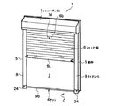
以下に、本発明の実施の形態を添付図面に基いて詳述する。図1は本発明の実施の形態を示すシャッターの概略的斜視図、図2は同シャッターの縦断面図、図3は同シャッターの横断面図、図4は土間仕上げ調整部品を示す図で、(a)は斜視図、(b)は平面図、図5は縦枠を示す図で、(a)は平面図、(b)は内側面図である。
【0008】
これらの図において、1は店舗等に使用される土間用のシャッターで、建物の躯体2の開口3に設けたサッシ4の室外側に一体または別体で設けられる(図示例は一体の場合を示している。)。このシャッター1は、シャッター枠を構成する左右の縦枠5,5と、該縦枠5,5の上方に設けられシャッター板6を巻取り収納するシャッターボックス7と、前記縦枠5の室外側に着脱自在に設けられシャッター板6の側部を案内するガイドレール8とを備えている。
【0009】
前記サッシ4は、例えばアルミ押出形材からなる上枠9a、下枠9bおよび左右の縦枠6c,9cからなるサッシ枠9内に内外の障子10a,10bを引違い状に開閉自在に取付けた引違いサッシからなっている。本実施の形態の図示例では、図2に示すように、サッシ枠9の縦枠9cとシャッター枠の縦枠5とが一体になっているが、別体になっていても良い。
【0010】
なお、前記シャッター枠は、例えばアルミ押出形材からなる左右の縦枠5,5と、両縦枠5,5の上端部間に掛け渡されて組付けられる上枠(シャッター上枠)11とを備え、両縦枠5,5の中間部間にはサッシ4の上枠9aが一体化された中間枠(シャッター中間枠)12が掛け渡されて組付けられていると共に、両縦枠5,5の下端部間にサッシ4の下枠9bが掛け渡されて組付けられている。
【0011】
前記シャッターボックス7は、シャッター枠における上枠11と中間枠12の間に設けられている。シャッターボックス7内には、シャッター板6を巻き上げ巻き下げする巻取ドラム13が設けられている。シャッタ板6は、水平に細長い金属板からなるスラットを縦方向に鎧状につないでなり、シャッター板6の先端部(下端部)にはエンドスラット6aが設けられ、高さ方向略中間のスラット6bにはシャッター板6を閉鎖位置に固定するための後述の錠機構14が設けられている。前記スラット6a,6bは、強度上例えばアルミ押出形材からなる幅木からなっていることが好ましく、スラット6bの裏側(室内側)に錠機構14が設けられている。なお、シャッター1は、手動式でも、電動式でも良い。
【0012】
縦枠5は、図3ないし図5に示すように中空部16a,16bを有するホロー構造とされており、その室外端には外側面の延長上に断面L字状の係合受部17が形成されていると共に内側にリブ受部18が形成されている。ガイドレール8は、例えばアルミ押出形材からなり、内側に開口した断面コ字状のガイド溝8aを有していると共にこのガイド溝8aに隣接して中空部8bを有するホロー構造とされている。換言すれば、ガイドレール8はガイド溝8aの奥部に仕切壁8cを介して中空部8bを有している。このガイドレール8の室内端には、外側面の延長上に前記縦枠5の係合受部17に係合される断面略コ字状の係合部19が形成されていると共に、前記縦枠5のリブ受部18に当接されて固着具例えばネジ20で固定されるリブ21が形成されている。
【0013】
前記ガイドレール8は、予め工場で所定の高さ寸法に切断加工されている。縦枠5に対するガイドレール8の取付時にガイドレール8が下方へズレ落ちないように縦枠5の下端から所定高さhaの位置にガイドレール8の下端を位置決め係止するために、図5に示すように縦枠5の断面L字状の係合受部17にはガイドレール8の係合部19下端を係止する係止部22が曲げ加工により設けられており、縦枠5に対してガイドレール8を一人作業でも容易に且つ正確に取付けることができるようになっている。
【0014】
ガイドレール8の現場加工を不要にして施工性の向上を図ると共に、土間仕上げ後のガイドレール8の脱着を可能にしてメンテナンス性の向上を図るために、前記ガイドレール8の下端部には、土間仕上げ用コンクリートまたはモルタル23にその一部が埋設される土間仕上げ調整部品24が着脱自在に設けられている。この土間仕上げ調整部品24は、例えば合成樹脂により形成されている。
【0015】
土間仕上げ調整部品24は、図1〜図3,図4に示すように、下端から所定の高さの位置hbに水平に形成されガイドレール8の下端面を当接させる当接面部(上面部)25と、該当接面25から下方に向ってガイドレール8のガイド溝8aと略同じ断面でガイド溝8と連続するように形成された補助ガイド溝部26と、ガイドレール8の下側の正面部および外側面部を覆うと共にこれらの位置を規制すべく断面L字状で上方に立上がった立上り部27とを有している。
【0016】
前記補助ガイド溝部26の下端は、土間仕上げ調整部品24の下端まで達していても良いが、図示例のように土間仕上げ調整部品24の下端から所定の高さhc位置とされていることが好ましい。前記当接面部25には、ガイド溝8aの中空部8bに嵌挿される位置決め突部28が突設されている。土間仕上げ調整部品24は、ガイドレール8の下端部に固着具例えばネジ29で着脱自在に固定されている。前記立上り部27の正面側には、ネジ29を挿通する挿通穴(孔部)30が設けられており、この挿通穴30からガイドレール8の下端正面部にネジ29がねじ込まれるようになっている。
【0017】
土間仕上げ調整部品24は、現場でガイドレール8の下端部に取付けても良いが、予め工場でガイドレール8の下端部に取付けられていることが、現場での施工を簡略化ないし省略化する上で好ましい。躯体2へのシャッター1の取付け後に土間(地面)Gには、コンクリートまたはモルタル23が打設されて土間仕上げが施される。この場合、縦枠(サッシの縦枠を含む)5の下端部およびサッシ4の下枠9bの下部と共に土間仕上げ調整部品24の下部がコンクリートまたはモルタル23中に埋め込まれる。土間仕上げ調整部品24があることにより、ガイドレール8の下端部はコンクリートまたはモルタル23中に埋め込まれることはなく、施工後にネジ29を緩める(取外す)ことにより縦枠5および土間仕上げ調整部品24からガイドレール8を取外すことが可能(脱着可能)となり、メンテナンスが可能となる。
【0018】
土間仕上げ調整部品24には、土間仕上げの上限31を示す上限ライン32および下限33を示す下限ライン34が表示されていることが好ましい。土間仕上げの上限31はサッシ4の下枠9bの略上面位置とされ、土間仕上げの下限33は土間仕上げ調整部品24の補助ガイド溝部26の下端位置とされている。土間仕上げの下限33が補助ガイド溝部26の下端位置よりも下方にあると、閉鎖状態のシャッター板6の下端と土間仕上げ面15との間に隙間が発生してしまうからである。なお、図2の点線は土間仕上げ面15の標準位置を示している。土間仕上げ調整部品24の下端部にはコンクリートまたはモルタル23内からの引き抜けを防止するための抵抗となる鍔部24aが設けられていることが好ましい。
【0019】
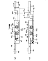
図6は錠機構を概略的に示す図で、(a)は施錠時の状態図、(b)は解錠時の状態図、図7はガイドレールにおける錠バー部材の係止孔を示す部分的切断斜視図、図8はガイドレールにおける錠バー部材の係止孔を示す図で、(a)は横断面図、(b)は縦断面図である。前記錠機構14は、室内外方向の厚さが薄く横長で左右両端が開口したケーシング40を有し、このケーシング40内には室外側から鍵を挿入して回転操作する鍵穴41を有する操作歯車(第1の歯車)42と、この操作歯車42に噛合して左右方向に移動操作される第1のラック43aを有する操作バー部材43と、その第1のラック43aに噛合して回転操作される伝達歯車(第2の歯車)44と、この伝達歯車44と同軸上に一体的に設けられた作動歯車(第3の歯車)45と、この作動歯車45の上部と下部に噛合して左右方向に対称的に移動操作される第2のラック46aを有する2本の作動バー部材46,46とが設けられている。
【0020】
前記操作バー部材43の一端にはこれを室内側から手動操作するための操作摘み43bが設けられている。操作バー部材43の他端とケーシング40との間には操作バー部材43をストロークエンドに付勢するためのバネ47が設けられている。前記作動歯車45は、操作摘み43aの操作ストロークSaと作動バー部材46の作動ストロークSbに差を持たせるために、図示例では伝達歯車44の歯数よりも少ない歯数例えば4つの歯を有するものからなっているが、これに限定されるものではない。各作動バー部材46の一端には錠バー部材48が連結されており、前記錠機構14は鍵の操作もしくは操作摘み43bの操作により錠バー部材48がシャッター板6の両側部(スラット6bの両端部)から側方に突出し(施錠時)あるいは引っ込む(解錠時)ように構成されている。
【0021】
ガイドレール8の仕切壁8cには、前記錠機構14の施錠時に側方へ突出する錠バー部材48を前記中空部8bに挿入して係止するための係止孔49が設けられている。この場合、係止孔49は土間仕上げ面15に応じて変化する錠バー部材48の高さ位置に対応し得るように高さ方向に所定ピッチで複数例えば図示例では3つ設けられていることが好ましい。この場合、係止孔49の加工性を考慮して、仕切壁8cには複数の係止孔49を包含する縦長の1つの開口部50を設け、仕切壁8cの裏側にはその開口部50に臨んで開口する複数例えば3つの係止孔49を設けた裏板51を取付けることが好ましい。ガイドレール8の内側面には裏板51を仕切壁8cの裏面に位置するように中空部8bに挿入する挿入口52が設けられ、裏板51の一側部にはガイドレール8の内側面に当接されて室内側から固着具例えばネジもしくはリベット53で取付固定される取付片51aが直角に形成されている。
【0022】
次に、以上の構成からなるシャッター1の取付け施工方法および作用について説明する。先ず、シャッター枠、サッシ4の下枠9bおよびシャッターボックス7の組付けを行い、これを躯体2に取付固定する。次に、シャッター枠の縦枠5にガイドレール8を取付ける。ガイドレール8には、予め工場または現場で土間仕上げ調整部品24が取付けられている。
【0023】
次に、土間にコンクリートまたはモルタル23を打設し、コンクリートまたはモルタル23中に縦枠5の下端部、サッシ4の下枠9bの下部および土間仕上げ調整部品24の下部を埋め込み、土間仕上げを行えば良く、これによりシャッター1および土間仕上げの施工が完了する。施工後は、ネジ29を緩めることにより縦枠5および土間仕上げ調整部品24からガイドレール8を取外すことが可能(脱着可能)となり、ガイドレール8やシャッター板6等のメンテナンスを容易に行うことができる。
【0024】
以上の構成からなるシャッター1によれば、建物の開口3に設けたサッシ4の室外側に一体または別体で設けられ設けられるシャッターであって、左右の縦枠5,5と、該縦枠5,5の上方に設けられシャッター板6を巻取り収納するシャッターボックス7と、前記縦枠5,5の室外側に着脱自在に設けられシャッター板6の側部を案内するガイドレール8,8とを備え、前記ガイドレール8の下端部に土間仕上げ用コンクリートまたはモルタル23に埋設される土間仕上げ調整部品24を着脱自在に設けているため、土間仕上げ後にもガイドレール8の脱着が可能で施工後のメンテナンスが可能となると共に、ガイドレール8の現場加工が不要になり施工性の向上が図れる。
【0025】
また、縦枠5には、ガイドレール8の取付時にガイドレール8が下方へズレ落ちないように縦枠5の下端から所定高さhcの位置にガイドレール8の下端を位置決め係止するための係止部22が設けられているため、縦枠5に対してガイドレール8を一人作業でも容易に且つ正確に取付けることが可能となり、施工性の向上が図れる。
【0026】
特に、前記シャッター1によれば、前記シャッター板6を閉鎖位置に固定する錠機構14を備え、前記錠機構14は施錠操作によりシャッター板6の側部から側方へ突出する錠バー部材48を有し、前記ガイドレール8は奥部に仕切壁8cを介して中空部8bを有し、その仕切壁8cに前記錠機構14の施錠時に側方へ突出する錠バー部材48を前記中空部8bに挿入して係止するための係止孔49を設けているため、たとえガイドレール8がドライバー等で外部からこじ開けられ(ガイド溝8aの側片を無理矢理室外側に開き曲げられ)たとしても錠バー部材48の先端部が係止孔49から中空部8b内に挿入されていて露出することがない。従って、ドライバー等で錠バー部材48の先端部を中空部8b内から中空部8b外に(離脱方向へ)押出すことができず(離脱させることができず)、係止孔49に対する錠バー部材48の係止状態を不正に解除ないし解錠され難いため、防犯性を十分に確保することができる。
【0027】
また、前記係止孔49は土間仕上げ面15に応じて変化する錠バー部材の高さ位置に対応し得るように高さ方向に所定ピッチで複数例えば図示例では3つ設けられているため、シャッター板6が閉鎖位置で施錠されるように施錠位置を容易に調整することができ、施工性の向上が図れる。また、係止孔49の加工性を考慮して、仕切壁8cには複数の係止孔49を包含する縦長の1つの開口部50を設け、仕切壁8cの裏側にはその開口部50に臨んで開口する複数例えば3つの係止孔49を設けた裏板51を取付けているため、加工性の向上が図れる。また、前記裏板51の取付位置を調整することにより、施錠位置の微調整が容易にできる。この場合、裏板51を高さ方向(上下方向に)に微調整し得るように取付片に形成されている固着具挿通孔(ネジ孔)を長穴にすることが好ましい。
【0028】
以上、本発明の実施の形態を図面により詳述してきたが、本発明は前記実施の形態に限定されるものではなく、本発明の要旨を逸脱しない範囲での種々の設計変更等が可能である。例えば、シャッターは、サッシとは別体で設けられていても良い。また、シャッターは、土間用に限定されず、窓サッシの室外側に設けられるものであっても良い。本発明が適用されるシャッターは、必ずしもサッシを必要とするものではなく、シャッターが設けられる建物の開口にはサッシが設けられていなくても良い。
【0029】
【発明の効果】
以上要するに本発明によれば、物の開口に設けられるシャッターであって、左右の縦枠と、該縦枠の上方に設けられシャッター板を巻取り収納するシャッターボックスと、前記縦枠の室外側に設けられシャッター板の側部を案内するガイドレールと、前記シャッター板を閉鎖位置に固定する錠機構とを備え、前記錠機構は施錠操作によりシャッター板の側部から側方へ突出する錠バー部材を有し、前記ガイドレールは奥部に仕切壁を介して中空部を有し、前記錠機構の施錠時に側方へ突出する錠バー部材を前記中空部に挿入して係止するために、前記仕切壁に縦長の開口部を設けると共に、該開口部に係止孔が設けられた裏板を取付けたので、たといガイドレールがドライバー等で外部からこじ開けられたとしても錠バー部材の先端部が係止孔から中空部に挿入されていて露出しないため、錠バー部材の係止状態を不正に解除され難く、防犯性の向上が図れると共に、シャッター板が閉鎖位置で施錠されるように施錠位置を容易に調整することができる。
【図面の簡単な説明】
【図1】本発明の実施の形態を示すシャッターの概略的斜視図である。
【図2】同シャッターの縦断面図である。
【図3】同シャッターの横断面図である。
【図4】土間仕上げ調整部品を示す図で、(a)は斜視図、(b)は平面図である。
【図5】縦枠を示す図で、(a)は平面図、(b)は内側面図である。
【図6】錠機構を概略的に示す図で、(a)は施錠時の状態図、(b)は解錠時の状態図である。
【図7】ガイドレールにおける錠バー部材の係止孔を示す部分的切断斜視図である。
【図8】ガイドレールにおける錠バー部材の係止孔を示す図で、(a)は横断面図、(b)は縦断面図である。
【符号の説明】
1 シャッター
5 縦枠
6 シャッター板
7 シャッターボックス
8 ガイドレール
8b 中空部
8c 仕切壁
14 錠機構
48 錠バー部材
49 係止孔[0001]
BACKGROUND OF THE INVENTION
The present invention relates to a shutter, and more particularly, to a shutter that is improved in crime prevention by improving the structure of a lock receiving portion of a lock bar member.
[0002]
[Prior art]
In the shutter provided in the opening of the building, the left and right vertical frames, the shutter box provided above these vertical frames to wind up and store the shutter plate (also referred to as shutter curtain), and the outdoor side of the vertical frame are provided. A guide rail for guiding a side portion of the shutter plate and a lock mechanism for fixing the shutter plate in a closed position are provided.
[0003]
The lock mechanism has a lock bar member that protrudes to the side by a locking operation, and a latch receiver for locking the lock bar member is provided at the back of the guide rail.
[0004]
[Problems to be solved by the invention]
However, in the shutter, when security is considered, the latch receiver provided at the back of the guide rail prys the guide rail from the outside with a screwdriver or the like (forcibly opens and bends the side piece of the guide groove to the outside of the room). Therefore, the locked state of the lock bar member with respect to the latch receiver may be illegally released (unlocked), which is not sufficient in terms of crime prevention.
[0005]
The present invention has been made in view of the above circumstances, and an object of the present invention is to provide a shutter that is improved in crime prevention by preventing the locking state of the lock bar member from being illegally released.
[0006]
[Means for Solving the Problems]
The present invention relates to a shutter provided in an opening of an object, the left and right vertical frames, a shutter box provided above the vertical frame to wind up and store a shutter plate, and a shutter provided outside the vertical frame. A guide rail that guides the side of the plate, and a lock mechanism that fixes the shutter plate in a closed position, and the lock mechanism has a lock bar member that protrudes laterally from the side of the shutter plate by a locking operation. the guide rail has a hollow portion through the partition wall at the back portion, the lock bar member projecting laterally during locking of the front Kijo mechanism for locking is inserted into the hollow portion, the partition A vertically long opening is provided on the wall, and a back plate provided with a locking hole is attached to the opening .
[0007]
DETAILED DESCRIPTION OF THE INVENTION
Hereinafter, embodiments of the present invention will be described in detail with reference to the accompanying drawings. FIG. 1 is a schematic perspective view of a shutter showing an embodiment of the present invention, FIG. 2 is a longitudinal sectional view of the shutter, FIG. 3 is a transverse sectional view of the shutter, and FIG. (A) is a perspective view, (b) is a plan view, FIG. 5 is a view showing a vertical frame, (a) is a plan view, and (b) is an inner side view.
[0008]
In these drawings, reference numeral 1 denotes a dirt shutter used in a store or the like, which is provided integrally or separately on the outside of the sash 4 provided in the
[0009]
In the sash 4, for example, inner and
[0010]
The shutter frame includes left and right
[0011]
The shutter box 7 is provided between the
[0012]
As shown in FIGS. 3 to 5, the
[0013]
The
[0014]
In order to improve the workability by eliminating the on-site processing of the
[0015]
As shown in FIGS. 1 to 3 and 4, the earth finishing
[0016]
The lower end of the
[0017]
The earth finishing
[0018]
It is preferable that an
[0019]
6A and 6B are diagrams schematically showing the lock mechanism, where FIG. 6A is a state diagram at the time of locking, FIG. 6B is a state diagram at the time of unlocking, and FIG. 7 is a portion showing a locking hole of the lock bar member in the guide rail. FIG. 8 is a diagram showing a locking hole of the lock bar member in the guide rail, (a) is a transverse sectional view, and (b) is a longitudinal sectional view. The
[0020]
One end of the
[0021]
The
[0022]
Next, a mounting method and operation of the shutter 1 having the above configuration will be described. First, the shutter frame, the
[0023]
Next, concrete or
[0024]
According to the shutter 1 configured as described above, the shutter 1 is provided integrally or separately on the outdoor side of the sash 4 provided in the
[0025]
In addition, the
[0026]
In particular, the shutter 1 includes a
[0027]
In addition, since the plurality of the locking holes 49 are provided at a predetermined pitch in the height direction so as to be able to correspond to the height position of the lock bar member that changes in accordance with the
[0028]
Although the embodiments of the present invention have been described in detail with reference to the drawings, the present invention is not limited to the above-described embodiments, and various design changes and the like can be made without departing from the scope of the present invention. is there. For example, the shutter may be provided separately from the sash. In addition, the shutter is not limited to dirt, and may be provided outside the window sash. The shutter to which the present invention is applied does not necessarily require a sash, and a sash may not be provided in an opening of a building where the shutter is provided .
[0029]
【The invention's effect】
In summary, according to the present invention, a shutter is provided at an opening of an object, and includes a left and right vertical frame, a shutter box that is provided above the vertical frame and winds and stores a shutter plate, and an outdoor side of the vertical frame Provided with a guide rail for guiding the side of the shutter plate and a lock mechanism for fixing the shutter plate in a closed position, the lock mechanism protruding from the side of the shutter plate to the side by a locking operation. has a member, the guide rail has a hollow portion through the partition wall at the back portion, for locking the lock bar member projecting laterally during locking of the front Kijo mechanism is inserted into the hollow portion In addition, since the partition wall is provided with a vertically long opening and a back plate provided with a locking hole is attached to the opening, even if the guide rail is pry open from the outside with a screwdriver or the like, The tip is locked From order not exposed is inserted into the hollow portion, hardly released illegally locked state of the lock bar member, with can be improved crime prevention, easily locked position as the shutter plate is locked in the closed position Can be adjusted .
[Brief description of the drawings]
FIG. 1 is a schematic perspective view of a shutter showing an embodiment of the present invention.
FIG. 2 is a longitudinal sectional view of the shutter.
FIG. 3 is a cross-sectional view of the shutter.
FIGS. 4A and 4B are diagrams showing a chamfer finish adjusting part, where FIG. 4A is a perspective view and FIG. 4B is a plan view.
5A and 5B are diagrams showing a vertical frame, where FIG. 5A is a plan view and FIG. 5B is an inner side view.
6A and 6B are diagrams schematically showing a locking mechanism, where FIG. 6A is a state diagram at the time of locking, and FIG. 6B is a state diagram at the time of unlocking.
FIG. 7 is a partially cut perspective view showing a locking hole of a lock bar member in a guide rail.
8A and 8B are diagrams showing a locking hole of a lock bar member in a guide rail, wherein FIG. 8A is a transverse sectional view and FIG. 8B is a longitudinal sectional view.
[Explanation of symbols]
DESCRIPTION OF SYMBOLS 1
Claims (1)
Priority Applications (1)
| Application Number | Priority Date | Filing Date | Title |
|---|---|---|---|
| JP2001324372A JP3841664B2 (en) | 2001-10-23 | 2001-10-23 | shutter |
Applications Claiming Priority (1)
| Application Number | Priority Date | Filing Date | Title |
|---|---|---|---|
| JP2001324372A JP3841664B2 (en) | 2001-10-23 | 2001-10-23 | shutter |
Publications (2)
| Publication Number | Publication Date |
|---|---|
| JP2003129777A JP2003129777A (en) | 2003-05-08 |
| JP3841664B2 true JP3841664B2 (en) | 2006-11-01 |
Family
ID=19141106
Family Applications (1)
| Application Number | Title | Priority Date | Filing Date |
|---|---|---|---|
| JP2001324372A Expired - Lifetime JP3841664B2 (en) | 2001-10-23 | 2001-10-23 | shutter |
Country Status (1)
| Country | Link |
|---|---|
| JP (1) | JP3841664B2 (en) |
Families Citing this family (3)
| Publication number | Priority date | Publication date | Assignee | Title |
|---|---|---|---|---|
| JP2006063738A (en) * | 2004-08-30 | 2006-03-09 | Chuo Spring Co Ltd | Screen lifting device |
| JP4912025B2 (en) * | 2005-09-29 | 2012-04-04 | 文化シヤッター株式会社 | Opening and closing body device |
| JP7260423B2 (en) | 2019-07-03 | 2023-04-18 | 文化シヤッター株式会社 | Shutter device with locking device |
-
2001
- 2001-10-23 JP JP2001324372A patent/JP3841664B2/en not_active Expired - Lifetime
Also Published As
| Publication number | Publication date |
|---|---|
| JP2003129777A (en) | 2003-05-08 |
Similar Documents
| Publication | Publication Date | Title |
|---|---|---|
| US20080053623A1 (en) | Roller screen assemblies | |
| EP1703052A1 (en) | Interlocking mechanism for a window or the like | |
| US4226049A (en) | Security ventilating system | |
| US7793463B1 (en) | Plantation style security shutters | |
| JP3841664B2 (en) | shutter | |
| GB2190416A (en) | Closure assemblies | |
| EP0942141A2 (en) | Corner assembly for a frame | |
| KR200385577Y1 (en) | Safety window | |
| US20090242141A1 (en) | Mosquito curtain for rolling shutters or window openings | |
| US4485589A (en) | Controllable detention window | |
| US6170555B1 (en) | Corner assembly for a frame | |
| JP4920324B2 (en) | Sliding door sash | |
| JP3400695B2 (en) | Roll screen device | |
| EP2920396B1 (en) | A window comprising a screening arrangement with mounting means and method of providing a window with a screening arrangement | |
| JP2003106071A (en) | Dirt floor | |
| JP6749833B2 (en) | Joinery | |
| JP2018105103A (en) | Door sheave and fitting | |
| JP4572379B2 (en) | Face lattice | |
| JP4452151B2 (en) | Frame device | |
| JP4056873B2 (en) | Window shutter device | |
| JP6710631B2 (en) | Joinery | |
| KR102026443B1 (en) | Installation Structure of Lock Handle for Window | |
| JP4531192B2 (en) | Shutter locking device | |
| JP4439821B2 (en) | Opening structure | |
| JP6710632B2 (en) | Joinery |
Legal Events
| Date | Code | Title | Description |
|---|---|---|---|
| A621 | Written request for application examination |
Free format text: JAPANESE INTERMEDIATE CODE: A621 Effective date: 20040520 |
|
| A977 | Report on retrieval |
Free format text: JAPANESE INTERMEDIATE CODE: A971007 Effective date: 20060206 |
|
| A131 | Notification of reasons for refusal |
Free format text: JAPANESE INTERMEDIATE CODE: A131 Effective date: 20060411 |
|
| A521 | Written amendment |
Free format text: JAPANESE INTERMEDIATE CODE: A523 Effective date: 20060606 Free format text: JAPANESE INTERMEDIATE CODE: A821 Effective date: 20060606 |
|
| RD02 | Notification of acceptance of power of attorney |
Free format text: JAPANESE INTERMEDIATE CODE: A7422 Effective date: 20060606 |
|
| A521 | Written amendment |
Free format text: JAPANESE INTERMEDIATE CODE: A821 Effective date: 20060606 |
|
| TRDD | Decision of grant or rejection written | ||
| A01 | Written decision to grant a patent or to grant a registration (utility model) |
Free format text: JAPANESE INTERMEDIATE CODE: A01 Effective date: 20060725 |
|
| A61 | First payment of annual fees (during grant procedure) |
Free format text: JAPANESE INTERMEDIATE CODE: A61 Effective date: 20060808 |
|
| R150 | Certificate of patent or registration of utility model |
Ref document number: 3841664 Country of ref document: JP Free format text: JAPANESE INTERMEDIATE CODE: R150 Free format text: JAPANESE INTERMEDIATE CODE: R150 |
|
| FPAY | Renewal fee payment (event date is renewal date of database) |
Free format text: PAYMENT UNTIL: 20100818 Year of fee payment: 4 |
|
| FPAY | Renewal fee payment (event date is renewal date of database) |
Free format text: PAYMENT UNTIL: 20100818 Year of fee payment: 4 |
|
| FPAY | Renewal fee payment (event date is renewal date of database) |
Free format text: PAYMENT UNTIL: 20110818 Year of fee payment: 5 |
|
| S533 | Written request for registration of change of name |
Free format text: JAPANESE INTERMEDIATE CODE: R313533 |
|
| FPAY | Renewal fee payment (event date is renewal date of database) |
Free format text: PAYMENT UNTIL: 20120818 Year of fee payment: 6 |
|
| R350 | Written notification of registration of transfer |
Free format text: JAPANESE INTERMEDIATE CODE: R350 |
|
| FPAY | Renewal fee payment (event date is renewal date of database) |
Free format text: PAYMENT UNTIL: 20120818 Year of fee payment: 6 |
|
| FPAY | Renewal fee payment (event date is renewal date of database) |
Free format text: PAYMENT UNTIL: 20130818 Year of fee payment: 7 |
|
| FPAY | Renewal fee payment (event date is renewal date of database) |
Free format text: PAYMENT UNTIL: 20140818 Year of fee payment: 8 |
|
| S111 | Request for change of ownership or part of ownership |
Free format text: JAPANESE INTERMEDIATE CODE: R313111 |
|
| R350 | Written notification of registration of transfer |
Free format text: JAPANESE INTERMEDIATE CODE: R350 |
|
| EXPY | Cancellation because of completion of term |