EP0942141A2 - Corner assembly for a frame - Google Patents
Corner assembly for a frame Download PDFInfo
- Publication number
- EP0942141A2 EP0942141A2 EP99301813A EP99301813A EP0942141A2 EP 0942141 A2 EP0942141 A2 EP 0942141A2 EP 99301813 A EP99301813 A EP 99301813A EP 99301813 A EP99301813 A EP 99301813A EP 0942141 A2 EP0942141 A2 EP 0942141A2
- Authority
- EP
- European Patent Office
- Prior art keywords
- retainer
- central portion
- cavity
- opening
- frame
- Prior art date
- Legal status (The legal status is an assumption and is not a legal conclusion. Google has not performed a legal analysis and makes no representation as to the accuracy of the status listed.)
- Granted
Links
Images


Classifications
-
- E—FIXED CONSTRUCTIONS
- E06—DOORS, WINDOWS, SHUTTERS, OR ROLLER BLINDS IN GENERAL; LADDERS
- E06B—FIXED OR MOVABLE CLOSURES FOR OPENINGS IN BUILDINGS, VEHICLES, FENCES OR LIKE ENCLOSURES IN GENERAL, e.g. DOORS, WINDOWS, BLINDS, GATES
- E06B3/00—Window sashes, door leaves, or like elements for closing wall or like openings; Layout of fixed or moving closures, e.g. windows in wall or like openings; Features of rigidly-mounted outer frames relating to the mounting of wing frames
- E06B3/96—Corner joints or edge joints for windows, doors, or the like frames or wings
- E06B3/964—Corner joints or edge joints for windows, doors, or the like frames or wings using separate connection pieces, e.g. T-connection pieces
- E06B3/9647—Corner joints or edge joints for windows, doors, or the like frames or wings using separate connection pieces, e.g. T-connection pieces the connecting piece being part of or otherwise linked to the window or door fittings
-
- E—FIXED CONSTRUCTIONS
- E06—DOORS, WINDOWS, SHUTTERS, OR ROLLER BLINDS IN GENERAL; LADDERS
- E06B—FIXED OR MOVABLE CLOSURES FOR OPENINGS IN BUILDINGS, VEHICLES, FENCES OR LIKE ENCLOSURES IN GENERAL, e.g. DOORS, WINDOWS, BLINDS, GATES
- E06B9/00—Screening or protective devices for wall or similar openings, with or without operating or securing mechanisms; Closures of similar construction
- E06B9/52—Devices affording protection against insects, e.g. fly screens; Mesh windows for other purposes
Definitions
- This invention relates to a nodal assembly, particularly a corner assembly, for a peripheral frame which can be removably mounted on a architectural opening.
- This invention quite particularly relates to a corner assembly for the frame of an insect screen for a window opening.
- Corner assemblies of frames that can be used to removably mount framed insect screens and other sheet-line panels on windows and doors are known, for example, from US patent 5,431,211 and UK patent application GB 2,236,134A.
- US patent 5,431,211 in particular, describes an insect screen that has a frame with a corner assembly having a retaining protrusion which is: i) slidably held within the corner assembly and ii) can be slid outwardly of a longitudinal side of the corner assembly and into a suitable recess provided in the window frame to hold the screen on the window.
- the windows and doors, to which such a corner assembly has been attached have had to be specially provided with suitable recesses which could accept and hold the retaining protrusion of the corner assembly.
- a nodal assembly for collecting at least two adjacent frame members of a perimeter frame, the nodal element comprising:
- the first and second sides of the central portion are laterally opposite sides, preferably front and rear sides; the cavity in the first leg is substantially parallel to the first leg; one end of the cavity is in communication with one end of a channel in the central portion; and the other end of the channel is in communication with the opening in the central portion.
- the retainer comprises:
- a perimeter frame comprising:
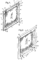
- Figures 1-13 schematically show one embodiment of a rectangular perimeter frame, generally 1, of this invention for an architectural opening, such as a window.
- the perimeter frame 1 comprises first, second, third and fourth elongate frame members 3, 5, 7 and 9, the ends of which are connected to each other by first, second, third and fourth, nodal or corner assemblies 11, 13, 15 and 17, respectively, of this invention.
- a sheet-like panel member 19, such as an insect screen, is attached in a conventional manner to the frame members 3, 5, 7 and 9 to cover an area surrounded by the perimeter frame 1.
- Extending from the rear of each corner assembly 11, 13, 15 and 17 is a hook-shaped retainer 21, 23, 25 and 27, respectively, each having a hook-shaped first end part 22, 24, 26 and 28, respectively, which will be described below in relation to Figures 8-13.
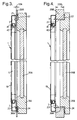
- Figure 3 shows a first type of window frame 29A hingedly carrying a pane frame 31A.
- the window frame 29A has only a shallow thickness 33A which is common to metal window frames.
- the hinged pane frame 31A can be made of metal, wood or plastic and contains a glass pane 35A.
- the rear sides of the frame members 3, 5, 7 and 9 (9 not shown in Figure 3) of the perimeter frame 1 of this invention audits corner assemblies 11, 13, 15 and 17 rest against the front of the window frame 29A, with the hook-shaped end parts 22, 24, 26 and 28 (26 and 28 not shown in Figure 3) of the retainers 21, 23, 25 and 27 (25 and 27 not shown in Figure 3) of the corner assemblies engaging adjacent rear sides of the widow frame 29A to hold the perimeter frame and its sheet-like panel 19 in place over the window opening 30 and also over the glass pane 35A when the hinged frame 31A is closed.
- each retainer 21, 23 , 25 and 27 need only extend rearwardly from the perimeter frame 1 and its corner assembly 11, 13, 15 and 17 by the rearward thickness 33A of the adjacent inner facing side 36A of the Figure 3-type window frame 29A. If the retainers 21, 23, 25 and 27 have sufficiently thin hook-shaped end parts 22, 24, 26 and 28, as is shown in Figure 3, they do not interfere with the closure of the pane frame 31A. With this arrangement, the sheet-like panel 19 in the perimeter frame 1 can remain in position when the pane frame 31A is closed.
- Figure 4 shows a second type of window frame 29B hingedly carrying a pane frame 31B that contains a glass pane 35B.
- the window frame 29B has a larger thickness 33B than does the window frame 29A of Figure 3.
- the window frame 29B can be made of wood or plastic, and the hinged pane frame 31B can be made of metal, wood or plastic.
- the hook-shaped end parts 22, 24, 26 and 28 of the retainer hooks 21, 23, 25 and 27 extend rearwardly from the perimeter frame 1 and its corner assemblies 11, 13, 15 and 17 by the substantial rearward thickness 33B of the respective adjacent inner facing sides 36B of the Figure 4-type window frame 29A.
- the retainers 21, 23, 25 and 27 and the corner assemblies 11, 13, 15 and 17 are preferably constructed in accordance with this invention to hold the perimeter frame 1 in place on the relatively thick window frame 31B of Figure 4, as well as the relatively thin window frame 31A of Figure 3. If the retainers 21, 23, 25 and 27 have sufficiently thin hook-shaped end parts 22, 24, 26 and 28, as is shown in Figure 4, they do not interfere with the closure of the pane frame 31B. With this arrangement, the sheet-like panel 19 in the perimeter frame 1 can remain in position when the pane frame 31B is closed.
- the perimeter frame may conveniently be hung on the outside of an inwardly opening window or on the inside of a outwardly opening window.
- the retainers 21, 23, 25 and 27 are preferably made from a relatively strong and durable metal or plastic, especially steel, particularly a conventional spring steel.
- the upper retainers 21 and 27 can, if desired, be made from a somewhat more flexible material than the lower retainers 23 and 25. However, for ease of stocking retainers 21-27, it may be preferable to use identical upper retainers 21 and 27 and lower retainers 23 and 25 in the perimeter frame 1.
- a spline 41 is preferably provided in a groove 42 formed in the inner facing side of each of the frame members 3, 5, 7 and 9 to hold the sheet-like panel 19 in the perimeter frame 1 of this invention.
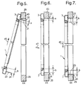
- Figures 5, 6 and 7 show the steps for installing the perimeter frame 1 in a window frame 29.
- the upper retainers 21 and 27 (27 not shown in Figures 5-7), with their upwardly extending, hook-shaped end parts 22 and 28, are pulled outwardly of their respective upper corner assemblies 11 and 17by a distance corresponding to the thickness of the frame 29.
- the upper retainers 21 and 27 are then urged against the upper jamb 43 of the window opening 29 and deflected downwardly to a distance "a" above the bottom of the upper horizontal frame member 3 of the perimeter frame 1 as shown in Figure 5.
- This downward deflection of retainers 21 and 27 can be obtained as shown by moving the entire perimeter flame 1 upwardly in the direction of arrow 45 against the bottom of the upper jamb 43 of the window frame 29.
- the lower retainers 23 and 25 (25 not shown in Figures 5-7) , with their downwardly extending, hook-shaped end parts 24 and 26, are then pulled outwardly of their respective lower corner assemblies 13 and 15 (if they have not already been so-pulled outwardly).
- the upper retainers 21 and 27 return to their relaxed positions at a similar distance "b" above the bottom of the upper frame member 3 as the distance "b” that the lower retainers 23 and 25 are below the top of the lower frame member 7.
- the hooked end parts 22, 24, 26 and 28 of the retainers 21, 23, 25 and 27 thereby engage the rear surfaces of the upper and lower jambs 43 and 44 of the window frame 29 to hold the perimeter frame 1 securely in the window opening 30.
- Figures 8-13 show details of two of the corner assemblies 11 and 13 of Figures 1-7.
- the other two corner assemblies 15 and 17 are mirror images of the corner assemblies 11 and 13, respectively.
- the upper corner assembly 11 has a central portion 50 with parallel front and rear sides 52 and 54.
- a relatively large opening 56 is provided in the rear side 54 of the central portion 50, through which the relatively vertically more flexible retainer 21 extends and from which its hooked end part 22 extends rearwardly of the central portion.
- the distance that the retainer 21 and its hook-shaped end part 22 extend rearwardly from the central portion 50 can be varied, and one possible further position is indicated as 21' by dotted lines.
- the retainer 21 can be moved, relative to the opening 56, in either direction of the double arrow 58 so that the retainer 21 extends away from the rear side 54 of the central portion 50 to greater or lesser extents.
- Figure 8 also shows the retainer 21 and its hook-shaped end part 22 being deflected downwardly to a position 21'', indicated by dotted lines.
- Such forced deflection and the resulting resilient relaxation of the retainer 21 is generally in the vertical direction of double arrow 59.
- This vertical movement of the retainer 21 is accommodated by the opening 56 which is relatively large in the vertical direction and optionally by the relatively more flexible nature of the retainer 21 which is preferably made of spring steel wire.
- the lower corner assembly 13 also has a central portion 60 and parallel front and rear sides 62 and 64.
- a relatively small opening 66 is provided in the rear side 64 of the central portion 60, through which the relatively less flexible retainer 23 extends and from which its hook-shaped end part 24 extends rearwardly of the corner assembly 13.
- the distance that the retainer 23 and its hook-shaped end part 24 of the lower corner assembly 13 extend rearwardly of the central portion 60 can be varied, and one possible further position is indicated as 23' by dotted lines.
- the retainer 23 can be moved, relative to the opening 66, in either direction of the double arrow 68 so that the retainer 23 extends from the rear side 64 of the central portion 60 to greater or lesser extents.
- the lower corner assemblies 13 and 15 support the weight of the perimeter frame 1 and its sheet-like panel 19. For this reason, their retainers 23 and 25 preferably are not allowed to be deflected significantly upwardly by the weight of the perimeter frame 1 as shown in Figure 9. Such limited vertical movement of the retainers 23 and 25 is obtained by providing openings 66 in the rear sides 64 of their central portions 60 that are relatively small vertically and by making the retainers 23 and 25, if necessary, relatively inflexible, preferably of spring steel wire.
- Figures 8 and 9 also show that the rear sides 54 and 64 of the central portions 50 and 60 of the upper and lower corner assemblies 11 and 13, as well as of the other upper and lower corner assemblies 15 and 17 (not shown), are provided with an additional, unused opening 56A and 66A, respectively.
- each of the upper and lower retainers 21 and 23, as well as each of the other upper and lower retainers 27 and 25 (not shown), can alternatively be extended from these additional openings 56A and 66A.
- the corner assemblies 11 and 13 of Figures 8 and 9, as well the corner assemblies 15 and 17 (not shown) can be placed in either right or left hand positions in the perimeter frame 1 of this invention.
- the right hand corner assemblies 11 and 13 as shown in Figures 1-8 can also be used on the left hand side of the perimeter frame 1 as its corner assemblies 15 and 17, respectively, as shown in Figures 1-8. This allows a substantial reduction in the number of different components which have to be manufactured and stocked for the perimeter frame 1.
- first and second legs 72 and 74 extending at right angles to each other from the central portion 50 of the corner assembly 11 and parallel to the first and second sides 52 and 54, are inserted in the adjacent open ends of the frame member 3 and 5 in a conventional manner and are thereby hidden from view.
- first and second legs 72 and 74 (not shown), extending at right angles to each other from the central portion 60 of the corner assembly 13 and parallel to the first and second sides 62 and 64, are inserted in the open ends of the adjacent frame member 5 and 7 in a conventional manner in Figure 9 and are thereby hidden from view.
- first and second legs 72 and 74 (not shown), extending at right angles to each other from each central portion 50 or 60 of the each of the other corner assemblies 15 and 17, are inserted in the ends of the adjacent frame member 3, 5, 7 and 9 in a conventional manner and are thereby also hidden from view.
- the corner assemblies 11, 13, 15 and 17 of this invention including their central portions 50 and 60 and their legs 72 and 74 and their attachment to the frame members 3, 5, 7, and 9, are conventional, except for their retainers 21, 23, 25 and 27 and their interior structures, as described below, by which the retainers can be extended or retracted and their hook-shaped end parts 22, 24, 26 and 28 can be held on to an architectural opening.
- Figures 10-13 show details of the interiors of the central portion 50 and first leg 72 of the corner assembly 11 which are typical of a central portion and a leg of at least the upper corner assemblies 11 and 17 of this invention.
- the first leg 72 serves, in a conventional manner, to hold the corner assembly 11 and its central portion 50 in sliding engagement with the hollow interior of an adjacent frame members (such as 3).
- the interior of the central portion 50 and first leg 72 serve also to hold and restrain movement of the portions of the retainer 21 which do not extend rearwardly and outwardly from the central portion 50through its opening 56 or 56A.
- Figures 10 and 12 show the retainer 21 in its relatively unextended and undeflected position relative to the interiors of the central portion 50 and first leg 72.
- Figure 11 shows the retainer 21 in its extended position 21'
- Figure 13 shows the retainer 21 in its deflected position 21'' relative to the interiors of the first leg 72 and the central portion 50.
- the interior of the first leg 72 contains an elongated cavity 76 which contains an elongated serpentine, preferably horizontally serpentine, second end part 90, of the retainer 21.
- the cavity 76 and the second end part 90 of the retainer 21 are both elongated in a direction along the length of the leg 72, i.e., parallel to the first and second sides 52 and 54 of the central portion 50.
- the cavity 76 be open at the rear side of the corner assembly 11, preferably along substantially the entire length of the cavity 76, to allow the elongated second end part 90 of the retainer 21 to be easily inserted therein with its hook-shaped end part 22 extending outwardly of the opening 56 in the central portion 50.
- the crests 92 and 94 on opposite sides of the serpentine second end part 90 of the retainer 21 resiliently engage the front and rear walls 78 and 79 of the cavity 76 to frictionally restrain movement of the serpentine second end part 90 of the retainer 21 within the cavity 76.
- the serpentine configuration of the second end part 90 also serves to keep the retainer 21 from twisting in the cavity 76 so that its hook-shaped end part 22 stays in proper orientation for engaging a window frame 29.
- the cavity 76 in the first leg 72 is connected, through a rearwardly extending channel 57 in the central portion 50 of the corner assembly 11, to the opening 56 at the rear side 54 of the central portion 50.
- the channel 57 in the central portion 50 is also open at one side of the corner assembly 11 to allow a central part 96 of the retainer 21 to be easily inserted therein.
- the central part 96 of the retainer 21 extends through the channel 57 and the opening 56 and becomes thereby rearwardly curved.
- Figures 12 and 13 show one of the upper corner assemblies 11 and in particular show that, in its first leg 72, the end of the cavity 76 remote from the central portion 50 is relatively narrow in the vertical plane, but the cavity 76 gradually widens vertically towards its other end, as it joins the channel 57. Likewise, the channel 57 gradually widens vertically as it goes from its end in communication with the cavity 76 to the opening 56 in the rear side 54 of the central portion 50. This profile of the cavity 76 allows relatively resilient deflection of the retainer 21 outside of the corner assembly 11 (as shown in Figure 8).
- each cavity 76 and channel 57 are preferably of constant width vertically and do not widen gradually as they go towards the opening 66, which is vertically smaller than the corresponding opening 56 in the upper corner assemblies.
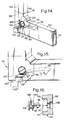
- Figures 14-16 show another embodiment of a corner assembly 115 of the invention which is similar to the corner assembly 15 of Figures 1-13 and for which the same reference numerals or corresponding reference numerals (greater by 100) are used below for describing the same parts or corresponding parts, respectively.
- the corner assembly 115 has a central portion 160 connected to a pair of perpendicular legs 72 and 74 (hidden from view) inserted in adjacent frame members 107 and 109 of a perimeter frame of this invention.
- the rear side 164 of the central portion 160 has rectangular openings 166 and 166A, from one of which 166 a retainer 125 extends rearwardly.
- the retainer 125 is generally rearwardly curved and arc-shaped and includes: a hook-shaped end part 126; an elongate other end part 190 within a cavity 76 (not shown) within the first leg 107; and a central part 196.
- the retainer 125 also has a rectangular cross-section that is wider than it is thick to give the retainer enhanced torsional stability.
- the rectangular cross-section of the elongate end part 190 and central part 196 of the retainer 125 conforms closely to the rectangular cross-sections of the opening 166 and 166A and the cavity 76, so that there is a close fit of the retainer in the cavity and openings to keep the retainer from twisting and so that its hook-shaped end part 126 stays in proper orientation for engaging a window frame.
- the central part 196 of the retainer 125 has saw tooth serrations 197 on its upper surface for engagement with a worm screw member 145 mounted on the rear side 164 of the central portion 160.
- the openings 166 and 166A prior to use, can be closed by a break-through wall portion which then can be selectively removed depending on the opening 166 and 166A, through which the retainer 125 is to extend. Only the opening 166 and 166A, from which the retainer 125 is to extend, then needs to be removed, and the exterior surface of the corner assembly 115 can thereby retain a generally smooth and closed appearance.
- Figure 15 also shows schematically the arc-shaped other end part 190 and central part 196 of the retainer 125, which enable the retainer to move through an arc shaped path, so that its movement between position 125' and position 125'' corresponds to an angular track ⁇ .
- Figure 16 shows a preferred worm screw 145A that is snap-fit in a cavity 146 in the rear side 164 of the central portion 160 in a direction generally indicated by arrow 147.
- the worm screw 145A is provided with a bifurcated end 148, resiliently carrying detent surfaces 149 which can engage corresponding detent surfaces 149A within the cavity 146 of the central portion 160.
- the worm screw 145A is provided with a helical thread 198.
- the worm screw 145 or 145A can be freely rotated in both directions to adjust the retainer 125 inwardly and outwardly of the central portion 160 through engagement of the saw tooth serrations 197.
- a hook-shaped end part 126 of the retainer 125 extends outwardly of the aperture 166.
- the retainer 125 can be moved inwardly and outwardly of the aperture 166, whereby its elongated, rearwardly curved, second end part 190 and its rearwardly-curved central part 196 can be moved inwardly and outwardly of the elongate cavity 76 within the first leg 72 and the connecting channel 57 within the central portion 160.
- the worm screw 145 is provided with a conventional head portion 199, by which it can be rotated.
- the head portion 199 is provided with a recessed slot 200 for engagement by a screw driver or the like.
- FIGS 17-19 show a further embodiment of a perimeter frame 201 which is similar to the perimeter frame 1 of Figures 1-13 and for which the same reference numerals or corresponding reference numerals (greater by 200) are used below for describing the same parts or corresponding parts, respectively.
- the perimeter frame 201 includes four corner assemblies 211, 213, 215 and 217 of the invention which are similar to the corner assembly 115 of Figures 14-16 and for one of which 213 the same reference numerals or corresponding reference numerals (greater by 100) are used below for describing the same parts or corresponding parts, respectively.
- the corner assembly 213 has a central portion 260 connected to a pair of perpendicular legs 72 and 74 (hidden from view) inserted in adjacent frame members 205 and 207 of the perimeter frame 201.
- the perimeter frame 201 is preferably provided with hand grips 202 which facilitate the manipulation of the perimeter frame when fitting it into a window opening frame 30 (not shown).
- the hand grips 202 can thereby also help to prevent damage to its screen-like panel 219.
- These hand grips or other similar handles are also preferably included in any of the embodiments to facilitate installation.
- the corner assembly 213 is provided with two apertures 266 and 266A in the rear side 264 of its central portion 260.
- a hook-shaped end part 224 of a retainer 223 extends outwardly of the aperture 266.
- the retainer 223 can be moved inwardly and outwardly of the aperture 266, whereby its elongate second end part 290 and its rearwardly-curved central part 296 can be moved inwardly and outwardly of the elongate cavity 76 (not shown) within the first leg 72 and the connecting channel 57 within the central portion 260.
- a like arrangement can be seen on the other corner assemblies 211, 215 and 217.
- Figure 18 shows the worm screw 245 and the retainer 223 free from the surrounding structure of the corner assembly 213.
- a helical screw thread 298 engages a segment of gear teeth 297 on the outwardly curved edge of the arc-shaped central portion 296 of the retainer 223.
- the worm screw 245 has a first screw driver slot 300 in its head portion 299 and a second screw driver slot 300A at its opposite axial end.
- Each of the screw driver slots 300 and 300A is engageable from a respective opposite side of the screen-like panel 219 so that adjustments can be made from inside and outside the building and the window opening, to which the screen panel 219 has been fitted.
- the operating feature for instance the screw driver slot
- the operating feature preferably faces inwardly where they can be operated to retract the retainers so as to hold the perimeter frames securely on the outside of the windows.
- the operating features eg the worm screws, could also be mounted so that their head portions could be reached from the outside of the perimeter frames are to be held on the inside of the windows.
- Figure 19 shows the worm screw 245 and the retainer 223 from the bottom rear of the corner assembly 213.
- a reference “x” denotes the distance between the hook-shaped end 224 of the retainer 223 from the rear side 264 of the corner assembly 213.
- the invention as embodied in Figures 14 to 19 can be combined with that as embodied in Figures 1-13.
- the spring steel hooks of Figures 1 to 13 can each be mounted on one end of an elongated spring steel central part (like the central part 96 of Figures 10 to 13) which, in turn, is connected to a curved toothed plastic member like the central part 196,296 of Figures 14 to 19.
- a worm screw can engage the toothed plastic member so as to extend and retract the spring steel hook.
- a spring steel member could itself be formed with means to engage some operating feature.
- the spring steel member could itself include teeth for engagement with a worm screw or, indeed, the serpentine section of Figures 10 to 13 could itself be engaged by a worm screw to affect extension and retraction of the hook.
- the perimeter frames 1 and 201 of this invention not only improve the positioning of a screen-like panel 19 and 219 in a window opening 30 but also hold such a screen-like panel in position without any play on a variety of window opening edges. This allows for easy mounting and adjustment of a screen-like panel with simple and cost-effective methods and tools.
- a particular advantage of the corner assemblies 11, 13, 15, 17, 115, 211, 213, 215 and 217 of these perimeter frames is that they can be used in prefabricated window systems, in which drilling of holes is not permitted.
- Another advantage is that the screen-like panel can be left in position while the window is closed.
- the windows described with respect to Figures 2-7 usually are provided with a hinged pane opening towards the inside of a building, but in certain countries, there is a preference for windows opening to the outside of a building which may result in an inverse arrangement of parts of the corner assemblies of this invention but which should otherwise be considered to be within the scope of the invention.
Abstract
Description
- This invention relates to a nodal assembly, particularly a corner assembly, for a peripheral frame which can be removably mounted on a architectural opening. This invention quite particularly relates to a corner assembly for the frame of an insect screen for a window opening.
- Corner assemblies of frames that can be used to removably mount framed insect screens and other sheet-line panels on windows and doors are known, for example, from US patent 5,431,211 and UK patent application GB 2,236,134A. US patent 5,431,211, in particular, describes an insect screen that has a frame with a corner assembly having a retaining protrusion which is: i) slidably held within the corner assembly and ii) can be slid outwardly of a longitudinal side of the corner assembly and into a suitable recess provided in the window frame to hold the screen on the window. However, the windows and doors, to which such a corner assembly has been attached, have had to be specially provided with suitable recesses which could accept and hold the retaining protrusion of the corner assembly.
- In accordance with this invention, a nodal assembly, particularly a corner assembly, is provided for collecting at least two adjacent frame members of a perimeter frame, the nodal element comprising:
- a central portion having parallel first and second sides and an opening in the second side;
- a first leg extending from the central portion in a first direction parallel to the first side and having a cavity within it in communication with the opening;
- a second leg extending from the central portion in a second direction different from the first direction but also parallel to the first side; and
- a retainer slidably received in the cavity and movable between a retracted position substantially within the central portion and the first leg and an extended position in which the retainer extends substantially outwardly of the opening in the second side of the central portion and away from the second side.
- In accordance with one aspect of the nodal assembly of the invention: the first and second sides of the central portion are laterally opposite sides, preferably front and rear sides; the cavity in the first leg is substantially parallel to the first leg; one end of the cavity is in communication with one end of a channel in the central portion; and the other end of the channel is in communication with the opening in the central portion.
- In accordance with another aspect of the nodal assembly of the invention: the retainer comprises:
- an elongated part at one end, preferably a front end part, which is slidably received in the cavity in the first leg and in the channel, if present, and which can be moved outwardly, preferably rearwardly, of the second side of the central portion through the opening in the second side; and
- a hook-shaped part at its other end, preferably a rear end part, which is located outwardly, preferably rearwardly, of the second side of the central portion; the retainer, in its retracted position, having a central part substantially within the cavity in the first leg and in its extended position, having its central part extending outwardly of the cavity through the opening in the central portion and away from, preferably rearwardly of, the second side of the central portion.
- Also in accordance with this invention, a perimeter frame is provided comprising:
- a plurality of elongate frame members;
- a plurality of the nodal assemblies described above, each nodal assembly having first and second legs engaging the ends of two adjacent frame members to form the perimeter frame and a retainer; and optionally
- a sheet-like panel attached to the perimeter frame to cover an area defined by the perimeter frame; each of the retainers being adapted to engage a window opening having a contour corresponding to the perimeter frame so that the sheet-like panel, if present, covers the window opening.
- Further aspects of the invention will be apparent from the detailed description below of particular embodiments and the drawings thereof, in which:
- Figure 1 is a perspective view of the rear of one embodiment of a perimeter frame for a sheet-like panel, having four corner assemblies of this invention.
- Figure 2 is a perspective view of the rear of a window frame or jamb having an opening in which the perimeter frame of Figure 1 is installed.
- Figure 3 is a schematic cross-sectional view of the perimeter frame of Figures 1 and 2 installed on a first embodiment of a window frame similar to that in Figure 2, taken along line C-C of Figure 2.
- Figure 4 is a schematic cross-sectional view of the perimeter frame of Figures 1 and 2 installed on a second embodiment of a window frame similar to that in Figure 2, taken along line C-C of figure 2.
- Figures 5, 6 and 7 are schematic cross-sectional views of several steps in the process of installing the perimeter frame on the window frame of Figure 2, taken along line C-C of Figure 2; Figure 7 shows the final mounted position of the perimeter frame on the window frame.
- Figure 8 is an enlarged detail view of a corner assembly "X" of Figure 1, showing several positions of a vertically more flexible, slidable retainer in the corner assembly.
- Figure 9 is an enlarged detail view of another corner assembly "Y" of Figure 1, showing two positions of a vertically less flexible, slidable retainer in the corner assembly.
- Figure 10 is a schematic cross-sectional view in a horizontal plane, taken along line X-X in Figure 8, with the vertically more flexible retainer in a retracted position.
- Figure 11 is a schematic view similar to Figure 10 with the vertically more flexible retainer in a extended position.
- Figure 12 is a schematic cross-sectional view in a vertical plane, taken along line XII-XII in Figures 8 and 10 with the vertically more flexible retainer in a non-deflected position.
- Figure 13 is a schematic view similar to Figure 12 with the vertically more flexible retainer in a downwardly deflected position.
- Figure 14 is an enlarged schematic detail view, similar to Figure 8 and 9, of another embodiment of a corner assembly of this invention, shown as a left-hand bottom corner detail of a perimeter frame.
- Figure 15 is a schematic top plan view of the corner assembly of Figure 14.
- Figure 16 is a schematic partial vertical cross-sectional view through the corner assembly of Figure 14, showing an exploded arrangement of an adjusting device.
- Figure 17 is a perspective view, similar to Figure 1, of the rear of a perimeter frame for a sheet-like panel having four further embodiments of a corner assembly of this invention.
- Figure 18 a schematic perspective view of components of a corner assembly of Figure 17 in their operative positions but free from the surrounding structure of the corner assembly.
- Figure 19 is a schematic bottom view of the components of Figure 18.
- Figures 1-13 schematically show one embodiment of a rectangular perimeter frame, generally 1, of this invention for an architectural opening, such as a window.
- As best seen in Figure 1, the
perimeter frame 1 comprises first, second, third and fourthelongate frame members corner assemblies like panel member 19, such as an insect screen, is attached in a conventional manner to theframe members perimeter frame 1. Extending from the rear of eachcorner assembly shaped retainer first end part - As seen in Figure 2, when the
perimeter frame 1 is installed in a window frame, generally 29, the a hook-shapedfirst end parts retainers widow frame 29 to hold the perimeter frame and its sheet-like panel 19 in place over the window opening 30. - Figure 3 shows a first type of
window frame 29A hingedly carrying apane frame 31A. Thewindow frame 29A has only ashallow thickness 33A which is common to metal window frames. The hingedpane frame 31A can be made of metal, wood or plastic and contains aglass pane 35A. The rear sides of theframe members perimeter frame 1 of this inventionaudits corner assemblies window frame 29A, with the hook-shaped end parts retainers widow frame 29A to hold the perimeter frame and its sheet-like panel 19 in place over the window opening 30 and also over theglass pane 35A when thehinged frame 31A is closed. - As seen in Figures 2 and 3, the hook-
shaped end part retainer perimeter frame 1 and itscorner assembly rearward thickness 33A of the adjacent inner facingside 36A of the Figure 3-type window frame 29A. If theretainers shaped end parts pane frame 31A. With this arrangement, the sheet-like panel 19 in theperimeter frame 1 can remain in position when thepane frame 31A is closed. - Figure 4 shows a second type of
window frame 29B hingedly carrying apane frame 31B that contains aglass pane 35B. Thewindow frame 29B has a larger thickness 33B than does thewindow frame 29A of Figure 3. Thewindow frame 29B can be made of wood or plastic, and the hingedpane frame 31B can be made of metal, wood or plastic. The rear sides of theflame members perimeter frame 1 of this invention and its corner assemblies 11, 13, 15 and 17 rest against the front of thewindow frame 29B, with the hook-shaped end parts retainer hooks widow frame 29B to hold the perimeter frame and its sheet-like panel 19 in place over the window opening 30 and over theglass pane 35B if it is closed. - As seen in Figure 4, the hook-
shaped end parts retainer hooks perimeter frame 1 and itscorner assemblies sides 36B of the Figure 4-type window frame 29A. Thus, theretainers perimeter frame 1 in place on the relativelythick window frame 31B of Figure 4, as well as the relativelythin window frame 31A of Figure 3. If theretainers shaped end parts pane frame 31B. With this arrangement, the sheet-like panel 19 in theperimeter frame 1 can remain in position when thepane frame 31B is closed. - As will be appreciated from the above, the perimeter frame may conveniently be hung on the outside of an inwardly opening window or on the inside of a outwardly opening window.
- The
retainers upper retainers lower retainers upper retainers lower retainers perimeter frame 1. - As also shown in Figures 3 and 4, a
spline 41 is preferably provided in agroove 42 formed in the inner facing side of each of theframe members like panel 19 in theperimeter frame 1 of this invention. - Figures 5, 6 and 7 show the steps for installing the
perimeter frame 1 in awindow frame 29. Initially, theupper retainers 21 and 27 (27 not shown in Figures 5-7), with their upwardly extending, hook-shaped end parts upper corner assemblies 11 and 17by a distance corresponding to the thickness of theframe 29. Theupper retainers upper jamb 43 of the window opening 29 and deflected downwardly to a distance "a" above the bottom of the upperhorizontal frame member 3 of theperimeter frame 1 as shown in Figure 5. This downward deflection ofretainers entire perimeter flame 1 upwardly in the direction ofarrow 45 against the bottom of theupper jamb 43 of thewindow frame 29. - As shown in Figure 6, the
lower retainers 23 and 25 (25 not shown in Figures 5-7) , with their downwardly extending, hook-shapedend parts lower corner assemblies 13 and 15 (if they have not already been so-pulled outwardly). Thelower retainers horizontal frame member 7 of theperimeter frame 1, are then moved over thelower jamb 44 of thewindow frame 29 by swinging theperimeter frame 1 rearwardly in the direction ofarrow 47. - When the
perimeter frame 1 is thereafter allowed to move downwardly as indicated byarrow 49 in Figure 7, theupper retainers upper frame member 3 as the distance "b" that thelower retainers lower frame member 7. As also seen in Figure 7, thehooked end parts retainers lower jambs window frame 29 to hold theperimeter frame 1 securely in thewindow opening 30. - Figures 8-13 show details of two of the
corner assemblies corner assemblies corner assemblies - As seen in Figure 8, the
upper corner assembly 11 has acentral portion 50 with parallel front andrear sides large opening 56 is provided in therear side 54 of thecentral portion 50, through which the relatively vertically moreflexible retainer 21 extends and from which itshooked end part 22 extends rearwardly of the central portion. The distance that theretainer 21 and its hook-shapedend part 22 extend rearwardly from thecentral portion 50 can be varied, and one possible further position is indicated as 21' by dotted lines. In this regard, theretainer 21 can be moved, relative to theopening 56, in either direction of thedouble arrow 58 so that theretainer 21 extends away from therear side 54 of thecentral portion 50 to greater or lesser extents. - Figure 8 also shows the
retainer 21 and its hook-shapedend part 22 being deflected downwardly to a position 21'', indicated by dotted lines. Such forced deflection and the resulting resilient relaxation of theretainer 21 is generally in the vertical direction ofdouble arrow 59. This vertical movement of theretainer 21 is accommodated by theopening 56 which is relatively large in the vertical direction and optionally by the relatively more flexible nature of theretainer 21 which is preferably made of spring steel wire. - As seen in Figure 9, the
lower corner assembly 13 also has acentral portion 60 and parallel front andrear sides small opening 66 is provided in therear side 64 of thecentral portion 60, through which the relatively lessflexible retainer 23 extends and from which its hook-shapedend part 24 extends rearwardly of thecorner assembly 13. As with theupper corner assembly 11 of Figure 8, the distance that theretainer 23 and its hook-shapedend part 24 of thelower corner assembly 13 extend rearwardly of thecentral portion 60 can be varied, and one possible further position is indicated as 23' by dotted lines. In this regard, theretainer 23 can be moved, relative to theopening 66, in either direction of thedouble arrow 68 so that theretainer 23 extends from therear side 64 of thecentral portion 60 to greater or lesser extents. - The
lower corner assemblies perimeter frame 1 and its sheet-like panel 19. For this reason, theirretainers perimeter frame 1 as shown in Figure 9. Such limited vertical movement of theretainers openings 66 in therear sides 64 of theircentral portions 60 that are relatively small vertically and by making theretainers - Figures 8 and 9 also show that the
rear sides central portions lower corner assemblies lower corner assemblies 15 and 17 (not shown), are provided with an additional,unused opening lower retainers lower retainers 27 and 25 (not shown), can alternatively be extended from theseadditional openings corner assemblies corner assemblies 15 and 17 (not shown), can be placed in either right or left hand positions in theperimeter frame 1 of this invention. For example, by repositioning theretainers openings corner assemblies hand corner assemblies perimeter frame 1 as itscorner assemblies perimeter frame 1. - In Figures 1-8, first and
second legs central portion 50 of thecorner assembly 11 and parallel to the first andsecond sides frame member second legs 72 and 74 (not shown), extending at right angles to each other from thecentral portion 60 of thecorner assembly 13 and parallel to the first andsecond sides adjacent frame member second legs 72 and 74 (not shown), extending at right angles to each other from eachcentral portion other corner assemblies adjacent frame member corner assemblies central portions legs frame members retainers end parts - Figures 10-13 show details of the interiors of the
central portion 50 andfirst leg 72 of thecorner assembly 11 which are typical of a central portion and a leg of at least theupper corner assemblies first leg 72 serves, in a conventional manner, to hold thecorner assembly 11 and itscentral portion 50 in sliding engagement with the hollow interior of an adjacent frame members (such as 3). The interior of thecentral portion 50 andfirst leg 72 serve also to hold and restrain movement of the portions of theretainer 21 which do not extend rearwardly and outwardly from the central portion 50through itsopening retainer 21 in its relatively unextended and undeflected position relative to the interiors of thecentral portion 50 andfirst leg 72. Figure 11 shows theretainer 21 in its extended position 21' and Figure 13 shows theretainer 21 in its deflected position 21'' relative to the interiors of thefirst leg 72 and thecentral portion 50. - As seen from Figures 10-13, the interior of the
first leg 72 contains anelongated cavity 76 which contains an elongated serpentine, preferably horizontally serpentine,second end part 90, of theretainer 21. Preferably, thecavity 76 and thesecond end part 90 of theretainer 21 are both elongated in a direction along the length of theleg 72, i.e., parallel to the first andsecond sides central portion 50. It is also preferred that thecavity 76 be open at the rear side of thecorner assembly 11, preferably along substantially the entire length of thecavity 76, to allow the elongatedsecond end part 90 of theretainer 21 to be easily inserted therein with its hook-shapedend part 22 extending outwardly of theopening 56 in thecentral portion 50. Thecrests second end part 90 of theretainer 21 resiliently engage the front andrear walls cavity 76 to frictionally restrain movement of the serpentinesecond end part 90 of theretainer 21 within thecavity 76. The serpentine configuration of thesecond end part 90 also serves to keep theretainer 21 from twisting in thecavity 76 so that its hook-shapedend part 22 stays in proper orientation for engaging awindow frame 29. - As also seen from Figures 10-13, the
cavity 76 in thefirst leg 72 is connected, through arearwardly extending channel 57 in thecentral portion 50 of thecorner assembly 11, to theopening 56 at therear side 54 of thecentral portion 50. Preferably, thechannel 57 in thecentral portion 50 is also open at one side of thecorner assembly 11 to allow acentral part 96 of theretainer 21 to be easily inserted therein. Thecentral part 96 of theretainer 21 extends through thechannel 57 and theopening 56 and becomes thereby rearwardly curved. The curvedcentral part 96 of theretainer 21, together with guiding surfaces on the edges of opening 56, ensure that the hook-shapedend part 22 of theretainer 21 is readily movable towards and away from therear side 54 of thecentral portion 50 of thecorner assembly 11 along a curved path. The structure described above regarding: i) the elongated serpentinesecond end part 90 of theretainer 21, within theelongated cavity 76 of thefirst leg 72, ii) the curvedcentral part 96 of the retainer, within thechannel 57 and theopening 56 in therear side 54 of thecentral portion 50, and iii) the hook-shapedend part 22 outside and rearward of therear side 54 of thecentral portion 50 of thecorner assembly 11 are typical of all thecorner assemblies perimeter frame 1 of this invention. - Figures 12 and 13 show one of the
upper corner assemblies 11 and in particular show that, in itsfirst leg 72, the end of thecavity 76 remote from thecentral portion 50 is relatively narrow in the vertical plane, but thecavity 76 gradually widens vertically towards its other end, as it joins thechannel 57. Likewise, thechannel 57 gradually widens vertically as it goes from its end in communication with thecavity 76 to theopening 56 in therear side 54 of thecentral portion 50. This profile of thecavity 76 allows relatively resilient deflection of theretainer 21 outside of the corner assembly 11 (as shown in Figure 8). In Figure 13, theretainer 21 is shown in its deflected position 21'', but normally, the retainer will not stay in the deflected position 21'' shown in Figure 13 but will, in fact, be resiliently biased towards its undeflected position as shown in Figure 12. In theperimeter frame 1, the otherupper corner assembly 17 will also have this structure for itscavity 76 andchannel 57. However in thelower corner assemblies cavity 76 andchannel 57 are preferably of constant width vertically and do not widen gradually as they go towards the opening 66, which is vertically smaller than thecorresponding opening 56 in the upper corner assemblies. - Figures 14-16 show another embodiment of a
corner assembly 115 of the invention which is similar to thecorner assembly 15 of Figures 1-13 and for which the same reference numerals or corresponding reference numerals (greater by 100) are used below for describing the same parts or corresponding parts, respectively. - The
corner assembly 115 has acentral portion 160 connected to a pair ofperpendicular legs 72 and 74 (hidden from view) inserted inadjacent frame members rear side 164 of thecentral portion 160 hasrectangular openings retainer 125 extends rearwardly. Theretainer 125 is generally rearwardly curved and arc-shaped and includes: a hook-shapedend part 126; an elongateother end part 190 within a cavity 76 (not shown) within thefirst leg 107; and acentral part 196. Theretainer 125 also has a rectangular cross-section that is wider than it is thick to give the retainer enhanced torsional stability. Preferably, the rectangular cross-section of theelongate end part 190 andcentral part 196 of theretainer 125 conforms closely to the rectangular cross-sections of theopening cavity 76, so that there is a close fit of the retainer in the cavity and openings to keep the retainer from twisting and so that its hook-shapedend part 126 stays in proper orientation for engaging a window frame. - The
central part 196 of theretainer 125 hassaw tooth serrations 197 on its upper surface for engagement with aworm screw member 145 mounted on therear side 164 of thecentral portion 160. Theopenings opening retainer 125 is to extend. Only theopening retainer 125 is to extend, then needs to be removed, and the exterior surface of thecorner assembly 115 can thereby retain a generally smooth and closed appearance. - In Figure 15, two positions of the
retainer 125 are shown. In a first position 125', the hook-shapedend part 126 of the retainer is at a distance "c" from therear side 164 of thecentral portion 160. A suitable minimum distance "c" for the first position 125' could be about 5mm. In asecond position 125", the hook-shapedend part 126 of theretainer 125 is at a distance "d" from therear side 164 of thecentral portion 160. A suitable maximum distance "d" for thesecond position 125" would be about 20 mm or more. - Figure 15 also shows schematically the arc-shaped
other end part 190 andcentral part 196 of theretainer 125, which enable the retainer to move through an arc shaped path, so that its movement between position 125' and position 125'' corresponds to an angular track α. - Figure 16 shows a
preferred worm screw 145A that is snap-fit in acavity 146 in therear side 164 of thecentral portion 160 in a direction generally indicated byarrow 147. Theworm screw 145A is provided with abifurcated end 148, resiliently carryingdetent surfaces 149 which can engage corresponding detent surfaces 149A within thecavity 146 of thecentral portion 160. To engage thesaw tooth serrations 197 on the top surface of theretainer 125, theworm screw 145A is provided with ahelical thread 198. - Once the
worm screw central portion 160, it can be freely rotated in both directions to adjust theretainer 125 inwardly and outwardly of thecentral portion 160 through engagement of thesaw tooth serrations 197. In this regard, a hook-shapedend part 126 of theretainer 125 extends outwardly of theaperture 166. By means of theworm screw 145, theretainer 125 can be moved inwardly and outwardly of theaperture 166, whereby its elongated, rearwardly curved,second end part 190 and its rearwardly-curvedcentral part 196 can be moved inwardly and outwardly of theelongate cavity 76 within thefirst leg 72 and the connectingchannel 57 within thecentral portion 160. - As seen in Figure 14, the
worm screw 145 is provided with aconventional head portion 199, by which it can be rotated. In this regard, thehead portion 199 is provided with a recessedslot 200 for engagement by a screw driver or the like. - Figures 17-19 show a further embodiment of a
perimeter frame 201 which is similar to theperimeter frame 1 of Figures 1-13 and for which the same reference numerals or corresponding reference numerals (greater by 200) are used below for describing the same parts or corresponding parts, respectively. Theperimeter frame 201 includes fourcorner assemblies corner assembly 115 of Figures 14-16 and for one of which 213 the same reference numerals or corresponding reference numerals (greater by 100) are used below for describing the same parts or corresponding parts, respectively. In this regard, the corner assembly 213 has acentral portion 260 connected to a pair ofperpendicular legs 72 and 74 (hidden from view) inserted inadjacent frame members perimeter frame 201. - The
perimeter frame 201 is preferably provided withhand grips 202 which facilitate the manipulation of the perimeter frame when fitting it into a window opening frame 30 (not shown). The hand grips 202 can thereby also help to prevent damage to its screen-like panel 219. These hand grips or other similar handles are also preferably included in any of the embodiments to facilitate installation. - The corner assembly 213 is provided with two
apertures central portion 260. A hook-shapedend part 224 of aretainer 223 extends outwardly of theaperture 266. By means of aworm screw 245 on the rear side 264 of thecentral portion 260, theretainer 223 can be moved inwardly and outwardly of theaperture 266, whereby its elongatesecond end part 290 and its rearwardly-curvedcentral part 296 can be moved inwardly and outwardly of the elongate cavity 76 (not shown) within thefirst leg 72 and the connectingchannel 57 within thecentral portion 260. A like arrangement can be seen on theother corner assemblies - Figure 18 shows the
worm screw 245 and theretainer 223 free from the surrounding structure of the corner assembly 213. In this embodiment, ahelical screw thread 298 engages a segment ofgear teeth 297 on the outwardly curved edge of the arc-shapedcentral portion 296 of theretainer 223. It is also seen that in this embodiment, theworm screw 245 has a firstscrew driver slot 300 in itshead portion 299 and a secondscrew driver slot 300A at its opposite axial end. - Each of the
screw driver slots like panel 219 so that adjustments can be made from inside and outside the building and the window opening, to which thescreen panel 219 has been fitted. - For embodiments having worm screws or other similar mechanisms for extending and retracting the hooks, it is possible to locate the operating feature, for instance the screw driver slot, one either side of the perimeter frame relative to extension of the hook. However, where perimeter frames are hung on the outside of windows, the operating feature preferably faces inwardly where they can be operated to retract the retainers so as to hold the perimeter frames securely on the outside of the windows. Of course, the operating features, eg the worm screws, could also be mounted so that their head portions could be reached from the outside of the perimeter frames are to be held on the inside of the windows.
- Figure 19 shows the
worm screw 245 and theretainer 223 from the bottom rear of the corner assembly 213. A reference "x" denotes the distance between the hook-shapedend 224 of theretainer 223 from the rear side 264 of the corner assembly 213. - The invention as embodied in Figures 14 to 19 can be combined with that as embodied in Figures 1-13. In particular, it is possible to combine the use of the spring steel hooks of Figures 1 to 13 with an operating mechanism, such as the worm screws of Figures 14 to 19. As one example, the spring steel hooks can each be mounted on one end of an elongated spring steel central part (like the
central part 96 of Figures 10 to 13) which, in turn, is connected to a curved toothed plastic member like the central part 196,296 of Figures 14 to 19. In this way, a worm screw can engage the toothed plastic member so as to extend and retract the spring steel hook. As another example, a spring steel member could itself be formed with means to engage some operating feature. For instance, the spring steel member could itself include teeth for engagement with a worm screw or, indeed, the serpentine section of Figures 10 to 13 could itself be engaged by a worm screw to affect extension and retraction of the hook. - The perimeter frames 1 and 201 of this invention not only improve the positioning of a screen-
like panel window opening 30 but also hold such a screen-like panel in position without any play on a variety of window opening edges. This allows for easy mounting and adjustment of a screen-like panel with simple and cost-effective methods and tools. A particular advantage of thecorner assemblies - This invention is, of course, not limited to the above-described embodiments which may be modified without departing from the scope of the invention or sacrificing all of its advantages. In this regard, the terms in the foregoing description and the following claims, such as "upper", "lower", "front", "rear", "inner", "outer", "horizontal", "vertical", "central" and "end", have been used only as relative terms to describe the relationships of the various elements of the corner assemblies of the invention.
Claims (14)
- A nodal assembly (11, 13, 15, 17, 19, 115, 211, 213, 215, 217) for connecting at least two adjacent frame members of a perimeter frame (1, 201), the nodal assembly comprising:a central portion (50, 60, 160, 260) having parallel first and second sides (52, 54, 62, 64, 162, 164, 262, 264) and an opening (56, 56A, 66, 66A,166,166A, 266, 266A) in the second side (54, 64, 164, 264);a first leg (72) extending from the central portion in a first direction parallel to the first side (52, 62, 162, 262) and having a cavity (76) within it in communication with the opening;a second leg (74) extending from the central portion in a second direction different from the first direction but also parallel to the first side; anda retainer (21, 23, 25, 27, 125, 221, 223, 225, 227) slidably received in the cavity (76) and movable between a retracted position substantially within the central portion (50, 60, 160, 260) and the first leg (72) and an extended position in which the retainer extends substantially outwardly of the opening (56, 56A, 66, 66A, 166, 166A, 266, 266A) in the second side (54, 64, 164, 264) of the central portion (50, 60, 160, 260) and away from the second side.
- The nodal assembly of claim 1 wherein: the first and second sides (52, 54, 62, 64, 162, 164, 262, 264) of the central portion (50, 60, 160, 260) are laterally opposite sides, preferably front and rear sides; the cavity (76) is substantially parallel to the first leg (72); one end of the cavity (76) is in communication with one end of a channel (57) in the central portion; and the other end of the channel (57) is in communication with the opening (56, 56A, 66, 66A, 166, 166A, 266, 266A) in the central portion.
- The nodal assembly of claim 1 or 2 wherein the retainer (21, 23, 25, 27, 125, 221, 223, 225, 227) comprises:an elongated part (90, 190, 290) at one end, preferably a front end part, which is slidably received in the cavity (76) in the first leg (72) and in the channel (57), if present, and which can be moved outwardly, preferably rearwardly, of the second side (54, 64, 164, 264) of the central portion through the opening (56, 56A, 66, 66A, 166, 166A, 266, 266A) in the second side; anda hook-shaped part (22, 24, 26, 28, 126, 222, 224, 226, 228) at its other end, preferably a rear end part, which is located outwardly, preferably rearwardly, of the second side (54, 64, 164, 264) of the central portion (50, 60, 160, 260); the retainer, in its retracted position, having a central part (96, 196, 296) substantially within the cavity (76) in the first leg and in its extended position, having its central part extending outwardly of the cavity through the opening (56, 56A, 66, 66A, 166, 166A, 266, 266A) in the central portion and away from, preferably rearwardly of, the second side of the central portion.
- The nodal assembly of any one of claims 1-3 wherein the elongated end part (90, 190, 290) of the retainer (21, 23, 25, 27, 125, 221, 223, 225, 227) has a serpentine shape.
- The nodal assembly of claim 4 wherein the elongated end part has a horizontally serpentine shape.
- The nodal assembly of claim 4 or 5 wherein crests (92, 94) on opposite sides of the elongated end part of the retainer (21, 23, 25, 27, 125, 221, 223, 225, 227) resiliently engage walls of the cavity (76) to frictionally restrain movement of the elongated end part of the retainer within the cavity.
- The nodal assembly of any one of claims 1-6 wherein the retainer is made of a spring steel.
- The nodal assembly of any one of claims 1-7 wherein the end of the cavity (76), remote from the central portion, is relatively narrow in the vertical plane and gradually widens towards its other end.
- The nodal assembly of any one of claims 2-8 wherein the channel (57) gradually widens in the vertical plane as it goes from its end in communication with the cavity (76) to the opening (56, 56A, 66, 66A, 166, 166A, 266, 266A) in the second side of the central portion.
- The nodal assembly of any one of claims 3-9 wherein the central part (96, 196, 296) of the retainer (21, 23, 25, 27, 125, 221, 223, 225, 227) is rearwardly curved.
- The nodal assembly of claim 10 wherein the elongated end part (190, 290) and the central part (196, 296) of the retainer (125, 221, 223, 225, 227) are arc-shaped and rearwardly curved and have a rectangular cross-section that is wider than it is thick.
- The nodal assembly of claim 11 wherein the central part (196, 296) of the retainer (125, 221, 223, 225, 227) has serrations (197) or teeth (297) on a surface and wherein a worm screw (145, 245) is mounted on the central portion (150, 250), having threads (198, 298) which engage the serrations or teeth of the central part of the retainer.
- A perimeter frame (1) comprising:a plurality of elongate frame members (3, 5, 7, 9, 203, 205, 207, 209);a plurality of the nodal assemblies of any one of claims 1-11, each nodal assembly having first and second legs (72, 74) engaging the ends of two adjacent frame members to form the perimeter frame and a retainer (21, 23, 25, 27, 125, 221, 223, 225, 227); and optionallya sheet-like panel (19, 219) attached to the perimeter frame to cover an area defined by the perimeter frame; each of the retainers being adapted to engage a window opening (30) having a polygonal contour corresponding to the perimeter frame so that the sheet-like panel, if present, covers the window opening.
- The frame of claim 13 wherein an upper nodal assembly includes a retainer made of a relatively flexible material and a lower nodal assembly includes a retainer made of a relatively inflexible material.
Priority Applications (1)
| Application Number | Priority Date | Filing Date | Title |
|---|---|---|---|
| EP19990301813 EP0942141B1 (en) | 1998-03-11 | 1999-03-10 | Corner assembly for a frame |
Applications Claiming Priority (3)
| Application Number | Priority Date | Filing Date | Title |
|---|---|---|---|
| EP98200762 | 1998-03-11 | ||
| EP98200762 | 1998-03-11 | ||
| EP19990301813 EP0942141B1 (en) | 1998-03-11 | 1999-03-10 | Corner assembly for a frame |
Publications (3)
| Publication Number | Publication Date |
|---|---|
| EP0942141A2 true EP0942141A2 (en) | 1999-09-15 |
| EP0942141A3 EP0942141A3 (en) | 2000-08-23 |
| EP0942141B1 EP0942141B1 (en) | 2002-10-30 |
Family
ID=26150107
Family Applications (1)
| Application Number | Title | Priority Date | Filing Date |
|---|---|---|---|
| EP19990301813 Expired - Lifetime EP0942141B1 (en) | 1998-03-11 | 1999-03-10 | Corner assembly for a frame |
Country Status (1)
| Country | Link |
|---|---|
| EP (1) | EP0942141B1 (en) |
Cited By (10)
| Publication number | Priority date | Publication date | Assignee | Title |
|---|---|---|---|---|
| EP1223298A2 (en) | 2001-01-10 | 2002-07-17 | Hunter Douglas Industries B.V. | Perimeter frame and flexible sheet assembly and corner assembly |
| EP1270864A1 (en) * | 2001-06-22 | 2003-01-02 | Ludwig Siegel | Device for the protection against insects |
| EP1457638A1 (en) * | 2003-03-10 | 2004-09-15 | L. & E. Adler KG | Fly screen with a frame |
| WO2006025685A1 (en) * | 2004-08-31 | 2006-03-09 | Jung Ryoul Kim | Curved brace edge connection fitting of window |
| AT501294B1 (en) * | 2005-02-08 | 2006-08-15 | Schlotterer Rolladen Systeme G | INSECT DEVICE |
| GB2423328A (en) * | 2005-04-09 | 2006-08-23 | Louver Lite Ltd | Window blind system |
| EP1596034A3 (en) * | 2004-04-02 | 2007-10-31 | Kurt Kochler | Holding device to hold a frame onto a support frame |
| CN100350440C (en) * | 2001-09-13 | 2007-11-21 | 地平线显示器公司 | Screen mounting apparatus |
| EP1873346A2 (en) * | 2006-06-30 | 2008-01-02 | tesa AG | Device for opening and closing an opening in a building |
| EP2532825A2 (en) | 2011-06-06 | 2012-12-12 | Hunter Douglas Industries B.V. | Insect screen for a tilt and turn window |
Families Citing this family (1)
| Publication number | Priority date | Publication date | Assignee | Title |
|---|---|---|---|---|
| KR102603480B1 (en) * | 2022-07-07 | 2023-11-17 | 강민아 | Door apparatus for low temperature storage |
Citations (3)
| Publication number | Priority date | Publication date | Assignee | Title |
|---|---|---|---|---|
| US1765388A (en) * | 1925-06-03 | 1930-06-24 | William W Watson | Screen |
| EP0628694A1 (en) * | 1993-06-11 | 1994-12-14 | Hans-Dieter Niemann | Corner or crossbar connection for frame members |
| US5431211A (en) * | 1993-09-16 | 1995-07-11 | Bay Mills Ltd. | Corner assembly and frame comprising such assembly |
-
1999
- 1999-03-10 EP EP19990301813 patent/EP0942141B1/en not_active Expired - Lifetime
Patent Citations (3)
| Publication number | Priority date | Publication date | Assignee | Title |
|---|---|---|---|---|
| US1765388A (en) * | 1925-06-03 | 1930-06-24 | William W Watson | Screen |
| EP0628694A1 (en) * | 1993-06-11 | 1994-12-14 | Hans-Dieter Niemann | Corner or crossbar connection for frame members |
| US5431211A (en) * | 1993-09-16 | 1995-07-11 | Bay Mills Ltd. | Corner assembly and frame comprising such assembly |
Cited By (16)
| Publication number | Priority date | Publication date | Assignee | Title |
|---|---|---|---|---|
| EP1223298A2 (en) | 2001-01-10 | 2002-07-17 | Hunter Douglas Industries B.V. | Perimeter frame and flexible sheet assembly and corner assembly |
| EP1270864A1 (en) * | 2001-06-22 | 2003-01-02 | Ludwig Siegel | Device for the protection against insects |
| CN100350440C (en) * | 2001-09-13 | 2007-11-21 | 地平线显示器公司 | Screen mounting apparatus |
| EP1457638A1 (en) * | 2003-03-10 | 2004-09-15 | L. & E. Adler KG | Fly screen with a frame |
| AT412360B (en) * | 2003-03-10 | 2005-01-25 | Adler L & E Kg | INSECT SCREENS WITH A FRAME |
| EP1596034A3 (en) * | 2004-04-02 | 2007-10-31 | Kurt Kochler | Holding device to hold a frame onto a support frame |
| WO2006025685A1 (en) * | 2004-08-31 | 2006-03-09 | Jung Ryoul Kim | Curved brace edge connection fitting of window |
| AT501294B1 (en) * | 2005-02-08 | 2006-08-15 | Schlotterer Rolladen Systeme G | INSECT DEVICE |
| GB2423328B (en) * | 2005-04-09 | 2007-02-28 | Louver Lite Ltd | Window blind system |
| GB2423328A (en) * | 2005-04-09 | 2006-08-23 | Louver Lite Ltd | Window blind system |
| EP1900900A2 (en) * | 2005-04-09 | 2008-03-19 | Louver-Lite Limited | Window blind system |
| EP1900900A3 (en) * | 2005-04-09 | 2008-07-16 | Louver-Lite Limited | Window blind system |
| US8074698B2 (en) | 2005-04-09 | 2011-12-13 | Louver-Lite Limited | Window blind system |
| EP1873346A2 (en) * | 2006-06-30 | 2008-01-02 | tesa AG | Device for opening and closing an opening in a building |
| EP1873346A3 (en) * | 2006-06-30 | 2008-09-10 | tesa AG | Device for opening and closing an opening in a building |
| EP2532825A2 (en) | 2011-06-06 | 2012-12-12 | Hunter Douglas Industries B.V. | Insect screen for a tilt and turn window |
Also Published As
| Publication number | Publication date |
|---|---|
| EP0942141B1 (en) | 2002-10-30 |
| EP0942141A3 (en) | 2000-08-23 |
Similar Documents
| Publication | Publication Date | Title |
|---|---|---|
| US6817401B2 (en) | Retrofit doorlight blind assembly | |
| US6263632B1 (en) | Adjustable decorative shutter | |
| EP2753777B1 (en) | Retractable and extendable covering device | |
| US5553420A (en) | Casement window | |
| EP0942141B1 (en) | Corner assembly for a frame | |
| DE102013224658B4 (en) | Tenter frame for an insect screen or the like reticulated fabric | |
| CA2575488C (en) | Blinds and components thereof | |
| CA2324163C (en) | Venetian blinds | |
| US6170555B1 (en) | Corner assembly for a frame | |
| EP1223298A2 (en) | Perimeter frame and flexible sheet assembly and corner assembly | |
| US6119756A (en) | Window blind insert | |
| US20230151688A1 (en) | Screen channel inserts for fenestration units | |
| US5265837A (en) | End support for window covering assembly | |
| AU2006100650C4 (en) | A Sliding Door or Window Sash Having Square Cut Members and Corner Connectors | |
| JP3841664B2 (en) | shutter | |
| JP4104472B2 (en) | Window connection frame | |
| EP1413697A2 (en) | Keep and lock assembly and keep for receiving locks | |
| JPH0315751Y2 (en) | ||
| EP3832065B1 (en) | Guide profile for a window or a door with a roller shutter box | |
| KR102076408B1 (en) | Blind for window frame | |
| KR200213360Y1 (en) | Aggregate for Window Frame | |
| JP3610902B2 (en) | Construction structure of single sliding door | |
| KR200186955Y1 (en) | Sash | |
| HU197404B (en) | Window with adjustable shutters and fly-screen mountable on this from inside | |
| JP2004293245A (en) | Building profile |
Legal Events
| Date | Code | Title | Description |
|---|---|---|---|
| PUAI | Public reference made under article 153(3) epc to a published international application that has entered the european phase |
Free format text: ORIGINAL CODE: 0009012 |
|
| AK | Designated contracting states |
Kind code of ref document: A2 Designated state(s): DE ES FR IT NL |
|
| AX | Request for extension of the european patent |
Free format text: AL;LT;LV;MK;RO;SI |
|
| PUAL | Search report despatched |
Free format text: ORIGINAL CODE: 0009013 |
|
| AK | Designated contracting states |
Kind code of ref document: A3 Designated state(s): AT BE CH CY DE DK ES FI FR GB GR IE IT LI LU MC NL PT SE |
|
| AX | Request for extension of the european patent |
Free format text: AL;LT;LV;MK;RO;SI |
|
| 17P | Request for examination filed |
Effective date: 20010104 |
|
| AKX | Designation fees paid |
Free format text: DE ES FR IT NL |
|
| GRAG | Despatch of communication of intention to grant |
Free format text: ORIGINAL CODE: EPIDOS AGRA |
|
| 17Q | First examination report despatched |
Effective date: 20020118 |
|
| GRAG | Despatch of communication of intention to grant |
Free format text: ORIGINAL CODE: EPIDOS AGRA |
|
| GRAG | Despatch of communication of intention to grant |
Free format text: ORIGINAL CODE: EPIDOS AGRA |
|
| GRAH | Despatch of communication of intention to grant a patent |
Free format text: ORIGINAL CODE: EPIDOS IGRA |
|
| GRAH | Despatch of communication of intention to grant a patent |
Free format text: ORIGINAL CODE: EPIDOS IGRA |
|
| GRAA | (expected) grant |
Free format text: ORIGINAL CODE: 0009210 |
|
| AK | Designated contracting states |
Kind code of ref document: B1 Designated state(s): DE ES FR IT NL |
|
| REF | Corresponds to: |
Ref document number: 69903680 Country of ref document: DE Date of ref document: 20021205 |
|
| ET | Fr: translation filed | ||
| PG25 | Lapsed in a contracting state [announced via postgrant information from national office to epo] |
Ref country code: ES Free format text: LAPSE BECAUSE OF FAILURE TO SUBMIT A TRANSLATION OF THE DESCRIPTION OR TO PAY THE FEE WITHIN THE PRESCRIBED TIME-LIMIT Effective date: 20030429 |
|
| PLBE | No opposition filed within time limit |
Free format text: ORIGINAL CODE: 0009261 |
|
| STAA | Information on the status of an ep patent application or granted ep patent |
Free format text: STATUS: NO OPPOSITION FILED WITHIN TIME LIMIT |
|
| 26N | No opposition filed |
Effective date: 20030731 |
|
| REG | Reference to a national code |
Ref country code: FR Ref legal event code: PLFP Year of fee payment: 17 |
|
| REG | Reference to a national code |
Ref country code: FR Ref legal event code: PLFP Year of fee payment: 18 |
|
| REG | Reference to a national code |
Ref country code: FR Ref legal event code: PLFP Year of fee payment: 19 |
|
| REG | Reference to a national code |
Ref country code: FR Ref legal event code: PLFP Year of fee payment: 20 |
|
| PGFP | Annual fee paid to national office [announced via postgrant information from national office to epo] |
Ref country code: DE Payment date: 20180227 Year of fee payment: 20 Ref country code: NL Payment date: 20180314 Year of fee payment: 20 |
|
| PGFP | Annual fee paid to national office [announced via postgrant information from national office to epo] |
Ref country code: IT Payment date: 20180321 Year of fee payment: 20 Ref country code: FR Payment date: 20180223 Year of fee payment: 20 |
|
| REG | Reference to a national code |
Ref country code: DE Ref legal event code: R071 Ref document number: 69903680 Country of ref document: DE |
|
| REG | Reference to a national code |
Ref country code: NL Ref legal event code: MK Effective date: 20190309 |