JP3841513B2 - Hydrocarbon sensor - Google Patents
Hydrocarbon sensor Download PDFInfo
- Publication number
- JP3841513B2 JP3841513B2 JP10588497A JP10588497A JP3841513B2 JP 3841513 B2 JP3841513 B2 JP 3841513B2 JP 10588497 A JP10588497 A JP 10588497A JP 10588497 A JP10588497 A JP 10588497A JP 3841513 B2 JP3841513 B2 JP 3841513B2
- Authority
- JP
- Japan
- Prior art keywords
- oxygen
- cathode
- hydrocarbon
- anode
- sensor
- Prior art date
- Legal status (The legal status is an assumption and is not a legal conclusion. Google has not performed a legal analysis and makes no representation as to the accuracy of the status listed.)
- Expired - Lifetime
Links
Images


Description
【0001】
【発明の属する技術分野】
本発明は、室温から高温(800℃)までの温度領域における炭化水素の検知および濃度測定に使用される限界電流式の炭化水素センサに関し、特に、居住環境中の炭化水素ガスの検知、自動車用エンジン、ストーブ、触媒燃焼機器などの排ガス中の残留炭化水素の検知をして、燃焼機器の燃焼制御(リーンバーン)や触媒劣化モニターに利用可能な炭化水素センサの改良に関する。
【0002】
【従来の技術】
本発明者らは、既に、高プロトン伝導性を示すバリウムセリウム系酸化物を固体電解質に用いた限界電流式(定電位電解式)の炭化水素センサを提案してきた(特願平7−285800)。この電解質を使用したセンサは、雰囲気中の微量濃度の炭化水素に良好に応答し、雰囲気中数ppmから数%オーダーの濃度範囲の炭化水素をリニア検出できる能力がある。
【0003】
このセンサの一般構造は、図1に例示するように、薄い板状に形成された固体電解質層1にバリウムセリウム系酸化物(BaCeO 3 組成のペロプスカイト構造を有する焼結体の結晶層)を使用し、この電解質層1の両表面にそれぞれ皮膜状の金属電極2、3が接合固定され、これら電極のうちのアノード2には、固体電解質層の当該表面に絶縁性のセラミック基板4でアノードを囲繞したアノード室40と、このアノード室に被測定雰囲気と連通する小内径の拡散律速孔42とから成る拡散律速手段が設けられており、このセンサ自体を加熱するためのヒーター6が、この例では、アノード室外のセラミック4基板の外面に取着されている。
【0004】
センサの使用時には、センサ自体が雰囲気中に曝された状態で、電極2、3間に一定電位Eが印加されて一定温度に加熱される。雰囲気中の炭化水素ガス(図1中で、CHと表記)は、拡散律速孔42を経由してアノード室40内に拡散移動し、アノード室内で炭化水素CHがアノード2電極表面で解離されて水素イオン(H+)即ちプロトンを生成し、プロトンが、固体電解質層中をカソード側に移動して、カソードで水素分子になり雰囲気に放出される。そして、金属電極間には、電解質層を流れる単位時間当たりのH + 量に比例した電流Aが流れる。ここで、拡散律速孔を設けることにより、雰囲気中の炭化水素分圧に対応した炭化水素量が拡散によりアノード室に供給され、アノード室の炭化水素量に比例した水素イオン量が電解質層を移動するので、測定した電流の値は、雰囲気の炭化水素分圧に比例した値が得られる。
【0005】
上述の自動車エンジンなどの内燃機関やその他の燃焼機器からの燃焼排ガスについて、炭化水素濃度の定量的検知を行うセンサには、炭化水素だけの選択性があり、エンジンなどのどのような作動状態にあっても雰囲気中の炭化水素に感度が高くてデータの信頼性が高いことが要求されている。同時に、このようなセンサは、小型であって、製造が簡便且つ容易であり、製造コストが低いことも要求されている。このような用途には、バリウムセリウム系酸化物を用いた上述の限界電流式の炭化水素センサが、プロトンの移動度が大きく、検出電流信号も大きく、炭化水素濃度に対する直線性も良好であるので、広く期待されている。
【0006】
【発明が解決しようとする課題】
バリウムセリウム系酸化物を固体電解質に利用する従来のセンサは、炭化水素に対する良好な応答性を有するのであったが、雰囲気中に酸素ガスが存在すると、センサはこの酸素ガスにも感応して、電極間の検出電流には酸素ガスに対応する電流が含まれることになり、大きな測定誤差の原因となっていた。特に、炭化水素濃度が少量で、且つ、酸素濃度が高い場合には、センサからの電流出力が大きく、このため炭化水素濃度の検出不能となった。このような雰囲気組成の変動は、自動車エンジンの排気ガス中では、燃料−空気混合比率や回転速度の変化によりしばしば生じ得る。このように被測定雰囲気が炭化水素ガスと共に、酸素ガス共存するような雰囲気ではセンサには酸素による検出誤差が生じるので、炭化水素濃度の高精度の検知ができないと言う問題があった。
【0007】
本発明は、前記問題に鑑み、バリウムセリウム系酸化物を固体電解質に利用する限界電流式のセンサについて、酸素混入雰囲気においても、酸素に不感応であり且つ、炭化水素を正確に検知し又はその濃度を正確に測定することのできる炭化水素センサを提供することを目的とする。
【0008】
【課題を解決するための手段】
本発明は、バリウムセリウム系酸化物を固体電解質に利用した前記の限界電流式炭化水素センサにおいて、雰囲気中の酸素が移行してイオン解離されるカソード側に、酸素の解離または移行を阻止または低減する手段を設けることにより、カソードにおける酸素イオン量を低減して、酸素イオン伝導を起源とする誤差電流の発生を低減ないし阻止するものである。
【0009】
雰囲気中の酸素共存時の電極間の電流値の変動や誤動作は、バリウムセリウム系酸化物が酸素イオン伝導性も有するためであるが、従来のセンサは、カソード側はH2 を放散させるために被測定雰囲気の露出されている必要があり、このため被測定雰囲気の酸素がカソード表面に移行して酸素イオンに解離され、その酸素イオンが固体電解質内をアノード側に移動することにより、電極での酸素を起源とする電流が炭化水素の検出出力に加算されるのである。
【0010】
本発明は、センサが酸素含有雰囲気中にあっても、カソードにおける酸素イオンの発生を抑制して、誤差電流の発生を防止するものである。
これを実現するのに、本発明は、より具体的には、大別すると2つの手段に分類される。
まず第1の手段は、酸素ガスのカソードでの酸素解離を直接に阻止または低減する手段であって、これには、酸素に不活性な金属より成るカソード及び、アノードより小面積としたカソード形状が採用される。
【0011】
本発明において、第2の手段は、以下に述べる如く、カソードへの酸素の移行を抑制するための酸素抑制手段がある。これには、カソードへの酸素の拡散移動を制御する酸素拡散律速手段、カソードへの酸素の移動を規制する酸素吸収手段、又は、カソード側に酸素の燃焼消費を促進する酸素消費手段が採用される。
【0012】
【発明の実施の形態】
以下に、図面を参照しながら、本発明の詳細をのべる。構造的には従来例を示す図1と共通するところが多く、図1を用いて説明する。また構成要素が共通するところが多いので共通する素子には同一番号を付して説明する。本発明の限界電流式の炭化水素センサの構造について、固体電解質層1は、バリウムセリウム系酸化物としてBaCeO3を基本組成とするペロブスカイト型結晶構造を有する焼結体である。バリウムセリウム系酸化物は、基本組成BaCeO3化合物のCeの一部を他の希土類元素に置換した化合物も利用可能であり、
一般式で、 BaCe1−XMX O 3 〔0.16≦X≦0.23〕で表されるペロブスカイト系酸化物が使用でき、Mには、Ce以外の希土類金属、例えば、Y、Gd、Dy、Sm、Tbなどが利用される。
【0013】
固体電解質層1は、通常は、電極を形成するために層状に成形され、固体電解質層1の表面の片面に金属皮膜のアノード2が、反対側の表面に金属皮膜のカソード3が、この電解質層1を介して対置するように被着される。
さらに、アノード2側には、セラミック基板4とガラススペーサ41とによりアノード室40が形成され、セラミック基板4と固体電解質層1との間に炭化水素の拡散律速孔42が形成され、アノード室40が、雰囲気と連通されている。
【0014】
また、センサには、ヒーター6が、例えばセラミック基板4に取着され、このヒーター6により、固体電解質層1を含めセンサ全体が一定の温度に加熱保持される。測定の際には、このセンサ全体を被検ガス中に配置して、加熱保持され、定電圧電源Eよりリード28、38を介して2つの電極に定電圧が印加され、その電流値Aをもって検出出力とされる。
【0015】
第一の実施形態について本発明の炭化水素センサは、カソードの電極材料を酸素に不活性な金属材料により形成するものである。ここに酸素に不活性な金属には、好ましくは、アノード2の電極金属に通常使用されるPtに対比して、酸素不活性な金属が利用される。具体的には、好ましくは、Ag、Cu、Ti、Fe、Co、Ni、Pd、Ruの中から選ばれた金属材料が含まれる。これらの電極材料は、雰囲気の酸素分子のカソードにおけるイオン化の速度ないし割合を低下させるので、カソードでの酸素イオンO2−の発生速度が少なく、従って、電解質層中への酸素イオン伝導に起因する限界電流が相対的に少なくなり、雰囲気中の酸素に起因する検出電流への影響を低減するものである。
【0016】
アノードとカソードとの電極金属の組合せは、例えば、AgとAgなどの組合せが可能である。アノードとカソードとの電極金属の別の組合せは、異種金属間の組み合わせ、例えばアノードのPtとカソードのCu、アノードのPtとカソードのAg、PdとAuなどの組み合わせでもよい。さらに、電極金属には、PdとPtの混合物やAgとAuなどの混合物でもよい。
【0017】
実施例1として、被検ガスに、自動車の排ガスを用い、アノードにPtを使用し、カソードにAgを使用したセンサの検知特性を調べた例を示す。
バリウムセリウム系酸化物としてBaCe0.8 Gd0.2 O 3 組成の焼結体から、10mm×10mmで厚さ0.45mmの固体電解質層1を成形し、電極は、固体電解質層1の表面にアノード2としてPt皮膜、他の表面にカソード3としてAg皮膜を用いて、アノード2とカソード3とを共に6×6mmの方形にパターン形成した。さらに、アノード側に炭化水素の拡散律速孔42を有するアノード室40をセラミック基板4とガラススペーサ5により作製して、炭化水素センサにした。
炭化水素の測定は、センサ温度を約600℃に加熱保持した状態で、アノード2とカソード3との間の印加電圧0.6Vで、上記排ガス中にセンサを曝露し、各種ガス濃度の出力を調べた。
【0018】
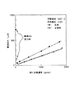
図2に、炭化水素濃度と出力の関係を示す。また、比較のためアノードとカソードとに共にPt電極を用いた従来のセンサの出力特性も合わせて示す。
本発明のセンサと従来センサとは、炭化水素濃度と検出出力とが良好な直線性を示す。炭化水素濃度が低い状態で酸素を5%混入したとき、従来センサでは、図2に併記するように、電極間の電流出力が急激に増加したが、しかし、本発明のセンサでは、酸素に起因した電流出力の増加がかなり抑えられていることがわかる。このことより、明らかに本発明の炭化水素センサは、従来のものと比べ良好に炭化水素への選択的応答性を示し、酸素混入時も高精度に検知可能であることが判る。
【0019】
この実施形態における酸素に不活性な金属材料によりカソードを形成すること、さらに、アノードとカソードとを異種の電極金属の組合せにすることは、以下の実施形態に示す他の手段においても併用することが好ましい。
【0020】
第二の実施形態は、本発明のセンサは、電解質層1の表面に形成されるカソード3の面積をアノード2の面積よりも相対的に小さくするものであり、これにより、カソード表面で酸素が解離される頻度を低下させ、電解質層中への酸素イオン伝導に起因する限界電流を相対的に少なくするものである。
【0021】
図3(A)に、固体電解質1のカソード3側から見たセンサの平面図を示すが、この例では電解質1の表面のカソード3の方形電極は、これに対面する電解質1の裏面のアノード2の方形電極よりも面積が縮小されている。なお図において29、30は電気的接続部である。本発明においては、アノード3に対するカソード2の電極面積の率は、30〜80%の範囲が適当であり、カソードの電極面積率30%未満では、炭化水素に対する検出電流が小さくなるので好ましくなく、80%越えると、酸素に起因する電流測定誤差の減少が改善されない。この電極面積率は、好ましくは、50〜70%とする。
【0022】
実施例2として、カソード面積を縮小したセンサの実施例を示すが、センサの構造は、固体電解質1に10mm×10mm厚さ0.45mmのBaCe0.8 Y 0.2 O 3−α 焼結体の電解質層に、アノード2とカソード3とに共に、白金皮膜を使用して構成し、実施例1と同様に、炭化水素の拡散律速孔を有するアノード室40をセラミック基板4とガラススペーサ41により作製した。アノード2とカソード3の形状は、図3(A)に示すような方形にパターン形成し、電極面積は、アノード2が0.36cm 2 に対してカソード3を0.25cm 2 として、カソード3側を小面積とした。
【0023】
前の実施例1と同様にして、被検ガスに、自動車の排ガスを用いて、カソード面積を縮小したセンサについて調べた炭化水素濃度と電流出力との関係を図4に示す。また、比較のため、PtアノードとPtカソードとを同じ面積にしたセンサの出力特性も併記した。従来センサでは、炭化水素濃度が低い状態で酸素が混入したとき、図4に示すように、電流出力が急激に上昇した。しかし、本発明のセンサでは、酸素に起因した電流出力はかなり抑えられていることがわかる。このことより、明らかに本発明の炭化水素センサが従来と比べ良好に応答し、酸素混入時も高精度に検知可能であることが証明された。
【0024】
なお、本実施例では、アノードとカソードとに電極面積の相違する白金電極を用いたが、両電極に、例えば、同じくAuを用いたものでも、PtとAuとの異種の組み合わせであっても同様の効果を確認している。
【0025】
このように、アノードに比してカソードの面積を低減するのは、酸素の検出電流への影響を減らすのには良いが、しかしながら、他方では、アノードからカソードに移動する水素イオンH+からみると、図3(B)に示すように、アノード2の周辺縁部から電解質層1を移動してカソード3に達する水素イオンは、電解質層1を厚み方向に対して斜交するように移動するので、電解質層中のその透過経路が長くなり、このことは、炭化水素検出の感度低下の原因となり得るという問題点が残る。
【0026】
このための方策は、カソード3の外形をアノード2の外形とはほぼ同じとして、カソード3をその面域に1つ以上の開口部30又は1つ以上の切欠き部31を形成して、カソード電極の面積を実質的に縮小することである。これにより、アノード2からのカソード3へのプロトンの透過経路が平均的に短くなり、炭化水素の感度低下を抑えることができる。このようなカソードは、細帯状の金属皮膜を使用して、図5(A)のように開口部30を設けて格子状としたり、図5(B)のように切欠き部31を設けて櫛状ないし魚骨状とする形状が好ましく採用される。
【0027】
実施例3として、カソードの形状を細帯金属皮膜により格子状にした限界電流式炭化水素センサの事例を、以下に示す。まず、印刷機を用い、電解質層1の表面に、図5(A)に示すように、カソード3を、Ptペーストを使用して面域に16個の開口部30を形成して格子状パターンとし、カソード以外のセンサの要素の構成は、実施例1と同様にした。この場合には、カソードの面積は、アノードの面積の35%であった。
【0028】
このセンサを使用して、実施例2と同様にして、被検ガスに自動車の排ガスを用いて、炭化水素濃度と検出電流の関係を調べた。図6に、炭化水素濃度と出力の関係を示す。また、比較のため従来の同じ面積のPt電極を用いたセンサの出力特性も合わせて示す。従来センサでは、炭化水素濃度が低い状態で酸素が混入したとき、図に示すように、出力が急激に上昇した。しかし、本発明の格子状カソードを用いたセンサは、いずれも酸素混入時も出力が抑えられ、従来と比べ、酸素混合排ガス中の炭化水素を高精度に検出することが可能であることがわかった。
【0029】
第3の実施形態は、本発明の炭化水素センサは、カソード側に酸素拡散律速手段を設けて、雰囲気中から酸素がカソード側に移行する速度を律速するセンサを含む。酸素拡散律速手段には、好ましくは、固体電解質層1の表面をカソード3上に空間を設けて覆うセラミック基板7を設け、該セラミック基板7と固体電解質層1との間の拡散律速孔72を形成して成るものが採用される。
他の酸素拡散律速手段には、電解質層1上のカソード面域上に直接に若しくは間接に被覆された連通気孔性のセラミック層も利用される。
【0030】
酸素拡散律速手段の例として、図7に、限界電流式炭化水素センサの構造を示すが、センサは、固体電解質層1として、この電解質層1の表面に、アノード2とカソード3とを電極により形成し、この例では、酸素拡散律速手段として、カソード3側に、セラミック基板7とガラススペーサ71よりカソード室70を形成し、セラミック基板7と電解質層1との間に雰囲気に連通する小孔を設けて酸素拡散律速孔72とされている。
そして、アノード2側には、従来と同様に、炭化水素拡散律速手段として、セラミック基板4とガラススペーサ41によりアノード室40を形成して、セラミック基板4と電解質層1との間の小孔42をもって炭化水素の拡散律速孔42としてある。
【0031】
酸素拡散律速手段については、カソード3側では、雰囲気中の酸素は、セラミック基板7とガラススペーサ71で形成された酸素拡散律速孔72を通り、カソード3での電解により酸素イオンに解離し、固体電解質層1中を伝導し、アノードで酸素ガスとして放出される。しかしながら、このときの酸素流入速度は酸素拡散律速孔72により制限されるので、固体電解質層1中を移動する酸素イオン量が規制され、電極間に流れる電流のうち酸素イオンに起因する電流を最小に抑えることができ、酸素による検出電流の誤差を最小限にすることができるのである。一方、炭化水素については、アノード室40で電離された水素イオンは、上述のように、固体電解質層を移動して、カソード室内のカソードで気体水素になり、気体水素は酸素に比して拡散係数が大きいので、酸素拡散律速孔を通過して雰囲気中に放出され、酸素拡散律速手段を設けても炭化水素の測定の支障にはならない。
【0032】
実施例4として、電解質層1に、外形が10mm×10mmで厚さ0.45mmのBaCe0.8 Dy0.2 O 3−α 焼結体を利用し、アノード2とカソード3とを白金電極により形成し、図7に示すように、カソード側に酸素拡散律速手段としてカソード室70と酸素拡散律速孔72を形成した炭化水素センサについて、その特性を、自動車の排ガス中で調べた。測定条件は、素子温度約600℃、印加電圧0.6Vで行った。
【0033】
図8に、酸素拡散律速手段を形成した場合の炭化水素濃度と出力の関係を示す。また、比較のためカソード側に酸素拡散律速手段を備えない従来のセンサの出力特性も併せて示す。従来センサでは、炭化水素濃度が低い状態で雰囲気中に酸素が混入したとき、図8に示すように、出力が急激に上昇して、大きな誤差となっているが、本発明のセンサでは、酸素混入によっても、酸素拡散律速手段により電流出力変動はかなり低く抑えられており、しかも、炭化水素濃度に対する出力電流の感度特性は、従来センサと全く同じであることがわかる。このことから、明らかに本発明の炭化水素センサが、酸素混入時も高精度に検知可能であることが証明された。
【0034】
第4の実施形態において、本発明は、前記カソードへの酸素の移動を規制する酸素吸収手段を備えたものである。酸素吸収手段は、カソード側に存在する酸素を吸収させる機能を有するものであり、酸素吸収手段としては、電解質層1上で、カソード3を覆って付着された多孔質の酸素吸収層9が利用される。酸素吸収層9は、例えば、酸化還元容易な酸化物の多孔体が挙げられる。このような酸化物としては、セリウム酸化物が好ましく利用される。また、他の酸素吸収層9としては、アルミナ系のモレキュラシーブも使用可能である。このような酸素吸収手段は、雰囲気中の酸素がカソードへ移動する際に酸化物として吸着固定し、カソードに到達する酸素量を低減し、同時に、H + イオンによりカソードで発生した気体水素は、多孔性の酸素吸収手段を透過して、雰囲気中に放散されるので、炭化水素の測定の障害にはならない。
【0035】
本発明のセンサの構造を図9に例示するが、固体電解質層1の表面には、アノード2とカソード3とが形成され、カソード3にはその上面に酸素を吸収させるセリウム酸化物層が塗布積層されて多孔質の酸素吸収層9とされており、他方のアノード2側には、従来のものと同様に、炭化水素拡散律速手段として、セラミック基板4とガラススペーサ41によりアノード室40が形成され、セラミック基板4と固体電解質層1間に拡散律速孔42が形成されている。
【0036】
実施例5として酸素吸収手段を利用した例を以下に示すが、図9において、電解質層1に、外形が10mm×10mmで厚さ0.45mmのBaCe0.8 Y 0.2 O 3−α 焼結体を使用し、アノード2とカソード3とを同じ面積の白金電極により形成し、アノード2側の炭化水素律速手段を形成し、カソード2側には、カソード3上にセリウム酸化物粉末を塗着して焼結した酸素吸収層9を形成被覆した。この炭化水素センサの特性を、自動車の排ガス中で調べた。図10に、炭化水素濃度と出力の関係を示す。また、図10には、比較のために、酸素吸収手段を設けない点を除いて同様の構成の炭化水素センサについての出力特性も合わせて示す。
【0037】
従来センサでは、炭化水素濃度が低い状態で酸素が混入したとき、図10に示すように、センサの電流出力が急激に上昇するが、本発明のセンサでは、酸素混入時の出力がかなり抑えられていることがわかる。このことより、明らかに酸素吸収手段を備えた本発明の炭化水素センサが、従来と比べ良好に応答し、酸素混入時も高精度に検知可能であることが判る。
【0038】
第5の実施形態について、本発明の炭化水素センサは、カソード側に酸素の燃焼消費を促進する酸素消費手段を有するものが含まれる。酸素消費手段は、カソード側に存在する酸素を炭化水素と燃焼反応させて消費させる機能を有するものである。酸素消費手段には、酸素と炭化水素との反応を促進させる触媒として、Pt、Rh、Pd、Ruなどを使用することができる。
【0039】
酸素消費手段は、カソード上3に、セラミック基板7とガラススペーサ71とによりカソード室70を雰囲気に連通可能に形成し、カソード室内のセラミック基板7とガラススペーサ71の内面に触媒層8を塗着した構造のものが採用できる。酸素消費手段としての白金等の触媒を含む多孔質の触媒層8などは、塗膜焼成法、溶射法その他、真空蒸着法、スパッタ法などの物理的生成法や、CVD法などの化学的生成法が広く使用される。触媒層8の触媒は、カソード3には直接接触せずに、カソード室70に入ってくる酸素と、同時に入ってくる炭化水素との燃焼反応を促進させて、酸素を酸化消費させ、カソード3に移行する酸素量を極力低減するものである。
【0040】
また、その他の酸素消費手段としては、カソード3の全面を覆う適当な絶縁性セラミック質の連通気孔性の担持体に前記の金属触媒を含有担持させたものでもよい。
【0041】
本発明のセンサの構造を図11に示すが、固体電解質層1の表面に、アノード2とカソード3とが形成され、炭化水素の拡散律速手段が、セラミック基板4とガラス5によりアノード側に形成されている。酸素消費手段には、図11に示すように、カソード3側の電解質層1の表面にカソードを覆う形で、Ptの触媒層8が形成されている。この触媒層8は、多孔質でガスの移動は自由にできるようにされて、Ptの触媒作用により、近傍の酸素は、炭化水素と反応し燃焼する。このようにして、雰囲気から移動してきたカソード室70の酸素は、カソードに到達する前に、取り除かれることになる。
なお、小孔74は、同時に、酸素拡散律速孔72を兼用させて、カソード室70を含めた酸素消費手段を、前記の酸素拡散律速手段を兼ねさせることもできる。
【0042】
実施例6として、酸素消費手段を備えた例を以下に示すが、固体電解質1として外形10mm×10mmで厚さ0.45mmのBaCe0.8 Gd0.2 O 3−α 焼結体を使用し、アノード2とカソード3とに同じ面積のPt電極を用いて構成し、カソード3には酸素消費手段として、セラミック基板7とガラススペーサ71により雰囲気と連通可能な小孔74を備えたカソード室70が形成され、セラミック基板7の内面と、カソード室70に連通する当該開口部72に多孔質の白金の触媒層8で被覆した。
また、アノード側には、従来と同様にセラミック基板4とガラススペーサ41によりアノード室40と炭化水素拡散律速孔42から成る炭化水素拡散律速手段を構成した。
【0043】
このセンサの炭化水素検知特性を、前実施例と同様に、自動車の排ガス中で調べた。図12に、炭化水素濃度と出力の関係を示す。また、比較のため、カソード側に酸素消費手段を備えない従来のセンサの出力特性も合わせて示す。従来センサでは、炭化水素濃度が低い状態で酸素が混入したとき、図12に示すように、出力が急激に上昇するが、本発明のセンサでは、酸素混入に伴う出力はかなり抑えられていることがわかる。このことより、明らかに本発明の炭化水素センサが従来と比べ良好に応答し、酸素混入時も高精度に炭化水素の検知が可能であることが判る。
【0044】
【発明の効果】
本発明は、バリウムセリウム系酸化物を固体電解質に利用した前記の限界電流式炭化水素センサにおいて、雰囲気中の酸素が移行して解離されるカソード側に、酸素の移行または解離を阻止または低減する手段を構成したので、雰囲気からのカソードにおける酸素イオン濃度を低減して、検出出力に酸素イオンを起源とする誤差電流が発生することのないように、低減ないし阻止し得て、炭化水素センサの精度と信頼性を高めることができる。
【0045】
また、酸素に不活性な金属より成るカソードの採用や、アノードより小面積としたカソードの採用により、特に、容易に且つ低コストで炭化水素センサを製造することが可能となる。
【0046】
さらに、前記カソードに酸素拡散律速手段、酸素吸収手段又は、酸素消費手段を備えることにより、カソードに到達する前に実質的に酸素を除去できるので、酸素共存下での炭化水素測定が、被測定雰囲気中に存在する酸素の影響を実質的に受けることのなく、高精度に実行することができる。
【図面の簡単な説明】
【図1】 従来のバリウムセリウム酸化物系電解質層を使用した限界電流式の炭化水素センサの概念的に示す縦断面図。
【図2】 カソードに銀電極を利用した炭化水素センサにおける炭化水素濃度とセンサ電流出力との関係を示す図。
【図3】 実施例に係るアノードとカソードの電極形状を示す固体電解質層の平面図(A)とその部分縦断面(B)。
【図4】 カソードを小面積とした炭化水素センサにおける炭化水素濃度とセンサ電流出力とのの関係を示す図。
【図5】 実施例に係るカソードの電極形状を示す平面図(A,B)。
【図6】 実施例における格子状カソードを使用した限界電流式炭化水素センサにおける図2同様図。
【図7】 カソード側に酸素拡散律速手段を設けた限界電流式炭化水素センサの模式的断面図。
【図8】 実施例にかかる酸素拡散律速手段を設けた炭化水素センサにおける図2同様図。
【図9】 カソード側に酸素消費手段を設けた限界電流式炭化水素センサの模式的断面図。
【図10】 実施例に係る酸素燃焼消費手段を設けた炭化水素センサにおける炭化水素濃度とセンサ電流出力との関係を示す図。
【図11】 カソード側に酸素吸収手段を設けた限界電流式炭化水素センサの模式的断面図。
【図12】 実施例に係る酸素吸収手段を設けた炭化水素センサの炭化水素濃度とセンサ電流出力との関係を示す図。
【符号の説明】
1 固体電解質層
2 アノード
3 カソード
4 セラミック基板
40 アノード室
42 炭化水素拡散律速孔
70 カソード室
72 酸素拡散律速孔
8 酸素消費層
9 酸素吸収層[0001]
BACKGROUND OF THE INVENTION
The present invention relates to a limiting current type hydrocarbon sensor used for detection and concentration measurement of hydrocarbons in a temperature range from room temperature to high temperature (800 ° C.), and more particularly, detection of hydrocarbon gas in a living environment, for automobiles The present invention relates to improvements in hydrocarbon sensors that can be used for combustion control (lean burn) of combustion equipment and catalyst deterioration monitoring by detecting residual hydrocarbons in exhaust gas from engines, stoves, catalytic combustion equipment, etc.
[0002]
[Prior art]
The present inventors have already proposed a limiting current type (constant potential electrolytic type) hydrocarbon sensor using a barium cerium-based oxide exhibiting high proton conductivity as a solid electrolyte.Wish7-285800). A sensor using this electrolyte responds well to a small amount of hydrocarbons in the atmosphere, and has the ability to linearly detect hydrocarbons in the concentration range of several ppm to several percent in the atmosphere.
[0003]
As shown in FIG. 1, the general structure of this sensor is that a barium cerium oxide (BaCeOO) is formed on a
[0004]
When the sensor is used, a constant potential E is applied between the
[0005]
Sensors that perform quantitative detection of hydrocarbon concentration in combustion exhaust gas from internal combustion engines such as the above-mentioned automobile engines and other combustion equipment have selectivity only for hydrocarbons. Even so, it is required that the hydrocarbons in the atmosphere have high sensitivity and high data reliability. At the same time, such a sensor is also required to be small in size, easy and easy to manufacture, and low in manufacturing cost. For such applications, the above-mentioned limiting current type hydrocarbon sensor using barium-cerium-based oxide has high proton mobility, large detection current signal, and good linearity with respect to hydrocarbon concentration. Is widely expected.
[0006]
[Problems to be solved by the invention]
Conventional sensors that use barium cerium-based oxides as solid electrolytes have good responsiveness to hydrocarbons, but when oxygen gas is present in the atmosphere, the sensor is also sensitive to this oxygen gas, The detection current between the electrodes includes a current corresponding to oxygen gas, which causes a large measurement error. In particular, when the hydrocarbon concentration is small and the oxygen concentration is high, the current output from the sensor is large, which makes it impossible to detect the hydrocarbon concentration. Such variations in the atmospheric composition can often occur in the exhaust gas of an automobile engine due to changes in the fuel-air mixture ratio and the rotational speed. As described above, in the atmosphere in which the atmosphere to be measured coexists with the hydrocarbon gas and the oxygen gas, a detection error due to oxygen occurs in the sensor, and there is a problem that the hydrocarbon concentration cannot be detected with high accuracy.
[0007]
In view of the above problems, the present invention provides a limit current sensor that uses barium cerium-based oxide as a solid electrolyte, is insensitive to oxygen even in an oxygen-containing atmosphere, and accurately detects hydrocarbons, or its It is an object of the present invention to provide a hydrocarbon sensor capable of accurately measuring the concentration.
[0008]
[Means for Solving the Problems]
In the limiting current type hydrocarbon sensor using barium cerium oxide as a solid electrolyte, the present invention prevents or reduces oxygen dissociation or migration on the cathode side where oxygen in the atmosphere migrates and ion dissociates. By providing the means for reducing the amount of oxygen ions at the cathode, the generation of error current originating from oxygen ion conduction is reduced or prevented.
[0009]
Barium and cerium-based oxides also have oxygen ion conductivity due to fluctuations and malfunctions in the current value between electrodes when oxygen coexists in the atmosphere.RutaAs for the conventional sensor, the cathode side is H2 In order to dissipate gas, it is necessary to expose the atmosphere to be measured. For this reason, oxygen in the atmosphere to be measured moves to the cathode surface and dissociates into oxygen ions, and the oxygen ions move to the anode side in the solid electrolyte. As a result, the current originating from oxygen at the electrode is added to the detection output of the hydrocarbon.
[0010]
The present invention prevents the generation of error current by suppressing the generation of oxygen ions at the cathode even when the sensor is in an oxygen-containing atmosphere.
To achieve this, the present invention is more specifically classified into two means.
The first means is a means for directly preventing or reducing oxygen dissociation at the cathode of oxygen gas, which includes a cathode made of a metal inert to oxygen and a cathode shape having a smaller area than the anode. Is adopted.
[0011]
In the present invention, the second means includes an oxygen suppressing means for suppressing oxygen transfer to the cathode as described below. For this, an oxygen diffusion rate controlling means for controlling the diffusion movement of oxygen to the cathode, an oxygen absorption means for regulating the movement of oxygen to the cathode, or an oxygen consumption means for promoting the combustion consumption of oxygen on the cathode side is adopted. The
[0012]
DETAILED DESCRIPTION OF THE INVENTION
Details of the present invention will be described below with reference to the drawings. Structurally, there are many places common to FIG. 1 showing the conventional example, and explanation will be given using FIG. In addition, since there are many places where the constituent elements are common, common elements will be described with the same numbers. Regarding the structure of the limiting current type hydrocarbon sensor of the present invention, the
In general formula, BaCe1-XMX O 3 [0.16≦X≦ 0.23] can be used, and for R, rare earth metals other than Ce, such as Y, Gd, Dy, Sm, and Tb, are used.
[0013]
The
Further, on the
[0014]
Further, a heater 6 is attached to the sensor, for example, on the ceramic substrate 4, and the entire sensor including the
[0015]
In the first embodiment, the hydrocarbon sensor of the present invention is such that the cathode electrode material is formed of a metal material inert to oxygen. Here, as the metal inert to oxygen, an oxygen inert metal is preferably used as compared with Pt normally used for the electrode metal of the
[0016]
The combination of the electrode metal of the anode and the cathode can be a combination of Ag and Ag, for example. Another combination of anode and cathode electrode metals may be a combination of different metals, for example, a combination of anode Pt and cathode Cu, anode Pt and cathode Ag, Pd and Au, or the like. Further, the electrode metal may be a mixture of Pd and Pt or a mixture of Ag and Au.
[0017]
As Example 1, CoveredAn example is shown in which the detection characteristics of a sensor using an automobile exhaust gas as the detection gas, Pt as the anode, and Ag as the cathode are examined.
BaCe as barium cerium oxide0. 8 Gd0. 2 O 3 setThe
The measurement of hydrocarbons is carried out by exposing the sensor to the exhaust gas at an applied voltage of 0.6 V between the
[0018]
FIG. 2 shows the relationship between the hydrocarbon concentration and the output. For comparison, the output characteristics of a conventional sensor using a Pt electrode for both the anode and the cathode are also shown.
The sensor of the present invention and the conventional sensor show good linearity in hydrocarbon concentration and detection output. When oxygen was mixed at 5% with a low hydrocarbon concentration, the current output between the electrodes rapidly increased as shown in FIG. 2 in the conventional sensor. However, in the sensor of the present invention, it is caused by oxygen. It can be seen that the increase in the current output is considerably suppressed. This clearly shows that the hydrocarbon sensor of the present invention shows a selective response to hydrocarbons better than the conventional one, and can be detected with high accuracy even when oxygen is mixed.
[0019]
In this embodiment, forming the cathode from a metal material inert to oxygen, and further combining the anode and the cathode with different electrode metals can also be used in other means shown in the following embodiments. Is preferred.
[0020]
In the second embodiment, the sensor according to the present invention is such that the area of the
[0021]
FIG. 3A shows a plan view of the sensor viewed from the
[0022]
As Example 2, MosquitoAn example of a sensor with a reduced sword area is shown. The structure of the sensor is a BaCe 10 mm × 10 mm 0.45 mm thick in the
[0023]
FIG. 4 shows the relationship between the hydrocarbon concentration and the current output in the same manner as in the previous Example 1, which was examined for a sensor in which the exhaust gas of an automobile was used as the test gas and the cathode area was reduced. For comparison, the output characteristics of a sensor in which the Pt anode and the Pt cathode have the same area are also shown. In the conventional sensor, when oxygen is mixed in a state where the hydrocarbon concentration is low, the current output rapidly increases as shown in FIG. However, in the sensor of the present invention, it can be seen that the current output due to oxygen is considerably suppressed. This clearly proves that the hydrocarbon sensor of the present invention responds better than before, and can be detected with high accuracy even when oxygen is mixed.
[0024]
In this embodiment, platinum electrodes having different electrode areas are used for the anode and the cathode. For example, Au may be used for both electrodes, or a different combination of Pt and Au. Similar effects have been confirmed.
[0025]
Thus, reducing the area of the cathode compared to the anode is good for reducing the influence of oxygen on the detection current,However,On the other hand, hydrogen ions H moving from the anode to the cathode+As seen from FIG. 3B, the hydrogen ions that move from the peripheral edge of the
[0026]
For this purpose, the outer shape of the
[0027]
As Example 3, an example of a limiting current type hydrocarbon sensor in which the shape of the cathode is made into a lattice by a thin metal film is shown below. First, using a printing machine, a
[0028]
Using this sensor, the relationship between the hydrocarbon concentration and the detected current was examined in the same manner as in Example 2, using the exhaust gas of an automobile as the test gas. FIG. 6 shows the relationship between the hydrocarbon concentration and the output. For comparison, the output characteristics of a sensor using a conventional Pt electrode having the same area are also shown. In the conventional sensor, when oxygen was mixed in a state where the hydrocarbon concentration was low, the output increased rapidly as shown in the figure. However, all the sensors using the grid-like cathode of the present invention can suppress the output even when oxygen is mixed, and it is understood that hydrocarbons in the oxygen mixed exhaust gas can be detected with higher accuracy than before. It was.
[0029]
In the third embodiment, the hydrocarbon sensor of the present invention includes a sensor that provides oxygen diffusion rate limiting means on the cathode side to limit the rate at which oxygen moves from the atmosphere to the cathode side. The oxygen diffusion rate controlling means is preferably provided with a
As another oxygen diffusion rate limiting means, a continuous air-permeable ceramic layer coated directly or indirectly on the cathode surface area on the
[0030]
As an example of the oxygen diffusion rate limiting means, FIG. 7 shows the structure of a limiting current type hydrocarbon sensor. The sensor is a
On the
[0031]
As for the oxygen diffusion rate limiting means, on the
[0032]
As Example 4, BaCe having an outer shape of 10 mm × 10 mm and a thickness of 0.45 mm was formed on the
[0033]
FIG. 8 shows the relationship between the hydrocarbon concentration and the output when the oxygen diffusion rate limiting means is formed. For comparison, the output characteristics of a conventional sensor that does not have oxygen diffusion rate limiting means on the cathode side are also shown. In the conventional sensor, when oxygen is mixed in the atmosphere in a state where the hydrocarbon concentration is low, as shown in FIG. 8, the output increases rapidly, resulting in a large error. It can be seen that, even by mixing, the current output fluctuation is suppressed to a very low level by the oxygen diffusion rate limiting means, and the sensitivity characteristic of the output current with respect to the hydrocarbon concentration is exactly the same as that of the conventional sensor. This clearly proves that the hydrocarbon sensor of the present invention can be detected with high accuracy even when oxygen is mixed.
[0034]
In a fourth embodiment, the present invention includes an oxygen absorbing means for restricting the movement of oxygen to the cathode. The oxygen absorbing means has a function of absorbing oxygen existing on the cathode side. As the oxygen absorbing means, a porous oxygen absorbing layer 9 attached on the
[0035]
The structure of the sensor of the present invention is illustrated in FIG. 9. An
[0036]
As Example 5acidAn example using the element absorbing means is shown below. In FIG. 9, the
[0037]
In the conventional sensor, when oxygen is mixed in a state where the hydrocarbon concentration is low, as shown in FIG. 10, the current output of the sensor increases rapidly, but in the sensor of the present invention, the output at the time of oxygen mixing is considerably suppressed. You can see that This clearly shows that the hydrocarbon sensor of the present invention having the oxygen absorbing means responds better than before and can detect with high accuracy even when oxygen is mixed.
[0038]
Regarding the fifth embodiment, the hydrocarbon sensor of the present invention includes one having oxygen consuming means for promoting the combustion consumption of oxygen on the cathode side. The oxygen consuming means has a function of consuming the oxygen present on the cathode side through combustion reaction with hydrocarbons. As the oxygen consuming means, Pt, Rh, Pd, Ru, or the like can be used as a catalyst for promoting the reaction between oxygen and hydrocarbons.
[0039]
The oxygen consuming means forms a
[0040]
As another oxygen consuming means, the above metal catalyst may be supported on an appropriate insulating ceramic continuous air-permeable support covering the entire surface of the
[0041]
The structure of the sensor of the present invention is shown in FIG. 11, where the
The small hole 74 also includes the
[0042]
As Example 6, an example provided with oxygen consuming means is shown below. As
Further, on the anode side, a hydrocarbon diffusion control means comprising an
[0043]
The hydrocarbon detection characteristics of this sensor were examined in the exhaust gas of automobiles as in the previous example. FIG. 12 shows the relationship between the hydrocarbon concentration and the output. For comparison, the output characteristics of a conventional sensor that does not include oxygen consuming means on the cathode side are also shown. In the conventional sensor, when oxygen is mixed in a state where the hydrocarbon concentration is low, the output increases rapidly as shown in FIG. 12, but in the sensor of the present invention, the output accompanying oxygen mixing is considerably suppressed. I understand. This clearly shows that the hydrocarbon sensor of the present invention responds better than before and can detect hydrocarbons with high accuracy even when oxygen is mixed.
[0044]
【The invention's effect】
In the limiting current hydrocarbon sensor using barium cerium oxide as a solid electrolyte, the present invention prevents or reduces oxygen migration or dissociation on the cathode side where oxygen in the atmosphere migrates and dissociates. Since the means is configured, the oxygen ion concentration at the cathode from the atmosphere can be reduced to reduce or prevent an error current originating from oxygen ions from being generated in the detection output. Can increase accuracy and reliabilityRu.
[0045]
In addition, the adoption of a cathode made of a metal inert to oxygen, or the adoption of a cathode having a smaller area than the anode makes it possible to manufacture a hydrocarbon sensor particularly easily and at low cost.
[0046]
Furthermore, by providing the cathode with oxygen diffusion rate limiting means, oxygen absorbing means, or oxygen consuming means, it is possible to substantially remove oxygen before reaching the cathode, so hydrocarbon measurement in the presence of oxygen can be measured. The process can be executed with high accuracy without being substantially affected by the oxygen present in the atmosphere.
[Brief description of the drawings]
FIG. 1 is a longitudinal sectional view conceptually showing a limiting current type hydrocarbon sensor using a conventional barium cerium oxide based electrolyte layer.
FIG. 2 shows the hydrocarbon concentration and sensor current output in a hydrocarbon sensor using a silver electrode for the cathode.No sekiFIG.
FIG. 3 is a plan view (A) of a solid electrolyte layer showing electrode shapes of an anode and a cathode according to an embodiment and a partial longitudinal section (B) thereof.
FIG. 4 is a graph showing a relationship between a hydrocarbon concentration and a sensor current output in a hydrocarbon sensor having a small cathode area.
FIG. 5 is a plan view (A, B) showing the electrode shape of the cathode according to the example.
6 is a view similar to FIG. 2 in a limiting current type hydrocarbon sensor using a grid-like cathode in an example. FIG.
FIG. 7 is a schematic cross-sectional view of a limiting current type hydrocarbon sensor provided with oxygen diffusion rate limiting means on the cathode side.
FIG. 8 is a view similar to FIG. 2 in a hydrocarbon sensor provided with oxygen diffusion rate-limiting means according to an embodiment.
FIG. 9 is a schematic cross-sectional view of a limiting current type hydrocarbon sensor provided with oxygen consuming means on the cathode side.
FIG. 10 is a view showing a relationship between a hydrocarbon concentration and a sensor current output in a hydrocarbon sensor provided with an oxyfuel combustion consumption unit according to an example.
FIG. 11 is a schematic cross-sectional view of a limiting current type hydrocarbon sensor provided with oxygen absorbing means on the cathode side.
FIG. 12 is a diagram showing the relationship between the hydrocarbon concentration and the sensor current output of a hydrocarbon sensor provided with an oxygen absorbing means according to an example.
[Explanation of symbols]
1 Solid electrolyte layer
2 Anode
3 Cathode
4 Ceramic substrate
40 Anode chamber
42 Hydrocarbon diffusion controlled pores
70 Cathode chamber
72 Oxygen diffusion rate limiting hole
8 Oxygen consumers
9 Oxygen absorption layer
Claims (10)
Priority Applications (1)
| Application Number | Priority Date | Filing Date | Title |
|---|---|---|---|
| JP10588497A JP3841513B2 (en) | 1997-04-23 | 1997-04-23 | Hydrocarbon sensor |
Applications Claiming Priority (1)
| Application Number | Priority Date | Filing Date | Title |
|---|---|---|---|
| JP10588497A JP3841513B2 (en) | 1997-04-23 | 1997-04-23 | Hydrocarbon sensor |
Publications (2)
| Publication Number | Publication Date |
|---|---|
| JPH10300718A JPH10300718A (en) | 1998-11-13 |
| JP3841513B2 true JP3841513B2 (en) | 2006-11-01 |
Family
ID=14419366
Family Applications (1)
| Application Number | Title | Priority Date | Filing Date |
|---|---|---|---|
| JP10588497A Expired - Lifetime JP3841513B2 (en) | 1997-04-23 | 1997-04-23 | Hydrocarbon sensor |
Country Status (1)
| Country | Link |
|---|---|
| JP (1) | JP3841513B2 (en) |
Cited By (1)
| Publication number | Priority date | Publication date | Assignee | Title |
|---|---|---|---|---|
| KR20160128130A (en) | 2015-04-28 | 2016-11-07 | 주식회사 에코메트론 | Sensor of sphere shape for identifying hydrocarbones, method for manufacturing and use thereof |
Families Citing this family (7)
| Publication number | Priority date | Publication date | Assignee | Title |
|---|---|---|---|---|
| KR100319947B1 (en) | 1998-04-06 | 2002-01-09 | 마츠시타 덴끼 산교 가부시키가이샤 | Hydrocarbon sensor |
| JP4241993B2 (en) | 1999-04-01 | 2009-03-18 | パナソニック株式会社 | Hydrocarbon sensor |
| JP2000297628A (en) | 1999-04-16 | 2000-10-24 | Honda Motor Co Ltd | Deterioration determining device for exhaust emission purification device of internal combustion engine |
| JP2000297630A (en) | 1999-04-16 | 2000-10-24 | Honda Motor Co Ltd | Deterioration determining device for exhaust emission purification device of internal combustion engine |
| EP1199561A1 (en) | 2000-10-16 | 2002-04-24 | Matsushita Electric Industrial Co., Ltd. | Hydrocarbon sensor and method for producing the same |
| JP4739716B2 (en) * | 2003-09-29 | 2011-08-03 | ローベルト ボツシユ ゲゼルシヤフト ミツト ベシユレンクテル ハフツング | Sensor element |
| JP5707180B2 (en) * | 2011-03-07 | 2015-04-22 | 株式会社日本自動車部品総合研究所 | Gas sensor element and gas concentration detection method |
-
1997
- 1997-04-23 JP JP10588497A patent/JP3841513B2/en not_active Expired - Lifetime
Cited By (1)
| Publication number | Priority date | Publication date | Assignee | Title |
|---|---|---|---|---|
| KR20160128130A (en) | 2015-04-28 | 2016-11-07 | 주식회사 에코메트론 | Sensor of sphere shape for identifying hydrocarbones, method for manufacturing and use thereof |
Also Published As
| Publication number | Publication date |
|---|---|
| JPH10300718A (en) | 1998-11-13 |
Similar Documents
| Publication | Publication Date | Title |
|---|---|---|
| KR100347643B1 (en) | Electrochemical Sensors for Determining Oxygen Concentrations in Gas Mixtures | |
| US6136170A (en) | Exhaust gas sensor and system thereof | |
| EP0853762B1 (en) | Gas sensor and manufacturing process thereof | |
| JP3311218B2 (en) | Hydrocarbon sensor | |
| JP3128114B2 (en) | Nitrogen oxide detector | |
| KR100319947B1 (en) | Hydrocarbon sensor | |
| JP3933697B2 (en) | Sensor for determining the concentration of oxidizable components in a gas mixture | |
| JP4162262B2 (en) | Sensor for measuring the concentration of oxidizable components in a gas mixture | |
| JP3841513B2 (en) | Hydrocarbon sensor | |
| JP4241993B2 (en) | Hydrocarbon sensor | |
| JP2006133039A (en) | Nitrogen oxide sensor | |
| JPH09269307A (en) | Gas sensor | |
| JP2007219791A (en) | Fire alarm | |
| JP3556790B2 (en) | Exhaust gas sensor and exhaust gas sensor system | |
| JP3075070B2 (en) | Carbon monoxide gas sensor | |
| US20110210013A1 (en) | Selective gas sensor device and associated method | |
| JP2000028573A (en) | Hydrocarbon gas sensor | |
| KR101133267B1 (en) | NOx gas sensor | |
| JPH0829390A (en) | Carbon monoxide sensor | |
| JP3795227B2 (en) | Hydrocarbon sensor | |
| JP3511747B2 (en) | Gas sensor | |
| JP2002031619A (en) | Nitrous oxide gas sensor | |
| JP3326899B2 (en) | Thin film air-fuel ratio sensor | |
| JPH0894576A (en) | Gas sensor and its manufacture | |
| JPH1123518A (en) | Carbon monoxide gas detecting element |
Legal Events
| Date | Code | Title | Description |
|---|---|---|---|
| A521 | Written amendment |
Free format text: JAPANESE INTERMEDIATE CODE: A523 Effective date: 20040330 |
|
| A621 | Written request for application examination |
Free format text: JAPANESE INTERMEDIATE CODE: A621 Effective date: 20040330 |
|
| A977 | Report on retrieval |
Free format text: JAPANESE INTERMEDIATE CODE: A971007 Effective date: 20051005 |
|
| A131 | Notification of reasons for refusal |
Free format text: JAPANESE INTERMEDIATE CODE: A131 Effective date: 20051101 |
|
| A521 | Written amendment |
Free format text: JAPANESE INTERMEDIATE CODE: A523 Effective date: 20051206 |
|
| TRDD | Decision of grant or rejection written | ||
| A01 | Written decision to grant a patent or to grant a registration (utility model) |
Free format text: JAPANESE INTERMEDIATE CODE: A01 Effective date: 20060801 |
|
| A61 | First payment of annual fees (during grant procedure) |
Free format text: JAPANESE INTERMEDIATE CODE: A61 Effective date: 20060808 |
|
| R150 | Certificate of patent or registration of utility model |
Free format text: JAPANESE INTERMEDIATE CODE: R150 |
|
| FPAY | Renewal fee payment (event date is renewal date of database) |
Free format text: PAYMENT UNTIL: 20090818 Year of fee payment: 3 |
|
| FPAY | Renewal fee payment (event date is renewal date of database) |
Free format text: PAYMENT UNTIL: 20100818 Year of fee payment: 4 |
|
| FPAY | Renewal fee payment (event date is renewal date of database) |
Free format text: PAYMENT UNTIL: 20110818 Year of fee payment: 5 |
|
| FPAY | Renewal fee payment (event date is renewal date of database) |
Free format text: PAYMENT UNTIL: 20110818 Year of fee payment: 5 |
|
| FPAY | Renewal fee payment (event date is renewal date of database) |
Free format text: PAYMENT UNTIL: 20120818 Year of fee payment: 6 |
|
| FPAY | Renewal fee payment (event date is renewal date of database) |
Free format text: PAYMENT UNTIL: 20130818 Year of fee payment: 7 |
|
| EXPY | Cancellation because of completion of term |