JP3841493B2 - Construction method of viaduct using PCa concrete member - Google Patents
Construction method of viaduct using PCa concrete memberInfo
- Publication number
- JP3841493B2 JP3841493B2 JP25089296A JP25089296A JP3841493B2 JP 3841493 B2 JP3841493 B2 JP 3841493B2 JP 25089296 A JP25089296 A JP 25089296A JP 25089296 A JP25089296 A JP 25089296A JP 3841493 B2 JP3841493 B2 JP 3841493B2
- Authority
- JP
- Japan
- Prior art keywords
- pca
- column
- projecting
- slab
- viaduct
- Prior art date
- Legal status (The legal status is an assumption and is not a legal conclusion. Google has not performed a legal analysis and makes no representation as to the accuracy of the status listed.)
- Expired - Fee Related
Links
Images


Description
【0001】
【発明の属する技術分野】
本発明は、鉄筋コンクリート製の高架橋を、柱、梁、スラブにプレキャスト(以下、PCaと略称する)コンクリート部材を用いて構築する技術に関するものである。
【0002】
【従来の技術】
鉄筋コンクリート製のビームスラブ型の高架橋は、図14及び図15に示すように、地盤G上の基礎梁101と、この基礎梁101上にその延長方向へ一定の間隔で並んで設けられた左右の柱102と、この柱102上に架設され左右両側に張り出し部103aを有するスラブ103とからなり、このスラブ103の下面に、前記左右の柱102の各列方向に延在された互いに平行な一対の縦梁103bと、両端が各柱102の上端位置で前記縦梁103b,103bに直交した横梁103cが形成された構成を有する。このようなビームスラブ型の高架橋の施工法としては、コンクリートの現場打ちによる方法のほか、PCaコンクリート部材を用いる方法がある。
【0003】
図16乃至図19は、PCaコンクリート部材を用いて上述の構造のビームスラブ型高架橋を構築する典型的な従来工法を示すものである。すなわちこの従来工法においては、まず図16に示すように、所要の深さに掘り下げた地盤G上に鉄筋201(一部のみ図示)の配筋、型枠202の組立及びコンクリート203の打設を順次行い、このコンクリート203に所要の強度が発現されたら前記型枠202を撤去して周囲の土の埋め戻しを行うといった工程によって基礎梁101を施工する。
【0004】
次に図17に示すように、PCaコンクリートからなる柱部材(以下、PCa柱という)204をクレーン等によって搬入し、基礎梁101上における幅方向両側位置に鉛直に建て込んで接合することにより柱102を施工する。このPCa柱204は、基礎梁101の延長方向へ一定の間隔で並んで設けられる。なお、参照符号205はPCa柱204を鉛直に支持するための仮設材である。
【0005】
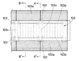
次に図18に示すように、左右のPCa柱204,204上に跨がって、PCaコンクリートからなる横梁部材(以下、PCa横梁という)206及びPCaコンクリートからなる板材(以下、ハーフPCaスラブという)207を設置すると共に、基礎梁201の両側の地盤上にそれぞれ構築した支保工208上に、PCaコンクリートからなる張り出し部材(以下、PCa張り出し部材という)209を設置し、PCa横梁206及びハーフPCaスラブ207上に鉄筋210を配筋する。そして次の図19に示すように、前記鉄筋210の配筋空間に後打ちコンクリート211を打設し、この後打ちコンクリート211とPCa柱204、PCa横梁206、ハーフPCaスラブ207及びPCa張り出し部材209を互いに一体化することによって、先に説明した図14,15に示す高架橋が構築される。なお図18及び図19において、それぞれ(A)は図13におけるA−A’位置に対応する部分での施工状況を示し、(B)は同B−B’位置に対応する部分での施工状況を示すものである。
【0006】
【発明が解決しようとする課題】
上記従来工法によれば、予め工場生産されたPCaコンクリート製品を使用することによって、現場打ちコンクリートのみで施工する場合のような型枠組立工事、配筋工事、コンクリート養生、型枠撤去作業等が削減又は不要となるので、工期を短縮することができる。しかし、この工法においては、PCa張り出し部材209は、後打ちコンクリート211によって一体化されるまで支保工208によって支持する必要があり、このため、支保工208の構築や解体・撤去作業が新たに必要となる。しかも、基礎梁101の施工後はこの支保工208の設置のために周囲の土の埋め戻し作業を早期に行わなければならない。
【0007】
本発明は、上記のような事情のもとになされたもので、その技術的課題とするところは、柱、梁、スラブにPCaコンクリート部材を用いて、両側に張り出し部を有する鉄筋コンクリート製の高架橋を構築する場合に、現場での型枠や支保工の施工をなくすことによって一層の省力化及び工期短縮を図ると共に、構築される高架橋の強度を向上することにある。
【0008】
【課題を解決するための手段】
上述した技術的課題は、本発明によって有効に解決することができる。
すなわち本発明に係るPCaコンクリート部材を用いた高架橋の施工法は、基礎梁上に所定間隔で並んだ左右2列のPCa柱を建て込み、次に左右に並んだ前記PCa柱の上端にPCa縦梁の両端を支持してこのPCa縦梁を架設し、左右両端がPCa柱上に支持されるPCa横梁の左右両側に前記PCa柱の上端位置と対応する空間を隔てて配置されると共に横梁主筋を介して前記PCa横梁に連結されたPCa張り出し梁を添え材に拘束してから、この添え材ごと前記PCa横梁とPCa張り出し梁の連結体を揚重して左右に並んだ前記PCa柱上に架設し、次に列方向に並んだ前記PCa横梁間にハーフPCaスラブを架設し、列方向に並んだ前記PCa張り出し梁間にPCa張り出しスラブを架設してから、前記PCa横梁とPCa張り出し梁の間の空間及び前記ハーフPCaスラブ上に後打ちコンクリートを打設する。
【0009】
PCa柱、PCa縦梁、PCa横梁、PCa張り出し梁、ハーフPCaスラブ及びPCa張り出しスラブは、工場生産されたプレキャスト製品であり、高強度・高品質のものを生産できる。このため、コンクリート成形後の乾燥・収縮がほぼ完了した状態で使用される。このため、現場打ちコンクリートで施工した場合のように、架橋構造体の表面にひび割れが発生するといったことがなく、耐久性の向上が図られると共に、精度良く施工できる。
【0010】
PCa横梁とPCa張り出し梁の連結体は、そのPCa張り出し梁を予め拘束した添え材と共にPCa柱の上に一度に架設される。前記連結体の架設後は、前記添え材が、前記PCa張り出し梁及びその上に架設されるPCa張り出しスラブの荷重を支保する。このため、地盤上への支保工の構築によって前記PCa張り出しスラブやPCa張り出し梁を支保する必要がない。また、PCa張り出しスラブは、列方向に並んだ各PCa張り出し梁の互いの対向面に形成された段差部上に掛合支持される構成とすることができる。
【0011】
PCa柱と、PCa横梁及びPCa張り出し梁と、ハーフPCaスラブと、PCa張り出しスラブは、後打ちコンクリートの打設によって互いに一体化され、これによって幅方向両側に張り出し部を有すると共に下面に縦梁及び横梁を有するスラブが形成される。この場合、例えばPCa柱の上端に突設された柱主筋の端部と、このPCa柱の上端に支持されたPCa縦梁の両端から突出された縦梁主筋の端部が、PCa横梁とPCa張り出し梁とを連結している横梁主筋と共に、前記PCa横梁とPCa張り出し梁の間の空間に充填された後打ちコンクリートに埋設された状態になり、更に前記空間内の後打ちコンクリートは、ハーフPCaスラブ上に打設された後打ちコンクリートと連続しているため、強固に接合一体化される。なお、施工完了後はPCa張り出し梁から添え材を取り外す。
【0012】
また、基礎梁上へのPCa柱の建て込みに際しては、基礎梁上面のPCa柱建て込み位置には予め柱連結筋が突設され、一方PCa柱内に埋設された柱主筋の下端がこのPCa柱の下端に形成された連結穴内に突設された構造とし、PCa柱の建て込みの際に前記連結穴内に挿入された前記柱連結筋が、前記連結穴内へ充填される無収縮モルタルを介して前記柱主筋の下端と連結されるモルタル充填継手構造とすることによって、作業が容易になると共に、所要の接合強度を得ることができる。
【0013】
【発明の実施の形態】
図3乃至図13は、本発明の一実施形態として、図1及び図2に示すようなビームスラブ型の高架橋を施工する方法を示すもので、図1は前記高架橋の概略構成を示す平面図、図2は図1におけるII−II線に沿って切断した断面図である。すなわちこの高架橋は、図1に示す状態を施工単位として施工されるもので、地盤G上の基礎梁1と、この基礎梁1上にその延長方向へ一定の間隔で並んで設けられた左右の柱2と、この柱2上に架設されスラブ本体部3a及びその左右両側に張り出し部3bを有するスラブ3とからなる。このスラブ3の下面には、前記左右の柱2の各列方向に延在された互いに平行な一対の縦梁3cと、両端が各柱2の上端位置で前記縦梁3c,3cに直交した横梁3dと、前記張り出し部3bを支持する張り出し梁3eが突出形成されている。
【0014】
この高架橋の施工においては、まず図3に示すように、従来と同様の方法によって、地盤Gに基礎梁1を施工し、PCa柱20をクレーン(図示省略)等によって搬入し、基礎梁1の左右所定位置に鉛直に建て込む。PCa柱20の内部には後述する柱主筋22や肋筋等の各種鉄筋が埋設されている。なお、この実施形態における高架橋は図3に示す断面と直交する方向へ延びるように施工されるものであり、前記PCa柱20は、架橋延長方向へ一定の間隔で左右2列に並んで建て込まれる。また、参照符号4は建て込んだPCa柱20を鉛直に支持するための仮設材である。
【0015】
図4は、基礎梁1とその上に建て込まれたPCa柱20との接合部の構造を示すもので、(A)は接合部の全体構造、(B)は(A)におけるB矢視部の拡大図である。すなわち、基礎梁1の上面におけるPCa柱20の建て込み位置にはこの基礎梁1に埋設された鉄筋の一部である所要数の柱連結筋11が突設されており、一方、PCa柱20の下端には前記各柱連結筋11と対応する位置に埋設されたスリーブ21によって所要数の連結穴21aが形成され、PCa柱20内に埋設された柱主筋22の下端部22aがこれら各連結穴21a内に突設され、柱主筋22の上端部22bがPCa柱20の上端から突出している。PCa柱20の建て込みに際しては、基礎梁1の上面の各柱連結筋11が前記各連結穴21a内に挿入され、その後、連結穴21a内へ無収縮モルタル23を充填することによって、この無収縮モルタル23を介して、連結穴21a内で柱主筋22の下端部22aと柱連結筋11が強固に連結される。
【0016】
次に図5に示すように、左右の列方向に並んだ各PCa柱20の上端にPCa縦梁33を架設する。このPCa縦梁33は、図5の断面と直交する方向(PCa柱20の列方向)に延在されるものであって、図6の斜視図に示すように、長手方向両端から縦梁主筋の端部33aが突出し、上面に肋筋33bが突出した構造を有する。
【0017】
また、左右に並んだPCa柱20,20上には、PCa縦梁33と直交する方向に、図7(A)(B)に示すようなPCa横梁31とPCa張り出し梁32,32との連結体30を架設する。PCa横梁31は左右(長手方向)両端が左右に並んだPCa柱20,20上に支持されるものであり、PCa張り出し梁32はこのPCa横梁31の左右両側に前記PCa柱20の上端位置と対応する空間Sを隔てて配置され基端が前記PCa柱20上に支持されるものである。図8の斜視図にも示すように、PCa横梁31は、長手方向両端から下部横梁主筋30aが突出し、上面から肋筋30bが突出した構造を有するものであって、前記下部横梁主筋30aの両端が左右のPCa張り出し梁32に埋設されると共に、前記肋筋30bの上端突出部を通して配設した上部横梁主筋30cの両端が左右のPCa張り出し梁32,32に埋設され、これによってPCa横梁31とPCa張り出し梁32,32が一体的に連結されているものである。
【0018】
PCa張り出し梁32には、後述するPCa張り出しスラブ35の両端を掛合支持するための段差部32aが形成されている。また、図7(B)に示すPCa横梁31及びPCa張り出し梁32は高架橋の施工単位における両端位置に設けられるもので、すなわち図7,図8(B)に示すPCa横梁31には、図7,図8(A)に示す一般形状のものと異なり、同図(B)に示すように、他の施工単位と連結するための凸段部31aが形成されている。
【0019】
PCa横梁31とPCa張り出し梁32,32の連結体30を架設するに際しては、予め前記PCa張り出し梁32,32を添え材としてのH型鋼5にワイヤ等により拘束する。すなわち図5に示す工程では、H型鋼5には左右のPCa張り出し梁32,32を拘束し、このH型鋼5を吊りビーム6の両端から下垂された一対の玉掛けワイヤ6aで玉掛けし、PCa横梁31を吊りビーム6の中間部から下垂された一対の玉掛けワイヤ6bで玉掛けし、吊りビーム6を介して吊り上げる。玉掛けワイヤ6a,6bの長さは、PCa横梁31と、H型鋼5に拘束されたPCa張り出し梁32が相対変位することなく図7に示す連結形状を保持しつつ吊り上げられるように規定されている。
【0020】
上述のようにして揚重したPCa横梁31とPCa張り出し梁32,32の連結体30は、空間SがそれぞれPCa柱20の上に一致するように位置決めして吊り下ろす。これによって、前記PCa横梁31の両端部及びPCa張り出し梁32の基端部は、それぞれ前記PCa柱20の上端に支持されると共に、前記PCa柱20の上端から突出した柱主筋22の上端部22b及びPCa縦梁33の縦梁主筋の端部33aが相対的に前記空間S内へ侵入し、前記空間S内の下部横梁主筋30a及び上部横梁主筋30cと交差する。前記連結体30をPCa柱20上に吊り下ろしたら、玉掛けワイヤ6a,6bによるH型鋼5及びPCa横梁31の玉掛け状態を解除し、クレーンによって吊りビーム6を回送して、次の連結体30の揚重・搬送を行う。
【0021】
PCa柱20上での連結体30の架設状態においては、PCa張り出し梁32,32がH型鋼5によって支保されているため、図18及び図19に示す従来技術のような支保工208の構築は不要である。また、支保工208の構築が不要となったことによって、基礎梁1の施工後の地盤Gの埋め戻し時期も特に規定する必要がなくなる。
【0022】
PCa縦梁33と、連結体30の架設作業が終わったら、図9及び図10に示すように、PCa柱20の列方向に並んだPCa横梁31,31間に板状のハーフPCaスラブ34をクレーンによって吊り上げ、架設する。このハーフPCaスラブ34の上面には、好ましくは、後述する後打ちコンクリート36との接合性を向上させるための、例えば粗面が形成され、あるいは所要数のジベル筋が設けられる。
【0023】
また、図11及び図12に示すように、PCa張り出しスラブ35をクレーンによって吊り上げ、PCa柱20の列方向に並んだPCa張り出し梁32,32間にこれを架設する。PCa張り出しスラブ35は図13の斜視図に示すような形状を呈するものであって、ハーフPCaスラブ34の上の後打ちコンクリート打設領域側に臨む端縁から多数の連結筋35aが突出しており、その架設に際しては、その長手方向両端部35bが、前記PCa張り出し梁32に形成された段差部32a上に掛合支持される。なお、ハーフPCaスラブ34上には、図10に示すように所要の鉄筋34aを配筋する。
【0024】
次に、各PCa柱20上の、PCa横梁31、PCa張り出し梁32及びPCa縦梁33の端部に囲まれた空間S及びハーフPCaスラブ34上に、図11に多数の点々を付して示す後打ちコンクリート36を打設する。このため、PCa柱20と、PCa横梁31及びPCa張り出し梁32と、PCa縦梁33と、ハーフPCaスラブ34と、PCa張り出しスラブ35は、打設された後打ちコンクリート36の経時的な硬化によって互いに一体接合される。このとき、PCa柱20の上端に突設された柱主筋の上端部22bと、このPCa縦梁33の両端から突出された縦梁主筋の端部33aが、横梁主筋30a,30cと共に、前記空間Sに充填された後打ちコンクリート36に埋設一体化され、ハーフPCaスラブ34上に打設された後打ちコンクリート36と連続しているため、強固に接合一体化される。
【0025】
上述した一連の工程によって構築された図1及び図2に示すビームスラブ型の高架橋は、スラブ3におけるスラブ本体部3aがハーフPCaスラブ34及びその上に打設された後打ちコンクリート36によって形成され、スラブ3における左右両側の張り出し部3b及び張り出し梁3eがそれぞれPCa張り出しスラブ35及びPCa張り出し梁32からなり、スラブ本体部3aの下面の縦梁3c及び横梁3dがそれぞれPCa縦梁33及びPCa横梁31からなり、前記後打ちコンクリート36を介して一体化されたものである。
【0026】
後打ちコンクリート36が硬化した後は、PCa張り出し梁32からH型鋼5を取り外すことによって、PCa張り出し梁32の支保状態を解除する。
【0027】
なお、上述の実施形態では、図5に示すPCa横梁31及びPCa張り出し梁32,32の架設に際して、PCa張り出し梁32,32をH型鋼5に拘束し、PCa横梁31はH型鋼5を介さずに玉掛けしているが、例えば前記PCa横梁31及びPCa張り出し梁32,32の双方をH型鋼5に拘束し、玉掛けはH型鋼5にのみ行うようにしても良い。また、後打ちコンクリート36はハーフPCaスラブ34上からPCa張り出しスラブ35上まで連続して打設するようにしても良い。
【0028】
【発明の効果】
本発明によると、次のような効果が実現される。
(1) コンクリート打設のための型枠やその支保工、作業足場等の組み立て・撤去が不要であるため、省力化されると共に連続的な施工が可能となり、工期が著しく短縮される。
(2) 基礎梁とPCa柱の柱主筋の接合をモルタル充填継手方式で行うため、柱の建て込み施工が容易で所要の耐力を得ることができる。
(3) スラブの張り出し部となるPCa張り出し梁を添え材に拘束するため、このPCa張り出し梁及びPCa張り出しスラブを支持する支保工の構築が不要であり、このため基礎梁施工後の基礎地盤の埋め戻し時期が制約を受けない。
【図面の簡単な説明】
【図1】本発明に係る施工法を実施することにより構築される高架橋の概略構成を示す平面図である。
【図2】図1におけるII−II線に沿って切断した断面図である。
【図3】上記高架橋を構築するための本発明の一実施形態において、基礎梁上に所定間隔で並んだ左右2列のPCa柱を建て込む工程を示す説明図である。
【図4】上記建て込み工程における基礎梁とPCa柱の連結構造を示すもので、(A)は概略構造説明図、(B)は(A)におけるB矢視部の拡大図である。
【図5】上記実施形態において、PCa柱上にPCa縦梁、PCa横梁及びPCa張り出し梁を架設する工程を示す説明図である。
【図6】上記PCa縦梁の斜視図である。
【図7】上記PCa横梁及びPCa張り出し梁の斜視図で、(A)は一般形状のもの、(B)は施工単位の両端に設けられるものを示す。
【図8】上記PCa横梁の斜視図である。
【図9】上記実施形態において、ハーフPCaスラブを架設する工程を示す説明図である。
【図10】図9におけるX−X’線に沿って切断した部分拡大断面図である。
【図11】上記実施形態において、PCa張り出しスラブを架設する工程を示す説明図である。
【図12】図11におけるXII−XII’線に沿って切断した部分拡大断面図である。
【図13】上記PCa張り出しスラブの斜視図である。
【図14】従来の施工法により構築される高架橋の概略構成を示す平面図である。
【図15】図14におけるA−A’線に沿って切断した断面図である。
【図16】従来の施工法において、基礎梁を施工する工程を示す説明図である。
【図17】従来の施工法において、基礎梁上に所定間隔で並んだ左右2列のPCa柱を建て込む工程を示す説明図である。
【図18】従来の施工法において、PCa横梁等の架設工程を示すもので、(A)は図14のA−A’位置に対応する部分での施工状況を示し、(B)は同B−B’位置に対応する部分での施工状況を示すものである。
【図19】従来の施工法において、後打ちコンクリートを打設する工程を示すもので、(A)は図14のA−A’位置に対応する部分での施工状況を示し、(B)は同B−B’位置に対応する部分での施工状況を示すものである。
【符号の説明】
1 基礎梁
5 H型鋼(添え材)
20 PCa柱(PCaコンクリート部材)
21a 連結穴
22 柱主筋
23 無収縮モルタル
30 PCa横梁とPCa張り出し梁の連結体
31 PCa横梁(PCaコンクリート部材)
32 PCa張り出し梁(PCaコンクリート部材)
32a 段差部
33 PCa縦梁(PCaコンクリート部材)
34 ハーフPCaスラブ(PCaコンクリート部材)
35 PCa張り出しスラブ(PCaコンクリート部材)
36 後打ちコンクリート[0001]
BACKGROUND OF THE INVENTION
The present invention relates to a technique for constructing a reinforced concrete viaduct using a precast (hereinafter abbreviated as PCa) concrete member for columns, beams, and slabs.
[0002]
[Prior art]
As shown in FIGS. 14 and 15, the beam slab type viaduct made of reinforced concrete has a
[0003]
FIGS. 16 to 19 show a typical conventional method of constructing a beam slab type viaduct having the above-described structure using a PCa concrete member. That is, in this conventional construction method, as shown in FIG. 16, first, reinforcing bar 201 (only a part of which is shown) is placed on ground G dug down to a required depth,
[0004]
Next, as shown in FIG. 17, a column member (hereinafter referred to as a PCa column) 204 made of PCa concrete is carried by a crane or the like, and is vertically built and joined to both sides in the width direction on the
[0005]
Next, as shown in FIG. 18, a cross beam member made of PCa concrete (hereinafter referred to as a PCa cross beam) 206 and a plate material made of PCa concrete (hereinafter referred to as a half PCa slab) straddling the left and
[0006]
[Problems to be solved by the invention]
According to the above-mentioned conventional construction method, by using PCa concrete products produced in the factory in advance, formwork assembling work, bar arrangement work, concrete curing, formwork removal work, etc., as in the case of construction using only cast-in-place concrete, etc. Since it is reduced or unnecessary, the construction period can be shortened. However, in this construction method, the PCa overhanging
[0007]
The present invention has been made under the circumstances as described above, and the technical problem is that a PCa concrete member is used for a column, a beam, and a slab, and a reinforced concrete viaduct having protruding portions on both sides is used. In constructing the construction, it is intended to further reduce the labor and shorten the construction period by eliminating the on-site formwork and support work, and to improve the strength of the constructed viaduct.
[0008]
[Means for Solving the Problems]
The technical problem described above can be effectively solved by the present invention.
That is, the construction method of the viaduct using the PCa concrete member according to the present invention is to lay two left and right PCa columns arranged at a predetermined interval on the foundation beam, and then to the upper end of the PCa columns arranged side by side. The PCa vertical beam is constructed by supporting both ends of the beam, and the left and right ends are arranged on the left and right sides of the PCa horizontal beam supported on the PCa column with a space corresponding to the upper end position of the PCa column, and the horizontal beam main bar The PCa overhanging beam connected to the PCa horizontal beam is constrained to an attachment material, and the connection body of the PCa horizontal beam and the PCa overhanging beam is lifted together with the attachment material on the PCa column arranged side by side. erection, and then bridged half PCa slab to the PCa transverse Harima aligned in the column direction, after erection of PCa overhanging slab to the PCa overhang Harima aligned in the column direction, the PCa cross beam and PCa Ri out to pouring the post-deposited concrete space and the half PCa on slab between the beams.
[0009]
PCa pillars, PCa vertical beams, PCa horizontal beams, PCa overhanging beams, half PCa slabs and PCa overhanging slabs are factory-produced precast products that can be produced with high strength and high quality. For this reason, it is used in a state in which drying and shrinkage after concrete molding are almost completed. For this reason, there is no occurrence of cracks on the surface of the bridge structure as in the case of construction with cast-in-place concrete, and durability can be improved and construction can be performed with high accuracy.
[0010]
The connecting body of the PCa lateral beam and the PCa projecting beam is constructed at once on the PCa column together with an accessory that restrains the PCa projecting beam in advance. After the connection body is installed, the accessory supports the load of the PCa projecting beam and the PCa projecting slab installed on the PCa projecting beam. For this reason, it is not necessary to support the PCa projecting slab or the PCa projecting beam by constructing a supporting work on the ground. Further, the PCa projecting slab can be configured to be hooked and supported on stepped portions formed on the mutually facing surfaces of the PCa projecting beams arranged in the column direction.
[0011]
The PCa column, the PCa transverse beam and the PCa overhanging beam, the half PCa slab, and the PCa overhanging slab are integrated with each other by placement of post-cast concrete, thereby having a protruding portion on both sides in the width direction and a vertical beam and A slab having a cross beam is formed. In this case, for example, the end of the column main bar protruding from the upper end of the PCa column and the end of the vertical beam main bar protruding from both ends of the PCa vertical beam supported by the upper end of the PCa column are the PCa horizontal beam and PCa. Along with the cross beam main bar connecting the overhanging beam, the space is placed in the post-cast concrete filled in the space between the PCa horizontal beam and the PCa overhang beam, and the post-cast concrete in the space is half PCa. Because it is continuous with post-cast concrete placed on the slab, it is firmly joined and integrated. After the construction is completed, the attachment material is removed from the PCa projecting beam.
[0012]
In addition, when the PCa column is built on the foundation beam, a column connecting bar protrudes in advance at the PCa column building position on the upper surface of the foundation beam, while the lower end of the column main bar embedded in the PCa column is the PCa. It has a structure projecting in a connecting hole formed at the lower end of the column, and the column connecting bar inserted into the connecting hole when the PCa column is installed is inserted through a non-shrink mortar filled in the connecting hole. By using a mortar-filled joint structure connected to the lower end of the column main bar, the work becomes easy and the required joint strength can be obtained.
[0013]
DETAILED DESCRIPTION OF THE INVENTION
FIGS. 3 to 13 show a method for constructing a beam slab type viaduct as shown in FIGS. 1 and 2 as an embodiment of the present invention. FIG. 1 is a plan view showing a schematic configuration of the viaduct. 2 is a cross-sectional view taken along line II-II in FIG. That is, this viaduct is constructed with the state shown in FIG. 1 as a construction unit, and the left and right foundation beams 1 on the ground G and the left and right sides provided on the
[0014]
In the construction of this viaduct, first, as shown in FIG. 3, the
[0015]
FIG. 4 shows the structure of the joint portion between the
[0016]
Next, as shown in FIG. 5, a PCa
[0017]
Further, on the
[0018]
The
[0019]
When the connecting
[0020]
The connecting
[0021]
Since the
[0022]
When the installation work of the PCa
[0023]
Further, as shown in FIGS. 11 and 12, the
[0024]
Next, a large number of dots are added to FIG. 11 on the space S and the
[0025]
The beam slab type viaduct shown in FIG. 1 and FIG. 2 constructed by the series of steps described above is formed by a
[0026]
After the post-cast concrete 36 is hardened, the supporting state of the
[0027]
In the above-described embodiment, when the
[0028]
【The invention's effect】
According to the present invention, the following effects are realized.
(1) Since there is no need to assemble / remove the formwork for concrete placement, its supporting work, work scaffolding, etc., labor saving and continuous construction are possible, and the construction period is remarkably shortened.
(2) Since the foundation beam and the main column reinforcement of the PCa column are joined by the mortar filling joint method, the column can be easily built and the required strength can be obtained.
(3) Since the PCa overhanging beam, which is the slab overhanging part, is constrained to the support material, it is not necessary to construct a support to support the PCa overhanging beam and the PCa overhanging slab. The backfill time is not restricted.
[Brief description of the drawings]
FIG. 1 is a plan view showing a schematic configuration of a viaduct constructed by carrying out a construction method according to the present invention.
2 is a cross-sectional view taken along line II-II in FIG.
FIG. 3 is an explanatory diagram showing a process of building two columns of left and right PCa columns arranged at predetermined intervals on a foundation beam in an embodiment of the present invention for constructing the viaduct.
FIGS. 4A and 4B show a connection structure of a foundation beam and a PCa column in the erection process, where FIG. 4A is a schematic structural explanatory view, and FIG.
FIG. 5 is an explanatory diagram illustrating a process of laying a PCa vertical beam, a PCa horizontal beam, and a PCa projecting beam on a PCa column in the embodiment.
FIG. 6 is a perspective view of the PCa vertical beam.
FIGS. 7A and 7B are perspective views of the PCa horizontal beam and the PCa projecting beam, where FIG. 7A shows a general shape, and FIG. 7B shows what is provided at both ends of a construction unit.
FIG. 8 is a perspective view of the PCa transverse beam.
FIG. 9 is an explanatory diagram showing a process of laying a half PCa slab in the embodiment.
10 is a partially enlarged cross-sectional view taken along the line XX ′ in FIG. 9;
FIG. 11 is an explanatory diagram showing a process of laying a PCa projecting slab in the embodiment.
12 is a partial enlarged cross-sectional view taken along line XII-XII ′ in FIG.
FIG. 13 is a perspective view of the PCa projecting slab.
FIG. 14 is a plan view showing a schematic configuration of a viaduct constructed by a conventional construction method.
15 is a cross-sectional view taken along line AA ′ in FIG.
FIG. 16 is an explanatory diagram showing a process of constructing a foundation beam in a conventional construction method.
FIG. 17 is an explanatory diagram showing a process of building two right and left PCa columns arranged at a predetermined interval on a foundation beam in a conventional construction method.
18A and 18B show a construction process of a PCa cross beam and the like in the conventional construction method, where FIG. 18A shows a construction situation at a portion corresponding to the position AA ′ in FIG. 14 and FIG. -The construction status at the part corresponding to the position B 'is shown.
FIG. 19 shows a process for placing post-cast concrete in a conventional construction method, where (A) shows the construction status at a portion corresponding to the position AA ′ in FIG. 14, and (B) shows The construction status at the portion corresponding to the BB ′ position is shown.
[Explanation of symbols]
1 Foundation beam 5 H-shaped steel (attachment)
20 PCa pillar (PCa concrete member)
32 PCa overhang beam (PCa concrete member)
34 Half PCa slab (PCa concrete member)
35 PCa overhang slab (PCa concrete member)
36 Post-cast concrete
Claims (4)
左右に並んだ前記PCa柱の上端にPCa縦梁の両端を支持してこのPCa縦梁を架設する工程と、
左右両端がPCa柱上に支持されるPCa横梁の左右両側に前記PCa柱の上端位置と対応する空間を隔てて配置されると共に横梁主筋を介して前記PCa横梁に連結されたPCa張り出し梁を添え材に拘束してから、この添え材ごと前記PCa横梁とPCa張り出し梁の連結体を揚重して左右に並んだ前記PCa柱上に架設する工程と、
列方向に並んだ前記PCa横梁間にハーフPCaスラブを架設し、列方向に並んだ前記PCa張り出し梁間にPCa張り出しスラブを架設する工程と、
前記PCa横梁とPCa張り出し梁の間の空間及び前記ハーフPCaスラブ上に後打ちコンクリートを打設する工程と、
からなることを特徴とするPCaコンクリート部材を用いた高架橋の施工法。Building two columns of left and right PCa columns arranged at predetermined intervals on the foundation beam;
Supporting the both ends of the PCa vertical beam at the upper ends of the PCa columns arranged side by side, and laying the PCa vertical beam;
The left and right ends of the PCa horizontal beam supported on the PCa column are arranged on both left and right sides with a space corresponding to the upper end position of the PCa column, and a PCa projecting beam connected to the PCa horizontal beam via a horizontal beam main bar is attached. After constraining to the material, lifting the connected body of the PCa transverse beam and the PCa projecting beam together with the attachment material and laying it on the PCa pillars arranged side by side;
Laying a half PCa slab between the PCa lateral beams arranged in a row direction, and constructing a PCa projecting slab between the PCa projecting beams arranged in a row direction ;
Placing post-cast concrete on the space between the PCa transverse beam and the PCa projecting beam and on the half PCa slab;
Construction method of viaduct using PCa concrete member characterized by comprising.
PCa縦梁の架設及びPCa横梁とPCa張り出し梁の連結体の架設の際に、
前記PCa横梁とPCa張り出し梁との間の空間に、PCa柱の上端から突出した柱主筋の端部と、PCa縦梁の両端から突出した縦梁主筋の端部が挿入されることを特徴とするPCaコンクリート部材を用いた高架橋の施工法。In the description of claim 1,
When installing the PCa vertical beam and connecting the PCa horizontal beam and PCa extension beam ,
Ends of column main bars protruding from the upper end of the PCa column and ends of vertical beam main bars protruding from both ends of the PCa vertical beam are inserted into the space between the PCa horizontal beam and the PCa projecting beam. Construction method of viaduct using PCa concrete member.
列方向に並んだ各PCa張り出し梁の互いの対向面にはPCa張り出しスラブを掛合支持する段差部が形成されていることを特徴とするPCaコンクリート部材を用いた高架橋の施工法。In the description of claim 1 or 2,
A method of constructing a viaduct using a PCa concrete member, wherein stepped portions for hooking and supporting a PCa overhanging slab are formed on the mutually facing surfaces of the PCa overhanging beams arranged in a row direction.
基礎梁上面のPCa柱建て込み位置には予め柱連結筋が突設されており、
PCa柱内に埋設された柱主筋の下端がこのPCa柱の下端に形成された連結穴内に突設されており、
PCa柱の建て込みの際に前記連結穴内に挿入された前記柱連結筋が、前記連結穴内へ充填される無収縮モルタルを介して前記柱主筋の下端と連結されることを特徴とするPCaコンクリート部材を用いた高架橋の施工法。In any one of Claims 1 thru | or 3,
Column connecting bars project in advance at the PCa column building position on the upper surface of the foundation beam.
The lower end of the column main reinforcement embedded in the PCa column protrudes into a connecting hole formed in the lower end of the PCa column,
The PCa concrete, wherein the column connecting bars inserted into the connecting holes when the PCa columns are built are connected to the lower ends of the column main bars through non-shrink mortar filled in the connecting holes. Construction method of viaduct using members.
Priority Applications (1)
| Application Number | Priority Date | Filing Date | Title |
|---|---|---|---|
| JP25089296A JP3841493B2 (en) | 1996-09-03 | 1996-09-03 | Construction method of viaduct using PCa concrete member |
Applications Claiming Priority (1)
| Application Number | Priority Date | Filing Date | Title |
|---|---|---|---|
| JP25089296A JP3841493B2 (en) | 1996-09-03 | 1996-09-03 | Construction method of viaduct using PCa concrete member |
Publications (2)
| Publication Number | Publication Date |
|---|---|
| JPH1077607A JPH1077607A (en) | 1998-03-24 |
| JP3841493B2 true JP3841493B2 (en) | 2006-11-01 |
Family
ID=17214583
Family Applications (1)
| Application Number | Title | Priority Date | Filing Date |
|---|---|---|---|
| JP25089296A Expired - Fee Related JP3841493B2 (en) | 1996-09-03 | 1996-09-03 | Construction method of viaduct using PCa concrete member |
Country Status (1)
| Country | Link |
|---|---|
| JP (1) | JP3841493B2 (en) |
Cited By (1)
| Publication number | Priority date | Publication date | Assignee | Title |
|---|---|---|---|---|
| CN110644371A (en) * | 2019-09-30 | 2020-01-03 | 中铁大桥局集团第五工程有限公司 | Prefabricated capping beam installation method and system |
Families Citing this family (6)
| Publication number | Priority date | Publication date | Assignee | Title |
|---|---|---|---|---|
| JP3940587B2 (en) * | 2001-11-13 | 2007-07-04 | 大成建設株式会社 | Construction method of divided bridge type traffic route |
| JP3862707B2 (en) * | 2004-03-19 | 2006-12-27 | 日本カイザー株式会社 | Construction method of overpass slab and precast concrete plate for overhang slab |
| JP4680803B2 (en) * | 2006-03-07 | 2011-05-11 | 戸田建設株式会社 | Construction method of three-dimensional viaduct structure |
| JP5713747B2 (en) * | 2010-03-24 | 2015-05-07 | 戸田建設株式会社 | Three-dimensional viaduct structure and its construction method |
| JP6276613B2 (en) * | 2014-03-10 | 2018-02-07 | 三井住友建設株式会社 | Precast wall railing joint structure |
| CN106087762B (en) * | 2016-08-09 | 2018-01-16 | 杭州江润科技有限公司 | Pier stud synchronously pours the construction method of formwork erecting structure with straining beam |
-
1996
- 1996-09-03 JP JP25089296A patent/JP3841493B2/en not_active Expired - Fee Related
Cited By (1)
| Publication number | Priority date | Publication date | Assignee | Title |
|---|---|---|---|---|
| CN110644371A (en) * | 2019-09-30 | 2020-01-03 | 中铁大桥局集团第五工程有限公司 | Prefabricated capping beam installation method and system |
Also Published As
| Publication number | Publication date |
|---|---|
| JPH1077607A (en) | 1998-03-24 |
Similar Documents
| Publication | Publication Date | Title |
|---|---|---|
| JP3818020B2 (en) | Cross-section precast segment method | |
| JP7134070B2 (en) | Construction method of top slab of underground structure | |
| KR100923564B1 (en) | Precast concrete panel, construction method and structure of precast concrete panel using steel plate | |
| JP3841493B2 (en) | Construction method of viaduct using PCa concrete member | |
| KR200407092Y1 (en) | Support Structure for PC Panel of Cantilever Part | |
| JP2535722B2 (en) | Reinforcement concrete column and steel beam connection structure and building construction method | |
| JP2000273939A (en) | Culvert construction method | |
| KR101482523B1 (en) | Nodular Box Girder, and Nodular Box Girder Bridge and Constructing Method thereof | |
| JP3701078B2 (en) | Road slab construction method | |
| JP3945668B2 (en) | Construction method of concrete pier | |
| JP3824242B2 (en) | Viaduct-free support construction method | |
| JPH0657710A (en) | Construction of concrete main tower | |
| JPH1136229A (en) | Construction method for reinforced concrete bridge pier | |
| JPH1096210A (en) | Method of executing enlargement of bridge pier | |
| JP2000129633A (en) | Erection method for bridge floor slab | |
| KR101531839B1 (en) | Arch-Rahmen type tunnel construction method | |
| JP2864906B2 (en) | Precast wall joining method | |
| JP7257868B2 (en) | Precast concrete member, foundation structure and construction method for foundation structure | |
| JP2674470B2 (en) | Floor frame structure by combining precast members | |
| JPH05239810A (en) | Constructing method for reinforced concrete arch bridge | |
| JP6555623B2 (en) | Concrete structure and construction method thereof | |
| JPH10299003A (en) | Foundation work using precast concrete member | |
| JP3690463B2 (en) | Construction method of viaduct | |
| JPH10102423A (en) | Pca form and construction method of pier using the same pca form | |
| JP2972955B2 (en) | Column and beam joining method and its structure |
Legal Events
| Date | Code | Title | Description |
|---|---|---|---|
| A977 | Report on retrieval |
Free format text: JAPANESE INTERMEDIATE CODE: A971007 Effective date: 20060223 |
|
| A131 | Notification of reasons for refusal |
Free format text: JAPANESE INTERMEDIATE CODE: A131 Effective date: 20060322 |
|
| A521 | Request for written amendment filed |
Free format text: JAPANESE INTERMEDIATE CODE: A523 Effective date: 20060516 |
|
| TRDD | Decision of grant or rejection written | ||
| A01 | Written decision to grant a patent or to grant a registration (utility model) |
Free format text: JAPANESE INTERMEDIATE CODE: A01 Effective date: 20060712 |
|
| A61 | First payment of annual fees (during grant procedure) |
Free format text: JAPANESE INTERMEDIATE CODE: A61 Effective date: 20060808 |
|
| R150 | Certificate of patent or registration of utility model |
Free format text: JAPANESE INTERMEDIATE CODE: R150 |
|
| FPAY | Renewal fee payment (event date is renewal date of database) |
Free format text: PAYMENT UNTIL: 20090818 Year of fee payment: 3 |
|
| FPAY | Renewal fee payment (event date is renewal date of database) |
Free format text: PAYMENT UNTIL: 20100818 Year of fee payment: 4 |
|
| FPAY | Renewal fee payment (event date is renewal date of database) |
Free format text: PAYMENT UNTIL: 20110818 Year of fee payment: 5 |
|
| FPAY | Renewal fee payment (event date is renewal date of database) |
Free format text: PAYMENT UNTIL: 20110818 Year of fee payment: 5 |
|
| FPAY | Renewal fee payment (event date is renewal date of database) |
Free format text: PAYMENT UNTIL: 20120818 Year of fee payment: 6 |
|
| FPAY | Renewal fee payment (event date is renewal date of database) |
Free format text: PAYMENT UNTIL: 20120818 Year of fee payment: 6 |
|
| FPAY | Renewal fee payment (event date is renewal date of database) |
Free format text: PAYMENT UNTIL: 20130818 Year of fee payment: 7 |
|
| LAPS | Cancellation because of no payment of annual fees |