JP3841237B2 - Robot and load supporting method thereof - Google Patents
Robot and load supporting method thereof Download PDFInfo
- Publication number
- JP3841237B2 JP3841237B2 JP13731097A JP13731097A JP3841237B2 JP 3841237 B2 JP3841237 B2 JP 3841237B2 JP 13731097 A JP13731097 A JP 13731097A JP 13731097 A JP13731097 A JP 13731097A JP 3841237 B2 JP3841237 B2 JP 3841237B2
- Authority
- JP
- Japan
- Prior art keywords
- robot arm
- stopper
- actuator
- robot
- contact
- Prior art date
- Legal status (The legal status is an assumption and is not a legal conclusion. Google has not performed a legal analysis and makes no representation as to the accuracy of the status listed.)
- Expired - Fee Related
Links
Images

Landscapes
- Manipulator (AREA)
Description
【0001】
【発明の属する技術分野】
本発明は、マニピュレータ等の関節駆動に適用して、その可動範囲を機械的に制限するロボットの動作制限装置及び方法に関する。
【0002】
【従来の技術】
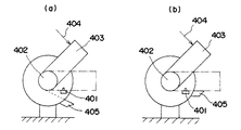
従来、アクチュエータの可動範囲限界での可動範囲の制限は、図4に示すようになっている。図において、401はリミットスイッチ、402は回転軸、403はロボットアーム、404は負荷、405はロボットアームのストッパである。
通常、リミットスイッチ401及びストッパ405の配置は、図4(a)に示すようになり、回転軸402に固定されたロボットアーム403が可動範囲限界に達した時リミットスイッチ401が作動する。リミットスイッチ401の作動信号は上位制御装置に送られ、リミットスイッチ401を越えてロボットアーム403が動作しないように速度指令の場合には指令を0に、位置指令の場合には指令を固定する。ストッパ405は、安全対策等のために設けられたものであり、何らかの原因でリミットスイッチ401が作動しなかった場合、または、負荷404が回転軸402においてアクチュエータの持つ最大定格トルクを越える負荷であった場合に対応して最終的にロボットアーム403を停止させるものである。
また、図4(b)に示すようなリミットスイッチ401及びストッパ405の配置も考えられる。
【0003】
【発明が解決しようとする課題】
ところが、従来技術では、リミットスイッチ及びストッパの配置が図4(a)に示すような場合、ロボットアームが可動範囲限界を越えて動作しないようにするため、アクチュエータへの指令を供給し続けなければならないという問題があった。また、何らかの原因でリミットスイッチが作動しなかった場合、または、指令を供給し続けていてもロボットアームに過負荷が発生した場合、ロボットアームが可動範囲限界を越えて動作してしまうという問題があった。
また、リミットスイッチ及びストッパの配置が図4(b)に示すような場合、ロボットアームがストッパに接触した時にリミットスイッチが作動できるようにするため、リミットスイッチの取り付け位置を調整しなければならず、その調整作業に手間と時間がかかるという問題があった。
そこで、本発明は、可動範囲限界にロボットアームが達してもアクチュエータへの指令を供給し続けるということがなく、また、アクチュエータの持つ最大定格トルクを越えた負荷にも対応できるようにし、さらに、ストッパの取り付け位置を微調整することのないロボットの動作制限装置及び方法を提供することを目的とする。
【0004】
【課題を解決するための手段】
上記問題を解決するため、本発明のロボットの動作制限装置は、ロボットアームの運動を制限するための機械的なストッパを持つロボットの動作制限装置において、前記ストッパに前記ロボットアームが接触したときに感応する感圧センサを設け、かつ前記感圧センサが前記ロボットアームの接触を感知したときにロボットアームのアクチュエータに供給するトルク指令を切断する手段を備えたものである。
また、本発明のロボットの動作制限方法は、ロボットアームの運動を制限するための機械的なストッパを持ち、前記ストッパに接触力を検出する機能を備えたロボットの動作制限方法において、前記ロボットアームが前記ストッパに接触した時、接触力を検出し、その接触力に応じて前記ロボットアームのアクチュエータに供給するトルク指令を切断するようにしたものである。
上記手段により、可動範囲限界にロボットアームが達した場合、感圧センサが接触を検出するので、感圧センサの設置位置の微調整などは不要であり、また接触を検出した時点でトルク指令を切断でき、無駄な指令を供給する必要がない。
さらに、ストッパによりロボットアームの運動を制限することができるので、アクチュエータの持つ最大定格トルクを越える負荷でも支持できる。
【0005】
【発明の実施の形態】
以下、本発明の実施の形態を図に基づいて説明する。
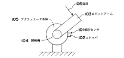
図1は本発明の実施例に係るストッパ付きアクチュエータの構造説明図である。図に示すように、本実施例は、アクチュエータ本体105と、ストッパ102と、ストッパ102に固定された感圧センサ101と、回転軸104と、回転軸104に固定されたロボットアーム103とを備えている。感圧センサ101は、例えば感圧導電ゴム等の周知のセンサを用いることができる。
図1において、アクチュエータにトルク指令が供給されると回転軸104が回転し、ロボットアーム103が運動する。ロボットアーム103の可動範囲限界にロボットアーム103が達すると感圧センサ101に接触する。感圧センサ101はその接触情報を出力することができる。従って、本実施例では、ロボットアーム103が可動範囲限界に達した場合、ロボットアーム103と感圧センサ101との接触情報を出力することができる。また、ストッパ102によりロボットアーム103は、負荷106が回転軸104においてアクチュエータの最大定格トルクを越える負荷であっても可動範囲を越えずに運動を停止することができる。
【0006】
【課題を解決するための手段】
上記課題を解決するため、本発明は、次のように構成したのである。
請求項1に記載の発明は、ロボットアームの運動を制限するための機械的なストッパと、前記ストッパの前記ロボットアーム接触部に固定されて前記ロボットアームが接触したときに感応する感圧センサと、前記ロボットアームのアクチュエータに供給するトルク指令を切断するトルク指令切断手段と、を備えたロボットにおいて、前記感圧センサが前記ロボットアームの接触を感知したとき、前記トルク指令切断手段が、前記トルク指令を切断するとともに、前記ストッパが前記ロボットアームに作用する負荷を支持することを特徴とするものである。
また、請求項2に記載の発明は、ロボットアームの運動を制限するための機械的なストッパと、前記ストッパに固定されて前記ロボットアームが接触したときに感応する感圧センサと、を備えたロボットにおいて、前記感圧センサが前記ロボットアームの接触を感知したとき、前記ロボットアームのアクチュエータに供給するトルク指令を切断し、前記ストッパが前記ロボットアームに作用する負荷を支持することを特徴とするものである。
【0007】
図3は本発明の実施例に係るストッパ付きアクチュエータを用いた適用例の構成図である。本実施例は、マニピュレータベース303と第1のアクチュエータ304と第2のアクチュエータ305と第3のアクチュエータ306とから構成されるマニピュレータ部301と、第3のアクチュエータに接続されたストッパ付きのアクチュエータ本体105で構成されるハンド部302とで構成される。ハンド部302のアクチュエータ本体105は、ストッパ102と、ストッパ102に固定された感圧センサ101と、回転軸104と、回転軸104に固定されたロボットアーム103とを備えている。図では支持物体312をハンド部302で、すなわち、アクチュエータ本体105のロボットアーム103で支持している。一般にハンド部302で使用されるアクチュエータの定格最大トルクは、マニピュレータ部301で使用されるアクチュエータの定格最大トルクよりも小さい。従ってロボットアーム103で支持できる物体の重量はハンド部302で構成されるアクチュエータの最大定格トルクで決定される。ところが、本実施例では、ハンド部302にストッパ付きのアクチュエータ本体105を使用しているため、支持物体312の重量が回転軸104においてアクチュエータ本体105の持つ最大定格トルクを越える負荷であっても、ストッパ102によりロボットアーム103が支持物体312を支持する。更に、この時、感圧センサ101により圧力情報が検出されるので、アクチュエータ本体105にトルク指令を供給する必要がなく効率的である。なお、マニピュレータ部301のアクチュエータも必要に応じてストッパ付きのアクチュエータを使用してもよい。
上述した実施例では、アクチュエータとして回転軸を備えたものを使用していたが、本発明はこれに限るものではなく、直動軸を備えたアクチュエータを使用してもよい。
【0008】
【発明の効果】
以上述べたように、本発明によれば、可動範囲を制限することのできるストッパと、ロボットアームとストッパとの接触を検出する機能と、感圧センサが前記ロボットアームの接触を感知したときにロボットアームのアクチュエータに供給するトルク指令を切断する手段を備えたため、感圧センサをストッパに装着するだけで位置決めや微調整の問題がなく、またストッパとの接触を検出した時点で指令を切断でき、無駄な指令を供給することがないという効果がある。
さらに、機械的なストッパによりロボットアームを支持するため、アクチュエータの持つ最大定格トルクを越えた負荷でも支持できるという効果がある。
【図面の簡単な説明】
【図1】 本発明の実施例に係るストッパ付きアクチュエータの構造説明図である。
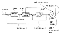
【図2】 本発明の実施例に係るストッパ付きアクチュエータのブロック図である。
【図3】 本発明の実施例に係るストッパ付きアクチュエータを用いた適用例の構成図である。
【図4】 従来のアクチュエータの可動範囲限界での可動範囲制限を示す概念図である。
【符号の説明】
101 感圧センサ、102 ストッパ、103 ロボットアーム、104 回転軸、105 アクチュエータ本体、106 負荷、204 トルク指令制御部、205 速度指令アンプ、206 トルク指令アンプ、301 マニピュレータ部、302 ハンド部、303 マニピュレータベース、304 第1のアクチュエータ、305 第2のアクチュエータ、306 第3のアクチュエータ、312 支持物体、401 リミットスイッチ、402 回転軸、403 ロボットアーム、404 負荷、405 ストッパ[0001]
BACKGROUND OF THE INVENTION
The present invention relates to an apparatus and method for restricting the operation of a robot that is applied to joint driving of a manipulator or the like and mechanically limits the movable range thereof.
[0002]
[Prior art]
Conventionally, the limitation of the movable range at the movable range limit of the actuator is as shown in FIG. In the figure, 401 is a limit switch, 402 is a rotating shaft, 403 is a robot arm, 404 is a load, and 405 is a stopper of the robot arm.
Normally, the arrangement of the
An arrangement of the
[0003]
[Problems to be solved by the invention]
However, in the prior art, when the arrangement of the limit switch and the stopper is as shown in FIG. 4 (a), in order to prevent the robot arm from moving beyond the movable range limit, it is necessary to continue to supply commands to the actuator. There was a problem of not becoming. In addition, if the limit switch does not operate for some reason, or if the robot arm is overloaded even if the command continues to be supplied, the robot arm will move beyond the movable range limit. there were.
If the limit switch and stopper are arranged as shown in Fig. 4 (b), the limit switch mounting position must be adjusted to enable the limit switch to operate when the robot arm contacts the stopper. There is a problem that the adjustment work takes time and effort.
Therefore, the present invention does not continue to supply a command to the actuator even when the robot arm reaches the limit of the movable range, and can cope with a load exceeding the maximum rated torque of the actuator, An object of the present invention is to provide an apparatus and a method for restricting the operation of a robot without finely adjusting the mounting position of the stopper.
[0004]
[Means for Solving the Problems]
In order to solve the above problems, the robot motion limiting device of the present invention is a robot motion limiting device having a mechanical stopper for limiting the motion of the robot arm, when the robot arm comes into contact with the stopper. A sensitive pressure sensor is provided, and means for cutting a torque command supplied to the actuator of the robot arm when the pressure sensor senses contact of the robot arm is provided.
The robot motion limiting method of the present invention is a robot motion limiting method having a mechanical stopper for limiting the motion of the robot arm and having a function of detecting contact force on the stopper. When a contact with the stopper is detected, a contact force is detected, and a torque command supplied to the actuator of the robot arm is cut according to the contact force.
When the robot arm reaches the limit of the movable range by the above means, the pressure sensor detects contact, so fine adjustment of the installation position of the pressure sensor is unnecessary, and when the contact is detected, a torque command is issued. It can be cut and there is no need to supply useless commands.
Furthermore, since the movement of the robot arm can be limited by the stopper, it can be supported even with a load exceeding the maximum rated torque of the actuator.
[0005]
DETAILED DESCRIPTION OF THE INVENTION
Hereinafter, embodiments of the present invention will be described with reference to the drawings.
FIG. 1 is an explanatory view of the structure of an actuator with a stopper according to an embodiment of the present invention. As shown in the figure, this embodiment includes an
In FIG. 1, when a torque command is supplied to the actuator, the
[0006]
[Means for Solving the Problems]
In order to solve the above problems, the present invention is configured as follows.
The invention according to claim 1 is a mechanical stopper for restricting the movement of the robot arm, and a pressure sensor that is fixed to the robot arm contact portion of the stopper and senses when the robot arm comes into contact. A torque command cutting means for cutting a torque command supplied to the actuator of the robot arm, and when the pressure sensor senses contact of the robot arm, the torque command cutting means In addition to cutting the command, the stopper supports a load acting on the robot arm.
The invention according to claim 2 includes a mechanical stopper for restricting the movement of the robot arm, and a pressure sensor that is fixed to the stopper and is sensitive when the robot arm comes into contact. In the robot, when the pressure sensor senses contact of the robot arm, the torque command supplied to the actuator of the robot arm is cut off, and the stopper supports a load acting on the robot arm. Is.
[0007]
FIG. 3 is a configuration diagram of an application example using an actuator with a stopper according to an embodiment of the present invention. In this embodiment, a manipulator unit 301 including a
In the above-described embodiments, the actuator provided with the rotating shaft is used, but the present invention is not limited to this, and an actuator provided with a linear motion shaft may be used.
[0008]
【The invention's effect】
As described above, according to the present invention, the stopper capable of limiting the movable range, the function of detecting the contact between the robot arm and the stopper, and the pressure sensor detects the contact of the robot arm. Since there is a means to cut the torque command supplied to the actuator of the robot arm, there is no problem of positioning or fine adjustment just by attaching the pressure sensor to the stopper, and the command can be cut when contact with the stopper is detected. There is an effect that a useless command is not supplied.
Furthermore, since the robot arm is supported by a mechanical stopper, there is an effect that it can be supported even with a load exceeding the maximum rated torque of the actuator.
[Brief description of the drawings]
FIG. 1 is an explanatory diagram of a structure of an actuator with a stopper according to an embodiment of the present invention.
FIG. 2 is a block diagram of an actuator with a stopper according to an embodiment of the present invention.
FIG. 3 is a configuration diagram of an application example using an actuator with a stopper according to an embodiment of the present invention.
FIG. 4 is a conceptual diagram showing a movable range restriction at a movable range limit of a conventional actuator.
[Explanation of symbols]
DESCRIPTION OF
Claims (2)
前記ロボットアームのアクチュエータに供給するトルク指令を切断するトルク指令切断手段と、を備えたロボットにおいて、
前記感圧センサが前記ロボットアームの接触を感知したとき、
前記トルク指令切断手段が、前記トルク指令を切断するとともに、前記ストッパが前記ロボットアームに作用する負荷を支持することを特徴とするロボット。A mechanical stopper for limiting the movement of the robot arm, and a pressure-sensitive sensor that is fixed to the robot arm contact portion of the stopper and senses when the robot arm comes into contact ;
A robot equipped with a torque command cutting means for cutting the torque command supplied to the actuator of the robot arm,
When the pressure sensor senses contact of the robot arm,
Robot said torque command cutting means, with cutting the torque command, the stopper is characterized in that for supporting the load acting on the robot arm.
前記感圧センサが前記ロボットアームの接触を感知したとき、
前記ロボットアームのアクチュエータに供給するトルク指令を切断し、
前記ストッパが前記ロボットアームに作用する負荷を支持することを特徴とするロボットの負荷支持方法。In a robot provided with a mechanical stopper for limiting the movement of the robot arm, and a pressure sensor that is fixed to the stopper and is sensitive when the robot arm comes into contact ,
When the pressure sensor senses contact of the robot arm ,
Cutting the torque command supplied to the actuator of the robot arm ;
A load supporting method for a robot, wherein the stopper supports a load acting on the robot arm .
Priority Applications (1)
| Application Number | Priority Date | Filing Date | Title |
|---|---|---|---|
| JP13731097A JP3841237B2 (en) | 1997-05-27 | 1997-05-27 | Robot and load supporting method thereof |
Applications Claiming Priority (1)
| Application Number | Priority Date | Filing Date | Title |
|---|---|---|---|
| JP13731097A JP3841237B2 (en) | 1997-05-27 | 1997-05-27 | Robot and load supporting method thereof |
Publications (2)
| Publication Number | Publication Date |
|---|---|
| JPH10329081A JPH10329081A (en) | 1998-12-15 |
| JP3841237B2 true JP3841237B2 (en) | 2006-11-01 |
Family
ID=15195705
Family Applications (1)
| Application Number | Title | Priority Date | Filing Date |
|---|---|---|---|
| JP13731097A Expired - Fee Related JP3841237B2 (en) | 1997-05-27 | 1997-05-27 | Robot and load supporting method thereof |
Country Status (1)
| Country | Link |
|---|---|
| JP (1) | JP3841237B2 (en) |
Cited By (1)
| Publication number | Priority date | Publication date | Assignee | Title |
|---|---|---|---|---|
| JP2016130708A (en) * | 2015-01-15 | 2016-07-21 | 株式会社ジェイテクト | Vehicle behavior reproduction system |
Families Citing this family (6)
| Publication number | Priority date | Publication date | Assignee | Title |
|---|---|---|---|---|
| JP6108551B2 (en) * | 2013-10-28 | 2017-04-05 | 俊道 妻木 | Operation assistance device |
| US10807248B2 (en) | 2014-01-31 | 2020-10-20 | Systems, Machines, Automation Components Corporation | Direct drive brushless motor for robotic finger |
| US9871435B2 (en) * | 2014-01-31 | 2018-01-16 | Systems, Machines, Automation Components Corporation | Direct drive motor for robotic finger |
| CN104941851B (en) * | 2014-03-26 | 2018-07-20 | 安川(中国)机器人有限公司 | Cleaning robot system and cleaning method and paint robot system and coating process |
| US12583105B2 (en) | 2021-10-29 | 2026-03-24 | Canon Kabushiki Kaisha | Robot, control method therefor, method for manufacturing article using robot, and storage medium |
| CN114347021B (en) * | 2021-12-31 | 2024-01-12 | 中核武汉核电运行技术股份有限公司 | Safety control system and method based on multi-joint mechanical arm |
-
1997
- 1997-05-27 JP JP13731097A patent/JP3841237B2/en not_active Expired - Fee Related
Cited By (1)
| Publication number | Priority date | Publication date | Assignee | Title |
|---|---|---|---|---|
| JP2016130708A (en) * | 2015-01-15 | 2016-07-21 | 株式会社ジェイテクト | Vehicle behavior reproduction system |
Also Published As
| Publication number | Publication date |
|---|---|
| JPH10329081A (en) | 1998-12-15 |
Similar Documents
| Publication | Publication Date | Title |
|---|---|---|
| JP3841237B2 (en) | Robot and load supporting method thereof | |
| JPH08393B2 (en) | Robot arm with collision prevention function | |
| WO2000060425A8 (en) | High precision positioning device and method of operating same | |
| EP1071097A4 (en) | Stage positioning device | |
| AU7923200A (en) | System for controlling movements of a load lifting device | |
| JP2021517520A (en) | Rotation speed control in robot-assisted grinding | |
| JP2004524693A5 (en) | ||
| KR850002792A (en) | Machine tools | |
| JP2011060085A (en) | Mobile robot | |
| JP3138570B2 (en) | Electrode stroke control device in welding machine | |
| JP2671570B2 (en) | Braking device for spacecraft structure docking | |
| JPH0727099Y2 (en) | Master / slave manipulator controller | |
| JP2567461Y2 (en) | Balance device | |
| JPH0318132Y2 (en) | ||
| JP3055474B2 (en) | Vibrating pen mounting mechanism | |
| JPH0342966Y2 (en) | ||
| JP2537793Y2 (en) | Front loader descent speed control device | |
| KR200318301Y1 (en) | Chip mounting head of high-precision equipment | |
| JP2000061650A (en) | Pressurization control method for electric welding gun | |
| JPH01251729A (en) | Inner-lead bonding apparatus | |
| KR100234663B1 (en) | Apparatus for limiting working area of an industrial robot | |
| JP2647614B2 (en) | Automatic guide device | |
| JP2005314936A (en) | Drive unit | |
| JPH09303513A (en) | Ball screw drive control device | |
| JPH0318418Y2 (en) |
Legal Events
| Date | Code | Title | Description |
|---|---|---|---|
| A621 | Written request for application examination |
Free format text: JAPANESE INTERMEDIATE CODE: A621 Effective date: 20040506 |
|
| A977 | Report on retrieval |
Free format text: JAPANESE INTERMEDIATE CODE: A971007 Effective date: 20060209 |
|
| A131 | Notification of reasons for refusal |
Free format text: JAPANESE INTERMEDIATE CODE: A131 Effective date: 20060217 |
|
| A521 | Written amendment |
Free format text: JAPANESE INTERMEDIATE CODE: A523 Effective date: 20060417 |
|
| TRDD | Decision of grant or rejection written | ||
| A01 | Written decision to grant a patent or to grant a registration (utility model) |
Free format text: JAPANESE INTERMEDIATE CODE: A01 Effective date: 20060721 |
|
| A61 | First payment of annual fees (during grant procedure) |
Free format text: JAPANESE INTERMEDIATE CODE: A61 Effective date: 20060803 |
|
| R150 | Certificate of patent or registration of utility model |
Free format text: JAPANESE INTERMEDIATE CODE: R150 |
|
| FPAY | Renewal fee payment (event date is renewal date of database) |
Free format text: PAYMENT UNTIL: 20090818 Year of fee payment: 3 |
|
| FPAY | Renewal fee payment (event date is renewal date of database) |
Free format text: PAYMENT UNTIL: 20100818 Year of fee payment: 4 |
|
| FPAY | Renewal fee payment (event date is renewal date of database) |
Free format text: PAYMENT UNTIL: 20110818 Year of fee payment: 5 |
|
| FPAY | Renewal fee payment (event date is renewal date of database) |
Free format text: PAYMENT UNTIL: 20120818 Year of fee payment: 6 |
|
| FPAY | Renewal fee payment (event date is renewal date of database) |
Free format text: PAYMENT UNTIL: 20130818 Year of fee payment: 7 |
|
| FPAY | Renewal fee payment (event date is renewal date of database) |
Free format text: PAYMENT UNTIL: 20140818 Year of fee payment: 8 |
|
| LAPS | Cancellation because of no payment of annual fees |