JP3840980B2 - stapler - Google Patents
stapler Download PDFInfo
- Publication number
- JP3840980B2 JP3840980B2 JP2002014852A JP2002014852A JP3840980B2 JP 3840980 B2 JP3840980 B2 JP 3840980B2 JP 2002014852 A JP2002014852 A JP 2002014852A JP 2002014852 A JP2002014852 A JP 2002014852A JP 3840980 B2 JP3840980 B2 JP 3840980B2
- Authority
- JP
- Japan
- Prior art keywords
- cover member
- base
- magazine
- stapler
- engaging
- Prior art date
- Legal status (The legal status is an assumption and is not a legal conclusion. Google has not performed a legal analysis and makes no representation as to the accuracy of the status listed.)
- Expired - Fee Related
Links
Images


Landscapes
- Dovetailed Work, And Nailing Machines And Stapling Machines For Wood (AREA)
- Portable Nailing Machines And Staplers (AREA)
Description
【0001】
【発明の属する技術分野】
本発明は、組み付けられた状態の金属製部品と合成樹脂部品とを修理又は廃棄時に容易に分解することでき、分別廃棄や分離後の再組み付けが可能なステープラーに関する。
【0002】
【従来の技術】
複数枚の綴じ用紙をコ字状のステープルで綴じ合わせするためのステープラーにおいては、部品精度を維持するためと摩耗等に対する耐久性を維持させるために主要部品が金属材料で構成されており、更にこれらの主要部品とともに重量やコストの低減のために合成樹脂性の成形部品が前記金属製部品と組み合わされて使用されている。
【0003】
例えば、図6に示すようにステープルの脚部を屈曲させるクリンチャ1を備えたクリンチャアーム2は、ステープル脚との接触による耐摩耗性を維持するためにクリンチャ1が金属材料で形成されるとともに、基部側に形成されている枢支穴3とクリンチャ1間の寸法精度を維持させるために、金属板材をプレスにより折り曲げ成形して形成されたベース4と、このコ字状に形成されたベース4の側面と下面をカバーするように外周側に合成樹脂により成形されたカバー部材5が一体に組み付けられている。
【0004】
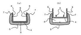
図7(a)に示すように、カバー部材5にはコ字形に形成されたベース4の外周面を収容するように凹部6が形成され、この凹部6を形成している両側壁7の内面には、前記ベース4の両側壁に形成された係合穴8と係合する係合爪9が突出して形成されており、ベース4をカバー部材5の凹部6内に押し込むことにより係合爪9の下面が係合穴8の下縁と係合することによりベース4とカバー部材5とが一体に組み付けられている。
【0005】
【発明が解決しようとする課題】
ところで、修理の際に一体に組み付けられている部品を分離する必要があり、又、異なった材料で構成されている部品は廃棄時には材料毎に分別して廃棄する必要があり、上記のように金属部品と合成樹脂部品とが係合爪9と係合穴8とを係合させることで組み付けられている場合には、簡単には分離できず分別して廃棄する作業が困難となる。また、専用工具等で無理やりにベース4とカバー部材5とを分離することは可能であるが、一般のユーザーが廃棄時に専用工具を用意することは不可能であり、更に、図7(b)に示すように分離した状態では係合爪9が破壊されてしまうので、修理等の場合には再組み付けができなくなるという問題がある。
【0006】
本発明は、金属と合成樹脂のように異なった材料で組み付けられた部品を専用の工具を使用することなく簡単に分離することができ、分別廃棄が容易にできる金属部品と合成樹脂部品とを組み付けしたステープラーを提供することを課題とする。
【0007】
【課題を解決するための手段】
上記課題を解決するため本発明のステープラーは、多数のステープルを収容するマガジンと、該マガジン内に収容されたステープルを綴り用紙に向けて打ち出すドライバを備えたハンドル部および、前記マガジンから打ち出されて綴り用紙を貫通したステープルの脚部先端部を綴り用紙の裏面に沿って屈曲させるクリンチャを備えたクリンチャアームとを各々の後端部において回動自在に支持させたステープラーにおいて、前記クリンチャアームが断面コ字形に形成された金属製部品からなるベースとこのベースの両側面と下面側を覆うように凹状の溝が形成された合成樹脂製部品からなるカバー部材とから構成され、カバー部材の両側壁内面にそれぞれ突出形成した係合爪をベースの両側壁にそれぞれ形成した係合穴に係合させることによりベースに対してカバー部材を組み付け、前記係合爪と係合穴との近傍の前記ベースの側壁とカバー部材の側壁との間に、上方に開放されてコイン等の金属片等を差し込み可能な溝を形成したことを特徴とする。
【0008】
また、請求項2のステープラーは、前記溝が、前記カバー部材の側壁の内面に形成されたことを特徴とする。
【0009】
【発明の実施の形態】
以下、図に示す実施例に従って本発明の実施の形態を説明する。図1は本発明のステープラーの実施例であり、多数のステープルを収容するマガジン10と、前記マガジン10内のステープルを綴り用紙に向けて打ち出すドライバ11を備えたハンドル部12、および前記マガジン10から打ち出されて綴り用紙を貫通したステープルの脚部先端部を綴り用紙の裏面に沿って屈曲させるクリンチャ13を備えたクリンチャアーム14がそれぞれの後端部において支持軸15によって回動自在に支持されている。
【0010】
マガジン10の前端部には収容された先頭のステープルをマガジン10の下面に配置される綴じ用紙に向けて打ち出す打出口16が形成されており、更にマガジン10内にはマガジン10内に収容されたステープルを前記打出口16に向けて押圧付勢させるプッシャ17が配置されている。プッシャ17はマガジン10内に配置されたガイドロッド18に沿って摺動自在に支持されており、プッシャバネ19によりマガジン10の前方へ向けて付勢されている。
【0011】
ハンドル部12の上面を押圧操作することによりドライバ11を介してマガジン10内のステープルが打出口16から打ち出されてマガジン10の下面に配置された綴じ用紙に向けて、綴じ用紙を貫通したステープルの脚部がクリンチャ13によって綴じ用紙の裏面に沿って折り曲げられて綴じ用紙が綴じられる。
【0012】
図2及び図3に示すように、クリンチャアーム14は、金属板材を断面がコ字形となるように折り曲げ成型して形成されたベース20とこのベース20の両側面と下面を覆うように組み付けられたカバー部材21とで構成されている。ベース20の後端部には前記支軸15により支持される枢支穴22が形成され、前端部には上面にステープル脚先端と当接してステープル脚を折り曲げるクリンチャ溝23が形成された金属材からなるクリンチャ13が一体に形成されている。前記ベース20の両側に立ち上がり形成された側壁24には側壁24を貫通した係合穴25が形成されている。
【0013】
カバー部材21は合成樹脂で形成されるとともに、内側に前記ベース20を収容するように上面に向いた凹部26が形成されており、外側はステープラーを手で操作しやすいように膨出させた曲面で形成されている。前記凹部26を形成している両側壁27の内面には、前記ベース20に形成された係合穴25と対応した部分に係合穴25と係合する係合爪28が形成されている。係合爪28は突出寸法が上側より下側が大きくなるように傾斜面29が形成されており、組み付け時にはベース20を凹部26内に押し込むことにより傾斜面29によってカバー部材21の側壁27が押し広げられて装着することができる。ベース20がカバー部材21の凹部26内に組み付けられている状態では、図4(b)に示すように係合爪28の下面と係合穴25の下縁とが当接してベース20が上方へ抜け出るのを阻止している。
【0014】
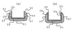
図3に示すように、カバー部材21の両側壁27の前記係合爪28が形成された近傍の両側壁27内面には凹部30が形成されており、該凹部30の深さと幅が例えばコインの厚さおよび直径と同じ程度に形成されており、図4(a)に示すように、カバー部材21がベース20に対して組み付けられた状態では、ベース20の側壁の外側面との間にコイン等を差し込める溝31が形成されるようになる。
【0015】
上記実施例によるベース20とカバー部材21とを分離する状態を、図2のA−A線及びB−B線での断面を示す図4(a)(b)及び図5に従って説明する。組み付け状態では図4(b)に示すように係合爪28が係合穴25の下側の縁と係合してカバー部材21とベース20とを一体に結合している。図4(a)に示すように凹部30によってカバー部材21の側壁27とベース20の側壁24との間には上方が開放された溝31が形成され、この溝31内にコイン状の金属片P等の一部を挿入して、この金属片Pの上部を図5(a)に示すように外側に向けて傾斜させることによってカバー部材21の両側壁27が外側に変形される。この凹部30が形成されている部分の側壁27が変形されるに伴って、図5(b)に示すように、凹部30の近傍の側壁27が連動して外側に変形されて、係合爪28が外側に広がりベース20の係合穴25から離脱されて、ベース20とカバー部材21とが分離可能となる。
【0016】
上記実施例では、カバー部材21側に凹部30を形成することによって溝31を形成するようにしているが、ベース20側に凹部を形成して溝31を形成させることもできる。更に、上記実施例では、クリンチャアーム14の前方部に係合爪28と係合穴25による組み付け構造を実施したものであるが、クリンチャアーム14の後部にも同様な係合爪と係合穴による組み付け機構を形成して、この係合爪と係合穴の近傍にも溝31を形成しても良い。更に、本発明はクリンチャアーム14に限らず、ハンドル部12における金属部品と合成樹脂部品の組み付けにも実施することが可能である。また、金属部材と樹脂製部材を分離するために、コインに替えてスクリュードライバや鍵、もしくは前記分離作業に絶え得る硬さを持つ他の樹脂片を使用してもよい。
【0017】
【発明の効果】
以上のように本発明によれば、金属製部品からなるベースと合成樹脂部品からなるカバー部材を係合爪と係合穴の係合により組み付けるようにするとともに、前記係合爪と係合穴の近傍の金属製部品と合成樹脂部品の間にコイン等の金属片等を差し込み可能な溝を形成しているので、この溝にコイン等を挿入してコインの上部をコジることにより合成樹脂部品からなるカバー部材を変形させて係合爪と係合穴との係合状態を解離させることができ、特別に解体用の専用工具を使用せずに、金属部品からなるベースと合成樹脂部品からなるカバー部材とを分離して廃棄することができる。又、修理の場合には分離により係合爪28を破損させることがないので、修理済みの部品や代え部品を再度組み付けすることが可能となる。
【図面の簡単な説明】
【図1】本発明の実施例を示すステープラーの縦断側面図
【図2】図1のステープラーのクリンチャアームの斜視図
【図3】図1のステープラーのクリンチャアーム分解した状態の斜視図
【図4】組み付けられた状態のクリンチャアームを示す断面図であり、(a)は図2におけるA−A線での断面図、(b)は図2におけるB−B線上での断面図
【図5】カバー部材とベースとを分離している状態を示すもので、(a)は図2におけるA−A線での断面図、(b)は図2におけるB−B線上での断面図
【図6】従来のステープラーのクリンチャアームを示す斜視図
【図7】図6のクリンチャアームの断面図であり、(a)は組み付けられた状態図、(b)はベースとカバー部材とを分離した状態図
【符号の説明】
10 マガジン
12 ハンドル部
13 クリンチャ
14 クリンチャアーム
20 ベース
21 カバー部材
22 枢支穴
23 クリンチャ溝
24 側壁
25 係合穴
26 凹部
27 側壁
28 係合爪
29 傾斜面
30 凹部
31 溝[0001]
BACKGROUND OF THE INVENTION
The present invention relates to a stapler capable of easily disassembling a metal part and a synthetic resin part in an assembled state at the time of repair or disposal, and capable of separating and reassembling after separation.
[0002]
[Prior art]
In the stapler for binding a plurality of binding sheets with U-shaped staples, the main parts are made of a metal material in order to maintain the precision of the parts and to maintain the durability against abrasion, etc. A synthetic resin molded part is used in combination with the metal part in order to reduce weight and cost together with these main parts.
[0003]
For example, as shown in FIG. 6, the
[0004]
As shown in FIG. 7A, the cover member 5 is formed with a recess 6 so as to accommodate the outer peripheral surface of the base 4 formed in a U-shape, and the inner surfaces of both side walls 7 forming the recess 6. Are formed with projecting
[0005]
[Problems to be solved by the invention]
By the way, it is necessary to separate parts that are assembled together at the time of repair, and parts that are made of different materials must be separated and disposed of for each material at the time of disposal. When the parts and the synthetic resin parts are assembled by engaging the
[0006]
The present invention provides a metal part and a synthetic resin part that can be easily separated without using a dedicated tool and can be easily disposed of separately. It is an object to provide an assembled stapler.
[0007]
[Means for Solving the Problems]
In order to solve the above problems, a stapler according to the present invention is a magazine that accommodates a large number of staples, a handle portion that includes a driver that ejects the staples accommodated in the magazine toward a binding sheet, and is ejected from the magazine. A clincher arm provided with a clincher arm having a clincher arm that bends the front end of the leg of the staple that has passed through the binding paper along the back surface of the binding paper, and the clincher arm has a cross section in a cross section. It is composed of a base made of a metal part formed in a U-shape and a cover member made of a synthetic resin part in which concave grooves are formed so as to cover both side surfaces and the lower surface side of the base, and both side walls of the cover member to be engaged with the engagement hole formed respectively engaging claw which respectively protrude on the inner surface to the base of the side walls Assembling the cover member to the base, between the side wall of the base wall and the cover member in the vicinity of the engagement claws and engagement holes, which can insert the metal piece or the like of the coins is opened upward A groove is formed.
[0008]
The stapler according to
[0009]
DETAILED DESCRIPTION OF THE INVENTION
Hereinafter, embodiments of the present invention will be described with reference to the examples shown in the drawings. FIG. 1 shows an embodiment of a stapler according to the present invention. A
[0010]
The front end portion of the
[0011]
By pressing the upper surface of the handle portion 12, the staples in the
[0012]
As shown in FIGS. 2 and 3, the clincher arm 14 is assembled so as to cover a
[0013]
The
[0014]
As shown in FIG. 3, a
[0015]
A state in which the
[0016]
In the above embodiment, the
[0017]
【The invention's effect】
As described above, according to the present invention, the base made of a metal part and the cover member made of a synthetic resin part are assembled by engaging the engaging claw and the engaging hole, and the engaging claw and the engaging hole are assembled. Since a groove in which a metal piece such as a coin can be inserted is formed between the metal part and the synthetic resin part in the vicinity of the synthetic resin, the coin is inserted into this groove and the upper part of the coin is kneaded and the synthetic resin The cover member made of parts can be deformed to disengage the engagement state between the engagement claw and the engagement hole, and the base made of metal parts and the synthetic resin parts can be used without using special tools for disassembly. The cover member made of can be separated and discarded. Further, in the case of repair, the engaging
[Brief description of the drawings]
1 is a longitudinal side view of a stapler according to an embodiment of the present invention. FIG. 2 is a perspective view of a clincher arm of the stapler of FIG. 1. FIG. 3 is a perspective view of the stapler of FIG. FIG. 5 is a cross-sectional view showing the clincher arm in an assembled state, in which (a) is a cross-sectional view taken along line AA in FIG. 2, and (b) is a cross-sectional view taken along line BB in FIG. FIGS. 6A and 6B show a state in which the cover member and the base are separated, wherein FIG. 6A is a cross-sectional view taken along the line AA in FIG. 2, and FIG. 6B is a cross-sectional view taken along the line BB in FIG. FIG. 7 is a cross-sectional view of a clincher arm of a conventional stapler. FIG. 7 is a cross-sectional view of the clincher arm of FIG. 6, in which (a) is an assembled state diagram, and (b) is a state diagram in which a base and a cover member are separated. [Explanation of symbols]
DESCRIPTION OF
Claims (2)
Priority Applications (1)
| Application Number | Priority Date | Filing Date | Title |
|---|---|---|---|
| JP2002014852A JP3840980B2 (en) | 2002-01-23 | 2002-01-23 | stapler |
Applications Claiming Priority (1)
| Application Number | Priority Date | Filing Date | Title |
|---|---|---|---|
| JP2002014852A JP3840980B2 (en) | 2002-01-23 | 2002-01-23 | stapler |
Publications (2)
| Publication Number | Publication Date |
|---|---|
| JP2003220574A JP2003220574A (en) | 2003-08-05 |
| JP3840980B2 true JP3840980B2 (en) | 2006-11-01 |
Family
ID=27742653
Family Applications (1)
| Application Number | Title | Priority Date | Filing Date |
|---|---|---|---|
| JP2002014852A Expired - Fee Related JP3840980B2 (en) | 2002-01-23 | 2002-01-23 | stapler |
Country Status (1)
| Country | Link |
|---|---|
| JP (1) | JP3840980B2 (en) |
-
2002
- 2002-01-23 JP JP2002014852A patent/JP3840980B2/en not_active Expired - Fee Related
Also Published As
| Publication number | Publication date |
|---|---|
| JP2003220574A (en) | 2003-08-05 |
Similar Documents
| Publication | Publication Date | Title |
|---|---|---|
| US5560529A (en) | Cartridge for electric stapler | |
| US4491261A (en) | Hand-operated stapler-punch combination | |
| US7143921B2 (en) | Staple cartridge for electric stapler | |
| US7604149B2 (en) | Effort-saving stapler | |
| US20090159637A1 (en) | Stapler having power mutliplying mechanism | |
| US7828182B2 (en) | Stapler switchable between various operation modes and switching method thereof | |
| JPH0715281U (en) | Electric stapler | |
| JP3840980B2 (en) | stapler | |
| JP5125336B2 (en) | Staple | |
| EP1582323B1 (en) | Staple-leg guide mechanism | |
| JP4135392B2 (en) | stapler | |
| JP3925634B2 (en) | stapler | |
| EP2111958B1 (en) | Staple cartridge in stapler | |
| JP4036215B2 (en) | Electric stapler | |
| JP2631355B2 (en) | stapler | |
| JP5080142B2 (en) | Stapler | |
| JP5071003B2 (en) | Stapler | |
| US6321935B1 (en) | Clip device for bending a clip plate and clipping a bundle of sheets together with the bent clip plate and method of its use | |
| EP1599317B1 (en) | Releasable staple magazine with a releasable staple forming arrangement | |
| JP4254500B2 (en) | Stapler one-touch open mechanism | |
| JP2671255B2 (en) | stapler | |
| JP2009012094A (en) | Stapler | |
| EP1829648A1 (en) | Stapling device | |
| JPH0546859Y2 (en) | ||
| JP2007136614A (en) | Stapler |
Legal Events
| Date | Code | Title | Description |
|---|---|---|---|
| A621 | Written request for application examination |
Free format text: JAPANESE INTERMEDIATE CODE: A621 Effective date: 20041227 |
|
| A977 | Report on retrieval |
Free format text: JAPANESE INTERMEDIATE CODE: A971007 Effective date: 20060425 |
|
| A131 | Notification of reasons for refusal |
Free format text: JAPANESE INTERMEDIATE CODE: A131 Effective date: 20060508 |
|
| A521 | Written amendment |
Free format text: JAPANESE INTERMEDIATE CODE: A523 Effective date: 20060620 |
|
| TRDD | Decision of grant or rejection written | ||
| A01 | Written decision to grant a patent or to grant a registration (utility model) |
Free format text: JAPANESE INTERMEDIATE CODE: A01 Effective date: 20060718 |
|
| A61 | First payment of annual fees (during grant procedure) |
Free format text: JAPANESE INTERMEDIATE CODE: A61 Effective date: 20060731 |
|
| R150 | Certificate of patent or registration of utility model |
Free format text: JAPANESE INTERMEDIATE CODE: R150 |
|
| FPAY | Renewal fee payment (event date is renewal date of database) |
Free format text: PAYMENT UNTIL: 20100818 Year of fee payment: 4 |
|
| LAPS | Cancellation because of no payment of annual fees |