EP1599317B1 - Releasable staple magazine with a releasable staple forming arrangement - Google Patents
Releasable staple magazine with a releasable staple forming arrangement Download PDFInfo
- Publication number
- EP1599317B1 EP1599317B1 EP04706905A EP04706905A EP1599317B1 EP 1599317 B1 EP1599317 B1 EP 1599317B1 EP 04706905 A EP04706905 A EP 04706905A EP 04706905 A EP04706905 A EP 04706905A EP 1599317 B1 EP1599317 B1 EP 1599317B1
- Authority
- EP
- European Patent Office
- Prior art keywords
- staple
- container
- forming
- magazine
- arrangement
- Prior art date
- Legal status (The legal status is an assumption and is not a legal conclusion. Google has not performed a legal analysis and makes no representation as to the accuracy of the status listed.)
- Expired - Lifetime
Links
- 238000005452 bending Methods 0.000 claims abstract description 5
- 239000007769 metal material Substances 0.000 claims description 6
- 230000008901 benefit Effects 0.000 description 2
- 238000004519 manufacturing process Methods 0.000 description 2
- 230000006378 damage Effects 0.000 description 1
- 230000003993 interaction Effects 0.000 description 1
- 239000000463 material Substances 0.000 description 1
- 239000002184 metal Substances 0.000 description 1
- 238000000926 separation method Methods 0.000 description 1
- 239000002699 waste material Substances 0.000 description 1
Images


Classifications
-
- B—PERFORMING OPERATIONS; TRANSPORTING
- B27—WORKING OR PRESERVING WOOD OR SIMILAR MATERIAL; NAILING OR STAPLING MACHINES IN GENERAL
- B27F—DOVETAILED WORK; TENONS; SLOTTING MACHINES FOR WOOD OR SIMILAR MATERIAL; NAILING OR STAPLING MACHINES
- B27F7/00—Nailing or stapling; Nailed or stapled work
- B27F7/17—Stapling machines
- B27F7/38—Staple feeding devices
Definitions
- the present invention relates to a staple magazine for mounting to a stapler used to staple together a workpiece, primarily a sheaf of papers, the said staple magazine comprising a container, in which elongated staple blanks in the form of a strip are stored, and a staple forming arrangement comprising a forming punch, which bends the elongated staple blanks into the shape of a staple over a forming block, and a drive punch with which the staple blanks which have been bent into staple shape for stapling the workpiece are driven into the said workpiece, the staple blanks stored in strip form being fed by a feeder plate to a forming block along a feed path incorporated in the container, the forming punch and drive punch being driven in a reciprocating bending and drive movement by a drive arrangement incorporated in the stapler, and the staple magazine being replaced when the staples have been used.
- the invention relates to a container designed to form part of a staple magazine, which staple magazine is designed to be mounted to a stapler used to staple together a workpiece, primarily a sheaf of papers, the said staple magazine comprising a container, in which elongated staple blanks in the form of a strip are stored, and a staple forming arrangement comprising a forming punch, which bends the elongated staple blanks into the shape of a staple over a forming block, and a drive punch with which the staple blanks which have been bent into staple shape for stapling the workpiece are driven into the said workpiece, the staple blanks stored in strip form being fed by a feeder plate to a forming block along a feed path included in the container, the forming punch and drive punch being driven in a reciprocating bending and drive movement by a drive arrangement incorporated in the stapler, and the staple magazine being replaced when the staples have been used.
- a staple magazine or a container of the type described above is already known and, for example, is described in the applicant's own patent SE 9201230-1 and US 5,794,833 .
- the disadvantage of these earlier devices is that the container and staple forming arrangement are permanently attached to each other in a manner which prevents their separation from each other without destruction. This means that when the staple magazine has been emptied of its contents, both the container and staple forming arrangement must be replaced, which is unnecessarily expensive and represents a significant waste.
- a final disadvantage is that since the feeder plate is located in the stapler, it must be compatible with every magazine or container installed in the stapler to ensure satisfactory operation and the magazines must, therefore, be manufactured to a high degree of precision.
- US 6,050,471 relates to an electric stapler in which a staple magazine cannot be replaced when the staples have been used.
- the present invention overcomes the aforementioned disadvantages by means of a staple magazine of the type described in the introduction, which is characterised by the features of the characterizing portion of claim 1
- the present invention may further be characterised in that the said connecting devices are provided with one or more openings/cavities in the staple forming arrangement and catching devices in the container corresponding to the openings/cavities, which catching devices are engaged in the openings/cavities to ensure secure connection between the container and staple forming arrangement.
- the present invention may yet further be characterised in that the forming block is integrated with the container.
- the present invention may even yet further be characterised in that the inner walls of the feed path are made of a metallic material.
- the present invention may further even yet further be characterised in that the width of the feed path is negligibly wider than that of the staple strip.
- the present invention may also be characterised in that the feeder plate is attached to the container part.
- the present invention overcomes the aforementioned disadvantages by means of a container of the type described in the introduction, which is characterised by the features of the charaterizing portion of claim 7.
- the invention may further be characterised in that the said connecting devices are provided with one or more openings/cavities in the staple forming arrangement and catching devices in the container corresponding to the openings/cavities, which catching devices are engaged in the openings/cavities to ensure secure connection between the container and staple forming arrangement.
- the invention may yet further be characterised in that the forming block is integral with the container.
- the invention may further even yet further be characterised in that the width of the feed path is negligibly wider than that of the staple strip.
- the invention may also be characterised in that the feeder plate is attached to the container part.
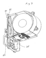
- Fig. 1 is a schematic view of a stapler 1 comprising a base part 2 and a stapler head 4, which is pivotably connected to the base part by means of a pivot pin 3.
- the base part is provided with an anvil surface 5 on which the workpiece 6 to be stapled is placed.
- the stapler head houses a staple magazine 7 comprising a container 8 and a staple forming arrangement 9.
- the container contains staple blanks 10 which, in known manner, are joined side by side to form a staple strip 11, see Fig. 10 , which is stored in the form of a reel 12.
- the stapler is also provided with a drive arrangement 13 comprising a drive motor 14 which, by means of a linkage 15, drives the drive arms 16, only one of which is shown in the figures, which arms drive the stapler head and staple forming arrangement in a reciprocating stapling movement as indicated by the double arrow P.
- the stapler head is further provided with a feed device 17 which, as will be described later, acts on a feeder plate which feeds the staple strip 11 forward during a stapling movement.
- the staple forming arrangement 9 comprises a base plate 18 provided, in known manner, with a forming punch 19 with an integral drive punch 20.
- the forming punch is provided with cutouts 21 which engage with and are acted upon by the drive arms 16, not shown in the figures, which arms causing the forming punch to be driven in a reciprocating stapling movement.
- the base plate 18 is provided with upper cavities 22 and lower openings 23.
- the base plate is further provided with a shackle 24 comprising a first shackle side 25 and a second shackle side 26.
- the first shackle side consists of an arrangement 27 whose function is to capture and guide the legs of the staple after the staple blank has been bent into the form of a staple. Since this function is not of significance to the present invention, it will not be described further.
- the second shackle side 26 is provided with two legs 28 and 29, each provided with a projection, 30 and 31 respectively.
- the shackle is fitted to the base plate 18 by positioning the shackle sides astride the base plate and, when the shackle is pushed in fully, the bottom 24 of the shackle abuts an edge area 33 of the base plate. The shackle is held securely in position by the fact that the bottom of the shackle is, in known manner, designed to clamp onto the edge area 33.
- the projections 30 and 31 will be positioned partly in the areas of the respective openings 23 and the function of this relationship will be described below.
- the shackle 24 is guided laterally relative to the base plate by means of studs (not shown in the figures) located on the side on which the legs 28 and 29 are placed and against which the legs 28 and 29 are guided.
- the container 8 is provided with upper catches 34 and lower catches 35. The relative location of the catches is such that they engage in the cavities 22 and openings 23 respectively.
- the shackle 24 is moved to the position shown in Fig.
- the arrangement 9 is tilted relative to the container 8 and the catches 34 are engaged in the cavities 22, see Fig. 7 , following which the container and arrangement are fitted together as shown in Fig. 8 , in which the catches 35 are engaged respectively in the openings 23.
- the catches 34 with their respective undersides 36, are each in contact with a respective edge side 37 of the cavities 22, and each respective upper side 38 of the catches 35 is in contact with a respective edge side 39 of the openings 23.
- the shackle 24 is then moved to the position shown in Fig.
- Figs. 6 , 10 and 11 show the container 8, in which the staple strip reel 12 comprising the staple strip 11 is housed.
- the container 8 is provided with a first rim 40 and a second rim 41, which rims extend essentially in the same direction as the longitudinal direction of the staple strip as indicated by the arrow L in Fig. 10 .
- Extending between the rims 40 and 41 is a plate 42 provided with spring clips 43 with which the plate is clipped to the rims 40 and 41 respectively.
- the plate 42 is provided with a feed path 44 along which the staple strip 11 is fed.
- the width B of the feed path is limited laterally by integral flanks 45, which are in close proximity to the respective sides 46 and 47 of the staple strip.
- the plate 42 is also provided with a forming block 48 over which the staple blanks 10 are bent in a manner which will be described below.
- the mid-section 49 of the plate 42 is provided with a raised area whose edges 50 extend in the longitudinal direction of the staple strip.
- a feed plate 51 provided with guide pins 52, which interact with the raised edges 50, is positioned between the plate 42 and the staple strip 11. The feed plate 51 can be moved in a reciprocating forward-backward movement along the staple strip 11.
- the feed plate is fed forward by the feeder device 17, which is shown only schematically in Fig. 6 , and in the direction opposite to the forward direction by interaction between the forming punch 19 and the contact arms 53 on the feed plate, in a manner which will be described below.
- the feed plate is provided with spring tabs 54, which spring downward when the feed plate is moved backward by the forming punch and grip the staple strip 11 when the plate is fed forward by the feeder device, resulting in forward feeding of the staple blanks.
- FIG. 12 A sequence in which a staple blank 10 is bent into the shape of a finished staple over a forming block 48 will hereinafter be described with reference to Figs. 12-14 , in which the container 8 is shown essentially from the side connected to the staple forming arrangement and in which the forming punch 19 is also shown.
- a staple blank 10 In the initial position shown in Fig. 12 , a staple blank 10 is shown fed forward to a position in which it is located over the forming block 48. Since, in this position, the staple blank is guided by the flanks 45, and since the distance between the flanks is negligibly greater than the length of the staple blank 10, the staple blank is centred relative to the forming block 48.
- the staple blanks cannot score the flanks, with the risk that the staple blanks may be displaced off-centre relative to the forming block.
- the forming punch 19 has been driven downward by the drive arms 16, which are not shown in the figures, and have started to bend the staple blank, while the forming punch is in contact with the contact arms 53 on the feed plate, which is thereby moved backward.
- the forming punch 19 has moved to its lowermost position and the staple blank 10 has been bent into the shape of a staple over the forming block 48. The forming punch is then returned to the position shown in Fig. 12 and contact between the forming punch 19 and contact arms 53 is interrupted, following which the feeder device feeds a new staple blank to the forming block.
Abstract
Description
- The present invention relates to a staple magazine for mounting to a stapler used to staple together a workpiece, primarily a sheaf of papers, the said staple magazine comprising a container, in which elongated staple blanks in the form of a strip are stored, and a staple forming arrangement comprising a forming punch, which bends the elongated staple blanks into the shape of a staple over a forming block, and a drive punch with which the staple blanks which have been bent into staple shape for stapling the workpiece are driven into the said workpiece, the staple blanks stored in strip form being fed by a feeder plate to a forming block along a feed path incorporated in the container, the forming punch and drive punch being driven in a reciprocating bending and drive movement by a drive arrangement incorporated in the stapler, and the staple magazine being replaced when the staples have been used.
- In accordance with another aspect of the present invention the invention relates to a container designed to form part of a staple magazine, which staple magazine is designed to be mounted to a stapler used to staple together a workpiece, primarily a sheaf of papers, the said staple magazine comprising a container, in which elongated staple blanks in the form of a strip are stored, and a staple forming arrangement comprising a forming punch, which bends the elongated staple blanks into the shape of a staple over a forming block, and a drive punch with which the staple blanks which have been bent into staple shape for stapling the workpiece are driven into the said workpiece, the staple blanks stored in strip form being fed by a feeder plate to a forming block along a feed path included in the container, the forming punch and drive punch being driven in a reciprocating bending and drive movement by a drive arrangement incorporated in the stapler, and the staple magazine being replaced when the staples have been used.
- A staple magazine or a container of the type described above is already known and, for example, is described in the applicant's own patent
SE 9201230-1 US 5,794,833 . However, the disadvantage of these earlier devices is that the container and staple forming arrangement are permanently attached to each other in a manner which prevents their separation from each other without destruction. This means that when the staple magazine has been emptied of its contents, both the container and staple forming arrangement must be replaced, which is unnecessarily expensive and represents a significant waste. - Another disadvantage of the earlier devices is that they are not equipped with a forming block, which is instead located in the stapler. This means that the staple magazine or the container must be mounted accurately relative to the forming block, which may be difficult and at the same time present a significant risk that the forming block will become worn following a number of magazine replacements, which may lead to incomplete forming of the staples.
- Yet another disadvantage is that since the feed path is made of a plastic material and the staple blanks are made of metal, a large clearance must be provided between the inner walls of the feed path and the sides of the staple strip to ensure that the staple blank do not jam against the inner walls when the blanks are fed forward. This means, however, that staple blanks can become displaced laterally relative to the forming block, causing the blanks to be bent into an unsymmetrical staple shape.
- A final disadvantage is that since the feeder plate is located in the stapler, it must be compatible with every magazine or container installed in the stapler to ensure satisfactory operation and the magazines must, therefore, be manufactured to a high degree of precision.
-
US 6,050,471 relates to an electric stapler in which a staple magazine cannot be replaced when the staples have been used. - Thus, there exists a need to manufacture a magazine or a container of such design that the complete magazine need not be disposed of when all of the staples have been used.
- There exists, further, a need for a magazine or a container provided with a forming block of such design that it does not become worn to a point at which the quality of staple forming becomes unacceptable.
- There exists, yet further, a need to provide a magazine or a container with a feed path which is so narrow relative to the staple strip that there is no risk of bending a staple into an unsymmetrical shape.
- There exists, finally, a need to provide a magazine or a container of such design that it is unnecessary to adjust the staple magazine relative to the feeder plate when the staple magazine is installed in the stapler.
- According to the present invention, it is suggested to provide a staple magazine having the features of independent claim 1.
- The present invention overcomes the aforementioned disadvantages by means of a staple magazine of the type described in the introduction, which is characterised by the features of the characterizing portion of claim 1
- The present invention may further be characterised in that the said connecting devices are provided with one or more openings/cavities in the staple forming arrangement and catching devices in the container corresponding to the openings/cavities, which catching devices are engaged in the openings/cavities to ensure secure connection between the container and staple forming arrangement.
- The present invention may yet further be characterised in that the forming block is integrated with the container.
- The present invention may even yet further be characterised in that the inner walls of the feed path are made of a metallic material.
- The present invention may further even yet further be characterised in that the width of the feed path is negligibly wider than that of the staple strip.
- The present invention may also be characterised in that the feeder plate is attached to the container part.
- It is also suggested to provide a container having the features of
independent claim 7. - In accordance with this another aspect of the present invention, the present invention overcomes the aforementioned disadvantages by means of a container of the type described in the introduction, which is characterised by the features of the charaterizing portion of
claim 7. - In accordance with said other aspect, the invention may further be characterised in that the said connecting devices are provided with one or more openings/cavities in the staple forming arrangement and catching devices in the container corresponding to the openings/cavities, which catching devices are engaged in the openings/cavities to ensure secure connection between the container and staple forming arrangement.
- In accordance with said other aspect, the invention may yet further be characterised in that the forming block is integral with the container.
- In accordance with said other aspect the invention may even yet further be characterised in that the inner walls of the feed path are made of a metallic material
- In accordance with said other aspect the invention may further even yet further be characterised in that the width of the feed path is negligibly wider than that of the staple strip.
- In accordance with said other aspect the invention may also be characterised in that the feeder plate is attached to the container part.
- The invention will hereinafter be described with reference to a preferred embodiment, which is shown in the appended figures, of which:
-
Fig. 1 is a schematic view of a stapler; -
Fig. 2 shows a staple magazine in accordance with the present invention, in which the container and staple forming arrangement have been separated; -
Fig. 3 is a view corresponding toFig. 2 , with a part which is essential for connecting the container and staple forming arrangement together shown exposed; -
Fig. 4 is a view in which the container and staple forming arrangement have been assembled together, but have not yet been connected securely to each other; -
Fig. 5 is a view corresponding toFig. 4 in which the parts have been connected securely to each other; -
Fig. 6 is a view showing the staple magazine container; -
Fig. 7 is a view in which the side facing the viewer has been made transparent and in which connection of the container to the staple forming arrangement has been commenced. -
Fig. 8 is a view corresponding toFig. 4 in which the side facing the viewer has been made transparent; -
Fig. 9 is a view corresponding toFig. 5 in which the side facing the viewer has been made transparent; -
Fig. 10 is a view of the container, with parts essential to the invention shown exposed; -
Fig. 11 shows the container as viewed from the side which is to be connected to the staple forming arrangement; -
Figs. 12-14 show a sequence in which a staple blank is bent into the shape of a staple by the forming punch. -
Fig. 1 is a schematic view of a stapler 1 comprising abase part 2 and astapler head 4, which is pivotably connected to the base part by means of apivot pin 3. The base part is provided with ananvil surface 5 on which theworkpiece 6 to be stapled is placed. The stapler head houses astaple magazine 7 comprising acontainer 8 and astaple forming arrangement 9. The container containsstaple blanks 10 which, in known manner, are joined side by side to form a staple strip 11, seeFig. 10 , which is stored in the form of areel 12. The stapler is also provided with adrive arrangement 13 comprising adrive motor 14 which, by means of alinkage 15, drives thedrive arms 16, only one of which is shown in the figures, which arms drive the stapler head and staple forming arrangement in a reciprocating stapling movement as indicated by the double arrow P. The stapler head is further provided with afeed device 17 which, as will be described later, acts on a feeder plate which feeds the staple strip 11 forward during a stapling movement. - The
container 8 and thestaple forming arrangement 9 will hereinafter be described in detail with reference toFigs. 2-9 . Thestaple forming arrangement 9 comprises abase plate 18 provided, in known manner, with a formingpunch 19 with anintegral drive punch 20. The forming punch is provided withcutouts 21 which engage with and are acted upon by thedrive arms 16, not shown in the figures, which arms causing the forming punch to be driven in a reciprocating stapling movement. Thebase plate 18 is provided withupper cavities 22 andlower openings 23. The base plate is further provided with ashackle 24 comprising afirst shackle side 25 and asecond shackle side 26. The first shackle side consists of anarrangement 27 whose function is to capture and guide the legs of the staple after the staple blank has been bent into the form of a staple. Since this function is not of significance to the present invention, it will not be described further. Thesecond shackle side 26 is provided with twolegs base plate 18 by positioning the shackle sides astride the base plate and, when the shackle is pushed in fully, thebottom 24 of the shackle abuts anedge area 33 of the base plate. The shackle is held securely in position by the fact that the bottom of the shackle is, in known manner, designed to clamp onto theedge area 33. When the shackle is pushed in fully to the position shown inFig. 5 , theprojections respective openings 23 and the function of this relationship will be described below. Theshackle 24 is guided laterally relative to the base plate by means of studs (not shown in the figures) located on the side on which thelegs legs container 8 is provided withupper catches 34 and lower catches 35. The relative location of the catches is such that they engage in thecavities 22 andopenings 23 respectively. To connect thestaple forming arrangement 9 to thecontainer 8, theshackle 24 is moved to the position shown inFig. 2 , thearrangement 9 is tilted relative to thecontainer 8 and thecatches 34 are engaged in thecavities 22, seeFig. 7 , following which the container and arrangement are fitted together as shown inFig. 8 , in which thecatches 35 are engaged respectively in theopenings 23. In this position, thecatches 34, with theirrespective undersides 36, are each in contact with arespective edge side 37 of thecavities 22, and each respectiveupper side 38 of thecatches 35 is in contact with arespective edge side 39 of theopenings 23. This ensures that thecontainer 8 and thestaple forming arrangement 9 cannot move relative to each other in the direction indicated by the double arrow U inFig. 8 . Theshackle 24 is then moved to the position shown inFig. 9 , causing theprojections respective openings 23 in the base plate, thereby restricting the openings and ensuring that thecatches 35 cannot be displaced from theopenings 23, with the result that secure connection is established between the container and staple forming arrangement. To separate the container and staple forming arrangement, theshackle 24 is moved to the position shown inFig. 8 , whereupon the catches are disengaged from the openings and cavities, releasing the container from the staple forming arrangement and enabling it to be replaced by a new, full container. -
Figs. 6 ,10 and11 show thecontainer 8, in which thestaple strip reel 12 comprising the staple strip 11 is housed. Thecontainer 8 is provided with afirst rim 40 and a second rim 41, which rims extend essentially in the same direction as the longitudinal direction of the staple strip as indicated by the arrow L inFig. 10 . Extending between therims 40 and 41 is aplate 42 provided withspring clips 43 with which the plate is clipped to therims 40 and 41 respectively. Theplate 42 is provided with afeed path 44 along which the staple strip 11 is fed. The width B of the feed path is limited laterally byintegral flanks 45, which are in close proximity to therespective sides plate 42 is also provided with a formingblock 48 over which thestaple blanks 10 are bent in a manner which will be described below. The mid-section 49 of theplate 42 is provided with a raised area whoseedges 50 extend in the longitudinal direction of the staple strip. Afeed plate 51 provided with guide pins 52, which interact with the raisededges 50, is positioned between theplate 42 and the staple strip 11. Thefeed plate 51 can be moved in a reciprocating forward-backward movement along the staple strip 11. The feed plate is fed forward by thefeeder device 17, which is shown only schematically inFig. 6 , and in the direction opposite to the forward direction by interaction between the formingpunch 19 and thecontact arms 53 on the feed plate, in a manner which will be described below. The feed plate is provided withspring tabs 54, which spring downward when the feed plate is moved backward by the forming punch and grip the staple strip 11 when the plate is fed forward by the feeder device, resulting in forward feeding of the staple blanks. - A sequence in which a staple blank 10 is bent into the shape of a finished staple over a forming
block 48 will hereinafter be described with reference toFigs. 12-14 , in which thecontainer 8 is shown essentially from the side connected to the staple forming arrangement and in which the formingpunch 19 is also shown. In the initial position shown inFig. 12 , a staple blank 10 is shown fed forward to a position in which it is located over the formingblock 48. Since, in this position, the staple blank is guided by theflanks 45, and since the distance between the flanks is negligibly greater than the length of the staple blank 10, the staple blank is centred relative to the formingblock 48. Furthermore, since theflanks 45 consist of a metallic material, the staple blanks cannot score the flanks, with the risk that the staple blanks may be displaced off-centre relative to the forming block. InFig. 13 , the formingpunch 19 has been driven downward by thedrive arms 16, which are not shown in the figures, and have started to bend the staple blank, while the forming punch is in contact with thecontact arms 53 on the feed plate, which is thereby moved backward. InFig. 14 , the formingpunch 19 has moved to its lowermost position and the staple blank 10 has been bent into the shape of a staple over the formingblock 48. The forming punch is then returned to the position shown inFig. 12 and contact between the formingpunch 19 and contactarms 53 is interrupted, following which the feeder device feeds a new staple blank to the forming block. - The present invention is obviously not limited by the foregoing description, but only by the claims stated below.
Claims (12)
- Staple magazine (7) for mounting to a stapler (1) used to staple together a workpiece (6), primarily a sheaf of papers, the said staple magazine comprising a container (8), in which elongated staple blanks (10) in the form of a strip (11) are stored, and a staple forming arrangement (9) comprising a forming punch (19), which bends the elongated staple blanks into the shape of a staple over a forming block (48), and a drive punch (20) with which the staple blanks which have been bent into staple shape for stapling the workpiece are driven into the said workpiece, the staple blanks stored in strip form being fed by a feeder plate (51) to a forming block (48) along a feed path (44) incorporated in the container, and the forming punch and drive punch being driven in a reciprocating bending and drive movement (P) by a drive arrangement (13-16) incorporated in the stapler, and the staple magazine being replaced when the staples have been used CHARACTERISED IN THAT the container (8) and the staple forming arrangement (9) are connected to each other by means of releasable connecting devices (22, 23, 34, 35), wherein a securing means (24) is provided which is moveable between a position in which a secure connection between container and staple forming arrangement is established, and a position releasing the container from the staple forming arrangement.
- Staple magazine (7) in accordance with claim 1 CHARACTERISED IN THAT the connecting devices (22, 23, 34, 35) are provided with one or more openings/cavities (22, 23) in the staple forming arrangement (9) and catching devices (34, 35) in the container (8) corresponding to the openings/cavities, which catching devices are engaged in the openings/cavities to ensure secure connection between the container and the staple forming arrangement.
- Staple magazine (7) in accordance with claim 1 or 2 CHARACTERISED IN THAT the forming block (48) belongs to the container (8).
- Staple magazine (7) in accordance with any of the foregoing claims CHARACTERISED IN THAT the inner walls (45) of the feed path (44) are of a metallic material.
- Staple magazine (7) in accordance with claim 4 CHARACTERISED IN THAT the width (B) of the feed path (44) is negligibly greater than the width (b) of the staple strip (11).
- Staple magazine (7) in accordance with any of the foregoing claims CHARACTERISED IN THAT the feeder plate (51) is attached to the container (8).
- Container (8) designed to form a part of a staple magazine (7), which staple magazine comprising a staple forming arrangement (9) is designed to be mounted to a stapler (1) used to staple together a workpiece (6), primarily a sheaf of papers, wherein elongated staple blanks (10) in the form of a strip (11) are stored in the container (8), the staple blanks stored in strip form being fed by a feeder plate (51) to a forming block (48) along a feed path (44) incorporated in the container, CHARACTERISED IN THAT the container (8) is releasably connectable to the staple forming arrangement (9) by releasable connecting devices (22, 23, 34, 35), wherein the container is adapted for being securely connected to the staple forming arrangement by a securing means (24), and for being released from the staple forming arrangement by said securing means (24).
- Container (8) in accordance with claim 7, CHARACTERISED IN THAT the connecting devices (22, 23, 34, 35) are provided with catching devices (34,35) in the container (8) corresponding to openings/cavities of a staple forming arrangement (9) of the staple magazine (7), which catching devices are capable of being engaged in the openings/cavities to ensure secure connection between the container and the staple forming arrangement.
- Container (8) in accordance with claim 7 or 8 CHARACTERISED IN THAT the forming block (48) belongs to the container (8).
- Container (8) in accordance with any of claims 7-9 CHARACTERISED IN THAT the inner walls (45) of the feed path (44) are of a metallic material.
- Container (8) in accordance with claim 10 CHARACTERISED IN THAT the width (B) of the feed path (44) is negligibly greater than the width (b) of the staple strip (11).
- Container (8) in accordance with any of claim 7-11 CHARACTERISED IN THAT the feeder plate (51) is attached to the container (8).
Applications Claiming Priority (3)
| Application Number | Priority Date | Filing Date | Title |
|---|---|---|---|
| SE0300298A SE523848C2 (en) | 2003-02-06 | 2003-02-06 | Staple magazine for mounting to stapler, has container which store elongated staple blanks and staple forming arrangement comprising forming and drive punches, and both connected to each other by releasable connecting devices |
| SE0300298 | 2003-02-06 | ||
| PCT/SE2004/000120 WO2004069486A1 (en) | 2003-02-06 | 2004-01-30 | Releasable staple magazine with a releasable staple forming arrangement |
Publications (2)
| Publication Number | Publication Date |
|---|---|
| EP1599317A1 EP1599317A1 (en) | 2005-11-30 |
| EP1599317B1 true EP1599317B1 (en) | 2011-06-29 |
Family
ID=20290312
Family Applications (1)
| Application Number | Title | Priority Date | Filing Date |
|---|---|---|---|
| EP04706905A Expired - Lifetime EP1599317B1 (en) | 2003-02-06 | 2004-01-30 | Releasable staple magazine with a releasable staple forming arrangement |
Country Status (7)
| Country | Link |
|---|---|
| US (1) | US7469810B2 (en) |
| EP (1) | EP1599317B1 (en) |
| JP (1) | JP4563995B2 (en) |
| CN (1) | CN100418704C (en) |
| AT (1) | ATE514530T1 (en) |
| SE (1) | SE523848C2 (en) |
| WO (1) | WO2004069486A1 (en) |
Families Citing this family (4)
| Publication number | Priority date | Publication date | Assignee | Title |
|---|---|---|---|---|
| SE0601831L (en) * | 2006-09-07 | 2007-06-26 | Isaberg Rapid Ab | Feed means in a staple cassette intended for a stapler |
| SE0701907L (en) * | 2007-08-24 | 2008-05-20 | Isaberg Rapid Ab | Feed means in a staple cartridge intended for a stapler that reduces feed errors |
| JP5104484B2 (en) * | 2008-04-01 | 2012-12-19 | マックス株式会社 | Staple width adjustment method for stapler |
| JP6870281B2 (en) * | 2016-10-31 | 2021-05-12 | マックス株式会社 | Stapler |
Family Cites Families (19)
| Publication number | Priority date | Publication date | Assignee | Title |
|---|---|---|---|---|
| US3009156A (en) * | 1956-05-18 | 1961-11-21 | Inv S Man Corp | Industrial tacker |
| US4573625A (en) * | 1982-10-04 | 1986-03-04 | Swingline Inc. | Staple forming and driving machine |
| US4588121A (en) * | 1983-06-23 | 1986-05-13 | Swingline, Inc. | Belt cartridge for staple forming and driving machine and method |
| US4583276A (en) * | 1983-06-23 | 1986-04-22 | Swingline, Inc. | Method of forming and driving staples |
| US5273199A (en) * | 1990-03-07 | 1993-12-28 | Xerox Corporation | Staple cartridge |
| US5346114A (en) * | 1990-09-14 | 1994-09-13 | Max Co., Ltd. | Electric stapler with unmovably fixed magazine |
| SE469112B (en) * | 1992-04-16 | 1993-05-17 | Isaberg Ab | CASE FOR USE IN A PAPER |
| DE69300550T2 (en) * | 1992-07-10 | 1996-03-28 | Max Co Ltd | Motorized stapler. |
| EP0637487B1 (en) * | 1993-08-04 | 1997-10-29 | Max Co., Ltd. | Cartridge for electric stapler |
| GB9501774D0 (en) * | 1995-01-31 | 1995-03-22 | Reddiplex Ltd | Method of extruding two or more materials |
| DE69727761T2 (en) * | 1996-10-23 | 2004-08-05 | Max Co. Ltd. | Electric stapler |
| US6039230A (en) * | 1997-11-19 | 2000-03-21 | Max Co., Ltd. | Roll staple and staple cartridge storing the same |
| JP2000167782A (en) * | 1998-12-02 | 2000-06-20 | Nisca Corp | Staple package for stapler and stapler device |
| JP3582418B2 (en) * | 1999-09-30 | 2004-10-27 | マックス株式会社 | Cover mechanism for electric stapler cartridge |
| JP3687461B2 (en) * | 2000-02-02 | 2005-08-24 | マックス株式会社 | Staple pop-up prevention mechanism of staple cartridge |
| JP2001347472A (en) * | 2000-06-05 | 2001-12-18 | Nisca Corp | Stapler device |
| JP2002200575A (en) * | 2000-12-28 | 2002-07-16 | Nisca Corp | Staple cartridge and stapler provided with the same |
| JP4419335B2 (en) * | 2001-03-12 | 2010-02-24 | マックス株式会社 | Staple cartridge system |
| SE0102443L (en) * | 2001-07-09 | 2002-07-16 | Isaberg Rapid Ab | Back locking device in a staple magazine |
-
2003
- 2003-02-06 SE SE0300298A patent/SE523848C2/en not_active IP Right Cessation
-
2004
- 2004-01-30 US US10/544,810 patent/US7469810B2/en not_active Expired - Lifetime
- 2004-01-30 CN CNB2004800020974A patent/CN100418704C/en not_active Expired - Lifetime
- 2004-01-30 WO PCT/SE2004/000120 patent/WO2004069486A1/en active Application Filing
- 2004-01-30 JP JP2006502786A patent/JP4563995B2/en not_active Expired - Lifetime
- 2004-01-30 AT AT04706905T patent/ATE514530T1/en not_active IP Right Cessation
- 2004-01-30 EP EP04706905A patent/EP1599317B1/en not_active Expired - Lifetime
Also Published As
| Publication number | Publication date |
|---|---|
| SE0300298L (en) | 2004-05-25 |
| ATE514530T1 (en) | 2011-07-15 |
| US20060255087A1 (en) | 2006-11-16 |
| EP1599317A1 (en) | 2005-11-30 |
| WO2004069486A1 (en) | 2004-08-19 |
| CN100418704C (en) | 2008-09-17 |
| SE0300298D0 (en) | 2003-02-06 |
| JP2006517152A (en) | 2006-07-20 |
| JP4563995B2 (en) | 2010-10-20 |
| CN1735484A (en) | 2006-02-15 |
| SE523848C2 (en) | 2004-05-25 |
| US7469810B2 (en) | 2008-12-30 |
Similar Documents
| Publication | Publication Date | Title |
|---|---|---|
| EP2361786B1 (en) | Interlinked staples and staple cartridge | |
| EP0636058B1 (en) | Cassette for use in a stapler | |
| EP0904904B1 (en) | Staple clinching mechanism in stapler | |
| EP1426155A1 (en) | Staple detection mechanism of electric stapler | |
| EP0995561B1 (en) | Staple leg cutting mechanism for an electric stapler | |
| GB2130519A (en) | Staple forming and driving machine | |
| US7621433B2 (en) | Stapler | |
| EP2246162B1 (en) | Stapler | |
| WO2006009015A1 (en) | Stapler and stapler cartridge | |
| EP1599317B1 (en) | Releasable staple magazine with a releasable staple forming arrangement | |
| US6702172B1 (en) | Staple driver with convex edge and pointed protrusions at the ends | |
| JP5282663B2 (en) | Staple cartridge and refill | |
| KR101036389B1 (en) | Cartridge | |
| US7021513B2 (en) | Staple forming arrangement in a stapler | |
| JP4927713B2 (en) | Stapler | |
| JP2019181903A (en) | cartridge | |
| JP4736296B2 (en) | Bundling device | |
| JP4036215B2 (en) | Electric stapler | |
| EP0051447A1 (en) | A stapling apparatus | |
| WO2008030153A1 (en) | Feed means in a staple cassette intended for a stapler | |
| JP4650611B2 (en) | Stapler clincher mechanism | |
| JPH0453909Y2 (en) | ||
| JP2554548Y2 (en) | Stippler | |
| WO2009029042A1 (en) | Feed member for a staple magazine of a stapler in order to prevent jamming |
Legal Events
| Date | Code | Title | Description |
|---|---|---|---|
| PUAI | Public reference made under article 153(3) epc to a published international application that has entered the european phase |
Free format text: ORIGINAL CODE: 0009012 |
|
| 17P | Request for examination filed |
Effective date: 20050902 |
|
| AK | Designated contracting states |
Kind code of ref document: A1 Designated state(s): AT BE BG CH CY CZ DE DK EE ES FI FR GB GR HU IE IT LI LU MC NL PT RO SE SI SK TR |
|
| AX | Request for extension of the european patent |
Extension state: AL LT LV MK |
|
| DAX | Request for extension of the european patent (deleted) | ||
| 17Q | First examination report despatched |
Effective date: 20091127 |
|
| GRAP | Despatch of communication of intention to grant a patent |
Free format text: ORIGINAL CODE: EPIDOSNIGR1 |
|
| GRAS | Grant fee paid |
Free format text: ORIGINAL CODE: EPIDOSNIGR3 |
|
| GRAA | (expected) grant |
Free format text: ORIGINAL CODE: 0009210 |
|
| AK | Designated contracting states |
Kind code of ref document: B1 Designated state(s): AT BE BG CH CY CZ DE DK EE ES FI FR GB GR HU IE IT LI LU MC NL PT RO SE SI SK TR |
|
| REG | Reference to a national code |
Ref country code: GB Ref legal event code: FG4D |
|
| REG | Reference to a national code |
Ref country code: CH Ref legal event code: EP |
|
| REG | Reference to a national code |
Ref country code: IE Ref legal event code: FG4D |
|
| REG | Reference to a national code |
Ref country code: DE Ref legal event code: R096 Ref document number: 602004033270 Country of ref document: DE Effective date: 20110818 |
|
| REG | Reference to a national code |
Ref country code: NL Ref legal event code: VDEP Effective date: 20110629 |
|
| PG25 | Lapsed in a contracting state [announced via postgrant information from national office to epo] |
Ref country code: SE Free format text: LAPSE BECAUSE OF FAILURE TO SUBMIT A TRANSLATION OF THE DESCRIPTION OR TO PAY THE FEE WITHIN THE PRESCRIBED TIME-LIMIT Effective date: 20110629 |
|
| PG25 | Lapsed in a contracting state [announced via postgrant information from national office to epo] |
Ref country code: SI Free format text: LAPSE BECAUSE OF FAILURE TO SUBMIT A TRANSLATION OF THE DESCRIPTION OR TO PAY THE FEE WITHIN THE PRESCRIBED TIME-LIMIT Effective date: 20110629 Ref country code: GR Free format text: LAPSE BECAUSE OF FAILURE TO SUBMIT A TRANSLATION OF THE DESCRIPTION OR TO PAY THE FEE WITHIN THE PRESCRIBED TIME-LIMIT Effective date: 20110930 Ref country code: AT Free format text: LAPSE BECAUSE OF FAILURE TO SUBMIT A TRANSLATION OF THE DESCRIPTION OR TO PAY THE FEE WITHIN THE PRESCRIBED TIME-LIMIT Effective date: 20110629 Ref country code: FI Free format text: LAPSE BECAUSE OF FAILURE TO SUBMIT A TRANSLATION OF THE DESCRIPTION OR TO PAY THE FEE WITHIN THE PRESCRIBED TIME-LIMIT Effective date: 20110629 |
|
| PG25 | Lapsed in a contracting state [announced via postgrant information from national office to epo] |
Ref country code: BE Free format text: LAPSE BECAUSE OF FAILURE TO SUBMIT A TRANSLATION OF THE DESCRIPTION OR TO PAY THE FEE WITHIN THE PRESCRIBED TIME-LIMIT Effective date: 20110629 |
|
| PG25 | Lapsed in a contracting state [announced via postgrant information from national office to epo] |
Ref country code: PT Free format text: LAPSE BECAUSE OF FAILURE TO SUBMIT A TRANSLATION OF THE DESCRIPTION OR TO PAY THE FEE WITHIN THE PRESCRIBED TIME-LIMIT Effective date: 20111031 Ref country code: NL Free format text: LAPSE BECAUSE OF FAILURE TO SUBMIT A TRANSLATION OF THE DESCRIPTION OR TO PAY THE FEE WITHIN THE PRESCRIBED TIME-LIMIT Effective date: 20110629 Ref country code: EE Free format text: LAPSE BECAUSE OF FAILURE TO SUBMIT A TRANSLATION OF THE DESCRIPTION OR TO PAY THE FEE WITHIN THE PRESCRIBED TIME-LIMIT Effective date: 20110629 Ref country code: CZ Free format text: LAPSE BECAUSE OF FAILURE TO SUBMIT A TRANSLATION OF THE DESCRIPTION OR TO PAY THE FEE WITHIN THE PRESCRIBED TIME-LIMIT Effective date: 20110629 |
|
| PG25 | Lapsed in a contracting state [announced via postgrant information from national office to epo] |
Ref country code: RO Free format text: LAPSE BECAUSE OF FAILURE TO SUBMIT A TRANSLATION OF THE DESCRIPTION OR TO PAY THE FEE WITHIN THE PRESCRIBED TIME-LIMIT Effective date: 20110629 Ref country code: SK Free format text: LAPSE BECAUSE OF FAILURE TO SUBMIT A TRANSLATION OF THE DESCRIPTION OR TO PAY THE FEE WITHIN THE PRESCRIBED TIME-LIMIT Effective date: 20110629 Ref country code: CY Free format text: LAPSE BECAUSE OF FAILURE TO SUBMIT A TRANSLATION OF THE DESCRIPTION OR TO PAY THE FEE WITHIN THE PRESCRIBED TIME-LIMIT Effective date: 20110629 |
|
| PLBE | No opposition filed within time limit |
Free format text: ORIGINAL CODE: 0009261 |
|
| STAA | Information on the status of an ep patent application or granted ep patent |
Free format text: STATUS: NO OPPOSITION FILED WITHIN TIME LIMIT |
|
| 26N | No opposition filed |
Effective date: 20120330 |
|
| PG25 | Lapsed in a contracting state [announced via postgrant information from national office to epo] |
Ref country code: DK Free format text: LAPSE BECAUSE OF FAILURE TO SUBMIT A TRANSLATION OF THE DESCRIPTION OR TO PAY THE FEE WITHIN THE PRESCRIBED TIME-LIMIT Effective date: 20110629 |
|
| REG | Reference to a national code |
Ref country code: DE Ref legal event code: R097 Ref document number: 602004033270 Country of ref document: DE Effective date: 20120330 |
|
| PG25 | Lapsed in a contracting state [announced via postgrant information from national office to epo] |
Ref country code: MC Free format text: LAPSE BECAUSE OF NON-PAYMENT OF DUE FEES Effective date: 20120131 |
|
| REG | Reference to a national code |
Ref country code: CH Ref legal event code: PL |
|
| REG | Reference to a national code |
Ref country code: IE Ref legal event code: MM4A |
|
| PG25 | Lapsed in a contracting state [announced via postgrant information from national office to epo] |
Ref country code: LI Free format text: LAPSE BECAUSE OF NON-PAYMENT OF DUE FEES Effective date: 20120131 Ref country code: CH Free format text: LAPSE BECAUSE OF NON-PAYMENT OF DUE FEES Effective date: 20120131 |
|
| PG25 | Lapsed in a contracting state [announced via postgrant information from national office to epo] |
Ref country code: IE Free format text: LAPSE BECAUSE OF NON-PAYMENT OF DUE FEES Effective date: 20120130 |
|
| PG25 | Lapsed in a contracting state [announced via postgrant information from national office to epo] |
Ref country code: ES Free format text: LAPSE BECAUSE OF FAILURE TO SUBMIT A TRANSLATION OF THE DESCRIPTION OR TO PAY THE FEE WITHIN THE PRESCRIBED TIME-LIMIT Effective date: 20111010 |
|
| PG25 | Lapsed in a contracting state [announced via postgrant information from national office to epo] |
Ref country code: BG Free format text: LAPSE BECAUSE OF FAILURE TO SUBMIT A TRANSLATION OF THE DESCRIPTION OR TO PAY THE FEE WITHIN THE PRESCRIBED TIME-LIMIT Effective date: 20110929 |
|
| PG25 | Lapsed in a contracting state [announced via postgrant information from national office to epo] |
Ref country code: TR Free format text: LAPSE BECAUSE OF FAILURE TO SUBMIT A TRANSLATION OF THE DESCRIPTION OR TO PAY THE FEE WITHIN THE PRESCRIBED TIME-LIMIT Effective date: 20110629 |
|
| PG25 | Lapsed in a contracting state [announced via postgrant information from national office to epo] |
Ref country code: LU Free format text: LAPSE BECAUSE OF NON-PAYMENT OF DUE FEES Effective date: 20120130 |
|
| PG25 | Lapsed in a contracting state [announced via postgrant information from national office to epo] |
Ref country code: HU Free format text: LAPSE BECAUSE OF FAILURE TO SUBMIT A TRANSLATION OF THE DESCRIPTION OR TO PAY THE FEE WITHIN THE PRESCRIBED TIME-LIMIT Effective date: 20040130 |
|
| REG | Reference to a national code |
Ref country code: FR Ref legal event code: PLFP Year of fee payment: 12 |
|
| REG | Reference to a national code |
Ref country code: FR Ref legal event code: GC Effective date: 20150310 |
|
| PGFP | Annual fee paid to national office [announced via postgrant information from national office to epo] |
Ref country code: IT Payment date: 20150119 Year of fee payment: 12 |
|
| PGFP | Annual fee paid to national office [announced via postgrant information from national office to epo] |
Ref country code: FR Payment date: 20150108 Year of fee payment: 12 Ref country code: GB Payment date: 20150128 Year of fee payment: 12 |
|
| REG | Reference to a national code |
Ref country code: DE Ref legal event code: R082 Ref document number: 602004033270 Country of ref document: DE Representative=s name: PATENTANWAELTE BREGENZER UND REULE PARTNERSCHA, DE |
|
| GBPC | Gb: european patent ceased through non-payment of renewal fee |
Effective date: 20160130 |
|
| REG | Reference to a national code |
Ref country code: FR Ref legal event code: ST Effective date: 20160930 |
|
| PG25 | Lapsed in a contracting state [announced via postgrant information from national office to epo] |
Ref country code: GB Free format text: LAPSE BECAUSE OF NON-PAYMENT OF DUE FEES Effective date: 20160130 |
|
| PG25 | Lapsed in a contracting state [announced via postgrant information from national office to epo] |
Ref country code: FR Free format text: LAPSE BECAUSE OF NON-PAYMENT OF DUE FEES Effective date: 20160201 |
|
| PG25 | Lapsed in a contracting state [announced via postgrant information from national office to epo] |
Ref country code: IT Free format text: LAPSE BECAUSE OF NON-PAYMENT OF DUE FEES Effective date: 20160130 |
|
| PGFP | Annual fee paid to national office [announced via postgrant information from national office to epo] |
Ref country code: DE Payment date: 20161114 Year of fee payment: 14 |
|
| REG | Reference to a national code |
Ref country code: FR Ref legal event code: RG Effective date: 20170726 |
|
| REG | Reference to a national code |
Ref country code: DE Ref legal event code: R119 Ref document number: 602004033270 Country of ref document: DE |
|
| PG25 | Lapsed in a contracting state [announced via postgrant information from national office to epo] |
Ref country code: DE Free format text: LAPSE BECAUSE OF NON-PAYMENT OF DUE FEES Effective date: 20180801 |