JP3834159B2 - Shaft fastening device for shaft coupling - Google Patents
Shaft fastening device for shaft coupling Download PDFInfo
- Publication number
- JP3834159B2 JP3834159B2 JP37533298A JP37533298A JP3834159B2 JP 3834159 B2 JP3834159 B2 JP 3834159B2 JP 37533298 A JP37533298 A JP 37533298A JP 37533298 A JP37533298 A JP 37533298A JP 3834159 B2 JP3834159 B2 JP 3834159B2
- Authority
- JP
- Japan
- Prior art keywords
- shaft
- fastening
- taper
- cap
- bolt
- Prior art date
- Legal status (The legal status is an assumption and is not a legal conclusion. Google has not performed a legal analysis and makes no representation as to the accuracy of the status listed.)
- Expired - Fee Related
Links
Images


Description
【0001】
【発明の属する技術分野】
この発明は工作機械、ロボット、OA機器等において制御用モートルの高精度、位置決め等に利用する軸継手のボス部をテーパーキャップで均等に締結でき、、締結したテーパーキャップを軸締結解除手段で緩めて軸締結を解除する軸継手の軸締結装置に関する。
【0002】
【従来の技術】
従来、この種の軸継手の軸締結装置では、図7乃至図9に示すように、フランジ部101にテーパーボス部102を一体に形成し、そのテーパーボス部102の片側にのみ半径方向の割り溝103を形成し、そのボス部102に嵌合する内面をテーパー状とした締付けリング104を設け、フランジ部101に螺孔105を設け、締付けリング104の貫通孔107を通じて締付けボルト106で締付ける構造のものは公知である。
【0003】
【発明が解決しようとする課題】
前記従来の軸継手はボス部102に締付けリング104をはめて締付けボルト106で螺孔105に締付けると、その締付け力によりフランジ部101に引張りの応力がかかりフランジ部の平面度変化が大で、しかもボス部102も片側にのみ半径方向の割り溝を形成した構成のために締付けリングによる締付け時に均等に縮径することができず、厳密には円周方向への応力バランスを均一にできず、偏った応力が生じて変形を生じ、その変形によるフランジ部101の振れが大となり、軸継手として問題であった。
【0004】
この発明は上記従来の問題点を解決するために、発明者はテーパーボス部を三等分に分割し、テーパーキャップの端面のボルト挿通孔も等分に設け、ボス部とテーパーキャップとの締付け手段による締結時にボス部の縮径を均等として円周方向への応力バランスを均一化してフランジ部外周、側面の振れを小さくできる軸継手の軸締結装置を提供することを目的とする。
【0005】
また、別の目的として、フランジボス部に予め備えた軸締結解除手段のボルトのトルクを利用して締結したテーパーキャップを緩めて軸締結を簡単にかつ均等に解除することができる軸継手の軸締結装置を提供することにある。
【0006】
【課題を解決する手段】
この発明の請求項1の軸継手の軸締結装置は、フランジ部1に一体形成したテーパーボス部2にテーパーキャップ20を締付け手段で締付けて軸締結する軸継手において、前記テーパーキャップ20の端面に締付け手段の締付けボルト7を挿通するボルト挿通孔22を等分に設け、前記テーパーボス部2の周面を三等分した位置にボス部の基端近くまで割り溝6を形成するとともに三等分したボス部端面2aには前記テーパーキャップ端面20aに設けたボルト挿通孔22と合致する位置に螺孔7を配設し、テーパーキャップ20を三分割したボス部2に締付けボルト8で締付けてボス部2を均等に縮径して軸締結しうることを特徴とするものである。
【0007】
前記した第1発明の構成によれば、フランジ部1に設けたテーパーボス部2を三等分した位置に割り溝6を形成してボス部2を三分割し、テーパーボス部2の端面2aにはテーパーキャップ端面20aのボルト挿通孔22の孔とピッチが均等になるように螺孔7を設けたので、テーパーボス部2にテーパーキャップ20を締付け手段で締付け時、ボス部の各部を軸に対して均等に縮径して軸締結することができる。ボス部2を三分割したことによりテーパーキャップによる締付け時に三等分した分割片に均等の縮径力がかかり、各分割片が中心に向かって均等に縮径されるので応力均一に軸締結ができる。
【0008】
請求項2の発明の軸継手の軸締結装置は、フランジ部1に一体形成したテーパーボス部2にテーパーキャップ20を締付け手段で締付けて軸締結する軸継手において、前記フランジ部1側面とボス部2に締付け手段で締付けるテーパーキャップ20の先端面20cとの間に締結解除用ボルトの頭部より広い間隔Lを存し、テーパーキャップの先端面に対抗するフランジ部側面側に締結解除ボルト用螺孔9を設け、該螺孔9に締結解除用ボルト10を螺挿してセットしたことを特徴とするものである。
【0009】
第2の発明によれば、テーパーキャップ20の端面に対抗するフランジ部1の側面側に締結解除用ボルト10をセットしたので、軸締結を解除する場合には、テーパーキャップ20の頭部の締付けボルト8を緩めてから、フランジ部1にセットした軸締結解除手段の締結解除用ボルト10をスパナ等工具により緩めてそのトルクによりテーパーキャップ20の先端面20cを押し上げてテーパーキャップ20を緩ませ、軸締結を開放することができる。フランジ部に螺孔を等間隔に設け、しかも小径でよいので、軸締結時などのフランジ部の応力に影響することがない。
【0010】
【発明の実施の形態】
この発明の実施形態を図面に基づいて説明する。図1はこの発明の軸締結装置を示す正面図、図2は同一部破断側面図、図3は同縦断面図、図4は図3のX−X線における断面図、図5は図2におけるY−Y線断面図、図6はフランジ部とテーパーキャップを分離して示す斜視図、図7は従来の軸締結装置を示す正面図、図8は同縦断面図、図9はフランジ部と締付けリングを分離して示す斜視図である。
【0011】
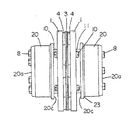
図1乃至図4において軸継手の軸締結装置を説明する。板バネ式軸継手を示すもので、1は軸を挿入締結するテーパーボス部2を一体形成した一対の円型金属製等フランジ部で、両フランジ部間に複数枚の四角形の板バネ3、座金4を介在してボルト5を一方のフランジ部の周面の円孔12より座金4、板ばね3、座金4を挿通して他方のフランジ部の周囲の螺孔13に螺合して締付けて連結したものである。
【0012】
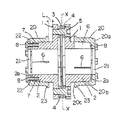
図3、図5および図6において、この発明は前記軸継手の軸締結手段として、両側のフランジ部1のテーパーボス部2にその周面の三等分した位置にボス部2の基端近くまで軸方向に割り溝6が形成され、かつ三等分したボス部端面2aにはテーパーキャップ20の端面20aのボルト挿通孔22と合致する位置に螺孔7が等分に配設されて構成されている。実施形態では螺孔7は前記テーパーキャップの挿通孔22と合わせ、ボス部2の三分割した各分割片に2個ずつ一定の間隔をおいて設けられている。而して、テーパーキャップ20をテーパーボス部2に被せ、テーパーキャップの挿通孔22を通じて締付けボルト8をボス部の端面2aの螺孔7に締付けることにより3等分に分割した分割片が中心に向かって均等に縮径され均等に軸締結することができる。なお、螺孔7の数は2個に限られるものではなく、一個、3個等均等な間隔に配置することができる。
【0013】
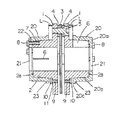
図1、図5、図6において、この発明は前記軸継手の軸締結解除手段として、フランジ部1の側面と締結時のテーパーキャップ20の先端面との間の間隔Lは少なくとも締結解除用ボルト10をセットできる間隔をあける。実施形態ではボルト10の頭部10a、座金11の厚みより若干広い間隔Lとするように設けられている。また、フランジ部の側面には、テーパーキャップ20に対抗する位置に複数の締結解除ボルト用螺孔9が設けられ、該螺孔9に締結解除用ボルト10が螺挿されてセットされて構成されている。実施形態ではテーパーキャップ20をこじることなく押し上げるために、フランジ部1の周面の4箇所に等間隔に螺孔9が設けられてボルト10が螺挿されている。ハブの長さは短くし、螺孔9の径を小径として、テーパーボス部の縮径に影響なく、また、その螺孔9を設ける位置はボス部の割り溝6の位置より離れた位置に設け、応力の影響を生じないようにするのが好ましい。締結解除用ボルト10はスパナ等工具で緩めるときのトルクによりテーパーキャップを押す押圧力がかかるので、その押圧に充分な最小の径であればよく、またその長さはフランジ部の螺孔と間隔Lの合計より長くする。かつまた、締結解除用ボルトは解除専用であるからビス程度の小径でよいので、慣性が大きくなることがなく、動バランスがくずれることがない。螺孔から締結解除用ボルト10が外されないので、紛失の恐れもなく、保守に便利である。なお、螺孔9を設ける箇所はテーパーキャップに対抗する周面の4箇所か3箇所が好ましい。
【0014】
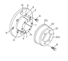
図3乃至図6において、テーパーキャップ20は、前面中央に軸孔21を有する内径の金属製等の筒状キャップで、内周に前記テーパーボス部2に嵌合させるテーパー面20bが形成され、キャップ20の端面20aには外周にボス部の螺孔に合致する位置に複数の挿通孔22が形成されている。実施形態ではボス部の螺孔に対応して6個の挿通孔22が形成されている。また、テーパーキャップ20の開口周囲の先端面20cは外周に鍔部23を設けて幅を広くして、前記締結解除用ボルトの頭部10aが的確に当接するようにしてある。テーパーキャップ20のフランジ側先端面20cとボルト10の頭部はともに平面としてぴったりと当接可能とする。前記キャップ20は肉厚が薄いので、キャップ20の端面20aの内面が傾斜状として厚肉としてあり、それに対応してボス部2の端面も傾斜面としてある。
【0015】
上記したこの発明の構造によれば、軸締結の場合について説明すると、予めフランジ部1の側面の螺孔9に締結解除用ボルトを螺挿してセットし、このフランジ部1のボス部2にテーパーキャップ20を被せて駆動軸或いは被動軸等の軸を軸孔21とボス部2の内径に挿入し、テーパーキャップ20の端面の挿通孔22を通じてボス部端面2aの螺孔7に締付けボルト8をねじ込み、テーパーキャップ20のテーパー面20bを押して三分割としたボス部2を均等に縮径して軸に締結できる。この軸締結において三分割したボス部には各分割片に均一の縮径力がかかるのでそれにつながるフランジ部にも均等の内部応力がつたわるが、フランジ部に変形する影響を与えることはない。
【0016】
軸締結を解除する場合には、テーパーキャップ20の締付けボルト8を緩め、予めセットした締結解除用ボルト10をスパナ等の工具で緩める方向に回してトルクによりテーパーキャップ20の先端面20cを押してテーパーキャップ20をテーパーボス部2より離してボス部による縮径を解除し、軸締結を解除することができる。フランジ部の基部に締結解除ボルト用螺孔9を設けるも等間隔に設けられ、かつそのボルトの径が小径でよいので、フランジ部にかかる応力により変形を生ずることはない。
従って、工作機械、ロボット、OA機器等において制御用モートルの高精度、位置決め等に利用すれば、軸とボス部との位置関係を変更する場合、或いは軸をボス部より取り外す場合に軸締結の分離作業を速やかに行うことができる。
上記の軸締結と軸締結解除により、位相をずらす際の軸継手の点検、調整が簡単にできる。
【0017】
以上の実施形態を示したが、この発明はこの形態に限定されるものではなく、この発明の要旨を逸脱しない範囲で、様々な形態を実施しうるものである。実施形態では、テーパーキャップを使用した場合で説明したが、この構造に限られるものではなく、テーパー環状部材等テーパーを利用してボス部に嵌合締結できる構造のものであればよい。又、軸締結装置は上記のものに限られるものではなく、例えば、両側のフランジ部の対向面にクロスに備えた軸受けアームをクロスジョイントピンで結合し、フランジ部のボス部にテーパー加圧部材を嵌合し前記と同様に締結手段で締結して二軸間の伝達を行う軸継手、カップリング等でもよい。
【0018】
【発明の効果】
この発明によれば、フランジ部に設けたテーパーボス部を三分割し、テーパーボス部の端面にはテーパーキャップ端面のボルト挿通孔の孔とピッチが均等になるように螺孔を設けたので、テーパーボス部にテーパーキャップを締付け手段で締付け時、ボス部の各分割片を軸に対して均等に縮径して軸締結することができる。ボス部を三分割したことによりテーパーキャップによる締付け時に三等分した分割片に均等の縮径力がかかり、各分割片が中心に向かって均等に縮径されるので応力均一にかつ強固に軸締結ができる。而して、この軸締結手段によれば、テーパーボス部の変形、フランジ部の変形、芯ぶれ等がなく、機械の芯だしが簡単にできる。従って、工作機械、ロボット、OA機器等において制御用モートルの高精度、位置決め等に利用する軸継手のボス部をテーパーキャップで均等に締結できる。
【0019】
この発明によれば、テーパーキャップの先端面に対抗するフランジ部の側面側に締結解除用ボルトをセットしたので、軸締結を解除する場合には、テーパーキャップの頭部の締付けボルトを緩めてから、フランジ部にセットした締結解除用ボルトをスパナ等工具により緩めてそのトルクによりテーパーキャップの先端面を僅かに押し上げるだけで、テーパキャップを簡単にボス部より離れさせて軸締結を解除することができる。締結解除用ボルトは解除専用であるからビス程度の小径でよいので、慣性が大きくなることがなく、動バランスがくずれることがない。螺孔から締結解除用ボルトが外されないので、紛失の恐れもなく、保守に便利である。従って、工作機械、ロボット、OA機器等において制御用モートルの高精度、位置決め等に利用すれば、軸とボス部との位置関係を変更する場合、或いは軸をボス部より取り外す場合に軸締結の分離作業を速やかに行うことができて便利である。又、テーパーキャップを緩めるだけで位相の変位等を調整して軸締結できるので、軸締結装置とモートル、機械等間の間隔を狭くでき、軸締結装置の軸の長さが長くなることなく、機械の性能に影響なく、振動、捩じれが生ずることもない。
【図面の簡単な説明】
【図1】この発明の軸締結装置を示す正面図である。
【図2】同一部破断側面図である。
【図3】同縦断面図である。
【図4】図3のX−X線における断面図である。
【図5】図2におけるY−Y線断面図である。
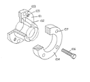
【図6】フランジ部とテーパーキャップを分離して示す斜視図である。
【図7】従来の軸締結装置を示す正面図である。
【図8】同縦断面図である。
【図9】フランジ部とリングを分離して示す斜視図である。
【符号の説明】
1 フランジ部
2 テーパーボス部
6 割り溝
7 螺孔
8 締付けボルト
9 締結解除ボルト用螺孔
10 締結解除用ボルト
20 テーパーキャップ
20c 先端面
21 軸孔
22 挿通孔[0001]
BACKGROUND OF THE INVENTION
In the present invention, a boss portion of a shaft joint used for high accuracy and positioning of a control motor in machine tools, robots, office automation equipment, etc. can be evenly fastened with a taper cap, and the fastened taper cap is loosened with a shaft fastening release means. The present invention relates to a shaft fastening device for a shaft coupling that releases shaft fastening.
[0002]
[Prior art]
Conventionally, in this type of shaft coupling shaft fastening device, as shown in FIGS. 7 to 9, a
[0003]
[Problems to be solved by the invention]
In the conventional shaft joint, when the
[0004]
In order to solve the above-described conventional problems, the inventor divides the tapered boss into three equal parts, and also provides bolt insertion holes on the end face of the taper cap, and tightens the boss part and the taper cap. An object of the present invention is to provide a shaft fastening device for a shaft coupling that can reduce the runout of the outer periphery and side surfaces of the flange portion by equalizing the diameter reduction of the boss portion at the time of fastening by means and making the stress balance in the circumferential direction uniform.
[0005]
As another object, the shaft coupling shaft can be easily and evenly released by loosening the taper cap fastened using the torque of the bolt of the shaft fastening release means provided in advance in the flange boss. It is to provide a fastening device.
[0006]
[Means for solving the problems]
A shaft fastening device for a shaft joint according to a first aspect of the present invention is a shaft joint for fastening a shaft by fastening a
[0007]
According to the configuration of the first invention described above, the
[0008]
Jikushime YuiSo location of the shaft coupling of the invention of
[0009]
According to the second invention, since the
[0010]
DETAILED DESCRIPTION OF THE INVENTION
An embodiment of the present invention will be described with reference to the drawings. 1 is a front view showing a shaft fastening device of the present invention, FIG. 2 is a cutaway side view of the same part, FIG. 3 is a longitudinal sectional view thereof, FIG. 4 is a sectional view taken along line XX of FIG. 6 is a perspective view showing the flange portion and the taper cap separately, FIG. 7 is a front view showing a conventional shaft fastening device, FIG. 8 is a longitudinal sectional view, and FIG. 9 is a flange portion. FIG.
[0011]
A shaft fastening device for a shaft coupling will be described with reference to FIGS. A leaf spring type shaft joint is shown. 1 is a pair of circular metal equal flange portions integrally formed with a
[0012]
3, 5, and 6, the present invention is used as a shaft fastening means of the shaft coupling in the vicinity of the base end of the
[0013]
In FIGS. 1, 5, and 6, the present invention is a shaft fastening release means for the shaft coupling, and the distance L between the side surface of the flange portion 1 and the tip surface of the
[0014]
3 to 6, the
[0015]
According to the above-described structure of the present invention, the case of shaft fastening will be described. A fastening release bolt is inserted into the
[0016]
When releasing the shaft fastening, the
Therefore, if it is used for high accuracy and positioning of the control motor in machine tools, robots, OA equipment, etc., the shaft fastening is performed when the positional relationship between the shaft and the boss portion is changed or when the shaft is removed from the boss portion. Separation work can be performed promptly.
By the above-described shaft fastening and shaft fastening release, it is possible to easily check and adjust the shaft joint when shifting the phase.
[0017]
Although the above embodiment was shown, this invention is not limited to this form, Various forms can be implemented in the range which does not deviate from the summary of this invention. In the embodiment, the case where the taper cap is used has been described. However, the present invention is not limited to this structure, and any structure that can be fitted and fastened to the boss portion using a taper such as a tapered annular member may be used. Further, the shaft fastening device is not limited to the above-mentioned one. For example, a bearing arm provided in a cross is coupled to the opposing surfaces of the flange portions on both sides by a cross joint pin, and a taper pressure member is attached to the boss portion of the flange portion. A shaft coupling, a coupling, or the like that engages and fastens with the fastening means in the same manner as described above and transmits between the two shafts may be used.
[0018]
【The invention's effect】
According to this inventions, the tapered boss portion provided in the flange portion divided into three parts, since the end faces of the tapered boss provided screw holes as the hole pitch of the bolt insertion hole of the tapered cap end face is equalized When the taper cap is tightened to the taper boss portion with the tightening means, each of the divided pieces of the boss portion can be evenly reduced in diameter with respect to the shaft and fastened to the shaft. Boss takes three divided evenly shrinkage径力the split piece was divided into three equal during tightening by the tapered cap by a, the stress evenly and firmly respective segments are reduced in diameter uniformly toward the center The shaft can be fastened. Thus, according to this shaft fastening means, there is no deformation of the taper boss portion, deformation of the flange portion, runout, etc., and the centering of the machine can be easily performed. Accordingly, the boss portion of the shaft coupling used for high accuracy and positioning of the control motor in machine tools, robots, OA equipment, etc. can be evenly fastened with the taper cap.
[0019]
According to the present invention, since the fastening release bolt is set on the side surface of the flange portion opposed to the tip surface of the taper cap, when releasing the shaft fastening, after loosening the fastening bolt on the head portion of the taper cap. By simply loosening the fastening release bolt set on the flange with a tool such as a spanner and slightly pushing up the tip of the taper cap with its torque, the taper cap can be easily separated from the boss to release the shaft fastening. it can. Since the fastening release bolt is exclusively used for release, it can be as small as a screw, so inertia does not increase and dynamic balance is not lost. Since the fastening release bolt is not removed from the screw hole, there is no risk of losing and it is convenient for maintenance. Therefore, if it is used for high accuracy and positioning of the control motor in machine tools, robots, OA equipment, etc., the shaft fastening is performed when the positional relationship between the shaft and the boss portion is changed or when the shaft is removed from the boss portion. The separation work can be performed quickly and is convenient. In addition, since the shaft can be fastened by adjusting the phase displacement, etc., simply by loosening the taper cap, the distance between the shaft fastening device and the motor, machine, etc. can be narrowed, without increasing the length of the shaft of the shaft fastening device. There is no effect on machine performance, and no vibration or twisting occurs.
[Brief description of the drawings]
FIG. 1 is a front view showing a shaft fastening device of the present invention.
FIG. 2 is a side sectional view of the same part.
FIG. 3 is a longitudinal sectional view of the same.
4 is a cross-sectional view taken along line XX of FIG.
FIG. 5 is a cross-sectional view taken along line YY in FIG.
FIG. 6 is a perspective view showing a flange portion and a taper cap separately.
FIG. 7 is a front view showing a conventional shaft fastening device.
FIG. 8 is a longitudinal sectional view of the same.
FIG. 9 is a perspective view showing a flange portion and a ring separately.
[Explanation of symbols]
DESCRIPTION OF SYMBOLS 1
Claims (2)
前記テーパーキャップの端面に締付け手段の締付けボルトを挿通するボルト挿通孔を等分に設け、
前記テーパーボス部の周面を三等分した位置にボス部の基端近くまで割り溝を形成するとともに三等分したボス部端面には前記テーパーキャップ端面に設けたボルト挿通孔と合致する位置に螺孔を配設し、
テーパーキャップを三分割したボス部に締付けボルトで締付けてボス部を均等に縮径して軸締結しうることを特徴とする軸継手の軸締結装置。In the shaft joint that tightens the taper cap by tightening the taper cap to the taper boss part formed integrally with the flange part,
Bolt insertion holes for inserting the tightening bolts of the tightening means are equally provided on the end face of the taper cap,
A position where the peripheral surface of the tapered boss part is divided into three equal parts and a split groove is formed close to the proximal end of the boss part, and the boss part end face divided into three parts is a position that matches the bolt insertion hole provided in the end face of the taper cap Screw holes,
A shaft fastening device for a shaft coupling, wherein the taper cap can be fastened with a fastening bolt to a boss portion obtained by dividing the taper cap into three parts and the boss portion can be uniformly reduced in diameter to be fastened.
前記フランジ部側面とボス部に締付け手段で締付けるテーパーキャップの先端端面との間に締結解除ボルトの頭部より広い間隔を存し、テーパーキャップの先端面に対抗するフランジ部側面側に締結解除ボルト用螺孔を設け、該螺孔に締結解除ボルトを螺挿してセットしたことを特徴とする軸継手の軸締結装置。In the shaft joint that fastens the taper cap by fastening means to the taper boss part formed integrally with the flange part with the fastening means,
A fastening clearance bolt is provided on the side of the flange portion that faces the front end surface of the taper cap, with a gap wider than the head of the fastening release bolt between the side surface of the flange portion and the tip end surface of the taper cap that is tightened to the boss portion by tightening means. A shaft fastening device for a shaft coupling, wherein a screw hole is provided and a fastening release bolt is screwed into the screw hole.
Priority Applications (1)
| Application Number | Priority Date | Filing Date | Title |
|---|---|---|---|
| JP37533298A JP3834159B2 (en) | 1998-12-14 | 1998-12-14 | Shaft fastening device for shaft coupling |
Applications Claiming Priority (1)
| Application Number | Priority Date | Filing Date | Title |
|---|---|---|---|
| JP37533298A JP3834159B2 (en) | 1998-12-14 | 1998-12-14 | Shaft fastening device for shaft coupling |
Publications (3)
| Publication Number | Publication Date |
|---|---|
| JP2000179563A JP2000179563A (en) | 2000-06-27 |
| JP2000179563A5 JP2000179563A5 (en) | 2004-11-04 |
| JP3834159B2 true JP3834159B2 (en) | 2006-10-18 |
Family
ID=18505350
Family Applications (1)
| Application Number | Title | Priority Date | Filing Date |
|---|---|---|---|
| JP37533298A Expired - Fee Related JP3834159B2 (en) | 1998-12-14 | 1998-12-14 | Shaft fastening device for shaft coupling |
Country Status (1)
| Country | Link |
|---|---|
| JP (1) | JP3834159B2 (en) |
Families Citing this family (7)
| Publication number | Priority date | Publication date | Assignee | Title |
|---|---|---|---|---|
| JP4862880B2 (en) * | 2008-11-21 | 2012-01-25 | 株式会社島津製作所 | Structure testing machine |
| JP2010181298A (en) * | 2009-02-06 | 2010-08-19 | Japan Aviation Electronics Industry Ltd | Servo type accelerometer |
| WO2011048186A1 (en) * | 2009-10-21 | 2011-04-28 | Zero-Max Holding Dk A/S | Torque limiting assembly |
| EP2314893A1 (en) * | 2009-10-21 | 2011-04-27 | Zero-Max Holding Dk A/S | Torque limiting assembly |
| JP5483611B2 (en) * | 2011-03-29 | 2014-05-07 | 株式会社ツバキE&M | Shaft coupling release structure |
| JP2015232292A (en) * | 2014-06-10 | 2015-12-24 | 株式会社日立製作所 | Wind power generation device |
| CN109555722A (en) * | 2018-12-14 | 2019-04-02 | 上海凯泉泵业(集团)有限公司 | A kind of vertical long shaft pump of point of half formula Axile connection structure and bush of bush bearing one |
Family Cites Families (8)
| Publication number | Priority date | Publication date | Assignee | Title |
|---|---|---|---|---|
| JPS5896023U (en) * | 1981-12-23 | 1983-06-29 | マツダ株式会社 | Engine timing chamber cover structure |
| JPS6117718A (en) * | 1984-07-05 | 1986-01-25 | Masanori Mochizuki | Universal joint |
| JPS62131121U (en) * | 1986-02-13 | 1987-08-19 | ||
| JPS643330A (en) * | 1987-02-24 | 1989-01-09 | Tsubakimoto Chain Co | Fastener for shaft and rotor |
| JPH01288622A (en) * | 1988-05-12 | 1989-11-20 | Fuji Xerox Co Ltd | Shaft coupling |
| JPH0297716A (en) * | 1988-10-05 | 1990-04-10 | Masaharu Kubokawa | Shaft coupling |
| JPH05306720A (en) * | 1992-05-06 | 1993-11-19 | Katayama Chain Kk | Rotary shaft installation structure of revolution transmission member |
| JPH10238519A (en) * | 1997-02-25 | 1998-09-08 | Miki Puurii Kk | Friction fastening device |
-
1998
- 1998-12-14 JP JP37533298A patent/JP3834159B2/en not_active Expired - Fee Related
Also Published As
| Publication number | Publication date |
|---|---|
| JP2000179563A (en) | 2000-06-27 |
Similar Documents
| Publication | Publication Date | Title |
|---|---|---|
| US3463520A (en) | Combination collar-clamp and shaft coupling | |
| US6190102B1 (en) | Studs for connecting a wheel and a brake element to a motor vehicle wheel hub unit | |
| US5209594A (en) | Arrangement for locking a shaft to a machine member | |
| GB2131916A (en) | A self-centering torque transmission assembly | |
| JP3834159B2 (en) | Shaft fastening device for shaft coupling | |
| US20030063949A1 (en) | Expandable key for interconnecting a shaft and hub | |
| JP2516283Y2 (en) | Fastening device for shaft and rotating body | |
| JPH0579846B2 (en) | ||
| US4425816A (en) | Structure for securing a cylinder drive gear to the end of a cylinder shaft in a printing machine | |
| US3972635A (en) | Double conical hub-to-shaft connection | |
| KR20050011676A (en) | Fastening apparatus of shaft with rotative body | |
| GB2069660A (en) | Device for securing a cylinder drive gear to a shaft | |
| US5613795A (en) | Conical connecting device for connecting machine components | |
| US5067220A (en) | Front wheel drive hub puller | |
| JP2000179563A5 (en) | ||
| JPH075294Y2 (en) | Lock nut | |
| JPS6245041Y2 (en) | ||
| KR200205987Y1 (en) | Rod wire disk roll | |
| JPH08114213A (en) | Screw part with wedge | |
| JPS6114749Y2 (en) | ||
| JPH0842582A (en) | Fastening mechanism for shaft | |
| JP2895029B2 (en) | Forging and forging tools | |
| JPH0217849A (en) | Structure for stopping rotation of rotor of generator of engine | |
| JPH10281171A (en) | Friction type rigid shaft coupling | |
| JP3755985B2 (en) | Shaft fastener |
Legal Events
| Date | Code | Title | Description |
|---|---|---|---|
| TRDD | Decision of grant or rejection written | ||
| A01 | Written decision to grant a patent or to grant a registration (utility model) |
Free format text: JAPANESE INTERMEDIATE CODE: A01 Effective date: 20060711 |
|
| A977 | Report on retrieval |
Free format text: JAPANESE INTERMEDIATE CODE: A971007 Effective date: 20060714 |
|
| A61 | First payment of annual fees (during grant procedure) |
Free format text: JAPANESE INTERMEDIATE CODE: A61 Effective date: 20060721 |
|
| R150 | Certificate of patent or registration of utility model |
Free format text: JAPANESE INTERMEDIATE CODE: R150 |
|
| FPAY | Renewal fee payment (event date is renewal date of database) |
Free format text: PAYMENT UNTIL: 20090728 Year of fee payment: 3 |
|
| FPAY | Renewal fee payment (event date is renewal date of database) |
Free format text: PAYMENT UNTIL: 20120728 Year of fee payment: 6 |
|
| FPAY | Renewal fee payment (event date is renewal date of database) |
Free format text: PAYMENT UNTIL: 20120728 Year of fee payment: 6 |
|
| FPAY | Renewal fee payment (event date is renewal date of database) |
Free format text: PAYMENT UNTIL: 20150728 Year of fee payment: 9 |
|
| LAPS | Cancellation because of no payment of annual fees |