JP3832684B2 - Watering nozzle for fire extinguishing of fixed fire extinguishing equipment - Google Patents
Watering nozzle for fire extinguishing of fixed fire extinguishing equipment Download PDFInfo
- Publication number
- JP3832684B2 JP3832684B2 JP17360197A JP17360197A JP3832684B2 JP 3832684 B2 JP3832684 B2 JP 3832684B2 JP 17360197 A JP17360197 A JP 17360197A JP 17360197 A JP17360197 A JP 17360197A JP 3832684 B2 JP3832684 B2 JP 3832684B2
- Authority
- JP
- Japan
- Prior art keywords
- nozzle
- water
- fire
- fire extinguishing
- slit
- Prior art date
- Legal status (The legal status is an assumption and is not a legal conclusion. Google has not performed a legal analysis and makes no representation as to the accuracy of the status listed.)
- Expired - Fee Related
Links
Images


Description
【0001】
【発明の属する技術分野】
本発明は、スプリンクラー消火設備などの固定式消火設備に使用される固定式消火設備の消火用散水ノズルに関する。
【0002】
【従来の技術】
従来、この種のスプリンクラー消火設備に使用される消火用散水ノズルとしては、防護範囲全体に均一に散水させるため、水をデフレクタで分散させて粒状態に散水しており、例えば図11に示すようなものがある(特開平5−69730号)。
【0003】
図11はヒュージブルリンク式の消火用散水ノズルを示し、ノズル本体101に放水口102が形成され、放水口102に設けた栓103とデフレクタ104との間に一対のレバー105a,105bを接触点106a,106b,106cによって係止し、栓103を閉鎖状態に支持している。レバー105aとレバー105bには感熱体としてのヒューズ107で固着された一対のリンク108a,108bが装着され、栓103の閉鎖状態を維持している。
【0004】
火災の発生による温度上昇でヒューズ107が溶けると、一対のリンク108a,108bが矢印で示すように分解し、レバー105a,105bの係止が解除され、水圧によってレバー105a,105bが弾け、放水口102から栓103が脱落して加圧水が放水口102から噴出し、散水が開始される。このとき放水口102から噴出した水は、デフレクタ104に当って防護範囲全体に均一に散水される。
【0005】
【発明が解決しようとする課題】
しかしながら、このような従来の消火用散水ノズルにあっては、1個のノズル当り例えば80リットル/分以上という所定流量の連続放射となっていたため、火災消火能力に対して比較的多くの消火液あるいは水の量が必要であり、当然消火する対象物以外のものにも放射されるため、放射した消火液あるいは水による二次災害、いわゆる水損が大きくなるという問題点があった。また設備的には、水槽、ポンプが大容量となる上、配管サイズも大きくなり、設備全体の費用が高くなるという問題点もあった。
【0006】
また従来の散水ノズルでは、防護範囲全体に均一に散水させるため、水をデフレクタで分散させて粒状にして散水している。そのため、火災の勢いが強い場合には、分散された水は粒子径が小さいため、火災の気流に負けて火災の深部に達する前に蒸発し、火災の抑制に時間がかかり、また全く消火できないこともある。このため水の量も多くなり、水損による被害も大きくなる。
【0007】
更に、防護範囲内のある一点から見ると、粒状の水により、一瞬その一点の火災の炎が弱まったとしても、その地点の付近の炎により一度かかった水が蒸発し、付近の炎によって再び燃え始める。このため完全に消火するまでに時間がかかる。
本発明は、このような問題点に鑑みてなされたものであって、火災消火能力を確保しながら、消火用散水ノズル1個あたりの放射量を低減することで水損を少なくし、水槽、ポンプなどの容量を小容量とし設置費用を低減することができる固定式消火設備の消火用散水ノズルを提供することを目的とする。
【0008】
また本発明は、スリットから放出された水の均一な散布パターンが得られるノズル構造を備えた消火用散水ノズルを提供することを目的とする。
【0009】
【課題を解決するための手段】
この目的を達成するために、本発明は次のように構成する。
本発明は、消火液または消火用水が圧送される消火用配管に接続され火災時に消火液または消火用水を散水する固定式消火設備の消火用散水ノズルを対象とする。
【0010】
このような消火用散水ノズルとしては、本発明にあっては、所定の防護範囲内の特定部分に集中的に散水する散布パターンを形成するスリットを備えた旋回自在なノズル部と、ノズル部から消火液又は消火用水を散水する際の水流を駆動源として駆動軸を回転させる駆動部と、駆動部の回転を入力し所定の減速比に従って減速してノズル部を回転させ散布パターンを所定の防護範囲内を走査して所定の防護範囲内全域に散水させる減速部と、消火液又は消火用水を散水する際の水流を駆動源としてノズル部の内部で回転される羽根車とを備えたことを特徴とする。
【0011】
このような構成を備えた本発明の消火用散水ノズルによれば、防護範囲内にある部分を集中的に散水するように散布パターンを形成し、防護範囲内を走査するようにしたので、火災に対して瞬間的には従来の散水ノズルより大量の消火液が放射されるため、従来の80リットル/分の防護範囲全域放射の散水ノズルと例えば40リットル/分の回転走査で1rpm程度の場合と比較すると、防護範囲内全体でみて少ない水量にもかかわらず、より高い消火能力が得られる。
【0012】
また、本発明は、瞬時的には散水量が増えると同時に、消火対象物にあたる水の打力及び粒子径も増すので、消火能力が増加する。即ち、本発明においては、水は分散された粒状ではなく、特定の部分に集中的に散水される打力の強い水の塊として消火対象物に散水されるため、火災気流に負けることなく火災の深部まで到達して消火能力が高くなり、火災抑制までの時間が短くて済み、従って鎮火までの水量も少なくて済む。また塊状態の水で消火するため、一度消火した部分が再び燃え上がることを抑制し、一度消火された場所を継続して鎮火状態にできる。
【0013】
また、少ない放射量で消火できるため、いわゆる水損の被害を小さくすることができる。更に、放射水の水槽が小さくなり、ポンプが小容量となり、自家発電設備等バックアップ設備も小容量となり、配管サイズも小さくなるため、低コストとなる。
また、防護範囲を従来の散水ノズルと比較して大きくした場合でも、走査時間を調整することにより、火災に対しては瞬間的には大量の水を放射することができ、同等以上の消火性能が得られることから、従来の散水ノズルと比較して、ノズルの設置個数を減らすことができる。
【0014】
更に、スリットを開口したノズル部の内部に、スリット方向に対し略直交する方向に複数の羽根を備えノズル部の水流を駆動源として回転される羽根車を設けたことで、理想的な散布パターンが得られる。即ち、スリットのみの場合には、スリットから出た水は互いに集まるように落ち、散布量が均一化された理想的な散布パターンとならない。しかし、回転する羽根車の羽根によって水を1つ1つの固りに区切ってスリットから出すことによって、スリットから出た水が集まって落ちることが抑えられ、理想的な散布パターンが得られる。
【0015】
本発明の消火用散水ノズルにあっては、ノズル部のスリットとして防護範囲内の遠隔部に散水するスリット箇所ほどスリット幅を広く設定する。
また本発明の消火用散水ノズルは閉鎖型であり、ノズル部は内部の流入路を開閉する弁体を連結し、火災により所定温度に達したら脱落する感熱作動機構により弁体を定常監視状態で流入路を閉鎖する位置に保持しており、感熱作動機構が分解した際に下降してノズル部先端を露出すると共に弁体により流入路を開いて消火液又は消火用水を流す。
【0016】
この閉鎖型の消火用散水ノズルにつき、弁体により定常監視状態で閉鎖された流入路の一次側に第1ストレーナを設けると共に、二次側に第2ストレーナを設け、消火液又は消火用水に混入しているゴミ等の異物による流路のつまりを防止する。ここで消火液又は消火用水が充満している弁体1次側に設置する第1ストレーナの網目を、大気に開放状態にある弁体2次側に設置した第2ストレーナの網目よりも粗くしている。
【0017】
これはストレーナに使用している網目が細かいほど錆やすいという性質に着目したもので、消火液又は消火用水が入っている弁体1次側に設置する第1ストレーナの網目を粗くして錆にくくする。第1ストレーナの網目を粗くしていても、大気開放側に目の細かい第2ストレーナがあるので、ゴミ等の異物は確実に除去できる。
【0018】
感熱作動機構で弁体を開閉する閉鎖型の消火用散水ノズルとした場合、ノズル本体に対し流入路側から駆動部、減速部、及び羽根車を内蔵したノズル部を順に配置し、駆動部に対しノズル部を軸方向に摺動自在で軸回りに一体回転するスライド連結部を介して連結し、感熱作動機構の分解時にノズル部をスライドさせた状態で駆動部の回転をノズル部に伝達する。
【0019】
【発明の実施の形態】
図1は本発明による固定式消火設備の消火用散水ノズルの外観説明図である。本発明の消火用散水ノズル1は円筒状のノズル本体2を有し、ノズル本体2の上部に消火ポンプ設備から加圧された消火液または消火用水が供給される消火配管に接続する接続ネジ部3を有し、ノズル本体2の下部に火災により所定温度に達した時に脱落する感熱作動機構4を設けている。
【0020】
図2は図1の内部構造の断面図であり、中心線の左側にノズル本体2のケースを破断した内部構造を示し、右半分に内部構造の断面を示している。
図2において、ノズル本体2は接続ネジ部3が設けられた上方側よりケース2a,2b,2c及び2dの4つをねじ込みにより軸方向に連結している。上部のケース2aに一体に設けられた接続ネジ部3の内部には流入路5が軸方向に形成され、ノズル本体2の中央に配置した軸12の先端に一体に形成した弁体11を弁座11aに収納して、流入路5を定常監視状態で閉鎖している。
【0021】
このため流入路5は、一次側流入路5aと二次側流入路5bに弁体11による流入路5の閉鎖で分けられている。弁体11の閉鎖で分けられた一次側流入路5a側には第1ストレーナ13が設置され、一方、二次側流入路5bには第2ストレーナ14が設けられている。
第1ストレーナ13及び第2ストレーナ14は共に加圧供給される消火液や消火用水に混入しているゴミなどの異物を除くためのものであり、弁体11で閉じられた一次側流入路5aには定常監視状態で消火液または消火用水が加圧状態で充満しており、その中に第1ストレーナ13が設置されている。これに対し第2ストレーナ14は、弁体11で閉鎖された流入路5の二次側流入路5bにあることから、大気に開放された状態にある。
【0022】
一般に網目構造をもつストレーナは、網目が小さいほど水に浸していた場合の腐食の度合いが大きいことが知られている。そこで本発明にあっては、消火液や消火用水に浸されている一次側流入路5a側の第1ストレーナ13の網目を大きくして腐食しにくくし、一方、大気側に開放された状態で設置されている第2ストレーナ14については細かい網目のものを使用している。これによって一次側流入路5a側に設置した第1ストレーナ13を腐食しにくくし、耐久性を高めている。
【0023】
第1ストレーナ13及び第2ストレーナ14を設置した流入路5に続いては駆動部6が設けられる。駆動部6は、円筒状のケーシング6bの外周に複数枚のインペラ6aを配置した水車構造であり、ケーシング6bはケース2bの内部に一体に形成したハウジング16に装着したベアリング17を介して回転自在に指示さている。このため消火液または消火用水を散水する際に上から下に流れる水流をインペラ6aで受けてケーシング6bが回転駆動される。
【0024】
駆動部6の内部には減速部7が組み込まれている。ハウジング15はケース2bの内部に一体に形成したハウジング16にネジ込み固定しており、ハウジング15の中心軸方向には弁体11を備えた軸12が摺動自在に嵌め込まれている。またハウジング16の上側には軸12が下降して弁体11が弁座11aから離れて開いた時に収納する弁体収納部16aが形成されている。
【0025】
減速部7として、この実施形態にあっては、ダブル遊星歯車機構を使用している。即ちハウジング16にネジ込み固定されたハウジング15にサンギア18aを固定し、サンギア18aの外側にプラネタリギア19を介してインターナルギア21を配置し、インターナルギア21は駆動部6のケーシング6bの内側に固定されている。
【0026】
プラネタリギア19はキャリアケース20に回転自在に装着されている。続いてサンギア18bが上部のサンギア18aと同様、軸12側のハウジング15に固定され、サンギア18bに対しプラネタリギア22を介してキャリアケース20に固定されたインターナルギア23を噛み合わせている。プラネタリギア22は回転出力部材としてのキャリアケース24に回転自在に装着されている。
【0027】
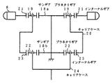
この減速部7のダブル遊星歯車機構は、図3に取り出して示すようなギア配列をもっている。このようなダブル遊星歯車機構により、例えば水流による駆動部6のインペラ6aの水流回転を例えば1000分の1以下の高減速比で減速してキャリアケース24の回転として取り出すことができる。
再び図2を参照するに、ハウジング6b上部の外周面とハウジング16の内周面との隙間、およびハウジング6b、下部の内周面とキャリアケース24の外周面との隙間は、極力狭く設計されている。これは、消火用水中のゴミが上記隙間から減速部7内に入ってギア機構にゴミづまりが起き、減速部7が動作しなくなることを防止している。そのため、減速部7は、駆動部6の中にほぼ被包した状態で収納されている。
【0028】
減速部7に続いてはノズル部8が設けられている。ノズル部8の上部は、減速部7のキャリアケース24から軸方向に延在した固定ガイド25に対し、スライダ連結部26により軸方向に褶動自在で且つ軸回りに連結するように装着されている。即ち、ノズル部8のスライダ連結部26は、キャリアケース24から延在した固定ガイド25に対し褶動自在なスライダ27を例えば円周方向の4箇所に配置しており、4本のスライダ27をフランジ28の周囲に一体に形成した支持しており、フランジ28はネジ35によりリテーナ34を介して軸12の先端に固定されている。またリテーナ34と上部に位置する減速部7側のストッパ部材29との間にはスプリング30が組み込まれ、ノズル部8側を下方に押圧している。
【0029】
スライダ連結部26の構造は図2のA−A断面を示す図4から明らかになる。図4において、ノズル部8側のスライダ連結部26は、中央のフランジ28の周囲4箇所に配置されたスライダ27で構成され、スライダ27はフランジ28に対し図2のように軸方向に延在している。
このようなノズル部8側のスライダ連結部26に対し、上側に位置する減速部7の回転出力部材となるキャリアケース24より延在している固定ガイド25が、4箇所に形成したスライダ27の間2箇所に位置している。このため減速部7側の固定ガイド25に対しノズル部8側のスライダ27は、軸方向に移動可能であるが軸回りには固定ガイド25と連結関係にあり、固定ガイド25側からの回転を受けてスライダ27はフランジ28と共に一体に回転される。
【0030】
再び図2を参照するに、ノズル部8の上部にはガイドプレート31がねじ止め固定されている。ガイドプレート31の内側は、図4の想像線で示すように、内周部31aを固定ガイド25の外周とノズル部8の内周の間の空間に位置しており、且つスライダ27同士の間に固定ガイド25がない2箇所の部分においては中央側に伸びており、スライダ27に内周部31aが引掛るようになっている。このため、スライダ27に対しガイドプレート31は軸方向に褶動自在で且つ軸回りには一体に回転するスライダ連結部を構成している。
【0031】
再び図2を参照するに、ガイドプレート31とノズル部8の上端との間には、ねじ止めの際にシート32が挟み込み固定されている。シート32は、ケース2cの内周まで延在したサイズを持っている。このシート32は、感熱作動部4が火災により所定温度に達して脱落した際に、ノズル部8と共に下降してシート圧着段部33に圧着され、外側のケースとノズル部8の間を通る水の漏れ出しを阻止するバルブシートとして機能する。
【0032】
ノズル部8の先端の球状部には、垂直方向の半径回りにスリット10が想像線で示すように形成されている。スリット10を形成したノズル部8の内部には、水平配置した固定軸39に対し回転軸部40を備えた羽根車9が回転自在に組み込まれている。羽根車9は、ノズル部8のスリット10の方向に対し略直交する水平方向に配列した複数枚の羽根を設けている。
【0033】
この羽根車9も、火災により感熱作動機構4が所定温度に達して脱落し、散水する際の水流を受けて垂直回り即ちスリット10の方向に回転される。この散水時における羽根車9のスリット10の方向の回転は、スリット10より散水される水を、スリットに直交する羽根車9の羽根によって区切って1つの塊にして散水し、スリット10のみの場合の散水で水がくっつき合う性質により、水が集まって落ちることによる理想的な散水パターンの形成ができない問題を解決する。
【0034】
ノズル本体2の最下部のケース2dの内側には、上部側よりストッパボール37とロックボール38が設けられている。ストッパボール37は、感熱作動機構4が脱落した時にノズル部8が下降してくることから、ノズル部8のストッパ部36を受けて、この位置にノズル部8を係止する。
感熱作動機構4は、止ネジ48に所定温度で溶融するヒューズ47により集熱板44を固定しており、止ネジ48を間に集熱板45,46、抑え板43及びロックボール38を介してノズル部8の先端を支持している支持プレート42の中央部に突出したネジ部に装着することで、ケース2dの内部先端の段部に支持固定している。
【0035】
このため、火災による熱を集熱板44で受けて所定温度に達するとヒューズ47が溶融し、集熱板44、45,46、抑え板43、及びロックボール38の支持が解除され、これらと共に支持プレート42も脱落する。
図5は図1に示した本発明の消火用散水ノズル1の感熱作動機構4が火災により所定温度に達して作動して脱落した時の外観説明図である。即ち図1の感熱作動機構4が作動して脱落すると、図2から明らかなようにノズル本体2内に収納されているノズル部8の支持が解除され、図5のようにノズル部8の先端が下側に飛び出し、先端のスリット10より散水が行われる。
【0036】
また、図5から明らかなように、スリット10の幅は、遠くへ散水する上側のスリット部分の方が広くなっている。これは、防護範囲の特定部分に均一な帯状の散水をするために、上側のスリット10の幅を広くして消火用水の量を多くしている。
図6は図5の作動状態における内部構造を軸中心の右側に断面で示しており、左側については図2と同じ定常監視状態での内部構造を示している。図2のように定常監視状態でノズル部8を保持している感熱作動機構4が火災による所定温度への到達で脱落すると、ノズル部8の保持が解除され、ノズル部8は図示の位置に下降する。同時にスプリング30の力及び一次側流入路5aに加わっている消火液または消火用水の加圧による弁体11の押圧力により、軸12が弁体11と共に下降し、弁体11は弁体収納部16aに収まり、これによって内部の流入路5が開放される。
【0037】
弁体11による流入路5の開放で上部より矢印のように流入した消火液または消火用水は、第1ストレーナ13及び第2ストレーナ14を通過した後、駆動部6の外側を通り、この水流をインペラ6aが受けてケーシング6bを回転する。水流による駆動部6の回転は、減速部7に伝達されて減速され、減速回転がキャリアケース24の下部に延在した固定ガイド25に出力される。
【0038】
固定ガイド25に対してはスライダ連結部26のスライダ27が下側にスライドした位置にあり、スライダ27の下側の位置にノズル部8の上端に固定しているガイドプレート31の内側の張出し部が位置している。このため減速部7の固定ガイド部25に対する出力回転は、スライダ27を介してガイドプレート31に伝えられ、更にノズル部8に伝達されて軸回りに回転させる。この時のノズル部8の回転数は、例えば散水流量を40リットル/分とすると1rpm程度の回転数となる。
【0039】
同時に、ノズル部8を通過する水流は先端のスリット10の形成部内側に設けている羽根車9を回転する。羽根車9はスリット10の方向に略直交する方向に羽根を配置しており、このためスリット10を外側から見ると、スリット方向に直交する羽根の間隔で仕切られた矩形の開口がスリット10内をスリット方向に移動しており、スリットを直交する羽根で仕切った矩形領域で区切った水の塊を放水するようになる。
【0040】
このため、単なるスリット10から散水した場合、スリットに沿ったカーテン状となって放水される水の場合には防護範囲に落ちた時に水が集まって落ちるようになるが、羽根車9の回転で水を仕切っていることで水が1つの塊として散水され、防護範囲に落ちる時に集まらず、均一に散布する理想的な散布パターンが得られる。
【0041】
図7は本発明の消火用散水ノズル1の散布パターンの説明図である。天井面などに設置された消火用散水ノズル1は、作動状態において下部に突出したノズル部8が散水による水流で矢印のように回転し、ノズル部8に設けているスリット10より放水パターン50の放水が行われ、防護範囲52に帯状の散布パターン51を形成する。この散布パターン51は、ノズル部8の回転に伴って矢印で示すように回転し、所定の防護範囲52を走査する。
【0042】
尚、駆動部6の回転力を減速部7で所定の減速比で減速してからノズル部8に伝達する理由は、ノズル部8をインペラ6aのみで回転させると、かなり高速でノズル部8が回転してしまい、ノズル部8から散水された消火用水は塊状から粒状に分散してしまい、防護範囲内の特定の部分に集中的に散水する散水パターンを形成できなくなり、防護範囲のある一点からみると、一回の走査で到達する消火用水の水量が少なくなり、粒子径も小さくなり、また打力も低減して消火能力が低下してしまうからである。これを防止し、集中的に散水する散水パターンを形成するため、散布パターンの走査の速度を散布パターンの形状が維持できる程度の比較的低速度にする必要があるために、減速ギア機構を設けている。
【0043】
図8は図7の防護範囲52内のある一箇所から見た散水量の時間的変化であり、図8(A)は従来の消火用散水ノズルの散水量であり、図8(B)が本発明の消火用散水ノズルの散水量である。
図8(A)の従来の消火用散水ノズルにあっては、防護範囲52のある一箇所から見ても常に一定の水量の水が散水されている。これに対し図8(B)の本発明の消火用散水ノズルにあっては、散布パターン51の回転走査速度に依存した一定の周期で間欠的に大量の水が散水されることになる。
【0044】
このように本発明の消火用散水ノズルを用いると、防護範囲52のある一部分から見た場合に、火災に対して瞬間的には従来の散水ノズルよりも大量の消火用水または消火液が散水され、一定水量を継続して散水するよりも瞬間的に集中して大量の水を散水した方が高い消火能力が得られる。このため、例えば従来の80リットル/分の防護範囲52の全域放射の散水ノズルと例えば本発明による消火ノズルで散水量を40リットル/分、走査速度を1rpm程度とした場合と比較すると、防護範囲52の全体的に見て少ない水量にも関わらず、より高い消火能力が得られる。
【0045】
また本発明の消火用散水ノズルにあっては、少ない散水量で消火できるため、いわゆる水損の被害を小さくすることができる。このことから、消火用水の水槽も小さくでき、更に従来の消火能力と同等とした場合には、従来よりも配管内の水圧を抑えることができるため、消火ポンプが小容量で済み、更には自家発電設備などのバックアップ設備も小容量とでき、配管サイズも小さくなるために、設備コストを大幅に低減できる。
【0046】
また防護範囲52内のある一箇所から見れば、従来のように防護範囲52内全体に散水するのと比べ、本発明にあっては、瞬間的には散水量が増えると同時に消火対象物に到達する水の打力及び粒子径も増すので、消火能力が増大する。
即ち本発明においては、水は分散された粒状ではなく特定の部分に集中的に散水される打力の強い水の塊として消火対象物に散水されるため、火災気流に負けることなく火災深部まで到達して消火能力が高くなる。
【0047】
このため、火災鎮火までの時間が短くて済み、したがって水量も少なくて済む。更に塊状態の水で消火するため、一度消火した部分が再び燃え上がることがなくなり、一度消火された場所を継続して鎮火状態にできる。
図9は本発明の散水による消火の様子を従来と対比して示している。図9(C)は従来の散水パターン(平面図)であり、従来の散水能力では防護範囲52全体に均一に散水させるため、消火用水をデフレクタで分散させて粒状にして散水しており、防護範囲52内に比較的粒子径の小さな様々な大きさをもった粒状の水によるスポット状散布パターン54が得られる。
【0048】
そのため火災の勢いが強い場合には、分散された水は粒子径が小さいため火災の気流に負け、炎53の深部に達する前に蒸発し火災の抑制に時間が掛かり、また全く消火できないこともある。このため消火用水の量も多くなり、水損による被害も大きくなる。
更に防護範囲52内のある一点から見ると、粒状の水により一瞬、その一点の火災の炎53が弱まったとしても、その時点の付近の炎53により一度掛かった水が蒸発し、付近の炎によって再び燃え始める。このため、完全に消火するまでには時間が掛かる。
【0049】
図9(A)(B)は本発明による帯状の散布パターンの散水であり、防護範囲52内のある部分に集中的に大量の消火用水を散水する散布パターン51を形成している。このため、瞬間的には散水量が増えると同時に、消火対象物に当たる消火用水の打力及び粒子径も増すので、消火能力が増大する。
即ち、本発明の散布パターン51においては、消火用水は図9(C)のように分散された粒状ではなく、特定の部分に集中的に散水される打力の強い水の塊として消火対象物に散水される。このため、火災気流に負けることなく炎53の深部まで到達して消火能力が高くなり、火災抑制までの時間が短くて済み、したがって鎮火までの水量も少なくて済む。
【0050】
また図9(B)のように、散布パターン51で防護範囲52の全域を走査して塊状の水で消火するため、一度消火した鎮火部分55が再び燃え上がることを抑え、一度消火された場所を継続して鎮火状態に維持できる。
更に防護範囲52内のある部分に大量の水を散水するようにノズル部8を形成したため、防護範囲52を従来の散水ノズルと比べて大きくした場合でも、走査時間を調整することにより火災に対して瞬間的に大量の水を散水することができるため、従来と同等以上の消火性能が得られる。したがって、従来の散水ノズルに比べノズルの設置個数を減らすことができる。
【0051】
例えば取付ピッチ2.3メートルで所定の防護範囲52に8個の散水ノズルを従来設置していた場合に対し、本発明によれば、取付ピッチを2.6メートルとすることができ、その結果、設置する散水ノズルの個数を4個に減らすことができる。
図10はノズル部8から散水される散布パターン51の別の形態を示す。図10(A)はノズル部8の周方向に90°の間隔をおいて4個の半径部となるスリットを形成した場合であり、防護範囲52に対し帯状の散布パターン51をクロスさせた十字形状の散布パターンが得られる。
【0052】
図10(B)はノズル部8に180°の間隔をおいて2つの半径部となるスリットを形成した場合であり、防護範囲52において直径方向に帯状の散布パターン51が得られる。更に図10(C)はノズル部8の周方向に10°程度の短い角度間隔をおいて3つの半径部となるスリットを形成した場合であり、この場合には防護範囲52において半径方向に放射状に広がった3つの散布パターン51を得ることができる。
【0053】
更に上記の実施形態にあっては、火災による所定温度で脱落する感熱作動機構4により弁体11を閉鎖位置に支持した閉鎖型の消火用散水ノズルを例にとるものであったが、感熱作動機構4と弁体11の作動機構を持たない開放型の消火用散水ノズルについてもそのまま適用できる。
この開放型の消火用散水ノズルとしては、例えば図2の構造において、駆動部6と減速部7をノズル本体2内に配置すると共に、減速部7の回転出力部となるキャリアケース24に対し、ノズル部8をスライド連結部によらず直接回転自在に連結し、この状態で常時ノズル部8の先端のスリット10が外部に露出した構造とすればよい。
【0054】
【発明の効果】
以上説明してきたように本発明によれば、防護範囲内にある部分を集中的に散水するように散布パターンを形成し、防護範囲内を走査するようにしたので、火災に対し瞬間的には大量の消火液または消火用水が放出されるため、より高い消火能力が得られ、水損の被害も小さくなる。
【0055】
また従来と同程度の設備能力とした場合には、配管内の水圧を抑えることができ、水槽、ポンプなどが低容量となり、配管サイズも小さくなり、更に防護範囲内のある部分に集中的に散水するようにノズル部を形成したため、防護範囲を従来よりも広くしても従来と同程度の消火能力を維持でき、ノズルの設置個数を低減し、その結果、設備コストを低減できる。
【0056】
更に、スリットを開口したノズル部の内部にスリット方向に対し略直交する方向に複数の羽根を備えた羽根車を設けて散水時の水流を駆動源として回転させたことで、スリットのみの場合にはスリットから出た水が互いに集まるように保持して理想的な散布パターンとならない問題に対し、回転する羽根車の羽根によって水を一つ一つの塊に区切ってスリットから出すことにより、スリットから出た水が集まって落ちることが抑えられ、散布量が均一化される理想的な散布パターンが得られる。
【図面の簡単な説明】
【図1】本発明による消火用散水ノズルの定常監視状態の外観説明図
【図2】図2の定常監視状態における内部構造の断面図
【図3】図2の減速に使用したダブル遊星歯車機構の説明図
【図4】図2のA−A断面
【図5】図1の作動状態の外観説明図
【図6】図1の定常監視状態と図4の作動状態につき内部構造を半断面で対比して示した断面図
【図7】消火用散水ノズルの設置状態と火災時の散水動作の説明図
【図8】防護範囲の一箇所から見た本発明の散水量を従来と対比して示したタイムチャート
【図9】本発明の散布パターンによる消火の様子を従来と対比して示した説明図
【図10】本発明による散布パターンの他の形態を示した説明図
【図11】従来例を示した説明図
【符号の説明】
1:消火用散水ノズル
2:ノズル本体
2a〜2d:ケース
3:接続ネジ部
4:感熱作動機構
5:流入路
5a:一次側流入路
5b:二次側流入路
6:駆動部
6a:インペラ
6b:ケーシング
7:減速部
8:ノズル部
9:羽根車
10:スリット
11:弁体
11a:弁座
12:軸
13:第1ストレーナ
14:第2ストレーナ
15,16:ハウジング
16a:弁体収納部
17:ベアリング
18a,18b:サンギア
19,22:プラネタリギア
20,24:キャリアケース
21,23:インターナルギア
25:固定ガイド
26:スライダ連結部
27:スライダ
28:フランジ
29:ストッパ部材
30:スプリング
31:ガイドプレート
32:シート
33:シート圧着段部
34:リテーナ
35:止ネジ
36:ストッパ部
37:ストッパボール
38:ロックボール
39:固定軸
40:回転軸部
41:フランジ
42:支持プレート
43:抑え板
44,45,46:集熱板
47:ヒューズ
48:止ネジ
50:放水パターン
51:散布パターン
52:防護範囲[0001]
BACKGROUND OF THE INVENTION
The present invention relates to a watering nozzle for fire extinguishing in a stationary fire extinguishing equipment used in a stationary fire extinguishing equipment such as a sprinkler fire extinguishing equipment.
[0002]
[Prior art]
Conventionally, as a water spray nozzle for fire extinguishing used in this kind of sprinkler fire extinguishing equipment, in order to spray water uniformly over the entire protection range, water is dispersed by a deflector and sprinkled into a granular state, for example, as shown in FIG. (Japanese Patent Laid-Open No. 5-69730).
[0003]
FIG. 11 shows a fusible link type fire-fusing sprinkling nozzle, in which a
[0004]
When the
[0005]
[Problems to be solved by the invention]
However, in such a conventional fire-extinguishing sprinkling nozzle, since it was a continuous radiation at a predetermined flow rate of, for example, 80 liters / minute or more per nozzle, a relatively large amount of fire-extinguishing liquid with respect to the fire-extinguishing capability. Or the amount of water is necessary, and naturally it is radiated to things other than the object to be extinguished, so that there is a problem that a secondary disaster caused by the radiated fire extinguishing liquid or water, so-called water loss becomes large. In terms of equipment, there are problems that the water tank and the pump have a large capacity, the pipe size becomes large, and the cost of the whole equipment becomes high.
[0006]
Moreover, in the conventional watering nozzle, in order to spray water uniformly over the entire protection range, water is dispersed by a deflector to form water. Therefore, when there is a strong fire momentum, the dispersed water has a small particle size, so it will evaporate before reaching the depths of the fire by losing the fire air flow, it takes time to suppress the fire, and it cannot be extinguished at all Sometimes. For this reason, the amount of water increases and the damage caused by water loss increases.
[0007]
Furthermore, from a certain point in the protection range, even if the fire flame of one point is weakened momentarily by the granular water, the water once applied by the flame near that point evaporates, and again by the nearby flame Start to burn. For this reason, it takes time to extinguish completely.
The present invention has been made in view of such problems, and while ensuring fire extinguishing capability, reducing the amount of radiation per one watering nozzle for fire extinguishing, reducing water loss, An object of the present invention is to provide a watering nozzle for fire extinguishing of a fixed fire extinguishing equipment that can reduce the installation cost by reducing the capacity of a pump or the like.
[0008]
Another object of the present invention is to provide a fire-fusing water spray nozzle having a nozzle structure that can obtain a uniform spray pattern of water discharged from a slit.
[0009]
[Means for Solving the Problems]
In order to achieve this object, the present invention is configured as follows.
The present invention is directed to a fire extinguishing water spray nozzle of a fixed fire extinguishing facility that is connected to a fire extinguishing pipe to which a fire extinguishing liquid or fire extinguishing water is pumped and sprays the fire extinguishing liquid or fire extinguishing water in the event of a fire.
[0010]
As such a water spray nozzle for fire extinguishing, according to the present invention, a swivelable nozzle portion having slits that form a spray pattern that sprays water intensively on a specific portion within a predetermined protection range, and a nozzle portion A drive unit that rotates the drive shaft using the water flow when spraying fire extinguishing liquid or fire-extinguishing water as a drive source, and the rotation of the drive unit is input and decelerated according to a predetermined reduction ratio to rotate the nozzle unit to protect the spray pattern A speed reduction unit that scans the range and sprays water over the entire protection range, and an impeller that is rotated inside the nozzle unit using a water flow when spraying fire extinguishing liquid or water for fire extinguishing. Features.
[0011]
According to the fire-sprinkling water spray nozzle of the present invention having such a configuration, the spray pattern is formed so as to irrigate the portion within the protection range intensively, and the protection range is scanned. On the other hand, since a large amount of fire extinguishing liquid is radiated from the conventional watering nozzle instantaneously, the case of about 1 rpm with a conventional watering nozzle that radiates the entire protection range of 80 liters / minute and a rotational scan of 40 liters / minute, for example. Compared with, higher fire extinguishing capacity is obtained despite the small amount of water in the entire protection area.
[0012]
Further, according to the present invention, the amount of water sprayed instantaneously increases, and at the same time, the striking force and particle diameter of water corresponding to the fire extinguishing target also increase, so that the fire extinguishing capability increases. That is, in the present invention, the water is not dispersed in a granular form, but is sprayed on the fire extinguishing object as a mass of water with strong striking water that is intensively sprayed on a specific portion. The fire extinguishing ability becomes high by reaching the deep part of the water, and the time until fire suppression is short, so the amount of water until fire extinguishing is small. Moreover, since the fire is extinguished with water in a lump state, it is possible to suppress the part that has been extinguished once again from burning, and the fire extinguished place can be continuously put into a fire extinguisher state.
[0013]
In addition, since the fire can be extinguished with a small amount of radiation, so-called water damage damage can be reduced. Furthermore, the irradiating water tank is reduced, the pump is reduced in capacity, backup equipment such as private power generation facilities is also reduced in capacity, and the piping size is reduced, resulting in lower costs.
In addition, even when the protection range is increased compared to conventional watering nozzles, by adjusting the scanning time, a large amount of water can be radiated instantaneously against a fire, and the fire extinguishing performance is equivalent or better. Therefore, the number of nozzles installed can be reduced as compared with a conventional watering nozzle.
[0014]
Furthermore, an ideal dispersion pattern is provided by providing an impeller inside the nozzle part with the slits open and having a plurality of blades in a direction substantially perpendicular to the slit direction and rotating with the water flow of the nozzle part as a drive source. Is obtained. That is, in the case of only the slits, the water coming out of the slits falls so as to gather together, and an ideal spray pattern with a uniform spray amount is not obtained. However, by separating the water into individual chunks by the blades of the rotating impeller and taking them out from the slits, it is possible to suppress the water coming out of the slits from collecting and falling, and an ideal spray pattern can be obtained.
[0015]
In the watering nozzle for fire extinguishing according to the present invention, the slit width is set wider as the slit portion sprays the remote part within the protection range as the slit of the nozzle part.
The fire-extinguishing water spray nozzle of the present invention is a closed type, and the nozzle part is connected to a valve body that opens and closes the internal inflow passage, and the valve body is in a constant monitoring state by a heat-sensitive operating mechanism that drops when a predetermined temperature is reached due to a fire. The inflow path is held at a closed position. When the heat-sensitive operation mechanism is disassembled, the inflow path is lowered to expose the tip of the nozzle portion, and the inflow path is opened by the valve body to flow the fire-extinguishing liquid or fire-extinguishing water.
[0016]
For this closed type fire-sprinkling nozzle, a first strainer is provided on the primary side of the inflow path closed in a steady monitoring state by the valve body, and a second strainer is provided on the secondary side to be mixed into the fire-extinguishing liquid or fire-fighting water. This prevents clogging of the flow path due to foreign matter such as dust. Here, the mesh of the first strainer installed on the primary side of the valve body filled with fire extinguishing liquid or fire extinguishing water , The second strainer mesh installed on the secondary side of the valve body that is open to the atmosphere Coarser than is doing.
[0017]
This is because the finer the mesh used in the strainer is, the easier it is to rust, and the mesh of the first strainer installed on the primary side of the valve body containing fire extinguishing liquid or water for fire extinguishing is coarse and is not easily rusted. To do. 1st strainer mesh Coarse Even if it is combed, foreign substances such as dust can be reliably removed because there is a fine second strainer on the open side of the atmosphere.
[0018]
In the case of a closed fire extinguishing sprinkling nozzle that opens and closes the valve body with a heat-sensitive operation mechanism, a nozzle, a drive unit, a speed reduction unit, and a nozzle unit with a built-in impeller are arranged in order from the inlet side to the nozzle body. The nozzle part is connected through a slide connecting part that is slidable in the axial direction and integrally rotates around the axis, and the rotation of the drive part is transmitted to the nozzle part in a state where the nozzle part is slid when the thermal operation mechanism is disassembled.
[0019]
DETAILED DESCRIPTION OF THE INVENTION
FIG. 1 is an external explanatory view of a fire-sprinkling nozzle for a fixed fire-fighting facility according to the present invention. The sprinkling
[0020]
FIG. 2 is a cross-sectional view of the internal structure of FIG. 1, showing the internal structure in which the case of the
In FIG. 2, the
[0021]
Therefore, the
Both the
[0022]
In general, it is known that a strainer having a mesh structure has a higher degree of corrosion when immersed in water as the mesh is smaller. Therefore, in the present invention, the mesh of the
[0023]
Following the
[0024]
A
[0025]
In this embodiment, a double planetary gear mechanism is used as the
[0026]
The
[0027]
The double planetary gear mechanism of the
Referring to FIG. 2 again, the clearance between the upper outer peripheral surface of the
[0028]
Subsequent to the
[0029]
The structure of the
With respect to the
[0030]
Referring to FIG. 2 again, a
[0031]
Referring to FIG. 2 again, a
[0032]
A
[0033]
The
[0034]
A
The heat-
[0035]
Therefore, when the heat from the fire is received by the heat collecting plate 44 and reaches a predetermined temperature, the fuse 47 is melted, and the support of the
FIG. 5 is an external view explanatory diagram when the heat-
[0036]
Further, as apparent from FIG. 5, the
6 shows a cross section of the internal structure in the operating state of FIG. 5 on the right side of the axis center, and the left side shows the internal structure in the same steady state monitoring state as in FIG. As shown in FIG. 2, when the
[0037]
The fire-extinguishing liquid or fire-fighting water that has flowed in from the top as indicated by the arrow when the
[0038]
With respect to the fixed
[0039]
At the same time, the water flow passing through the
[0040]
For this reason, when water is sprayed from the
[0041]
FIG. 7 is an explanatory view of a spray pattern of the fire-sprinkling
[0042]
The reason why the rotational force of the
[0043]
FIG. 8 is a temporal change in the watering amount as seen from a certain position within the
In the conventional fire extinguishing sprinkler nozzle of FIG. 8A, even when viewed from one place where the
[0044]
Thus, when the fire-sprinkling nozzle of the present invention is used, a large amount of fire-fighting water or fire-fighting liquid is sprinkled from a conventional sprinkling nozzle instantaneously against a fire when viewed from a part of the
[0045]
Moreover, since the fire-sprinkling nozzle of the present invention can be extinguished with a small amount of water, so-called water damage damage can be reduced. Because of this, the water tank for fire extinguishing can be made smaller, and if it is equivalent to the conventional fire extinguishing capacity, the water pressure in the piping can be suppressed more than before, so the fire extinguishing pump can be of a small capacity, and even private Backup equipment such as power generation equipment can also have a small capacity, and the piping size can be reduced, so the equipment cost can be greatly reduced.
[0046]
In addition, as viewed from a certain point in the
That is, in the present invention, the water is not dispersed in a granular form, but is sprayed on the fire extinguishing object as a strong batting water mass that is intensively sprayed on a specific portion, so that it can reach the deep part of the fire without losing the fire air current. Reach and increase fire fighting ability.
[0047]
For this reason, the time to fire extinguishing is short and therefore the amount of water is small. Furthermore, since the fire is extinguished with water in a lump state, the part once extinguished is not burned again, and the place once extinguished can be put into a fire extinguished state continuously.
FIG. 9 shows the state of fire extinguishing by watering according to the present invention in comparison with the prior art. FIG. 9C shows a conventional watering pattern (plan view). In the conventional watering ability, water is sprayed in a granular form by dispersing fire-fighting water with a deflector in order to spray water uniformly over the
[0048]
For this reason, when the fire momentum is strong, the dispersed water has a small particle size, so it loses the fire air flow, evaporates before reaching the deep part of the
Further, when viewed from a certain point in the
[0049]
FIGS. 9A and 9B show water sprays in a belt-like spray pattern according to the present invention, and a
That is, in the
[0050]
Further, as shown in FIG. 9B, since the
Furthermore, since the
[0051]
For example, in contrast to the case where eight watering nozzles are conventionally installed in a
FIG. 10 shows another form of the
[0052]
FIG. 10B shows a case in which slits that are two radius portions are formed in the
[0053]
Furthermore, in the above-described embodiment, a closed fire-extinguishing water spray nozzle in which the
For example, in the structure of FIG. 2, the open-type water spray nozzle for fire extinguishing is arranged in the
[0054]
【The invention's effect】
As described above, according to the present invention, the spray pattern is formed so that the portion within the protection range is sprayed in a concentrated manner, and the protection range is scanned. Since a large amount of fire extinguishing liquid or water for fire extinguishing is released, higher fire extinguishing ability is obtained and damage of water loss is reduced.
[0055]
In addition, when the equipment capacity is comparable to the conventional capacity, the water pressure in the pipe can be suppressed, the capacity of the water tank, pump, etc. is reduced, the pipe size is reduced, and moreover, it is concentrated on a part within the protection range. Since the nozzle portion is formed so as to spray water, even if the protection range is made wider than before, it is possible to maintain the same level of fire extinguishing capability as the conventional one, reduce the number of nozzles installed, and consequently reduce the equipment cost.
[0056]
Furthermore, by providing an impeller with a plurality of blades in a direction substantially orthogonal to the slit direction inside the nozzle portion where the slit is opened, and rotating the water flow at the time of watering as a drive source, in the case of only the slit In contrast to the problem of holding the water coming out of the slits so that they gather together, the ideal dispersion pattern is not achieved. It is possible to obtain an ideal spray pattern in which the collected water is prevented from collecting and falling and the spray amount is made uniform.
[Brief description of the drawings]
FIG. 1 is an explanatory view of the appearance of a fire monitoring nozzle according to the present invention in a steady monitoring state.
FIG. 2 is a cross-sectional view of the internal structure in the steady monitoring state of FIG.
FIG. 3 is an explanatory diagram of a double planetary gear mechanism used for the reduction in FIG.
4 is a cross-sectional view taken along line AA in FIG.
FIG. 5 is an external explanatory diagram of the operating state of FIG.
6 is a cross-sectional view showing the internal structure in a half cross-section in contrast between the steady monitoring state of FIG. 1 and the operating state of FIG.
FIG. 7 is an explanatory diagram of the installation state of a watering nozzle for fire extinguishing and watering operation in the event of a fire
FIG. 8 is a time chart showing the watering amount of the present invention as seen from one point of the protection range in comparison with the conventional one.
FIG. 9 is an explanatory view showing a state of fire extinguishing according to the spray pattern of the present invention in comparison with the conventional one.
FIG. 10 is an explanatory view showing another form of the spray pattern according to the present invention.
FIG. 11 is an explanatory diagram showing a conventional example.
[Explanation of symbols]
1: Sprinkling nozzle for fire extinguishing
2: Nozzle body
2a to 2d: Case
3: Connection thread
4: Thermal operation mechanism
5: Inflow channel
5a: Primary inflow path
5b: Secondary side inflow path
6: Drive unit
6a: Impeller
6b: casing
7: Deceleration part
8: Nozzle
9: Impeller
10: Slit
11: Disc
11a: Valve seat
12: Axis
13: First strainer
14: Second strainer
15, 16: Housing
16a: Valve body storage part
17: Bearing
18a, 18b: Sun gear
19, 22: Planetary gear
20, 24: Carrier case
21, 23: Internal gear
25: Fixed guide
26: Slider connecting part
27: Slider
28: Flange
29: Stopper member
30: Spring
31: Guide plate
32: Sheet
33: Sheet crimping step
34: Retainer
35: Set screw
36: Stopper
37: Stopper ball
38: Rock ball
39: Fixed shaft
40: Rotating shaft
41: Flange
42: Support plate
43: Holding plate
44, 45, 46: Heat collecting plate
47: Fuse
48: Set screw
50: Water discharge pattern
51: Scatter pattern
52: Protection range
Claims (6)
所定の防護範囲内の特定部分に集中的に散水する散布パターンを形成するスリットを備えた旋回自在なノズル部と、
前記ノズル部から前記消火液又は消火用水を散水する際の水流を駆動源として駆動軸を回転させる駆動部と、
前記駆動部の駆動軸の回転を入力し所定の減速比に従って減速して前記ノズル部を回転させ、前記散布パターンを前記所定の防護範囲内を走査して前記所定の防護範囲内全域に散水させる減速部と、
前記ノズル部に設けられ、前記スリット方向に対し略直交する方向に複数の羽根を備え、前記ノズル部から前記消火液又は消火用水を散水する際の水流を駆動源として回転される羽根車と、
を備えたことを特徴とする消火用散水ノズル。In a watering nozzle for fire extinguishing in a fixed fire extinguishing system that is connected to a fire extinguishing pipe to which fire extinguishing liquid or water is extinguished and sprays fire extinguishing liquid or water in the event of a fire,
A swivelable nozzle part with slits that form a spray pattern that sprays water intensively on a specific part within a predetermined protective range;
A drive unit that rotates a drive shaft using a water flow when the fire extinguishing liquid or fire water is sprinkled from the nozzle unit as a drive source; and
The rotation of the drive shaft of the drive unit is input, the nozzle unit is rotated by decelerating according to a predetermined reduction ratio, and the spray pattern is scanned within the predetermined protection range to spray water throughout the predetermined protection range. A deceleration unit;
An impeller that is provided in the nozzle portion, includes a plurality of blades in a direction substantially orthogonal to the slit direction, and is rotated by using a water flow when the fire extinguishing liquid or fire extinguishing water is sprinkled from the nozzle portion as a drive source;
A watering nozzle for fire extinguishing characterized by comprising:
Priority Applications (1)
| Application Number | Priority Date | Filing Date | Title |
|---|---|---|---|
| JP17360197A JP3832684B2 (en) | 1997-06-30 | 1997-06-30 | Watering nozzle for fire extinguishing of fixed fire extinguishing equipment |
Applications Claiming Priority (1)
| Application Number | Priority Date | Filing Date | Title |
|---|---|---|---|
| JP17360197A JP3832684B2 (en) | 1997-06-30 | 1997-06-30 | Watering nozzle for fire extinguishing of fixed fire extinguishing equipment |
Related Child Applications (2)
| Application Number | Title | Priority Date | Filing Date |
|---|---|---|---|
| JP2000297940A Division JP3878804B2 (en) | 2000-09-29 | 2000-09-29 | Watering nozzle for fire fighting |
| JP2000297941A Division JP3832713B2 (en) | 2000-09-29 | 2000-09-29 | Watering nozzle for fire fighting |
Publications (2)
| Publication Number | Publication Date |
|---|---|
| JPH1119245A JPH1119245A (en) | 1999-01-26 |
| JP3832684B2 true JP3832684B2 (en) | 2006-10-11 |
Family
ID=15963635
Family Applications (1)
| Application Number | Title | Priority Date | Filing Date |
|---|---|---|---|
| JP17360197A Expired - Fee Related JP3832684B2 (en) | 1997-06-30 | 1997-06-30 | Watering nozzle for fire extinguishing of fixed fire extinguishing equipment |
Country Status (1)
| Country | Link |
|---|---|
| JP (1) | JP3832684B2 (en) |
Families Citing this family (1)
| Publication number | Priority date | Publication date | Assignee | Title |
|---|---|---|---|---|
| US8833676B2 (en) * | 2008-07-18 | 2014-09-16 | Tie fu Han | Spraying device |
-
1997
- 1997-06-30 JP JP17360197A patent/JP3832684B2/en not_active Expired - Fee Related
Also Published As
| Publication number | Publication date |
|---|---|
| JPH1119245A (en) | 1999-01-26 |
Similar Documents
| Publication | Publication Date | Title |
|---|---|---|
| US20010054508A1 (en) | Upright fire protection nozzle | |
| JP3832684B2 (en) | Watering nozzle for fire extinguishing of fixed fire extinguishing equipment | |
| JPH09276439A (en) | Large drop type sprinkler head | |
| CN111322703B (en) | Atomizing device, humidifier and be used for air purification's purification subassembly | |
| JPH1142293A (en) | Open type water-drainage head | |
| WO2005107880A1 (en) | Method and sprinkler | |
| JP3672726B2 (en) | Watering nozzle for fire extinguishing of fixed fire extinguishing equipment | |
| JPH09299503A (en) | Water sprinkling method for fixed fire-fighting facility and sprinkler nozzle for fire extinguishment | |
| JP3878804B2 (en) | Watering nozzle for fire fighting | |
| JP3832713B2 (en) | Watering nozzle for fire fighting | |
| US6079501A (en) | Outdoor fire prevention system | |
| JP3975420B2 (en) | Performance evaluation method of water discharge head for fire extinguishing equipment | |
| JP2001095944A5 (en) | ||
| JP3672699B2 (en) | Watering nozzle for fire extinguishing of fixed fire extinguishing equipment | |
| JP3887157B2 (en) | Watering nozzle for fire fighting | |
| JP2012110643A (en) | Fire-extinguishing sprinkling nozzle | |
| CN115634409B (en) | Temperature-sensing intelligent fire extinguisher capable of automatically spraying dry powder | |
| JP3451159B2 (en) | Sprinkler fire extinguishing equipment watering method and fire extinguishing water spray nozzle | |
| JP4040952B2 (en) | Sprinkler fire extinguishing equipment sprinkler nozzle | |
| JP3661896B2 (en) | Watering method for fixed fire extinguishing equipment and watering nozzle for fire fighting | |
| CN214181549U (en) | Fire-fighting spraying device | |
| JPH09299504A (en) | Water sprinkling method for fixed fire-fighting facility and sprinkler nozzle for fire extinguishment | |
| EP1446198B1 (en) | Device for protecting premises in particular a tunnel against fire | |
| JP2006000672A (en) | Method for sprinkling for fixed type fire extinguishing installation and sprinkling nozzle for fire-fighting | |
| JP2005152669A (en) | Sprinkler nozzle for fire extinguishing |
Legal Events
| Date | Code | Title | Description |
|---|---|---|---|
| A621 | Written request for application examination |
Free format text: JAPANESE INTERMEDIATE CODE: A621 Effective date: 20040406 |
|
| A977 | Report on retrieval |
Free format text: JAPANESE INTERMEDIATE CODE: A971007 Effective date: 20051125 |
|
| A131 | Notification of reasons for refusal |
Free format text: JAPANESE INTERMEDIATE CODE: A131 Effective date: 20051206 |
|
| A521 | Written amendment |
Free format text: JAPANESE INTERMEDIATE CODE: A523 Effective date: 20060202 |
|
| TRDD | Decision of grant or rejection written | ||
| A01 | Written decision to grant a patent or to grant a registration (utility model) |
Free format text: JAPANESE INTERMEDIATE CODE: A01 Effective date: 20060620 |
|
| A61 | First payment of annual fees (during grant procedure) |
Free format text: JAPANESE INTERMEDIATE CODE: A61 Effective date: 20060713 |
|
| R150 | Certificate of patent or registration of utility model |
Free format text: JAPANESE INTERMEDIATE CODE: R150 |
|
| FPAY | Renewal fee payment (event date is renewal date of database) |
Free format text: PAYMENT UNTIL: 20090728 Year of fee payment: 3 |
|
| FPAY | Renewal fee payment (event date is renewal date of database) |
Free format text: PAYMENT UNTIL: 20100728 Year of fee payment: 4 |
|
| FPAY | Renewal fee payment (event date is renewal date of database) |
Free format text: PAYMENT UNTIL: 20100728 Year of fee payment: 4 |
|
| FPAY | Renewal fee payment (event date is renewal date of database) |
Free format text: PAYMENT UNTIL: 20110728 Year of fee payment: 5 |
|
| FPAY | Renewal fee payment (event date is renewal date of database) |
Free format text: PAYMENT UNTIL: 20120728 Year of fee payment: 6 |
|
| FPAY | Renewal fee payment (event date is renewal date of database) |
Free format text: PAYMENT UNTIL: 20130728 Year of fee payment: 7 |
|
| LAPS | Cancellation because of no payment of annual fees |