JP3672726B2 - Watering nozzle for fire extinguishing of fixed fire extinguishing equipment - Google Patents
Watering nozzle for fire extinguishing of fixed fire extinguishing equipment Download PDFInfo
- Publication number
- JP3672726B2 JP3672726B2 JP08138698A JP8138698A JP3672726B2 JP 3672726 B2 JP3672726 B2 JP 3672726B2 JP 08138698 A JP08138698 A JP 08138698A JP 8138698 A JP8138698 A JP 8138698A JP 3672726 B2 JP3672726 B2 JP 3672726B2
- Authority
- JP
- Japan
- Prior art keywords
- nozzle
- water
- fire
- fire extinguishing
- engineering plastic
- Prior art date
- Legal status (The legal status is an assumption and is not a legal conclusion. Google has not performed a legal analysis and makes no representation as to the accuracy of the status listed.)
- Expired - Lifetime
Links
Images


Description
【0001】
【発明の属する技術分野】
本発明は、スプリンクラー消火設備などの固定式消火設備に使用される固定式消火設備の消火用散水ノズルに関する。
【0002】
【従来の技術】
従来、この種のスプリンクラー消火設備に使用される消火用散水ノズルとしては、防護範囲全体に均一に散水させるため、水をデフレクタで分散させて粒状態に散水しており、例えば図13に示すようなものがある(特開平5−69730号)。
【0003】
図13はヒュージブルリンク式の消火用散水ノズルを示し、ノズル本体101に放水口102が形成され、放水口102に設けた栓103とデフレクタ104との間に一対のレバー105a,105bを接触点106a,106b,106cによって係止し、栓103を閉鎖状態に支持している。レバー105aとレバー105bは感熱体としてのヒューズ107で固着された一対のリンク108a,108bが装着され、栓103の閉鎖状態を維持している。
【0004】
火災の発生による温度上昇でヒューズ107が溶けると、一対のリンク108a,108bが矢印で示すように分解し、レバー105a,105bの係止が解除され、水圧によってレバー105a,105bが弾け、放水口102から栓103が脱落して加圧水が放水口102から噴出し、散水が開始される。このとき放水口102から噴出した水は、デクレクタ104に当たって防護範囲全体に均一に散水される。
【0005】
【発明が解決しようとする課題】
しかしながら、このような従来の消火用散水ノズルにあっては、1個のノズル当り例えば80リットル/分以上という所定流量の連続放射となっていたため、火災消火能力に対して比較的多くの消火液あるいは水の量が必要であり、当然消火する対象物以外の物にも放射されるため、放射した消火液あるいは水による二次災害、いわゆる水損が大きくなるという問題点があった。また設備的には、水槽、ポンプが大容量となる上、配管サイズも大きくなり、設備全体の費用が高くなるという問題点もあった。
【0006】
また従来の散水ノズルでは、防護範囲全体に均一に散水させるため、水をデフレクタで分散させて粒状にして散水している。そのため、火災の勢いが強い場合には、分散された水は粒子径が小さいため、火災の気流に負けて火災の深部に達する前に蒸発し、火災の抑制に時間がかかり、また全く消火できないこともある。このため水の量も多くなり、水損による被害も大きくなる。
【0007】
更に、防護範囲内のある一点から見ると、粒状の水により、一瞬その一点の火災の炎が弱まったとしても、その地点の付近の炎により一度かかった水が蒸発し、付近の炎によって再び燃え始める。このため完全に消火するまでに時間がかかる。
本発明は、このような問題点に鑑みてなされたものであって、火災消火能力を確保しながら、消火用散水ノズル1個あたりの放射量を低減することで水損を少なくし、水槽、ポンプなどの容量を小容量とし設置費用を低減することができる固定式消火設備の消火用散水ノズルを提供することを目的とする。
【0008】
また本発明は、消火用散水ノズルに使用するノズル部に形成する複数のスリット穴の形成を簡単且つ容易にできるようにした固定式消火設備の消火用散水ノズルを提供することを目的とする。
【0009】
【課題を解決するための手段】
この目的を達成するため、本発明は次のように構成する。
本発明は、天井面等の防護範囲の上方に設置され消火液または消火用水が圧送される消火用配管に接続され火災時に消火液または消火用水を散水する固定式消火設備の消火用散水ノズルを対象とする。
【0010】
このような消火用散水ノズルとして、本発明にあっては、所定の防護範囲内の特定部分に塊状の水として複数のスポット状の散布パターンを連続的に並べて帯状の散布パターンを形成し集中的に散水する列状に並んだ複数のスリット穴を備えた旋回自在なノズル部と、ノズル部から消火液又は消火用水を散水する際の水流を駆動源として駆動軸を回転させる駆動部と、駆動部の駆動軸の回転を入力し所定の減速比に従って複数のスポット状の散布パターンが連続的に並んだ帯状の散布パターンの形状が維持できる速度に減速してノズル部を回転させ、散布パターンを所定の防護範囲内を走査して所定の防護範囲内全域に散水させる減速部とを備え、ノズル部を列状に並んだスリット穴の配列部分を通る面で複数の部材に分割し、各分割部材の組合せ面にスリット穴を形成する複数の溝を形成して組み合わせたことを特徴とする。
【0011】
このような構成を備えた本発明の消火用散水ノズルによれば、防護範囲内にある部分を塊状の水で複数のスポット状の散布パターンを連続的に並べて帯状の散布パターンを形成し、この帯状の散布パターンの形状が維持できる速度に減速して防護範囲内を走査するようにしたので、火災に対して瞬間的には従来の散水ノズルより大量の消火液が放射されるため、従来の80リットル/分の防護範囲全域放射の散水ノズルと例えば40リットル/分の回転走査で1rpm程度の場合と比較すると、防護範囲内全体でみて少ない水量にもかかわらず、より高い消火能力が得られる。
【0012】
また、本発明は、瞬時的には散水量が増えると同時に、消火対象物にあたる水の打力及び粒子径も増すので、消火能力が増加する。即ち、本発明においては、水は分散された粒状ではなく、特定の部分に集中的に散水される打力の強い水の塊として消火対象物に散水されるため、火災気流に負けることなく火災の深部まで到達して消火能力が高くなり、火災抑制までの時間が短くて済み、従って鎮火までの水量も少なくて済む。また塊状態の水で消火するため、一度消火した部分が再び燃え上がることを抑制し、一度消火された場所を継続して鎮火状態にできる。
【0013】
また、少ない放射量で消火できるため、いわゆる水損の被害を小さくすることができる。更に、放射水の水槽が小さくなり、ポンプが小容量となり、自家発電設備等バックアップ設備も小容量となり、配管サイズも小さくなるため、低コストとなる。
また、防護範囲を従来の散水ノズルと比較して大きくした場合でも、走査時間を調整することにより、火災に対しては瞬間的には大量の水を放射することができ、同等以上の消火性能が得られることから、従来の散水ノズルと比較して、ノズルの設置個数を減らすことができる。
【0014】
更に、本発明にあっては,ノズル部を列状に並んだスリット孔の配列部分を通る面で複数の部材に分割し、各分割部材の組合せ面にスリット穴を形成する溝を形成して組合わせたことで、ノズル部の外周面に任意の放射方向をもって配列される複数のスリット穴の加工形成ができ、防護区画に対するノズルからの散布パターンを必要に応じて任意の形状、幅、位置とすることが自由にできる。
【0015】
ここで、ノズル部は、先端を円錐形状に絞り込んだ円筒体であり、円筒体を複数部材に分割し、各分割部材の組合せ面のいずれか一方にスリット穴を形成する直線溝を内部の流入路から外周面に向けて固有の放射角度を設定して連通させる。
【0017】
本発明の消火用散水ノズルに使用する駆動部および減速部を、エンジニアリングプラスチックの成形部材で構成したことを特徴とする。またノズル部をエンジニアリングプラスチックの成形部材で構成してもよい。
このように本発明の消火用散水ノズルは、駆動部及び減速部をエンジニアリングプラスチック、特に耐熱性の高いスーパーエンジニアリングプラスチックの成形部材を使用したことで、部品が高い精度で容易に制作でき、安定した駆動、減速及び散水ができる。またエンジニアリングプラスチックの成形部材は、摩擦係数が小さく、摩耗性にも優れ、動作がスムーズである。
【0018】
またノズル部は、スリット穴の配列部分を通る面で複数の部材に分割してエンジニアリングプラスチックにより成形し、各分割部材の組合わせ面に複数の溝を形成して組み合わせてスリット穴を形成するが、この場合、エンジニアリングプラスチックの成形部材は、面接触するように組合わせた場合、接触面に接着性があり、分割された部材の隙間から水が漏れ出すことがない。
【0019】
更に、耐薬品性にも優れているため、長期間に亘り装置の信頼性が維持できる。勿論、射出成形により大量生産でき、後加工も不要のため、低価格で生産できる。更にまた、ある程度部品の一体化が図れるため、部品点数が少なくなり、組立コストも下がる。
更に、本発明の消火用散水ノズルは、ノズル部、駆動部及び減速部をエンジニアリングプラスチックの成形部材で構成してもよく、この場合、駆動部及び減速部よりノズル部の方が熱変形温度に優れたエンジニアリングプラスチックの成形部材で構成する。即ち、ノズル部は火災時に熱気流に直接さらされるため、ノズル内部に収納された駆動部および減速部より耐熱性の高いものを使用する。
【0020】
本発明の消火用散水ノズルの駆動部及び又はノズル部に使用するエンジニアリングプラスチックは、機械的性質として500Kgf/cm2 以上の引張強さで2万Kgf/cm2以上の曲げ弾性率を有し、耐熱性として150℃以上の熱変形温度を有するスーパーエンジニアリングプラスチックとする。このスーパーエンジニアリングプラスチックは、カーボンフィラー30重量%含有のポリエーテルニトリルPENT、ポリエーテルエーテルケトンPEEK、又はポリフェニレンサルファイドPPSを使用することが望ましい。例えば駆動部及び減速部には、熱変形温度260℃以上のポリフェニレンサルファイドPPSを使用し、ノズル部には熱変形温度330℃以上と耐熱性の高いポリエーテルニトリルPENTを使用する。
【0021】
【発明の実施の形態】
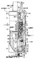
図1は本発明による固定式消火設備の消火用散水ノズルの実施形態の断面図である。
図1において本発明の消火用散水ノズル1は、ノズル本体2の上部に消火液または消火用水を加圧供給する給水管に接続する接続ネジ部3を有し、下部に火災による所定温度で離脱する感熱作動機構4を突出している。ノズル本体2は、上部よりケース2a,2b,2c及び2dを順次ねじ込み固定した円筒状の部材で構成される。
【0022】
ノズル本体2の上部の接続ネジ部3内には加圧された消火液または消火用水を流入する流入路5が形成されており、流入路5の途中の弁座11aの部分に軸12の先端に一体に形成した弁体11を定常監視状態で配置して、流入路5を閉じている。この弁体11による流入路5の閉鎖で分けられた一次側流入路5aには第1ストレーナ13が配置され、一方、二次側流入路5bには第2ストレーナ14が配置されている。第1ストレーナ13と第2ストレーナ14は、消火液または消火用水中のゴミを除去し、後述する駆動部6やノズル部8にゴミがつまるのを防ぐ。
【0023】
一次側流入路5aに配置した第1ストレーナ13は消火液または消火用水の中に浸されていることから、錆びにくい荒い網目のものを使用している。これに対し二次側流入路5b側の第2ストレーナ14にあっては、大気中に開放していることから錆びにくく、従って細かい網目のものを使用している。このような弁体11で閉じた流入路5の一次側と二次側に分けて一次側に荒い網目の第1ストレーナ13を配置することで、ストレーナの腐食をしにくくし、耐久性を高めている。
【0024】
弁体11で閉鎖した流入路5に続いては駆動部6が設けられている。駆動部6は、ケース2bの内部に一体形成したハウジング16に装着したベアリング17の外側に回転自在に支持したケーシング6bに一体に複数枚のインペラ6aを形成しており、弁体11を開くことで流入路5から流入した水流をインペラ6aで受けてケーシング6bを回転駆動できるようにしている。
【0025】
駆動部6の内部には減速部7が設けられている。減速部7としてこの実施形態にあっては、ダブル遊星歯車機構が設けられている。即ち、ケース2bのハウジング16に対しねじ込み固定した中心に弁体11の軸12を通したハウジング15にサンギア18aを固定し、サンギア18aの外側にプラネタリギア19を噛み合わせ、プラネタリギア19に駆動部6のケーシング6bに固定したインターナルギア21を噛み合わせている。プラネタリギア19はネジシャフトによりキャリアケース20に回転自在に装着されている。
【0026】
続いてハウジング15の外側にサンギア18aと同様、サンギア18bが固定され、サンギア18bにはプラネタリギア22が噛み合っており、プラネタリギア22にはキャリアケース20に固定したインターナルギア23が噛み合っている。
プラネタリギア22はネジシャフトによりキャリアケース24に連結されており、キャリアケース24がダブル遊星歯車機構の減速した出力回転を取り出す出力部となる。減速回転の出力部となるキャリアケース24の下端は、破線のようにノズル本体2の下方に延在されて固定ガイド25を一体に形成している。
【0027】
図2は図1の減速部7に設けているダブル遊星歯車機構を取り出している。このダブル遊星歯車機構にあっては、サンギア18aが固定されており、サンギア18aに噛み合わせたプラネタリギア19を介して駆動部6の回転をインターナルギア21で入力している。プラネタリギア19はキャリアケース20に回転自在に装着され、キャリアケース20は2段目のインターナルギア23に回転を伝える。
【0028】
インターナルギア23の内側にはプラネタリギア22が設けられ、サンギア18aと同様に、固定されたサンギア18bに噛み合っている。プラネタリギア22はキャリアケース24に回転自在に装着され、キャリアケース24が駆動部6の入力回転を減速した出力回転を外部に取り出す。
再び図1を参照するに、上部に弁体11を備えた軸12の下端は、減速部7を装着しているハウジング15を貫通して下方に取り出され、先端に止めネジ35によりリテーナ34を装着し、キャリアケース24側のストッパ部材29との間にスプリング30を組み込んでいる。スプリング30は図示の状態で圧縮され、ストッパ部材29に対しリテーナ34側を下方に付勢している。
【0029】
駆動部6の内側に設けた減速部7に続いては、ノズル部8が設けられている。ノズル部8は先端を台形円錐に絞り込んだ円筒体であり、この実施形態にあっては、第1部材8A、第2部材8B及び第3部材8Cを組み合わせた分割構造を持っている。
ノズル部8の上部側にフランジ部を形成している第1部材8Aは、上部外周面に形成した溝に四フッ化エチレン樹脂シート32(以下「シート32」という)を装着しており、シート32の装着面と反対側の面をストッパ面36としている。シート32は感熱作動機構4が熱分解により脱落してノズル部8が下降した時、下部のケース2dの上部内縁のシート圧着段部33に接触してノズル部8の周囲の空間から下側に水流が漏れ出すのを防ぐ。
【0030】
またシート圧着段部33に続いてはストッパボール37が組み込まれており、ノズル部8が下降した時、上部の鍔部の下側に位置するストッパ面36がストッパボール37に当接して抜け止めされる。ノズル部8は減速部7の減速回転が出力されるキャリアケース24から延在した固定ガイド部25を破線のように軸方向に貫通してガイド部を備えており、感熱作動機構4が脱落するとスプリング30の押圧と自重で固定ガイド部25に沿って下降し、ノズル本体2の下部のケース2dの下端より外部にノズル部8が突出される。
【0031】
第1部材8A,第2部材8B及び第3部材8Cを組み合わせた構造のノズル部8は、軸方向に沿った各部材の組合せ面に複数のスリット穴10を開口している。
感熱作動機構4は、ノズル部8を図示の収納位置に保持する支持プレート42をロックボール38を介して下側に組み付けたプッシャプレート43で支持しており、プッシャプレート43は中心部を断熱材40を介して集熱板44に支持されており、更に集熱板44はヒューズ47によってネジ穴付きの取付フランジ48に固定している。
【0032】
取付フランジ48はプッシャプレート43に中央下部より延在したネジ部49にねじ込み固定されている。更に集熱板44の上部には2枚の集熱板45,46が組み付けられている。この感熱作動機構4にあっては、火災による熱を受けて所定温度に上昇するとヒューズ47が溶け、ロックボール38を支持しているプッシャプレート43が脱落し、これに伴って支持プレート42も脱落し、ノズル部8の保持が解除されて下方に突出するようになる。
【0033】
ここで図1の消火用散水ノズル1にあっては、駆動部6、減速部7、及びノズル部8を、エンジニアリングプラスチックの成形部材で構成している。本発明の消火用散水ノズル1に使用するエンジニアリングプラスチックは、通常のプラスチックでは限界があった機構部品や機能部品としても十分に使用に耐える機械的性質と耐熱性をもった金属材料を凌駕する素材であり、通常、エンプラとして知られている。
【0034】
特に本発明にあっては、機械的性質と耐熱性がより高いスーパーエンジニアリングプラスチック(スーパーエンプラ)を使用する。このスーパエンジニアリングプラスチックは、機械的性質として500Kgf/cm2 以上の引張強さで2万Kgf/cm2 以上の曲げ弾性率を有し、耐熱性として150℃以上の熱変形温度を有する。
【0035】
各種のスーパーエンジニアリングプラスチックの内、本発明は、特に耐熱性に注目することで、カーボンフィラーCF30重量%含有のポリエーテルニトリルPENT、ポリエーテルエーテルケトンPEEK、又はポリフェニレンサルファイドPPSを使用する。
即ち、駆動部6及び減速部7は、ノズル本体2内に収納され、作動後は水の供給を受けることから、熱変形温度260℃以上のポリフェニレンサルファイドPPSを使用する。これに対しノズル部8は、火災時に熱気流に直接さらされるため、熱変形温度330℃以上のポリエーテルニトリルPENTや熱変形温度326℃以上のポリエーテルエーテルケトンPEEK等の耐熱性の高いものを使用する。
【0036】
このように駆動部6、減速部7及びノズル部8にエンジニアリングプラスチック、特に耐熱性の高いスーパーエンジニアリングプラスチックの樹脂成形部材を使用したことで、部品が高い精度で容易に制作でき、安定した駆動、減速及び散水ができる。またエンジニアリングプラスチックの成形部材は、摩擦係数が小さく、摩耗性にも優れ、動作がスムーズである。
【0037】
特に減速部7は、図2のように多数の歯車を備えたダブル遊星機構であり、各歯車がエンジニアリングプラスチックの成形品として高い精度で容易に制作でき、金属加工の場合に比べ製作コストを大幅に低減できる。
またノズル部8は、後の説明で明らかにするように、スリット穴10の配列部分を通る面で複数の部材8A,8B,8Cに分割してエンジニアリングプラスチックにより樹脂成形し、各分割部材8A〜8Cの組合わせ面に複数の溝を形成して組み合わせてスリット穴10を形成する。この場合、エンジニアリングプラスチックの成形部材は、面接触するように組合わせた場合、エンジニアリングプラスチック接触面に接着性があり、分割された部材の隙間から水が漏れ出すことがない。
【0038】
更に、駆動部6、減速部7及びノズル部8に使用するエンジニアリングプラスチックは、耐薬品性にも優れているため、長期間に亘り装置の信頼性が維持できる。勿論、射出成形により大量生産でき、後加工も不要のため、低価格で生産できる。更にまた、ある程度部品の一体化が図れるため、部品点数が少なくなり、組立コストも下がる。
【0039】
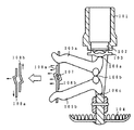
図3は、図1の感熱作動機構4が火災による所定温度で離脱しノズル部8が突出した消火液または消火用水の放水動作状態の断面図である。
火災による所定温度への上昇で図1の感熱作動機構4が熱分解により脱落すると、スプリング30の力及びノズル部8の自重によりノズル部8が図示のようにノズル本体2の下部に突出し、同時に軸12も下降して弁体11が弁座11aから離れて、それまで閉じていた流入路5を開く。このため、接続ネジ部3側に接続している図示しない給水配管からの加圧された消火液または消火用水は矢印のように流入路5を通って駆動部6の周囲に流れ込み、インペラ6aを水流が通ることで回転力を発生してケーシング6bが回転する。
【0040】
駆動部6の回転は内側に設けた減速部7により減速され、減速回転がキャリアケース24より延在した固定ガイド部25に伝えられる。このときノズル部8は固定ガイド部25に沿って下側に下降した図示の位置にあり、減速部7のキャリアケース24の減速回転を固定ガイド部25を介して受けることで、例えば水量が40リットル/分だとすると1rpm程度で減速回転される。
【0041】
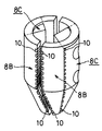
駆動部6を通った水流は固定ガイド部25の部分からノズル部8の内部に流れ込み、中心から外側方向に直線溝の形成で開口しているスリット穴10より外部に散水される。図4は図1に示した本発明の消火用散水ノズル1に設けているノズル部8の組立分解図である。本発明のノズル部8は、中央に位置するノズル部本体となる第1部材8A、第1部材8Aの下側の空洞部に両側から組み付けられる一対の第2部材8B、第2部材8Bのそれぞれの外側に組み付けられる一対の第3部材8Cで構成され、ボルト72とナット73により固定される。
【0042】
図5は図4の第1部材8Aの説明図であり、図5(A)が平面図、図5(B)が正面半断面図、図5(C)が側面半断面図、図5(D)が底面図である。なお図5(A)(D)については、対称構造となることから中心線の片側を表している。
この第1部材8Aは例えば図5(B)から明らかなように、上部に円板状の鍔部50を形成しており、鍔部50の上面外側にシート嵌合溝56を形成している。このシート嵌合溝56には、図1のようにシート32が装着される。鍔部50の下側には円筒部57を介して略U字型の支持アーム51が一体に形成される。
【0043】
円筒部57の内部には図1に示した減速部7のキャリアケース24より延在した固定ガイド部25が収納されるスライド溝52が形成され、その内側が流入路53となっている。下部に設けた支持アーム51は先端に位置決め突起54を形成しており、その下側に受け穴55が形成され、受け穴55には図1の感熱作動機構4に設けている支持プレート42の中心部の突起が嵌合される。
【0044】
円筒部57の内側に形成したスライド溝52は、図5(A)の平面図から明らかなように扇形に開口されており、この部分に図1のキャリアケース24より延在した断面円弧状の固定ガイド部25が位置する。
図6は図5に示した第1部材8Aの支持アーム51の両側に組み付けられる第2部材8Bと第3部材8Cの組立アッセンブリィである。この組立アッセンブリィから明らかなように、本発明にあっては、ノズル部8に形成するスリット穴10の配列方向に沿って第1部材8A、第2部材8B及び第3部材8Cに分割することを基本としている。このためスリット穴10は、各分割部材の組合せ面に内側の流入路から外側に向かって溝加工することにより形成できる。
【0045】
図7は図6の組立アッセンブリィにおける第2部材8Bの説明図である。ここで図7(A)は内側から見た正面図、図7(B)はそのX−X断面図、図7(C)は外側から見た背面図、図7(D)は平面図、図7(E)は底面図である。
このような第2部材8Bは、内側の組合せ面60にスリット穴10を形成する複数の直線溝を所定方向に形成している。このような組合せ面60に対する直線溝の形成によりスリット穴10が形成できるため、スリット穴10の開口及び方向についても簡単な直線溝加工で自由に形成することができる。
【0046】
第2部材8Bの上部には、図7(B)のX−X断面から明らかなように鍔部63が延在しており、鍔部63の下側を切り欠いて図8に示す第3部材の組合せ面70aを形成している。また第2部材8Bの内側は流入路65を形成しており、流入路65の下部に、図5に示した第1部材8Aの支持アーム51側の位置決め突起54に嵌合する位置決め凹部61を形成している。更に図7(C)のように、外周側に図8の第3部材8Cを組み付けるための組合せ面62を加工したことで、内側の流入路65に開放する開口部64が形成されている。
【0047】
図8は図6の第3部材8Cの説明図である。ここで図8(A)は内側から見た正面図、図8(B)はY−Y断面図、図8(C)は外側から見た背面図、図8(D)は図8(A)の左側の組合せ面70bを正面に見た図、図8(E)は組合せ面70b側の図8(A)の側面図、図8(F)は平面図、図8(E)は底面図である。
【0048】
この第3部材8Cは平面的に見ると扇形形状を持ち、内側の組合せ面70a,70bのそれぞれに図8(A)のように所定の散水方向に向けて直線溝を形成することで、複数のスリット穴10を形成している。このスリット穴10についても、図8(E)の組合せ面70bの側面図から明らかなように、中心から外側に向かって任意の放射角度による直線溝の加工で任意の大きさと方向を持つスリット穴10を容易に形成することができる。
【0049】
また第3部材8Cにはボルト通し穴71が外側より2箇所に形成されており、図4のように、両側に位置する第3部材8Cに対しボルト72とナット73により、間に第1部材8Aを中心に両側に第2部材8Bを配置して組み付けることで、図1のようなノズル部8の組立構造を得ることができる。このような第1部材8A、第2部材8B及び第3部材8Cの組立体でなるノズル部8によれば、平面から見て周囲の6箇所に向けて軸方向に並んだスリット穴10の配列が形成される。
【0050】
この場合、スーパーエンジニアリングプラスチックの成形部材である第1部材8A、第2部材8Bおよび第3部材8Cは、面接触するように組合された場合、スーパーエンジニアリングプラスチックの接触面に接着性があるため、分割された部材の隙間から水が漏れ出すことがない。
図9は図3に示した本発明の消火用散水ノズル1の作動状態における散水パターンの説明図である。天井面に設置された本発明の消火用散水ノズルが火災による熱を受けて作動すると、図示のようにノズル部8が突出した状態で周囲6箇所に配列しているスリット穴より供給された消火液または消火用水の放水による放水パターン80が得られる。
【0051】
このノズル部8からの放水パターン80によって、所定の防護範囲82に6方向に向いた棒状の散布パターン81a,81bが得られ、このときノズル部8は放水による水流を受けて駆動部6の回転により矢印方向に回転し、その結果、各散布パターン81は防護範囲82を1rpm程度の低速度で回転走査することになる。
【0052】
ノズル部8のスリット穴10が縦方向に配列しているので、実際にはノズル部8からの放水はスポット状の散水パターンが連続的に並んだ散布パターンとなるが、各スポット状の散水パターンが消火対象面に当った際に飛散、および消火対象面を流れることにより、スポット状の散水パターンが広がって隣同志が繋った帯状の散布パターン81となる。
【0053】
このように帯状の散布パターン81にするために、第2部材、第3部材に形成するスリット穴10の溝の方向をそれぞれ設定している。つまり、図7、図8に示すように、第2部材、第3部材に形成するスリット穴10につき、遠くに散水するヘッド部8の上側のスリット穴10は横方向に溝を形成し、近くに散水するヘッド部8の下側のスリット穴10は下方向に形成する。そして、スポット状の散水パターンが消火対象面に散水される際に繋って帯状の散布パターン81になるように、それぞれスリット穴10の溝の方向を設定する。
【0054】
尚、スリット穴10の大きさを変えることで、一つのスリット穴10から放水される消火液の量を変えることができる。ノズル部8の上側のスリット穴10は、消火用散水ノズル1の位置から離れた防護範囲に散水するため、スリット穴10を近距離に散水する下側のスリット穴10よりも大きくして、水量を多くして遠くに散水する。
【0055】
通常、ノズル部8は直径2cm程度の小さなものであるから、それぞれが方向、穴の大きさが相違する複数のスポット穴を1個の円柱部材に形成しようとしても、技術上困難である。ところが、本発明のような溝を形成した分割部材を組立てることにより、容易に複数の穴の開いた小さいノズル部8を形成することができる。
【0056】
ここで図6の組立アッセンブリィから明らかなように、第2部材8Bの組合せ面のスリット穴10は、その間に入る図5の第1部材8Aの支持アーム51との組合せで軸方向に2列のスリット穴10を形成することとなり、この2列のスリット穴は近接していることから、図9の散布パターンにあっては、1つの棒状の散布パターン81aとなり、一列のスリット穴10の散布パターン81bに比べるとその幅が広くなる。
【0057】
尚、減速部7を設けた理由は、ノズル部8を駆動部6のケーシング6bのみで回転させると、かなりの高速でノズル部8が回転してしまい、ノズル部8から散水された消火用水は塊状から粒状に分散し、防護範囲内の特定部分に集中的に散水する散布パターンが形成できなくなり、防護範囲のある一点から見ると一回の走査で到達する消火用水の水量が少なくなり、粒子径も小さくなり、また消火用水の打力も低減して消火能力が低下してしまうからである。
【0058】
これを防止し、集中的に散水する散布パターンを形成するため散布パターンの走査の速度を散布パターンの走査の形状が維持できる程度の比較的低速度にする必要があるために減速部7を設けている。
図10は図9の防護範囲82内のある一箇所から見た散水量の時間的変化であり、図10(A)は従来の消火用散水ノズルの散水量であり、図10(B)が本発明の消火用散水ノズルの散水量である。
【0059】
図10(A)の従来の消火用散水ノズルにあっては、防護範囲82のある一箇所から見ても常に一定の水量の水が散水されている。これに対し図10(B)の本発明の消火用散水ノズルにあっては、散布パターン81a,81bの回転走査速度に依存した一定の周期で間欠的に大量の水が散水されることになる。
このように本発明の消火用散水ノズルを用いると、防護範囲82のある一部分から見た場合に、火災に対して瞬間的には従来の散水ノズルよりも大量の消火用水または消火液が散水され、一定水量を継続して散水するよりも瞬間的に集中して大量の水を散水した方が高い消火能力が得られる。このため、例えば従来の80リットル/分の防護範囲82の全域放射の散水ノズルと例えば本発明による消火ノズルで散水量を40リットル/分、走査速度を1rpm程度とした場合と比較すると、防護範囲82の全体的に見て少ない水量にも関わらず、より高い消火能力が得られる。
【0060】
また本発明の消火用散水ノズルにあっては、少ない散水量で消火できるため、いわゆる水損の被害を小さくすることができる。このことから、消火用水の水槽も小さくでき、更に従来の消火能力と同等とした場合には、従来よりも配管内の水圧を抑えることができるため、消火ポンプが小容量で済み、更には自家発電設備などのバックアップ設備も小容量とでき、配管サイズも小さくなるために、設備コストを大幅に低減できる。
【0061】
また防護範囲82内のある一箇所から見れば、従来のように防護範囲82内全体に散水するのと比べ、本発明にあっては、瞬間的には散水量が増えると同時に消火対象物に到達する水の打力及び粒子径も増すので、消火能力が増大する。
即ち本発明においては、水は分散された粒状ではなく特定の部分に集中的に散水される打力の強い水の塊として消火対象物に散水されるため、火災気流に負けることなく火災深部まで到達して消火能力が高くなる。
【0062】
このため、火災抑制までの時間が短くて済み、したがって鎮火までの水量も少なくて済む。更に塊状態の水で消火するため、一度消火した部分が再び燃え上がることがなくなり、一度消火された場所を継続して鎮火状態にできる。
図11は本発明の散水による消火の様子を従来と対比して示している。図11(C)は従来の散水パターンであり、従来の散水能力では防護範囲82全体に均一に散水させるため、消火用水をデフレクタで分散させて粒状にして散水しており、防護範囲82内に比較的粒子径の小さな様々な大きさをもった粒状の水によるスポット状散布パターン84が得られる。
【0063】
そのため火災の勢いが強い場合には、分散された水は粒子径が小さいため火災の気流に負け、炎83の深部に達する前に蒸発し火災の抑制に時間が掛かり、また全く消火できないこともある。このため消火用水の量も多くなり、水損による被害も大きくなる。
更に防護範囲82内のある一点から見ると、粒状の水により一瞬、その一点の火災の炎83が弱まったとしても、その時点の付近の炎83により一度掛かった水が蒸発し、付近の炎によって再び燃え始める。このため、完全に消火するまでには時間が掛かる。
【0064】
図11(A)(B)は本発明による帯状の散布パターンの散水であり、防護範囲82内のある部分に集中的に大量の消火用水を散水する散布パターン81を形成している。このため、瞬間的には散水量が増えると同時に、消火対象物に当たる消火用水の打力及び粒子径も増すので、消火能力が増大する。
即ち、本発明の散布パターン81においては、消火用水は図11(C)のように分散された粒状ではなく、特定の部分に集中的に散水される打力の強い水の塊として消火対象物に散水される。このため、火災気流に負けることなく炎83の深部まで到達して消火能力が高くなり、火災抑制までの時間が短くて済み、したがって鎮火までの水量も少なくて済む。
【0065】
また図11(B)のように、散布パターン81で防護範囲82の全域を走査して塊状の水で消火するため、一度消火した鎮火部分85が再び燃え上がることを抑え、一度消火された場所を継続して鎮火状態に維持できる。
更に防護範囲82内のある部分に大量の水を散水するようにノズル部8を形成したため、防護範囲82を従来の散水ノズルと比べて大きくした場合でも、走査時間を調整することにより火災に対しては瞬間的には大量の水を散水することができ、従来と同等以上の消火性能が得られることから、従来の散水ノズルに比べノズルの設置個数を減らすことができる。
【0066】
例えば取付ピッチ2.3メートルで所定の防護範囲82に8個の散水ノズルを従来設置していた場合に対し、本発明によれば、取付ピッチを2.6メートルとすることができ、その結果、設置する散水ノズルの個数を4個に減らすことができる。
図12はノズル部8から散水される散布パターン81の別の形態を示す。図12(A)はノズル部8の周方向に90°の間隔をおいて4個の半径部となるスリットを形成した場合であり、防護範囲82に対し帯状の散布パターン81をクロスさせた十字形状の散布パターンが得られる。
図12(B)はノズル部8に180°の間隔をおいて2つの半径部となるスリットを形成した場合であり、防護範囲82において直径方向に帯状の散布パターン81が得られる。更に図12(C)はノズル部8の周方向に10°程度の短い角度間隔をおいて3つの半径部となるスリットを形成した場合であり、この場合には防護範囲82において半径方向に放射状に広がった3つの散布パターン81を得ることができる。
【0067】
尚、上記の実施形態は、定常監視状態で流入路を閉鎖し火災時に作動して流入路を開く閉鎖型の消火用散水ノズルを例にとるものであったが、常時流入路を開放している開放型の消火用散水ノズルについてもそのまま適用できる。開放型消火用散水ノズルにあっては、例えば図1の弁体11を備えた軸12が不要となり、減速部7に対しノズル部8を固定し、且つノズル部8をノズル本体2に対し常時下方に突出した構造とすればよい。
【0068】
また上記の実施形態は、図4のようにノズル部8を1つの第1部材8A、2つの第2部材8B、及び2つの第3部材8Cに分割する場合を例にとっているが、ノズル部8の外周軸方向に配列するスリット穴に沿った位置を分割して組合せ面とすることで、任意の散布パターンに対応した分割構造とできる。
例えば、円筒形状のノズル部に、スリット穴10が配列される箇所に沿ってスリットを設けるように切り欠き、この切り欠いたスリットの形状に合うチップを用意し、チップにスリット穴10に対応する溝を設け、チップをノズル部のスリットに嵌め込むことで、スリット穴10が配列したノズル部を形成するような分割構造としても良い。
【0069】
また図4の分割構造を維持したまま各部材の組合せ面に直線溝を形成するか否か選択することで、スリット穴の配列位置を変化させて散布パターンの数を適宜に決めることもできる。
更に、スリット穴10の形状は、四角に溝を形成するに限らず、半円や三角形状などでも良い。
【0070】
また上記の実施形態にあっては、消火用散水ノズルのノズル部、駆動部及び減速部をエンジニアリングプラスチックの成形部材で構成する場合を例とるものであったが、ノズル部と駆動部又はノズル部のいずれか一方をエンジニアリングプラスチックの成形部材で構成するようにしてもよい。更に上記の実施形態では、スーパーエンジニアリングプラスチックとして、カーボンフィラー30重量%含有のポリエーテルニトリルPENT、ポリエーテルエーテルケトンPEEK、又はポリフェニレンサルファイドPPSを使用しているが、本発明はこれに限定されず、ノズル部、駆動部及び減速部に要求される機械的性質と耐熱性を満たすものであれば、適宜のスーパーエンジニアリングプラスチックを使用することができる。
【0071】
【発明の効果】
以上説明してきたように本発明によれば、防護範囲内にある部分を塊状の水で複数のスポット状の散布パターンを連続的に並べて帯状の散布パターンを形成し、この帯状の散布パターンの形状が維持できる速度に減速して防護範囲内を走査するようにしたので、火災に対して瞬時的には大量の消火液または消火用水が散布されるため、より高い消火能力が得られ、水損の被害も小さくなる。
【0072】
また従来と同程度の消火能力とした場合には、配管内の水圧を低くでき、水槽、ポンプなどの容量も少なくて済み、更に配管サイズも小さくなり、更に防護範囲内のある部分に集中的に散水するようにノズル部を形成しているために、防護範囲を従来より広くしても従来と同程度の消火能力が維持でき、このためノズルの設置個数も低減でき、その結果、設備コストを低減することができる。
【0073】
更にノズル部を列状に並んだスリット穴の配列部分を通る面で複数の部材に分割し、各分割部材の組合せ面にスリット穴を形成する複数の直線溝を加工形成して組み合わせたことで、ノズル部の外周面に任意の散布方向を持って配列される複数のスリット穴の加工形成が容易にでき、防護区域に対するノズル部からの散布パターンを必要に応じて任意の方向、位置、形状とすることが自由にできる。
【0074】
本発明の消火用散水ノズルは、駆動部と減速部及び又はノズル部にエンジニアリングプラスチック、特に耐熱性の高いスーパーエンジニアリングプラスチックの成形部材を使用したことで、部品が高い精度で容易に制作でき、安定した駆動、減速及び散水ができる。またエンジニアリングプラスチックの成形部材は、摩擦係数が小さく、摩耗性にも優れ、動作がスムーズにできる。
【0075】
またノズル部は、スリット穴の配列部分を通る面で複数の部材に分割してエンジニアリングプラスチックにより成形し、各分割部材の組合わせ面に複数の溝を形成して組み合わせてスリット穴を形成するが、この場合、エンジニアリングプラスチックの成形部材は、面接触するように組合わせた場合、エンジニアリングプラスチック接触面に接着性があり、分割された部材の隙間から水が漏れ出すことがない。
【0076】
更に、耐薬品性にも優れているため、長期間に亘り装置の信頼性が維持できる。勿論、射出成形により大量生産でき、後加工も不要のため、低価格で生産できる。更にまた、ある程度部品の一体化が図れるため、部品点数が少なくなり、組立コストも下がる。
【図面の簡単な説明】
【図1】本発明による消火用散水ノズルの定常監視状態における内部構造の断面図
【図2】図1の減速に使用したダブル遊星歯車機構の説明図
【図3】図1の作動状態の断面図
【図4】図1のノズル部の組立分解図
【図5】図4の第1部材の説明図
【図6】図4の第2及び第3部材の組立アッセンブリの説明図
【図7】図4の第2部材の説明図
【図8】図4の第3部材の説明図
【図9】図3の作動状態における散水動作の説明図
【図10】防護範囲の一箇所から見た本発明の散水量を従来と対比して示したタイムチャート
【図11】本発明の散布パターンによる消火の様子を従来と対比して示した説明図
【図12】本発明による散布パターンの他の形態を示した説明図
【図13】従来例を示した説明図
【符号の説明】
1:消火用散水ノズル
2:ノズル本体
3:接続ネジ部
4:感熱作動機構
5:流入路
5a:一次側流入路
5b:二次側流入路
6:駆動部
6a:インペラ
6b:ケーシング
7:減速部(ダブル遊星歯車機構)
8:ノズル部
8A:第1部材
8B:第2部材
8C:第3部材
10:スリット穴
60,62,70a,70b:組合せ面
80:放水パターン
81:散布パターン
82:防護範囲[0001]
BACKGROUND OF THE INVENTION
The present invention relates to a watering nozzle for fire extinguishing in a stationary fire extinguishing equipment used in a stationary fire extinguishing equipment such as a sprinkler fire extinguishing equipment.
[0002]
[Prior art]
Conventionally, as a water spray nozzle for fire extinguishing used in this type of sprinkler fire extinguishing equipment, water is dispersed with a deflector to spray water in a granular state in order to spray water uniformly over the entire protection range. For example, as shown in FIG. (Japanese Patent Laid-Open No. 5-69730).
[0003]
FIG. 13 shows a fusible link type fire-fusing water spray nozzle, in which a
[0004]
When the
[0005]
[Problems to be solved by the invention]
However, in such a conventional fire-extinguishing sprinkling nozzle, since it was a continuous radiation at a predetermined flow rate of, for example, 80 liters / minute or more per nozzle, a relatively large amount of fire-extinguishing liquid with respect to the fire-extinguishing capability. Or the amount of water is necessary, and naturally it is radiated to objects other than the object to be extinguished, so that there is a problem that a secondary disaster caused by the radiated fire extinguishing liquid or water, so-called water loss increases. In terms of equipment, there are problems that the water tank and the pump have a large capacity, the pipe size becomes large, and the cost of the whole equipment becomes high.
[0006]
Moreover, in the conventional watering nozzle, in order to spray water uniformly over the entire protection range, water is dispersed by a deflector to form water. Therefore, when there is a strong fire momentum, the dispersed water has a small particle size, so it will evaporate before reaching the depths of the fire by losing the fire air flow, it takes time to suppress the fire, and it cannot be extinguished at all Sometimes. For this reason, the amount of water increases and the damage caused by water loss increases.
[0007]
Furthermore, from a certain point in the protection range, even if the fire flame of one point is weakened momentarily by the granular water, the water once applied by the flame near that point evaporates, and again by the nearby flame Start to burn. For this reason, it takes time to extinguish completely.
The present invention has been made in view of such problems, and while ensuring fire extinguishing capability, reducing the amount of radiation per one watering nozzle for fire extinguishing, reducing water loss, An object of the present invention is to provide a watering nozzle for fire extinguishing of a fixed fire extinguishing equipment that can reduce the installation cost by reducing the capacity of a pump or the like.
[0008]
Another object of the present invention is to provide a fire extinguishing water spray nozzle for a fixed fire extinguishing facility that can easily and easily form a plurality of slit holes formed in a nozzle portion used for a fire extinguishing water spray nozzle.
[0009]
[Means for Solving the Problems]
In order to achieve this object, the present invention is configured as follows.
The present invention It is installed above the protection area such as the ceiling surface. Target fire extinguishing water spray nozzles for fixed fire extinguishing equipment that is connected to fire extinguishing piping to which fire extinguishing liquid or fire extinguishing water is pumped.
[0010]
As such a water spray nozzle for fire extinguishing, in the present invention, a specific part within a predetermined protection range is used. A plurality of spot-shaped spray patterns arranged as a block of water in a continuous manner to form a strip-shaped spray pattern and a plurality of lines arranged in a row to spray water intensively A swivelable nozzle part having a slit hole, a drive part for rotating a drive shaft using a water flow when sprinkling fire extinguishing liquid or water for fire extinguishing from the nozzle part, and rotation of the drive shaft of the drive part are inputted and inputted. According to the reduction ratio of At a speed that can maintain the shape of a strip-shaped spray pattern in which multiple spot-shaped spray patterns are continuously arranged A nozzle that rotates the nozzle portion by decelerating, scans the spray pattern within a predetermined protection range, and sprays water throughout the predetermined protection range. Lined up It is characterized in that it is divided into a plurality of members on a surface passing through the arrangement portion of the slit holes, and a plurality of grooves for forming the slit holes are formed and combined on the combination surface of each divided member.
[0011]
According to the fire-sprinkling water spray nozzle of the present invention having such a configuration, the portion within the protection range is removed. A plurality of spot-like spray patterns are continuously arranged in a block of water. Form a spray pattern, Decrease to a speed that can maintain the shape of this strip-shaped spray pattern. Since the scanning is performed within the protection range, a large amount of fire extinguishing liquid is radiated from a conventional watering nozzle instantaneously against a fire. Compared to the case of about 1 rpm with a rotation scan of 40 liters / minute, a higher fire extinguishing capability can be obtained despite a small amount of water in the entire protection range.
[0012]
Further, according to the present invention, the amount of water sprayed instantaneously increases, and at the same time, the striking force and particle diameter of water corresponding to the fire extinguishing target also increase, so that the fire extinguishing capability increases. That is, in the present invention, the water is not dispersed in granular form, but is sprayed on the fire extinguishing object as a mass of water with strong striking water that is intensively sprinkled on a specific part. The fire extinguishing ability becomes high by reaching the deep part of the water, and the time until fire suppression is short, so the amount of water until fire extinguishing is small. Moreover, since the fire is extinguished with water in a lump state, it is possible to suppress the part that has been extinguished once again from burning, and the fire extinguished place can be continuously put into a fire extinguisher state.
[0013]
In addition, since the fire can be extinguished with a small amount of radiation, so-called water damage damage can be reduced. Furthermore, the irradiating water tank is reduced, the pump is reduced in capacity, backup equipment such as private power generation facilities is also reduced in capacity, and the piping size is reduced, resulting in lower costs.
In addition, even when the protection range is increased compared to conventional watering nozzles, by adjusting the scanning time, a large amount of water can be radiated instantaneously against a fire, and the fire extinguishing performance is equivalent or better. Therefore, the number of nozzles installed can be reduced as compared with a conventional watering nozzle.
[0014]
Furthermore, in the present invention, the nozzle portion is Lined up By dividing into a plurality of members on the surface passing through the array portion of the slit holes, and forming a combination of grooves forming slit holes on the combined surface of each divided member, the outer peripheral surface of the nozzle portion has an arbitrary radial direction. A plurality of slit holes to be arranged can be processed and formed, and the spray pattern from the nozzle to the protective compartment can be freely set to any shape, width and position as required.
[0015]
Here, the nozzle part is a cylindrical body whose tip is narrowed into a conical shape, and the cylindrical body is divided into a plurality of members, and a straight groove that forms a slit hole in one of the combination surfaces of the divided members is flowed into the inside. A unique radiation angle is set from the road toward the outer peripheral surface to communicate with each other.
[0017]
The drive part and the speed reduction part used for the water spray nozzle for fire extinguishing according to the present invention are constituted by an engineering plastic molding member. Further, the nozzle part may be formed of an engineering plastic molding member.
As described above, the water spray nozzle for fire extinguishing of the present invention uses a molding member made of engineering plastic, particularly super engineering plastic having high heat resistance, for the driving part and the speed reducing part. Can drive, decelerate and water. Engineering plastic molded members have a low coefficient of friction, excellent wear, and smooth operation.
[0018]
In addition, the nozzle part is divided into a plurality of members on the surface passing through the array of slit holes and molded by engineering plastic, and a plurality of grooves are formed on the combined surface of each divided member to form a slit hole. In this case, when the engineering plastic molding member is combined so as to be in surface contact, the contact surface has adhesiveness, and water does not leak from the gap between the divided members.
[0019]
Furthermore, since the chemical resistance is excellent, the reliability of the apparatus can be maintained over a long period of time. Of course, it can be mass-produced by injection molding and can be produced at a low price because no post-processing is required. Furthermore, since the parts can be integrated to some extent, the number of parts is reduced and the assembly cost is reduced.
Furthermore, the watering nozzle for fire extinguishing of the present invention comprises a nozzle part, a driving part and Deceleration part May be formed of an engineering plastic molding member, in which case the nozzle portion is formed of an engineering plastic molding member having a higher thermal deformation temperature than the driving portion and the speed reduction portion. That is, since the nozzle part is directly exposed to the hot air flow in the event of a fire, In Use one with higher heat resistance than the housed drive unit and deceleration unit.
[0020]
The engineering plastic used for the drive part and / or nozzle part of the fire spray nozzle of the present invention has a mechanical property of 500 kgf / cm. 2 20,000kgf / cm at the above tensile strength 2 A super engineering plastic having the above flexural modulus and a heat distortion temperature of 150 ° C. or higher as heat resistance is used. This super engineering plastic is composed of polyether nitrile PENT and polyether ether ketone PEE containing 30% by weight of carbon filler. K Alternatively, it is desirable to use polyphenylene sulfide PPS. For example, polyphenylene sulfide PPS having a heat deformation temperature of 260 ° C. or higher is used for the driving portion and the speed reduction portion, and polyether nitrile PENT having a heat deformation temperature of 330 ° C. or higher and high heat resistance is used for the nozzle portion.
[0021]
DETAILED DESCRIPTION OF THE INVENTION
FIG. 1 is a cross-sectional view of an embodiment of a fire watering nozzle for a fixed fire fighting equipment according to the present invention.
In FIG. 1, a fire-sprinkling
[0022]
An inflow path 5 through which pressurized fire extinguishing liquid or fire extinguishing water flows is formed in the
[0023]
Since the 1st strainer 13 arrange | positioned at the
[0024]
Following the inflow path 5 closed by the
[0025]
A deceleration unit 7 is provided inside the
[0026]
Subsequently, the
The
[0027]
FIG. 2 shows the double planetary gear mechanism provided in the speed reduction unit 7 of FIG. In this double planetary gear mechanism, the
[0028]
A
Referring again to FIG. 1, the lower end of the shaft 12 having the
[0029]
Following the speed reduction unit 7 provided inside the
The
[0030]
In addition, a
[0031]
The
The heat-
[0032]
The mounting flange 48 is screwed and fixed to a screw portion 49 that extends from the lower center of the
[0033]
Here, in the fire-sprinkling
[0034]
Particularly in the present invention, a super engineering plastic (super engineering plastic) having higher mechanical properties and heat resistance is used. This super engineering plastic has a mechanical property of 500 kgf / cm. 2 20,000kgf / cm at the above tensile strength 2 It has the above flexural modulus and has a heat distortion temperature of 150 ° C. or higher as heat resistance.
[0035]
Among various super engineering plastics, the present invention uses polyether nitrile PENT, polyether ether ketone PEEK, or polyphenylene sulfide PPS containing 30% by weight of carbon filler CF by paying particular attention to heat resistance.
That is, the
[0036]
Thus the
[0037]
In particular, the speed reducer 7 is a double planetary mechanism with a large number of gears as shown in FIG. 2, and each gear can be easily manufactured with high precision as a molded product of engineering plastic, greatly increasing the manufacturing cost compared to metal processing. Can be reduced.
Further, as will be clarified later, the
[0038]
Furthermore, the
[0039]
FIG. 3 is a cross-sectional view of the water discharge operation state of the fire extinguishing liquid or fire extinguishing water in which the
The heat-sensitive operation mechanism shown in Fig. 1 when the temperature rises to a predetermined level due to
[0040]
The rotation of the
[0041]
The water flow through the
[0042]
5 is an explanatory view of the
For example, as is apparent from FIG. 5B, the
[0043]
A fixed guide extending from the
[0044]
The
FIG. 6 shows an assembly assembly of the
[0045]
FIG. 7 is an explanatory diagram of the
Such a
[0046]
As is apparent from the XX cross section of FIG. 7B, an
[0047]
FIG. 8 is an explanatory view of the
[0048]
The
[0049]
Further, the
[0050]
In this case, the
FIG. 9 is an explanatory view of a watering pattern in the operating state of the fire-spraying
[0051]
By the
[0052]
Since the slit holes 10 of the
[0053]
Thus, in order to obtain the strip-shaped
[0054]
Note that by changing the size of the
[0055]
Usually, since the
[0056]
Here, as apparent from the assembly assembly of FIG. 6, the slit holes 10 on the combination surface of the
[0057]
The reason why the speed reduction unit 7 is provided is that if the
[0058]
In order to prevent this and form a spray pattern that sprays water intensively, the speed of the spray of the spray pattern needs to be relatively low so that the shape of the spray of the spray pattern can be maintained. ing.
FIG. 10 is a temporal change in the amount of water seen from a certain position within the
[0059]
In the conventional fire extinguishing sprinkler nozzle of FIG. 10 (A), a constant amount of water is always sprinkled even when viewed from one place with the
In this way, when the fire-sprinkling nozzle of the present invention is used, a large amount of fire-fighting water or fire-fighting liquid is sprinkled from a conventional watering nozzle instantaneously against a fire when viewed from a certain part of the
[0060]
Moreover, since the fire-sprinkling nozzle of the present invention can be extinguished with a small amount of water, so-called water damage damage can be reduced. Because of this, the water tank for fire extinguishing can be made smaller, and if it is equivalent to the conventional fire extinguishing capacity, the water pressure in the piping can be suppressed more than before, so the fire extinguishing pump can be of a small capacity, and even private Backup equipment such as power generation equipment can also have a small capacity, and the piping size can be reduced, so the equipment cost can be greatly reduced.
[0061]
Further, when viewed from a certain point within the
That is, in the present invention, the water is not dispersed in a granular form, but is sprayed on the fire extinguishing object as a strong batting water mass that is intensively sprayed on a specific portion, so that it can reach the deep part of the fire without losing the fire air current. Reach and increase fire fighting ability.
[0062]
For this reason, the time until fire suppression is short, and therefore the amount of water until fire suppression is small. Furthermore, since the fire is extinguished with water in a lump state, the part once extinguished is not burned again, and the place once extinguished can be kept in a fire extinguished state.
FIG. 11 shows the state of fire extinguishing by watering according to the present invention in comparison with the prior art. FIG. 11C shows a conventional watering pattern. In the conventional watering capacity, water for fire extinguishing is dispersed by a deflector in order to spray water uniformly throughout the
[0063]
For this reason, when the momentum of the fire is strong, the dispersed water has a small particle size, so it loses the fire air flow, evaporates before reaching the deep part of the
Further, when viewed from a certain point within the
[0064]
FIGS. 11A and 11B show water sprays in a strip-like spray pattern according to the present invention, and a
That is, in the
[0065]
Further, as shown in FIG. 11 (B), since the
Furthermore, since the
[0066]
For example, in the case where eight watering nozzles are conventionally installed in a
FIG. 12 shows another form of the
FIG. 12B shows a case where slits that are two radius portions are formed in the
[0067]
The above embodiment is an example of a closed fire extinguishing sprinkling nozzle that closes the inflow channel in a steady monitoring state and operates in the event of a fire to open the inflow channel. The present invention can also be applied as it is to the open type watering nozzle for fire extinguishing. In the case of the open type watering nozzle for fire extinguishing, for example, the shaft 12 having the
[0068]
In the above embodiment, the
For example, a cylindrical nozzle portion is cut out so as to provide slits along the positions where the slit holes 10 are arranged, and a chip that matches the shape of the cut-out slit is prepared, and the chip corresponds to the
[0069]
In addition, by selecting whether or not to form straight grooves on the combined surfaces of the respective members while maintaining the divided structure of FIG. 4, the number of spraying patterns can be appropriately determined by changing the arrangement positions of the slit holes.
Furthermore, the shape of the
[0070]
Further, in the above embodiment, the nozzle part of the watering nozzle for fire extinguishing, the drive part, and Deceleration part However, the nozzle portion and the driving portion or the nozzle portion may be formed of an engineering plastic molding member. Furthermore, in the above embodiment, as super engineering plastic, polyether nitrile PENT, polyether ether ketone PEEK, or polyphenylene sulfide PPS containing 30% by weight of carbon filler is used, but the present invention is not limited to this, Nozzle, drive, and Deceleration part Any super engineering plastic can be used as long as it satisfies the mechanical properties and heat resistance required.
[0071]
【The invention's effect】
As described above, according to the present invention, the portion within the protection range is selected. A plurality of spot-like spray patterns are continuously arranged in a block of water. Form a spray pattern, Decrease to a speed that can maintain the shape of this strip-shaped spray pattern. Since the scanning is performed within the protection range, since a large amount of fire extinguishing liquid or water for fire extinguishing is instantaneously applied to the fire, higher fire extinguishing ability can be obtained and damage of water loss is reduced.
[0072]
If the fire extinguishing capacity is comparable to the conventional one, the water pressure in the pipe can be lowered, the capacity of the water tank, pump, etc. can be reduced, the pipe size can be further reduced, and it can be concentrated on a part within the protection range. Since the nozzle part is formed to spray water, it is possible to maintain the same level of fire extinguishing capability as before, even if the protection range is wider, so the number of nozzles installed can be reduced, resulting in equipment costs. Can be reduced.
[0073]
Furthermore, the nozzle part Lined up Dividing into a plurality of members on the surface passing through the array part of the slit holes, and combining and forming a plurality of linear grooves forming slit holes on the combination surface of each divided member, the outer peripheral surface of the nozzle part A plurality of slit holes arranged with a spraying direction can be easily processed and formed, and the spraying pattern from the nozzle portion with respect to the protection area can be freely set in any direction, position and shape as required.
[0074]
The watering nozzle for fire extinguishing of the present invention comprises a drive unit, a speed reduction unit and / or Nozzle part In addition, by using molded parts of engineering plastic, especially super engineering plastic with high heat resistance, parts can be easily produced with high accuracy, and stable driving, deceleration and watering can be performed. Engineering plastic molded members have a low coefficient of friction, excellent wear, and smooth operation.
[0075]
In addition, the nozzle part is divided into a plurality of members on the surface passing through the array portion of the slit holes and molded by engineering plastic, and a plurality of grooves are formed on the combined surface of each divided member to form a slit hole. In this case, when the engineering plastic molding member is combined so as to be in surface contact, the engineering plastic contact surface has adhesiveness, and water does not leak from the gaps between the divided members.
[0076]
Furthermore, since the chemical resistance is excellent, the reliability of the apparatus can be maintained over a long period of time. Of course, it can be mass-produced by injection molding and can be produced at a low price because no post-processing is required. Furthermore, since the parts can be integrated to some extent, the number of parts is reduced and the assembly cost is reduced.
[Brief description of the drawings]
FIG. 1 is a cross-sectional view of the internal structure of a fire-fighting watering nozzle according to the present invention in a steady monitoring state.
FIG. 2 is an explanatory diagram of a double planetary gear mechanism used for reduction in FIG.
3 is a cross-sectional view of the operating state of FIG.
4 is an exploded view of the nozzle portion of FIG.
5 is an explanatory diagram of the first member in FIG. 4;
6 is an explanatory view of the assembly assembly of the second and third members of FIG. 4;
7 is an explanatory diagram of the second member in FIG. 4. FIG.
FIG. 8 is an explanatory diagram of the third member in FIG.
9 is an explanatory diagram of watering operation in the operating state of FIG. 3;
FIG. 10 is a time chart showing the watering amount of the present invention as seen from one place of the protection range in comparison with the conventional one.
FIG. 11 is an explanatory diagram showing how fire extinguishing is performed according to the spray pattern of the present invention in comparison with the conventional one.
FIG. 12 is an explanatory view showing another form of the spray pattern according to the present invention.
FIG. 13 is an explanatory diagram showing a conventional example.
[Explanation of symbols]
1: Sprinkling nozzle for fire extinguishing
2: Nozzle body
3: Connection thread
4: Thermal operation mechanism
5: Inflow channel
5a: Primary inflow path
5b: Secondary side inflow path
6: Drive unit
6a: Impeller
6b: casing
7: Reducer (double planetary gear mechanism)
8: Nozzle
8A: First member
8B: Second member
8C: Third member
10: slit hole
60, 62, 70a, 70b: combination surface
80: Water discharge pattern
81: Scatter pattern
82: Protection range
Claims (7)
所定の防護範囲内の特定部分に塊状の水として複数のスポット状の散布パターンを連続的に並べて帯状の散布パターンを形成し集中的に散水する列状に並んだ複数のスリット穴を備えた旋回自在なノズル部と、
前記ノズル部から前記消火液又は消火用水を散水する際の水流を駆動源として駆動軸を回転させる駆動部と、
前記駆動部の駆動軸の回転を入力し所定の減速比に従って前記複数のスポット状の散布パターンが連続的に並んだ帯状の散布パターンの形状が維持できる速度に減速して前記ノズル部を回転させ、前記散布パターンを前記所定の防護範囲内を走査して前記所定の防護範囲内全域に散水させる減速部と、
を備え、
前記ノズル部を列状に並んだスリット穴の配列部分を通る面で複数の部材に分割し、各分割部材の組合せ面に前記スリット穴を形成する複数の溝を形成して組み合わせたことを特徴とする消火用散水ノズル。 In the watering nozzle for fire extinguishing of fixed fire extinguishing equipment that is installed above the protection area such as the ceiling surface and is connected to the fire extinguishing pipe to which the fire extinguishing liquid or fire extinguishing water is pumped.
Swirling with a plurality of slit holes arranged in a row to form a strip-like spray pattern by continuously arranging a plurality of spot-like spray patterns as a block of water in a specific part within a predetermined protection range A flexible nozzle,
A drive unit that rotates a drive shaft using a water flow when the fire extinguishing liquid or fire water is sprinkled from the nozzle unit as a drive source; and
The rotation of the drive shaft of the drive unit is input, and the nozzle unit is rotated at a speed that can maintain the shape of the strip-shaped spray pattern in which the plurality of spot-shaped spray patterns are continuously arranged according to a predetermined reduction ratio. A speed reducer that scans the spray pattern within the predetermined protection range and sprays water throughout the predetermined protection range;
With
The nozzle portion is divided into a plurality of members on a surface passing through an array portion of slit holes arranged in a row, and a plurality of grooves for forming the slit holes are formed and combined on a combination surface of each divided member. Sprinkle nozzle for fire extinguishing.
Priority Applications (1)
| Application Number | Priority Date | Filing Date | Title |
|---|---|---|---|
| JP08138698A JP3672726B2 (en) | 1997-06-30 | 1998-03-27 | Watering nozzle for fire extinguishing of fixed fire extinguishing equipment |
Applications Claiming Priority (3)
| Application Number | Priority Date | Filing Date | Title |
|---|---|---|---|
| JP17361097 | 1997-06-30 | ||
| JP9-173610 | 1997-06-30 | ||
| JP08138698A JP3672726B2 (en) | 1997-06-30 | 1998-03-27 | Watering nozzle for fire extinguishing of fixed fire extinguishing equipment |
Related Child Applications (2)
| Application Number | Title | Priority Date | Filing Date |
|---|---|---|---|
| JP2000297942A Division JP3887157B2 (en) | 1997-06-30 | 2000-09-29 | Watering nozzle for fire fighting |
| JP2005027304A Division JP2005152669A (en) | 1997-06-30 | 2005-02-03 | Sprinkler nozzle for fire extinguishing |
Publications (2)
| Publication Number | Publication Date |
|---|---|
| JPH1170184A JPH1170184A (en) | 1999-03-16 |
| JP3672726B2 true JP3672726B2 (en) | 2005-07-20 |
Family
ID=26422410
Family Applications (1)
| Application Number | Title | Priority Date | Filing Date |
|---|---|---|---|
| JP08138698A Expired - Lifetime JP3672726B2 (en) | 1997-06-30 | 1998-03-27 | Watering nozzle for fire extinguishing of fixed fire extinguishing equipment |
Country Status (1)
| Country | Link |
|---|---|
| JP (1) | JP3672726B2 (en) |
Families Citing this family (7)
| Publication number | Priority date | Publication date | Assignee | Title |
|---|---|---|---|---|
| JP4008619B2 (en) * | 1999-04-30 | 2007-11-14 | ホーチキ株式会社 | Watering nozzle for fire fighting |
| BR0113831B1 (en) * | 2000-09-22 | 2010-11-30 | method for treating a body of liquid in a tank, method for operating a processing facility, and, processing facility. | |
| JP3832713B2 (en) * | 2000-09-29 | 2006-10-11 | ホーチキ株式会社 | Watering nozzle for fire fighting |
| DE602006012470D1 (en) * | 2005-04-15 | 2010-04-08 | Ca Nat Research Council | ROTARY DISTRIBUTOR FOR FOAM |
| US8056831B2 (en) | 2005-04-15 | 2011-11-15 | National Research Council Of Canada | Rotary foam distributor |
| JP5562227B2 (en) * | 2010-12-28 | 2014-07-30 | 能美防災株式会社 | Sprinkler head |
| JP6438726B2 (en) * | 2014-10-06 | 2018-12-19 | 深田工業株式会社 | Drencher head |
-
1998
- 1998-03-27 JP JP08138698A patent/JP3672726B2/en not_active Expired - Lifetime
Also Published As
| Publication number | Publication date |
|---|---|
| JPH1170184A (en) | 1999-03-16 |
Similar Documents
| Publication | Publication Date | Title |
|---|---|---|
| US6726119B2 (en) | Upright fire protection nozzle | |
| JP2729174B2 (en) | Rotating sprinkler | |
| US5392993A (en) | Fire protection nozzle | |
| EP1874412B1 (en) | Rotary foam distributor | |
| US20060237198A1 (en) | Rotary foam distributor | |
| JP3672726B2 (en) | Watering nozzle for fire extinguishing of fixed fire extinguishing equipment | |
| JP3887157B2 (en) | Watering nozzle for fire fighting | |
| JP4768295B2 (en) | Fire extinguishing head | |
| WO2005107880A1 (en) | Method and sprinkler | |
| CA2180561C (en) | Nozzle for spreading water fog | |
| JP2012110643A (en) | Fire-extinguishing sprinkling nozzle | |
| JP2005152669A (en) | Sprinkler nozzle for fire extinguishing | |
| RU2299769C1 (en) | Spraying jet | |
| JP3672699B2 (en) | Watering nozzle for fire extinguishing of fixed fire extinguishing equipment | |
| JP2001095944A (en) | Sprinkler head and fire extinguishing equipment and sprinkler head performance evaluation method | |
| US6082465A (en) | Thrust reverser sprinkler head | |
| JP3832713B2 (en) | Watering nozzle for fire fighting | |
| JP3878804B2 (en) | Watering nozzle for fire fighting | |
| JP3832684B2 (en) | Watering nozzle for fire extinguishing of fixed fire extinguishing equipment | |
| JP2004522573A (en) | Sprinkler nozzle for spraying small droplets | |
| JP3451159B2 (en) | Sprinkler fire extinguishing equipment watering method and fire extinguishing water spray nozzle | |
| EP1294449B1 (en) | Upright fire protection nozzle | |
| JPH074825Y2 (en) | Sprinkler head deflector | |
| JP4040952B2 (en) | Sprinkler fire extinguishing equipment sprinkler nozzle | |
| JPH09299504A (en) | Water sprinkling method for fixed fire-fighting facility and sprinkler nozzle for fire extinguishment |
Legal Events
| Date | Code | Title | Description |
|---|---|---|---|
| A977 | Report on retrieval |
Free format text: JAPANESE INTERMEDIATE CODE: A971007 Effective date: 20041122 |
|
| A131 | Notification of reasons for refusal |
Free format text: JAPANESE INTERMEDIATE CODE: A131 Effective date: 20041207 |
|
| A521 | Written amendment |
Free format text: JAPANESE INTERMEDIATE CODE: A523 Effective date: 20050203 |
|
| TRDD | Decision of grant or rejection written | ||
| A01 | Written decision to grant a patent or to grant a registration (utility model) |
Free format text: JAPANESE INTERMEDIATE CODE: A01 Effective date: 20050329 |
|
| A61 | First payment of annual fees (during grant procedure) |
Free format text: JAPANESE INTERMEDIATE CODE: A61 Effective date: 20050420 |
|
| R150 | Certificate of patent or registration of utility model |
Free format text: JAPANESE INTERMEDIATE CODE: R150 |
|
| FPAY | Renewal fee payment (event date is renewal date of database) |
Free format text: PAYMENT UNTIL: 20090428 Year of fee payment: 4 |
|
| FPAY | Renewal fee payment (event date is renewal date of database) |
Free format text: PAYMENT UNTIL: 20090428 Year of fee payment: 4 |
|
| FPAY | Renewal fee payment (event date is renewal date of database) |
Free format text: PAYMENT UNTIL: 20100428 Year of fee payment: 5 |
|
| FPAY | Renewal fee payment (event date is renewal date of database) |
Free format text: PAYMENT UNTIL: 20110428 Year of fee payment: 6 |
|
| FPAY | Renewal fee payment (event date is renewal date of database) |
Free format text: PAYMENT UNTIL: 20120428 Year of fee payment: 7 |
|
| FPAY | Renewal fee payment (event date is renewal date of database) |
Free format text: PAYMENT UNTIL: 20130428 Year of fee payment: 8 |
|
| FPAY | Renewal fee payment (event date is renewal date of database) |
Free format text: PAYMENT UNTIL: 20140428 Year of fee payment: 9 |
|
| EXPY | Cancellation because of completion of term |