JP3832568B2 - Intermediate electrode structure of pressure gradient plasma generator - Google Patents
Intermediate electrode structure of pressure gradient plasma generator Download PDFInfo
- Publication number
- JP3832568B2 JP3832568B2 JP2001071320A JP2001071320A JP3832568B2 JP 3832568 B2 JP3832568 B2 JP 3832568B2 JP 2001071320 A JP2001071320 A JP 2001071320A JP 2001071320 A JP2001071320 A JP 2001071320A JP 3832568 B2 JP3832568 B2 JP 3832568B2
- Authority
- JP
- Japan
- Prior art keywords
- intermediate electrode
- case
- pressure gradient
- plasma generator
- magnet
- Prior art date
- Legal status (The legal status is an assumption and is not a legal conclusion. Google has not performed a legal analysis and makes no representation as to the accuracy of the status listed.)
- Expired - Fee Related
Links
Images


Description
【0001】
【発明の属する技術分野】
本発明は真空成膜装置に用いられる圧力勾配型プラズマ発生装置の中間電極構造に関するものである。
【0002】
【従来の技術】
従来、圧力勾配型プラズマ発生装置を利用した真空成膜装置として、例えば図8に示すようなイオンプレーティング装置10が知られている。このイオンプレーティング装置10は、真空容器11に圧力勾配型プラズマ発生装置20が取り付けられており、その圧力勾配型プラズマ発生装置20の外周には発生させたプラズマビームをガイドするためのコイル30が配設されている。また、圧力勾配型プラズマ発生装置20には、プラズマビームを収束するための第一の中間電極91および第二の中間電極101が並設されていて、この第一の中間電極91には環状の磁石94が内蔵され、第二の中間電極101には収束コイル102がそれぞれ内蔵されている。
【0003】
真空容器11内は、基板60が天井部に吊り下げられるように支持されて配置されていると共に、該基板60には負バイアス用の直流電源が接続されている。そして、真空容器11の底面には基板60と対向するようにハース(陽極)50が配置され、その外周には環状の補助陽極51が配置されている。また、真空容器11の側壁には、真空容器11内にキャリアガスを導入するためのガス導入口11aと、真空容器11内を排気するための排気口11bとが形成されている。
【0004】
圧力勾配型プラズマ発生装置20は、一端に導体板21を備えており、この導体板21に形成されたキャリアガス導入口22からキャリアガス(Ar等の不活性ガス)が導入されるようになっている。また、この導体板21には可変電源70のマイナス端が接続され、プラス端はそれぞれ抵抗器R1およびR2を介して第一の中間電極91および第二の中間電極101に接続されている。また、ハース50は、可変電源70ならびに抵抗器R1およびR2に接続されている。
【0005】
こうして構成されたイオンプレーティング装置10は、圧力勾配型プラズマ発生装置20のキャリアガス導入口22からキャリアガスが導入されると、圧力勾配型プラズマ発生装置20内で放電が開始され、プラズマビーム40が発生する。発生したプラズマビーム40は、内部に環状の磁石94およびコイル102が内蔵された第一の中間電極91および第二の中間電極101の中心の通路(オリフィス)に収束させられ、コイル30と補助陽極51の磁石にガイドされて、陽極として用いられるハース50および補助陽極51に到達し、ハース50に収容された蒸着材料52がジュール加熱されて蒸発する。こうして蒸発された蒸着材料52からの蒸着金属粒子はプラズマビーム40によってイオン化・活性化され、このイオン粒子が負電圧の印加された基板60の表面に付着し、基板60上に膜が形成されるようになっている。
【0006】
図9は、上記イオンプレーティング装置10の圧力勾配型プラズマ発生装置20の第一の中間電極91をより詳細に示す説明図であり、(a)は正面図、(b)は側面図、(c)は(a)のC−C線断面図を示している。
【0007】
以下図9を参照して第一の中間電極91の構成を説明すると、第一の中間電極91は、中心部にプラズマビームを収束し通過させる貫通口(オリフィス)93を有するドーナッツ形状をしており、内部が中空構造となっているケース92の該中空内に、プラズマビームを収束させてオリフィス93の中を通過させるための磁石94が支持固定され収納された構造となっている。このとき、ケース92は、外形に沿った略円形の3つのシール部92a、92b、92cで溶接接合されることで、環状の磁石94がケース92の内部に収納されるようになっている。なお、上記シール部92a、92b、92cは、溶接接合のほか、Oリングやパッキンを挟んでネジ止めしたものでも良い。
【0008】
また、ケース92と磁石94との隙間には冷却溶媒95が流通されている。冷却溶媒95は、放電電子もしくはイオン衝撃または陰極からの熱などによってケース92が破壊されることを防ぐために中間電極91全体を冷却するためのものであり、図10(a)の垂直断面図および(b)の水平断面図に示すように、中間電極91内のケース92と磁石94との隙間を流通するようになっている。即ち、ケース92の側面には配管用の穴95a、95bが開けられ、その穴95a、95bに配管を取り付け、ケース92と磁石94の隙間に冷却溶媒95を流すことで、中間電極91全体を冷却してプラズマ発生時の熱から保護する構造となっている。なお、図9(c)に示す96は中間電極91のオリフィス93近傍が直接プラズマビームに接することないように覆っているカバーであり、タングステンなどのスパッタ率の低い金属やカーボン等で成っている。
【0009】
なお、第一の中間電極91の構造を例に環状の磁石94を用いた例で説明してきたが、第二の中間電極101のように収束コイル102を用いて収束磁場を作るようにした構造も同様である。ただし、コイルを用いた構造の場合には、ケースの外から水密を確保した状態で配線が行われる。また、上記イオンプレーティング装置10はあくまでも一例であり、圧力勾配型プラズマ発生装置20、ハース50、基板60の配置は装置の構成によって様々なものがある。また、イオンプレーティング装置を例に説明してきたが、そのほか圧力勾配型プラズマ発生装置を使ったプラズマCVD装置などの真空成膜装置に対しても同様である。
【0010】
【発明が解決しようとする課題】
しかしながら、こうした従来の圧力勾配型プラズマ発生装置20の中間電極91の構造は、ドーナッツ形状をしたケース92の中空構造の中に環状の磁石94もしくはコイルが配置された構成となっているので、オリフィス93の近傍で冷却溶媒95が滞りやすく、その付近の冷却効率が悪いといった問題があった。また、ケース92の中空構造内に磁石94もしくはコイルを収容保持した状態で磁石94とオリフィス93との間に冷却溶媒95の流路となるスペースを形成するためには、ケース92のシール部92a、92bを構造上このオリフィス93の近傍に形成せざるを得ず、オリフィス93近傍はプラズマビームの収束部分となるために放電電子もしくはイオン衝撃または陰極からの熱などによってシール部92a、92bが破壊されやすく、長期に亘って使用するにあたり耐久性に問題があった。特に上述したオリフィス93近傍で冷却溶媒95が滞りやすいといった問題と合わせると耐久性の面でさらに問題であった。また、ケース92内の冷却溶媒95中に磁石94もしくはコイルが置かれていることになるため、冷却溶媒95によって磁石94が劣化して割れることで中心磁場の状態が経時変化してしまったり、コイルの配線が腐食断線してしまったりといった問題もあり、こうした問題の解決が課題とされるものとなっていた。
【0011】
【課題を解決するための手段】
本発明は上記した従来の課題を解決するための具体的手段として、中央部に貫通口を有し且つ内部に中空を有するケースと、該ケースに固定されプラズマビームを前記貫通口に収束させて通過させるための環状の磁石もしくはコイルと、前記ケースの中空内を流通して全体を冷却するための冷却溶媒と、から成る圧力勾配型プラズマ発生装置の中間電極構造において、前記ケースは側面が外周に沿って窪んでおり、その窪みに前記磁石もしくはコイルが嵌め込まれた構造となっていることを特徴とする圧力勾配型プラズマ発生装置の中間電極構造を提供することで課題を解決するものである。
【0012】
【発明の実施の形態】
次に本発明を図に示す実施形態に基づいて詳細に説明する。
【0013】
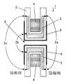
図1は本発明に係る圧力勾配型プラズマ発生装置の中間電極構造の第一実施形態を示す断面図であり、全体の真空成膜装置(例えばイオンプレーティング装置)や圧力勾配型プラズマ発生装置の構成は従来例(図8)と同様であるのでここでの説明は省略する。
【0014】
本発明に係る圧力勾配型プラズマ発生装置の中間電極1は、中心部にプラズマビームを収束し通過させる貫通口(オリフィス)3を有するドーナッツ形状をし、内部が中空構造となっているケース2に、プラズマビームを収束させてオリフィス3の中を通過させるための磁石4が支持固定されている。このとき、ケース2は、外形に沿った略円形の3つのシール部2a、2b、2cで溶接接合されることで、ケース2の内部を中空構造としている。なお、上記シール部2a、2b、2cは溶接接合のほか、Oリングやパッキンを挟んでネジ止めしたものでも良い。
【0015】
そして、このケース2の中空内を冷却溶媒5が流通するようになっている。この冷却溶媒5は、放電電子もしくはイオン衝撃または陰極からの熱などによってケース2が破壊されることを防ぐために中間電極1全体を冷却するためのものであり、後で説明するように中間電極1の中空内を流通するようになっている。
【0016】
以上の点については従来例と同様であるが、本発明ではケース2の側面が外周面に沿って窪んだ形状をしており、その窪みに磁石4が嵌め込まれた構成となっている。即ち、図2(a)に示すように環状の磁石4を、(b)に示すように4aと4bの2分割にし、(c)に示すようにケース2の側面から窪みに嵌め込んで固定している。なお、磁石4の代わりにコイルを用いた場合は、図3に示すようにケース2側面の窪みに薄い絶縁シート等を敷いてその上から絶縁皮膜付きの銅線を巻くことでコイル4cが設けられている。
【0017】
上記構成とすることで、従来はケース2内に収容され冷却溶媒5中に置かれていた磁石4もしくはコイルをケース2の外(冷却溶媒5の流路の外)に取り出し、冷却溶媒5による磁石4の劣化やコイル配線の断線防止が図れる。
【0018】
次に冷却溶媒5の流路について図4に沿って説明する。ケース2の側面の磁石4もしくはコイルが嵌め込まれる窪み以外の箇所にはケース2の中空内に通じる配管用の2つの穴が開けられ、その穴に配管5a、5bが取り付けられている。そして、まず、(a)に示すように配管5aから冷却溶媒5が流入され、▲1▼の矢印の方向に流れる。そして、ケースの中空内に形成された仕切壁2d、2eによってオリフィス3近傍に流れ込み、(b)に示すようにオリフィス3に沿って▲2▼の方向に流れて、磁石4を挟んだ反対側に流れ込む。そして、(c)に示すように仕切壁2f、2gに沿って▲3▼の方向に流れ、(d)に示すようにオリフィス3に沿って▲4▼の方向に流れて、(a)に示すように仕切壁2d、2eに沿って▲5▼の方向に流れ、配管5bから流出されるようになっている。こうして、ケース2の中空内を冷却溶媒5がムラなく循環し、特に中間電極1の中で最も熱を持つオリフィス3の近傍に沿って冷却溶媒5の流路を形成し、中間電極1全体を均等に冷却してプラズマ発生時の熱から保護するようになっている。なお、図1において6は、中間電極1のオリフィス3近傍が直接プラズマビームに接することないように覆っているカバーであり、タングステンなどのスパッタ率の低い金属やカーボン等で成っている。
【0019】
ここで、中間電極1のケース2のシール部2a、2b、2cは、中間電極1内に冷却溶媒5の流路となる中空構造を形成するために外形に沿った略円形のものであるが、従来のようにケースの中空内に磁石やコイルを保持する構造を有する必要がないため、オリフィス3から離れた位置とすることが可能となる。つまり、プラズマビームの収束部分となり熱が集中してしまうオリフィス3近傍からシール部2a、2b、2cを離すことで、シール部の破壊を防ぐことができる。
【0020】
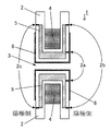
なお、シール部2a、2b、2cは、図1に示す第一実施形態のほかに、例えば図5乃至図7に示す第二実施形態乃至第四実施形態であっても良い。特に、図6に示す第三実施形態では、シール部を中間電極1の陽極側の2a、2bの2箇所のみとし、中空構造を変更したものであり、陰極側にシール部を形成していないことで、陰極からの熱などの影響を防げる構造となっている。また、図7に示す第四実施形態も同じく、シール部2a、2bを2箇所のみとし、これらシール部2a、2bを中間電極1の側面に形成したものであり、シール部2a、2bがオリフィス3から最も離れた位置であるため、シール部の保護の点でより効果が発揮されるものである。また、これら図6および図7は、シール部が2箇所のみであるため製造コスト削減にも効果がある。
【0021】
なお、上記実施形態で述べた配管5a、5bの位置および冷却溶媒5の流路はあくまでも一例であり、中間電極1内を冷却溶媒5が循環できる構造であれば良い。
【0022】
また、上記実施形態はいずれも圧力勾配型プラズマ発生装置の中間電極構造に関するものであり、従来例と同様に本中間電極構造を有する圧力勾配型プラズマ発生装置を用いた様々な構成のイオンプレーティング装置やプラズマCVD装置などの真空成膜装置に適用可能であることは言うまでもない。
【0023】
【発明の効果】
以上説明したように本発明によれば、圧力勾配型プラズマ発生装置の中間電極のケース側面が外周に沿って窪んでおり、その窪みにプラズマビームを収束させて貫通口を通過させるための環状の磁石もしくはコイルが嵌め込まれた構造としたことで、従来はケース内に収容され冷却溶媒中に置かれていた磁石もしくはコイルをケースの外(冷却溶媒の流路の外)に取り出し、冷却溶媒による磁石の劣化やコイル配線の断線防止が図れるといった効果を奏するものである。また、ケースの中空内を冷却溶媒がムラなく循環し、特に中間電極の中で最も熱を持つオリフィス近傍に沿って冷却溶媒の流路を形成したため、従来のような冷却溶媒の滞りがなくなって、中間電極全体が均等に冷却されるといった効果を奏するものである。さらに、中間電極のケースのシール部は、中間電極内に冷却溶媒の流路となる中空構造をつくるために外形に沿った略円形のものであるが、従来のようにケースの中空内に磁石やコイルを保持する構造を有する必要がないため、オリフィスから離れた位置とすることが可能となり、プラズマビームの収束部分となって熱が集中してしまうオリフィス近傍からシール部を離すことで、シール部の破壊を防ぐことができるといった効果をも奏するものである。
【図面の簡単な説明】
【図1】本発明に係る圧力勾配型プラズマ発生装置の中間電極構造の第一実施形態を示す断面図である。
【図2】本発明に係る圧力勾配型プラズマ発生装置の中間電極構造として磁石を用いた例を説明する説明図である。
【図3】本発明に係る圧力勾配型プラズマ発生装置の中間電極構造としてコイルを用いた例を示す断面図である。
【図4】本発明に係る中間電極内の冷却溶媒の流れを説明する説明図である。
【図5】本発明に係る圧力勾配型プラズマ発生装置の中間電極の第二実施形態を示す断面図である。
【図6】本発明に係る圧力勾配型プラズマ発生装置の中間電極の第三実施形態を示す断面図である。
【図7】本発明に係る圧力勾配型プラズマ発生装置の中間電極の第四実施形態を示す断面図である。
【図8】従来例におけるイオンプレーティング装置の一例を示す断面図である。
【図9】従来例における圧力勾配型プラズマ発生装置の中間電極構造を示す説明図であり、(a)は正面図、(b)は側面図、(c)は縦断面図である。
【図10】従来例における中間電極内の冷却溶媒の流れを説明する説明図であり、(a)は垂直断面図、(b)は水平断面図である。
【符号の説明】
1……中間電極
2……ケース
2a,2b,2c……シール部
2d,2e,2f,2g……仕切壁
3……貫通口(オリフィス)
4……磁石
4a,4b……分割磁石
4c……コイル
5……冷却溶媒
5a,5b……冷却溶媒用配管
6……カバー[0001]
BACKGROUND OF THE INVENTION
The present invention relates to an intermediate electrode structure of a pressure gradient type plasma generator used in a vacuum film forming apparatus.
[0002]
[Prior art]
Conventionally, for example, an
[0003]
Inside the
[0004]
The pressure
[0005]
When the carrier gas is introduced from the
[0006]
FIG. 9 is an explanatory diagram showing the first
[0007]
Hereinafter, the configuration of the first
[0008]
A
[0009]
The structure of the first
[0010]
[Problems to be solved by the invention]
However, the structure of the
[0011]
[Means for Solving the Problems]
As a specific means for solving the above-described conventional problems, the present invention includes a case having a through-hole in the center and a hollow inside, and a plasma beam fixed to the case to converge on the through-hole. An intermediate electrode structure of a pressure gradient type plasma generator comprising: an annular magnet or coil for passing through; and a cooling solvent for circulating the inside of the case to cool the whole. The present invention solves the problem by providing an intermediate electrode structure of a pressure gradient type plasma generator characterized by having a structure in which the magnet or coil is fitted in the recess. .
[0012]
DETAILED DESCRIPTION OF THE INVENTION
Next, the present invention will be described in detail based on embodiments shown in the drawings.
[0013]
FIG. 1 is a cross-sectional view showing a first embodiment of an intermediate electrode structure of a pressure gradient type plasma generating apparatus according to the present invention. The entire vacuum film forming apparatus (for example, ion plating apparatus) and pressure gradient type plasma generating apparatus Since the configuration is the same as that of the conventional example (FIG. 8), description thereof is omitted here.
[0014]
The intermediate electrode 1 of the pressure gradient type plasma generator according to the present invention has a donut shape having a through-hole (orifice) 3 for converging and passing a plasma beam at the center, and a
[0015]
And the cooling solvent 5 distribute | circulates the hollow inside of this
[0016]
Although the above points are the same as those of the conventional example, in the present invention, the side surface of the
[0017]
By adopting the above configuration, the
[0018]
Next, the flow path of the cooling solvent 5 will be described with reference to FIG. Two holes for piping that lead into the hollow of the
[0019]
Here, the
[0020]
In addition to the first embodiment shown in FIG. 1, the
[0021]
Note that the positions of the
[0022]
The above embodiments all relate to the intermediate electrode structure of the pressure gradient type plasma generator, and the ion plating of various configurations using the pressure gradient type plasma generator having this intermediate electrode structure as in the conventional example. Needless to say, the present invention can be applied to a vacuum film forming apparatus such as an apparatus or a plasma CVD apparatus.
[0023]
【The invention's effect】
As described above, according to the present invention, the case side surface of the intermediate electrode of the pressure gradient type plasma generator is recessed along the outer periphery, and the annular shape for converging the plasma beam to pass through the through hole in the recess. By adopting a structure in which a magnet or coil is fitted, the magnet or coil that has been housed in the case and placed in the cooling solvent in the past is taken out of the case (outside the cooling solvent flow path) This is effective in preventing deterioration of the magnet and disconnection of the coil wiring. In addition, the cooling solvent circulates evenly in the hollow of the case, and the cooling solvent flow path is formed along the vicinity of the orifice that has the most heat in the intermediate electrode. The entire intermediate electrode is uniformly cooled. Furthermore, the seal part of the case of the intermediate electrode has a substantially circular shape along the outer shape in order to create a hollow structure that serves as a flow path for the cooling solvent in the intermediate electrode. Since it is not necessary to have a structure for holding the coil and the coil, it can be located away from the orifice, and the seal portion is separated from the vicinity of the orifice where the heat concentrates as the converging portion of the plasma beam. There is also an effect that the destruction of the part can be prevented.
[Brief description of the drawings]
FIG. 1 is a cross-sectional view showing a first embodiment of an intermediate electrode structure of a pressure gradient plasma generating apparatus according to the present invention.
FIG. 2 is an explanatory view illustrating an example in which a magnet is used as an intermediate electrode structure of a pressure gradient type plasma generating apparatus according to the present invention.
FIG. 3 is a cross-sectional view showing an example in which a coil is used as an intermediate electrode structure of a pressure gradient plasma generating apparatus according to the present invention.
FIG. 4 is an explanatory diagram illustrating a flow of a cooling solvent in the intermediate electrode according to the present invention.
FIG. 5 is a cross-sectional view showing a second embodiment of the intermediate electrode of the pressure gradient plasma generating apparatus according to the present invention.
FIG. 6 is a cross-sectional view showing a third embodiment of an intermediate electrode of the pressure gradient type plasma generating apparatus according to the present invention.
FIG. 7 is a cross-sectional view showing a fourth embodiment of the intermediate electrode of the pressure gradient plasma generating apparatus according to the present invention.
FIG. 8 is a cross-sectional view showing an example of an ion plating apparatus in a conventional example.
FIG. 9 is an explanatory view showing an intermediate electrode structure of a pressure gradient type plasma generator in a conventional example, where (a) is a front view, (b) is a side view, and (c) is a longitudinal sectional view.
10A and 10B are explanatory diagrams for explaining the flow of a cooling solvent in an intermediate electrode in a conventional example, where FIG. 10A is a vertical sectional view and FIG. 10B is a horizontal sectional view.
[Explanation of symbols]
DESCRIPTION OF SYMBOLS 1 ...
4 ...
Claims (1)
前記ケースは側面が外周に沿って窪んでおり、その窪みに前記磁石もしくはコイルが嵌め込まれた構造となっていて、
更に、前記ケースの内部に中空を形成するためのシール部を、前記ケース側面の外周に沿って形成したことを特徴とする圧力勾配型プラズマ発生装置の中間電極構造。A case having a through-hole in the center and a hollow inside, an annular magnet or coil fixed to the case for converging and passing the plasma beam to the through-hole, and circulating in the hollow of the case Then, in the intermediate electrode structure of the pressure gradient type plasma generator comprising a cooling solvent for cooling the whole,
The case has a structure in which the side surface is recessed along the outer periphery, and the magnet or coil is fitted in the recess .
Furthermore, the intermediate electrode structure of the pressure gradient type plasma generator characterized by forming the seal part for forming a hollow inside the said case along the outer periphery of the said case side surface .
Priority Applications (1)
| Application Number | Priority Date | Filing Date | Title |
|---|---|---|---|
| JP2001071320A JP3832568B2 (en) | 2001-03-14 | 2001-03-14 | Intermediate electrode structure of pressure gradient plasma generator |
Applications Claiming Priority (1)
| Application Number | Priority Date | Filing Date | Title |
|---|---|---|---|
| JP2001071320A JP3832568B2 (en) | 2001-03-14 | 2001-03-14 | Intermediate electrode structure of pressure gradient plasma generator |
Publications (2)
| Publication Number | Publication Date |
|---|---|
| JP2002270395A JP2002270395A (en) | 2002-09-20 |
| JP3832568B2 true JP3832568B2 (en) | 2006-10-11 |
Family
ID=18929060
Family Applications (1)
| Application Number | Title | Priority Date | Filing Date |
|---|---|---|---|
| JP2001071320A Expired - Fee Related JP3832568B2 (en) | 2001-03-14 | 2001-03-14 | Intermediate electrode structure of pressure gradient plasma generator |
Country Status (1)
| Country | Link |
|---|---|
| JP (1) | JP3832568B2 (en) |
Families Citing this family (4)
| Publication number | Priority date | Publication date | Assignee | Title |
|---|---|---|---|---|
| JP4906448B2 (en) * | 2006-09-11 | 2012-03-28 | 新明和工業株式会社 | Intermediate electrode unit of plasma gun and plasma gun including the same |
| WO2008032523A1 (en) * | 2006-09-11 | 2008-03-20 | Shinmaywa Industries, Ltd. | Pressure gradient plasma gun |
| JP5096539B2 (en) * | 2010-09-02 | 2012-12-12 | 株式会社ニクニ | Plasma gun |
| JP2012199017A (en) * | 2011-03-18 | 2012-10-18 | Stanley Electric Co Ltd | Pressure gradient plasma generating device and deposition device using the same |
-
2001
- 2001-03-14 JP JP2001071320A patent/JP3832568B2/en not_active Expired - Fee Related
Also Published As
| Publication number | Publication date |
|---|---|
| JP2002270395A (en) | 2002-09-20 |
Similar Documents
| Publication | Publication Date | Title |
|---|---|---|
| KR890004172B1 (en) | Vacuum sputtering device | |
| JP4498366B2 (en) | Ion source cooled by fluid | |
| TWI287048B (en) | Equipment for cathode-sputtering | |
| JP2007505997A5 (en) | ||
| US6881311B2 (en) | Facing-targets-type sputtering apparatus | |
| US20130113169A1 (en) | Power input device and vacuum processing apparatus using the same | |
| US6160350A (en) | Ion plating apparatus | |
| JPH04297570A (en) | Cathode device having uniform burning characteristic and large surface | |
| JP2009149973A (en) | Sputtering apparatus and sputtering method | |
| JP3832568B2 (en) | Intermediate electrode structure of pressure gradient plasma generator | |
| KR20080100188A (en) | Ion source with removable anode assembly | |
| JP3917348B2 (en) | Arc evaporation source, vacuum deposition apparatus and vacuum deposition method | |
| JP5950866B2 (en) | Film forming apparatus and film forming method | |
| GB2110719A (en) | Sputtering apparatus | |
| US9368331B2 (en) | Sputtering apparatus | |
| JPS60255974A (en) | Sputter coating source with plural target rings | |
| JP3411312B2 (en) | Magnetron sputter cathode and method of adjusting film thickness distribution | |
| US6259102B1 (en) | Direct current gas-discharge ion-beam source with quadrupole magnetic separating system | |
| JP5096539B2 (en) | Plasma gun | |
| JP3156176B2 (en) | Vacuum deposition equipment | |
| JP3030420B2 (en) | Ion plating equipment | |
| JPWO2019167438A1 (en) | Magnetron Sputtering Cathode and Magnetron Sputtering Equipment Using It | |
| JP4074370B2 (en) | Vacuum deposition system | |
| JPS6354789B2 (en) | ||
| KR102492597B1 (en) | Sputtering assembly applied to PVD coating method and system including the same |
Legal Events
| Date | Code | Title | Description |
|---|---|---|---|
| A621 | Written request for application examination |
Free format text: JAPANESE INTERMEDIATE CODE: A621 Effective date: 20040624 |
|
| A977 | Report on retrieval |
Free format text: JAPANESE INTERMEDIATE CODE: A971007 Effective date: 20060213 |
|
| A131 | Notification of reasons for refusal |
Free format text: JAPANESE INTERMEDIATE CODE: A131 Effective date: 20060307 |
|
| A521 | Written amendment |
Free format text: JAPANESE INTERMEDIATE CODE: A523 Effective date: 20060428 |
|
| TRDD | Decision of grant or rejection written | ||
| A01 | Written decision to grant a patent or to grant a registration (utility model) |
Free format text: JAPANESE INTERMEDIATE CODE: A01 Effective date: 20060613 |
|
| A61 | First payment of annual fees (during grant procedure) |
Free format text: JAPANESE INTERMEDIATE CODE: A61 Effective date: 20060711 |
|
| R150 | Certificate of patent or registration of utility model |
Free format text: JAPANESE INTERMEDIATE CODE: R150 Ref document number: 3832568 Country of ref document: JP Free format text: JAPANESE INTERMEDIATE CODE: R150 |
|
| FPAY | Renewal fee payment (event date is renewal date of database) |
Free format text: PAYMENT UNTIL: 20090728 Year of fee payment: 3 |
|
| FPAY | Renewal fee payment (event date is renewal date of database) |
Free format text: PAYMENT UNTIL: 20100728 Year of fee payment: 4 |
|
| R250 | Receipt of annual fees |
Free format text: JAPANESE INTERMEDIATE CODE: R250 |
|
| FPAY | Renewal fee payment (event date is renewal date of database) |
Free format text: PAYMENT UNTIL: 20110728 Year of fee payment: 5 |
|
| R250 | Receipt of annual fees |
Free format text: JAPANESE INTERMEDIATE CODE: R250 |
|
| FPAY | Renewal fee payment (event date is renewal date of database) |
Free format text: PAYMENT UNTIL: 20110728 Year of fee payment: 5 |
|
| FPAY | Renewal fee payment (event date is renewal date of database) |
Free format text: PAYMENT UNTIL: 20120728 Year of fee payment: 6 |
|
| R250 | Receipt of annual fees |
Free format text: JAPANESE INTERMEDIATE CODE: R250 |
|
| FPAY | Renewal fee payment (event date is renewal date of database) |
Free format text: PAYMENT UNTIL: 20120728 Year of fee payment: 6 |
|
| FPAY | Renewal fee payment (event date is renewal date of database) |
Free format text: PAYMENT UNTIL: 20130728 Year of fee payment: 7 |
|
| R250 | Receipt of annual fees |
Free format text: JAPANESE INTERMEDIATE CODE: R250 |
|
| R250 | Receipt of annual fees |
Free format text: JAPANESE INTERMEDIATE CODE: R250 |
|
| R250 | Receipt of annual fees |
Free format text: JAPANESE INTERMEDIATE CODE: R250 |
|
| R250 | Receipt of annual fees |
Free format text: JAPANESE INTERMEDIATE CODE: R250 |
|
| R250 | Receipt of annual fees |
Free format text: JAPANESE INTERMEDIATE CODE: R250 |
|
| R250 | Receipt of annual fees |
Free format text: JAPANESE INTERMEDIATE CODE: R250 |
|
| R250 | Receipt of annual fees |
Free format text: JAPANESE INTERMEDIATE CODE: R250 |
|
| R250 | Receipt of annual fees |
Free format text: JAPANESE INTERMEDIATE CODE: R250 |
|
| LAPS | Cancellation because of no payment of annual fees |