JP3832523B2 - Pavement sheet - Google Patents
Pavement sheet Download PDFInfo
- Publication number
- JP3832523B2 JP3832523B2 JP09676597A JP9676597A JP3832523B2 JP 3832523 B2 JP3832523 B2 JP 3832523B2 JP 09676597 A JP09676597 A JP 09676597A JP 9676597 A JP9676597 A JP 9676597A JP 3832523 B2 JP3832523 B2 JP 3832523B2
- Authority
- JP
- Japan
- Prior art keywords
- sheet
- pavement
- base material
- material layer
- sliding
- Prior art date
- Legal status (The legal status is an assumption and is not a legal conclusion. Google has not performed a legal analysis and makes no representation as to the accuracy of the status listed.)
- Expired - Lifetime
Links
Images


Description
【0001】
【発明の属する技術分野】
本発明は、高速道路、一般道路等の橋梁部分において、橋体と舗装との間に敷設される舗装下地用シートに係り、特に橋体と舗装との相対移動を許容するための舗装下地用シートに関する。
【0002】
【従来の技術】
一般に、道路橋では橋体の上にアスファルト混合物による舗装が敷設されるが、このアスファルト混合物の下側に、橋体との相対移動を許容するための舗装下地用シートが介挿されることがある。この舗装下地用シートは、舗装と橋体との間で滑動を生じさせるものであり、例えば、橋の床版に目地等がある場合に、舗装にリフレクションクラックが発生するのを防止するために用いられる。また、例えば特公平3−26724号公報に記載されるように、橋桁と橋台との間又は橋桁と橋桁との間の伸縮遊間の両側にわたって舗装を連続して敷設する連続舗装工法では、伸縮遊間の両側の所定範囲に上記舗装下地用シートが用いられる。
【0003】
この橋面の連続舗装工法は、橋体上に、金属の薄板又は合成樹脂のフイルム等からなる摺動材を備えた舗装下地用シートを、伸縮遊間の両側にわたって敷設し、その上に引張力に対する補強用の応力伝達部材を埋設したアスファルト混合物を積層して舗装体を形成する。
【0004】
このような方法によって、橋桁と橋台との間又は橋桁と橋桁との間の伸縮遊間付近の舗装が施工されていると、舗装下地用シートの摺動材が水平方向の滑面となり、これを境に橋体と舗装とが滑動可能となる。したがって桁が伸縮し遊間が変化した時に、遊間上の舗装体が遊間の変化と同じ量の変形を生じるのではなく、伸縮遊間の両側の舗装体が橋体上で滑動し、所定の範囲にひずみが分散される。
つまり、図5に示すように、橋桁101,101が短縮し、伸縮遊間104が広くなった時にも、舗装体102は伸縮遊間上の部分のみが変形するのではなく、舗装下地用シートが敷設された範囲Lで滑動し、桁長の変化量をこの舗装下地用シートが敷設された範囲Lの舗装体で吸収することになる。したがって舗装体102には極部的に過大な変形や応力が発生せず、伸縮遊間の両側に亘って連続して舗装体を形成しても平坦で耐久性のある走行面を維持することができるものである。なお、図5中の符号103は、舗装体中に埋設された応力伝達部材を示すものである。
【0005】
上記のような用途に用いられる舗装下地用シートには、図6に示すように上側シート105と下側シート106とがあり、一般にはこれらが重ねて橋体101の上に敷設され、その上に舗装体102が設けられる。上側シート105は、図7に示すように金属箔、金属の薄板又は合成樹脂のフイルム等からなる摺動材111の上にゴムアスファルトコンパウンドからなる基材層112が形成され、そのうえに珪砂113が付着されている。そして、ゴムアスファルトコンパウンドからなる基材層112の中に引張力に抵抗するための網状部材(図示せず)が埋め込まれている。
【0006】
一方、下側シート106は金属箔、金属の薄板又は合成樹脂のフイルム等からなる下側の摺動材121とその下側に接着されたアスファルトコンパウンドからなる基材層122とで構成され、この基材層122が橋体101の上に圧接される。
【0007】
このような舗装下地用シートは工場製作され、ロール状に巻いて現場に搬入されるが、上側シート105ではゴムアスファルトコンパウンド層の表面に付着された珪砂103によって、ロール状に巻き付けられたシートが互いに接着してしまわないようになっている。また、下側シート106ではゴムアスファルトコンパウンド層の下面に剥離紙が張り付けられた状態で現場に搬入され、この剥離紙を剥して橋体上に敷設する。そして、これらのシートは、摺動材111,121がゴムアスファルトコンパウンドからなる基材層112,122より片側の側縁部で張り出すように幅が広くなっており、橋体上の広い範囲に敷設するときに、この部分を重ね合わせて、隙間が生じないように敷設される。
図7(a)は、上側シート105がその側縁部を重ね合わせて敷設された部分を示す拡大断面図であり、図7(b)は、下側シート106がその側縁部を重ね合わせて敷設された部分を示す拡大断面図である。
【0008】
【発明が解決しようとする課題】
しかしながら、上記のような舗装下地シートでは、次にような問題点がある。舗装の施工は、上記舗装下地用シートを敷設し、そのうえに加熱・混練されたアスファルト混合物を敷き均す。そして、ローラ等によって転圧して完成する。このとき、高温のアスファルト混合物によって舗装下地用シートのゴムアスファルトコンパウンド層が溶融し、ローラ等の転圧荷重によって、図8にしめすようにシートの重ね合わせた部分から上側シートの摺動材111と下側シートの摺動材121との間に流出する。図8(a)は、上側シート105の継ぎ目部で、一方の上側シート105aから流動したゴムアスファルトコンパウンドAが他方の上側シート105bと下側シート106との間に流出した状態を示すものである。また、図8(b)は、下側シート106の継ぎ目部で、一方の下側シート106aから流出したゴムアスファルトコンパウンドBが他方の下側シート106bと上側シート105との間に流出した状態を示すものである。
このようなゴムアスファルトコンパウンドの流動により、上側シートの摺動材111と下側シートの摺動材121との間の摺動が阻害され、舗装下地用シートの本来の機能を失うことになる。
本発明は、上記のような問題点に鑑みてなされたものであり、その目的は、現場で簡単に敷設することができ、橋体と舗装との間の滑動を確実に生じさせる舗装下地用シートを提供することである。
【0009】
【課題を解決するための手段】
上記の問題を解決するために、請求項1に記載の発明は、 アスファルト混合物を主材料とする舗装体の下側に敷設される舗装下地用シートであって、 柔軟なアスファルト系材料からなり、所定幅で長尺の薄い帯状となった基材層と、
この基材層の一方の面に接着され、該基材層より広い幅を有するフイルム状の部材であって、少なくとも片側の側縁部が前記基材層より張り出すように接着された摺動材と、 柔軟に変形する耐熱性材料からなり、前記摺動材の、前記基材層と接着されていない側縁部付近に、前記基材層と並列するように接着された帯状部材、とを有する舗装下地用シートを提供するものである。
【0010】
上記基材層に用いられる柔軟なアスファルト系材料としては、アスファルト乳剤の他、これに合成ゴム等を混合したゴムアスファルトコンパウンド等を用いることができ、常温で流動することなく1mm〜3mm程度の厚さの層に形成することができ、ロール状に巻き取ることができる程度の柔軟性を有するものである。
上記フィルム状の部材は、例えば、金属の薄板又は箔、合成樹脂のフィルム等を用いることができる。また、例えばアルミニウムの箔に合成樹脂フイルムを貼り合せたもののように、上記部材を組み合わせて用いてもよい。
上記帯状部材は、舗装用の材料として用いられるアスファルト混合物が加熱溶融された状態における温度に耐え得る程度の耐熱性を有するものであり、フェルト、不織布、発泡合成樹脂等を用いることができる。
【0011】
このような舗装下地用シートでは、橋体の広い範囲に隙間なく敷設し、その上に舗装を施すことによって、橋体と舗装との間の相対移動が許容され、伸縮遊間や目地等の両側に渡って連続するように形成された舗装のひび割れを防止することができる。そして、シートの継ぎ目部の重ね合わされた部分で、摺動材の側縁部付近に接着された帯状部材が、上下に重なる摺動材の双方に圧接されるので、舗装体を形成するアスファルト混合物が高温状態で上載され、転圧された時に、基材層のゴムアスファルトコンパウンドが継ぎ目部から滑動面上に流出するのが防止される。
また、この帯状部材は柔軟に変形する材料からなり、重なり合った摺動材に多少の凹凸があっても、これに追従して隙間なく双方の摺動材に接触し、流動化したゴムアスファルトコンパウンドの流出を防止する。さらに、この帯状部材は耐熱性材料でできているので、高温となってもその機能を失うことはない。
【0012】
請求項2に記載の発明は、請求項1に記載の舗装下地用シートにおいて、 前記帯状部材の表面に接着剤が塗布され、その上に剥離紙が接着されているものとする。
【0013】
この舗装下地用シートでは、その側縁部を重ね合わせて広い範囲に敷設するときに、帯状部材の剥離紙を剥して、この部分を隣接するシートと重ね合わせることによって、重ね合わされた摺動材間の帯状部材が双方の摺動材に強く接着され、ゴムアスファルトコンパウンドの流出がより確実に防止される。
【0014】
【発明の実施の形態】
(第一の実施の形態)
以下、本発明の実施の形態を図に基づいて説明する。
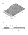
図1は、本発明の一実施形態である舗装下地用シートの概略構成を示す図であり、(a)図は、この舗装下地用シートの概略斜視図、(b)図は、(a)図中に示すa部の拡大断面図である。
この舗装下地用シートは、アスファルト混合物を主材料とする舗装体の下に敷設され、この舗装体と一体となって橋体上で滑動する上側シートであり、所定幅で帯状に形成され、図1(b)に示されるような層から構成される。すなわち、最下層にアルミニウムの薄板からなる摺動材が設けられ、その上にこの摺動材1よりも狭い幅の基材層2が接着されている。この基材層2の上面には、硅砂3が一様に散布・付着され、さらに基材層の層厚のほぼ中央に網状体5が埋め込まれている。また、上記摺動材の側縁部の前記基材層2が接着されていない部分に、帯状部材4が基材層2と並列するように接着されており、この帯状部材4の表面には接着剤が塗布され、その上に剥離紙6が貼着されている。
【0015】
上記摺動材1は、アルミニウムを薄く均一な板状としたものであり、下側シートの摺動材との間で滑動性を有するものである。
上記基材層2は、柔軟なゴムアスファルトコンパウンドを1mm〜3mm程度の薄層状に形成したものであり、上側に高温のアスファルト混合物が敷きならされ転圧されると、溶融してこの舗装体となるアスファルト混合物と一体となるものである。
上記基材層2内に埋設された網状体5は、ビニロン繊維製で線径が0.3〜0.5mm程度、網目の大きさが5mm程度のものを用いている。このような網状体5は、橋桁が伸縮した場合等、舗装体が橋体上で相対移動するときに、摩擦によって舗装体に発生する応力を分散させる効果を有し、舗装体の変形やひび割れ等を防止するものである。
【0016】
また、上記基材層2の表面に散布された硅砂3は、基材層2を形成するゴムアスファルトコンパウンドの粘着力を制限して取り扱いの便宜を図るとともに、この舗装下地用シートの上に加熱されたアスファルト混合物を積層し、舗装体を形成するときには、溶融したアスファルト混合物に取り込まれて、舗装体と舗装下地用シートの上側とを一体化する役割を有している。
上記帯状部材4は、基材層2とほぼ同じか又はこれより少し薄い層厚を有する耐熱性の不織布からなり、摺動材1上に接着されて、加熱された基材層のゴムアスファルトコンパウンドが流出するのを防止するものである。
【0017】
この舗装下地用シートは、工場において製作され、幅が約1mの長い帯状となっており、ロール状に巻いて現場に搬入される。現場では、下側シートの上に、摺動材1の滑動面が下側となるように敷設され、次いで帯状部材4上面の剥離紙6が取り除かれる。そして、この帯状部材4の上に隣接して敷設される他の舗装下地用シートの側縁部が重ね合わされ、この摺動材の下面と上記帯状部材の上面とが接着される。このような工程が繰り返して行なわれ、橋体上の所定の範囲に、舗装下地用シートが隙間なく敷き並べられる。
【0018】
次に、上記のような構成を有する舗装下地用シートの作用について説明する。
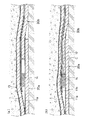
図2は、図1に示す舗装下地用シートの継ぎ目部の状態を示す概略断面図である。
隣接して敷設される2枚の舗装下地用シート10a,10bは、図2(a)に示すように第一のシート10aの帯状部材4を有する側縁部の上に第二のシート10bの帯状部材を有さない側縁部の底面が重ねられ、第一のシート10a上に接着されている帯状部材4の上面が、第二のシート10bの摺動材1bの下面と接着され、双方の摺動材が帯状部材を介して連続した状態となる。
【0019】
したがって、図2(a)のように重ねられたシートの上からアスファルト混合物の熱と転圧時の荷重とが加えられると、基材層2のゴムアスファルトコンパウンドが溶融して流動するが、この流動するゴムアスファルトコンパウンドは、図2(b)に示すように帯状部材4によってせき止められるため、摺動材が重ね合わされた継ぎ目部から流出するのが防止される。
【0020】
(第2の実施の形態)
上記舗装下地用シートは下面が滑動面となる上側シートであるが、これと組み合わせて用いられる下側シートについて以下に説明する。
図3は、この下側シートの構成を示す概略斜視図および一部拡大断面図である。
この下側シートは、図1に示す上側シートと同様に所定幅の帯状に形成されており、フィルム状の摺動材11の下側に、この摺動材11よりも狭い幅の基材層12が接着して形成されている。そして、工場等で製作された後現場に搬入される時には、この基材層12の下面に剥離紙13が接着されている。また、この下側シートの側縁部で、前記摺動材11に基材層12が接着されていない部分に、帯状部材14が基材層12と並列するように接着されており、この帯状部材14の下面に接着剤が塗布され、剥離紙15が貼着されている。
【0021】
上記摺動材11は、アルミニウムを薄い均一な板状に形成したものであり、上側シートの摺動材1との間で滑動するものである。
上記基材層12は、柔軟なゴムアスファルトコンパウンドを薄層状に形成したものであり、この下側シートを橋体上に敷設する場合、このゴムアスファルトコンパウンドの変形によって橋体の上面に密着させることができる。この下側シートの保存中や輸送時には、基材が他のものに接着するのを防止し、取り扱いを容易にするため、基材層12の表面に剥離紙13が貼着されている。
上記帯状部材14は、耐熱性を有する不織布からなり、基材層12とほぼ同じ層厚又はこれよりやや薄いものが用いられ、摺動材11の下面に接着されている。
【0022】
この下側シートは工場において基材層の厚さが1mm〜3mm、幅1mの帯状に形成され、ロール状に巻いて現場に搬入される。現場では、搬入された下側シートの剥離紙13を剥してその面を橋体の上面に押圧することによって、橋体上に容易に密着させることができる。先に敷設されたシートと隣接して敷設されるシートは、帯状部材14が接着された面を下側にし、この帯状部材が先に敷設されたシートの摺動材11上に重なるように配置され、帯状部材14を先に敷設したシートの摺動材11に接着する。このような工程を繰り返すことによって橋体上の所定の範囲に、上記下側シートが隙間なく敷き並べられる。
【0023】
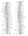
このように、下側シートが敷設されることによって、図4(a)に示すように、先に敷設された第一のシート20aの側縁部の上に第二のシート20bの帯状部材14を有する端部が重ねられ、帯状部材14の両面がそれぞれ、第1のシート20aの摺動材11aと第2のシート20bの摺動材11bとに接着され、重ね合わされた双方の摺動材の間を密閉することになる。したがって、舗装体を形成するために加熱されたアスファルト混合物が舗装下地用シート上に敷き均され転圧された時に、ゴムアスファルトコンパウンド層Cは高温となって流動するが、図4(b)に示すように、この帯状部材14でせき止められ、上側シート10の摺動材1と下側シート20の摺動材11aとの間に流出するのが防止される。このため、双方の摺動材1,11間の滑動性が維持され、橋桁の伸縮遊間や目地等が動いても、舗装体に作用する変形および応力が分散され、クラック等の発生が防止される。
【0024】
【発明の効果】
以上説明したように、本発明に係るの舗装下地用シートは、金属箔、金属の薄板又は合成樹脂のフィルム等からなる摺動材を有し、この摺動材が水平方向の滑動面となって橋体と舗装体との相対移動を許容するため、橋桁が伸縮し遊間が変化した場合や目地の両側が変位したときに、舗装体に生じるひずみがこの舗装下地用シートの敷設された範囲全体に分散される。したがって、伸縮遊間や目地等の両側にわたって連続した舗装体を形成しても、クラック等の発生を防止することができる。
【0025】
また、この舗装下地用シートでは、シートの側縁部の摺動材上に耐熱性材料からなる帯状部材が接着されており、この側縁部を重ね合わせて複数のシートを隙間なく敷き並べたときに、上記帯状部材が重ね合わされた双方のシートの摺動材に接着され、これらの間を密閉する。したがって、舗装下地用シートの上に舗装体を形成するアスファルト混合物が加熱された状態で敷きならされ、転圧されても、ゴムアスファルトコンパウンド層が摺動材の表面に流出することがなく、舗装下地シートによる滑動性が確実に維持される。
【図面の簡単な説明】
【図1】本発明の一実施形態である舗装下地用シートの概略斜視図および一部拡大断面図である。
【図2】図1に示す舗装下地用シート(上側シート)の継ぎ目部の状態を示す拡大断面図である。
【図3】本発明の他の実施形態である舗装下地用シートの概略斜視図および拡大断面図である。
【図4】図3に示す舗装下地用シート(下側シート)の継ぎ目部の状態を示す拡大断面図である。
【図5】伸縮遊間の両側にわたり連続して舗装体を設けるときの構成を示す説明図である。
【図6】舗装下地用シートを用いた舗装体の構成の一例を示す概略断面図である。
【図7】従来の舗装下地用シートの継ぎ目部の状態を示す概略断面図である。
【図8】従来の舗装下地用シートの継ぎ目部における問題点を示す概略断面図である。
【符号の説明】
1,11 摺動材
2,12 基材層
3 硅砂
4,14 帯状部材
5 網状体
6,15 帯状部材の剥離紙
10 上側シート(舗装下地用シート)
13 剥離紙
20 下側シート(舗装下地用シート)
101 橋桁
102 舗装体
103 応力伝達部材
104 伸縮遊間
105 上側シート
106 下側シート
111,121 摺動材
112,122 基材層
113 珪砂[0001]
BACKGROUND OF THE INVENTION
The present invention relates to a pavement ground sheet laid between a bridge body and pavement in a bridge portion of an expressway, a general road, etc., and in particular for a pavement ground to allow relative movement between the bridge body and the pavement. Regarding the sheet.
[0002]
[Prior art]
In general, road bridges are constructed with a pavement made of an asphalt mixture on the bridge body, but a pavement base sheet for allowing relative movement with the bridge body may be inserted below the asphalt mixture. . This sheet for pavement foundation causes sliding between the pavement and the bridge body. For example, in order to prevent reflection cracks from occurring in the pavement when there are joints on the floor slab of the bridge. Used. In addition, as described in, for example, Japanese Patent Publication No. 3-26724, in a continuous pavement method in which pavement is continuously laid on both sides of a stretchable play between a bridge girder and an abutment or between a bridge girder and a bridge girder, The pavement sheet is used in a predetermined range on both sides of the sheet.
[0003]
In this continuous pavement method for bridge surfaces, a sheet for pavement foundation equipped with a sliding material made of a thin metal plate or synthetic resin film is laid on both sides of the stretchable play on the bridge body, and a tensile force is applied on it. A pavement is formed by laminating an asphalt mixture in which a stress transmission member for reinforcement is embedded.
[0004]
When a pavement is constructed between the bridge girder and the abutment or near the stretchable gap between the bridge girder and the bridge girder, the sliding material of the pavement base sheet becomes a horizontal smooth surface. The bridge body and pavement can slide on the border. Therefore, when the girders expand and contract and the gap changes, the pavement on the gap does not cause the same amount of deformation as the change between the gaps. Distortion is dispersed.
That is, as shown in FIG. 5, when the
[0005]
As shown in FIG. 6, the pavement base sheet used for the above-described uses includes an
[0006]
On the other hand, the
[0007]
Such a pavement base sheet is manufactured in a factory, rolled into a roll, and carried to the site. In the
FIG. 7A is an enlarged cross-sectional view showing a portion where the
[0008]
[Problems to be solved by the invention]
However, the pavement base sheet as described above has the following problems. For pavement construction, the above-mentioned sheet for pavement foundation is laid, and the asphalt mixture heated and kneaded is laid on the sheet. Then, it is completed by rolling with a roller or the like. At this time, the rubber asphalt compound layer of the paving foundation sheet is melted by the high-temperature asphalt mixture, and the upper
By such a flow of the rubber asphalt compound, sliding between the
The present invention has been made in view of the problems as described above, and the purpose thereof is for pavement foundations that can be easily laid on the spot and reliably cause sliding between the bridge body and the pavement. Is to provide a sheet.
[0009]
[Means for Solving the Problems]
In order to solve the above problem, the invention described in
A sliding member bonded to one surface of the base material layer and having a wider width than the base material layer so that at least one side edge projects from the base material layer. A belt-shaped member that is made of a heat-resistant material that is flexibly deformed, and that is bonded so as to be parallel to the base material layer in the vicinity of a side edge of the sliding material that is not bonded to the base material layer; The sheet | seat for pavement base | substrates which has this is provided.
[0010]
As a flexible asphalt material used for the base material layer, a rubber asphalt compound mixed with a synthetic rubber or the like can be used in addition to an asphalt emulsion, and the thickness is about 1 mm to 3 mm without flowing at room temperature. It can be formed in a layer having a degree of flexibility that can be wound into a roll.
As the film-like member, for example, a metal thin plate or foil, a synthetic resin film, or the like can be used. Moreover, you may use combining the said member like what bonded the synthetic resin film to the foil of aluminum, for example.
The band-shaped member has heat resistance enough to withstand the temperature in a state where the asphalt mixture used as a paving material is heated and melted, and felt, nonwoven fabric, foamed synthetic resin, or the like can be used.
[0011]
In such a sheet for pavement foundation, the relative movement between the bridge body and the pavement is allowed by laying on the wide area of the bridge body without any gaps, and paveing on it, both sides of the expansion and contraction play, joints, etc. It is possible to prevent cracking of the pavement formed so as to be continuous over the range. And, as the belt-like member adhered in the vicinity of the side edge of the sliding material at the overlapped portion of the seam portion of the sheet is pressed against both of the sliding material overlapping vertically, the asphalt mixture forming the pavement When the material is placed and rolled at a high temperature, the rubber asphalt compound of the base material layer is prevented from flowing out from the joint portion onto the sliding surface.
In addition, this belt-shaped member is made of a material that can be flexibly deformed, and even if there are some irregularities on the overlapping sliding material, it follows this and contacts both sliding materials without gaps, and fluidized rubber asphalt compound To prevent the outflow. Further, since the belt-like member is made of a heat-resistant material, its function is not lost even at a high temperature.
[0012]
The invention according to
[0013]
In this pavement base sheet, when the side edge portions are overlapped and laid in a wide range, the release material of the strip-shaped member is peeled off, and this portion is overlapped with the adjacent sheet, thereby overlapping the sliding material. The belt-like member in between is strongly bonded to both sliding members, and the outflow of the rubber asphalt compound is more reliably prevented.
[0014]
DETAILED DESCRIPTION OF THE INVENTION
(First embodiment)
Hereinafter, embodiments of the present invention will be described with reference to the drawings.
FIG. 1 is a diagram showing a schematic configuration of a pavement foundation sheet according to an embodiment of the present invention. FIG. 1A is a schematic perspective view of the pavement foundation sheet, and FIG. It is an expanded sectional view of a section shown in the figure.
This pavement base sheet is an upper sheet that is laid under a pavement made mainly of an asphalt mixture and slides on the bridge body integrally with this pavement, and is formed in a band shape with a predetermined width. It is composed of layers as shown in 1 (b). That is, a sliding material made of a thin aluminum plate is provided in the lowermost layer, and a
[0015]
The sliding
The
The net body 5 embedded in the
[0016]
Further, the silica sand 3 sprayed on the surface of the
The belt-
[0017]
This sheet for pavement foundation is manufactured in a factory, has a long band shape with a width of about 1 m, is wound in a roll shape, and is carried to the site. At the site, the sliding
[0018]
Next, the effect | action of the sheet | seat for pavement base | substrates which has the above structures is demonstrated.
FIG. 2 is a schematic cross-sectional view showing a state of a joint portion of the pavement foundation sheet shown in FIG.
As shown in FIG. 2 (a), two adjacent
[0019]
Therefore, when the heat of the asphalt mixture and the load at the time of rolling are applied from above the stacked sheets as shown in FIG. 2 (a), the rubber asphalt compound of the
[0020]
(Second Embodiment)
The pavement base sheet is an upper sheet whose lower surface is a sliding surface. The lower sheet used in combination with this will be described below.
FIG. 3 is a schematic perspective view and a partially enlarged sectional view showing the configuration of the lower sheet.
The lower sheet is formed in a band shape having a predetermined width in the same manner as the upper sheet shown in FIG. 1, and a base material layer having a narrower width than the sliding
[0021]
The sliding
The
The belt-
[0022]
The lower sheet is formed in a strip shape with a base layer thickness of 1 mm to 3 mm and a width of 1 m in a factory, and is wound into a roll and carried to the site. At the site, the
[0023]
Thus, by laying the lower sheet, as shown in FIG. 4A, the band-
[0024]
【The invention's effect】
As described above, the sheet for pavement foundation according to the present invention has a sliding material made of a metal foil, a metal thin plate, a synthetic resin film, or the like, and this sliding material becomes a horizontal sliding surface. In order to allow relative movement between the bridge body and the pavement, when the bridge girder expands and contracts and the play gap changes, or when both sides of the joint are displaced, the strain that occurs in the pavement is the area where the sheet for pavement foundation is laid Distributed throughout. Therefore, even if a continuous pavement is formed over both sides of the stretchable play and joints, the occurrence of cracks and the like can be prevented.
[0025]
Further, in this pavement base sheet, a belt-like member made of a heat-resistant material is bonded onto the sliding material on the side edge portion of the sheet, and a plurality of sheets are laid out without any gaps by overlapping the side edge portions. Sometimes, the belt-like member is bonded to the sliding material of both the stacked sheets, and the space between them is sealed. Therefore, even if the asphalt mixture forming the pavement is heated and spread on the pavement base sheet, the rubber asphalt compound layer does not flow out to the surface of the sliding material even if it is rolled. The sliding property by the base sheet is reliably maintained.
[Brief description of the drawings]
FIG. 1 is a schematic perspective view and a partially enlarged sectional view of a sheet for pavement foundation according to an embodiment of the present invention.
FIG. 2 is an enlarged cross-sectional view illustrating a state of a joint portion of the pavement foundation sheet (upper sheet) illustrated in FIG.
FIGS. 3A and 3B are a schematic perspective view and an enlarged cross-sectional view of a pavement base sheet according to another embodiment of the present invention. FIGS.
4 is an enlarged cross-sectional view showing a state of a joint portion of the pavement foundation sheet (lower sheet) shown in FIG. 3;
FIG. 5 is an explanatory diagram showing a configuration when a pavement is continuously provided across both sides of the stretchable play.
FIG. 6 is a schematic cross-sectional view showing an example of the configuration of a pavement using a pavement base sheet.
FIG. 7 is a schematic cross-sectional view showing a state of a joint portion of a conventional pavement base sheet.
FIG. 8 is a schematic cross-sectional view showing a problem in a joint portion of a conventional pavement base sheet.
[Explanation of symbols]
DESCRIPTION OF
13 Release paper 20 Lower sheet (Pavement sheet)
DESCRIPTION OF
Claims (2)
柔軟なアスファルト系材料からなり、所定幅で長尺の薄い帯状となった基材層と、
この基材層の一方の面に接着され、該基材層より広い幅を有するフイルム状の部材であって、少なくとも片側の側縁部が前記基材層より張り出すように接着された摺動材と、
柔軟に変形する耐熱性材料からなり、前記摺動材の、前記基材層と接着されていない側縁部付近に、前記基材層と並列するように接着された帯状部材、とを有することを特徴とする舗装下地用シート。It is a sheet for a pavement foundation laid on the lower side of a pavement made mainly of an asphalt mixture,
A base material layer made of a flexible asphalt material and having a long and thin strip shape with a predetermined width;
A sliding member bonded to one surface of the base material layer and having a wider width than the base material layer so that at least one side edge projects from the base material layer. Material,
A belt-like member made of a heat-resistant material that is deformed flexibly and bonded in the vicinity of a side edge portion of the sliding material that is not bonded to the base material layer so as to be parallel to the base material layer. A sheet for paving groundwork characterized by
Priority Applications (1)
| Application Number | Priority Date | Filing Date | Title |
|---|---|---|---|
| JP09676597A JP3832523B2 (en) | 1997-03-31 | 1997-03-31 | Pavement sheet |
Applications Claiming Priority (1)
| Application Number | Priority Date | Filing Date | Title |
|---|---|---|---|
| JP09676597A JP3832523B2 (en) | 1997-03-31 | 1997-03-31 | Pavement sheet |
Publications (2)
| Publication Number | Publication Date |
|---|---|
| JPH10280306A JPH10280306A (en) | 1998-10-20 |
| JP3832523B2 true JP3832523B2 (en) | 2006-10-11 |
Family
ID=14173740
Family Applications (1)
| Application Number | Title | Priority Date | Filing Date |
|---|---|---|---|
| JP09676597A Expired - Lifetime JP3832523B2 (en) | 1997-03-31 | 1997-03-31 | Pavement sheet |
Country Status (1)
| Country | Link |
|---|---|
| JP (1) | JP3832523B2 (en) |
Families Citing this family (2)
| Publication number | Priority date | Publication date | Assignee | Title |
|---|---|---|---|---|
| JP5549058B2 (en) * | 2008-07-02 | 2014-07-16 | 新日鐵住金株式会社 | Refractory joint construction method and refractory joint structure |
| CN116061455B (en) * | 2023-04-06 | 2023-06-23 | 喜跃发国际环保新材料股份有限公司 | Processing technology and processing system of net crack paste |
-
1997
- 1997-03-31 JP JP09676597A patent/JP3832523B2/en not_active Expired - Lifetime
Also Published As
| Publication number | Publication date |
|---|---|
| JPH10280306A (en) | 1998-10-20 |
Similar Documents
| Publication | Publication Date | Title |
|---|---|---|
| US7146771B2 (en) | Cap sheet, roofing installation, and method | |
| JP5496615B2 (en) | Waterproofing method, waterproof structure and fiber plate on top of concrete slab | |
| US4015302A (en) | Expansion joints | |
| JP3832523B2 (en) | Pavement sheet | |
| JP4188505B2 (en) | Asphalt sheet | |
| KR101137804B1 (en) | Waterproof seat and construction method thereof | |
| JP3506266B2 (en) | Pavement on bridge surface | |
| CA2487868C (en) | Surfacing structure for traffic areas and for surfaces of structures | |
| JP3137475B2 (en) | Pavement of bridge surface and continuous pavement method of bridge surface | |
| US3996401A (en) | Flat roofing laminate having means to arrest transmission of deformations from the bottom surface to the top surface | |
| JP4927681B2 (en) | Pavement structure | |
| JP4247071B2 (en) | Waterproofing method for floor slab and tack sheet material used therefor | |
| JP3739634B2 (en) | Water stop for road play | |
| JPH06346405A (en) | Pavement reinforcing method and reinforcing material | |
| KR100489730B1 (en) | Fiber mat for protection of fluid-applied membrane and waterproofing method using the same | |
| JP2590201Y2 (en) | Pavement base sheet | |
| JP2763455B2 (en) | Paved version | |
| JP2590191Y2 (en) | Pavement base sheet | |
| JP3544369B2 (en) | Road bridge joint structure | |
| JP4071324B2 (en) | Continuous pavement structure of bridge surface | |
| JP3580747B2 (en) | Curing waterproofing sheet for concrete and curing waterproofing method | |
| JPH1193104A (en) | Continuous paving structure of bridge face | |
| JPH0632961Y2 (en) | Road joint | |
| EP1262601B1 (en) | Bridging material for a joint construction as well as prefabricated bridging unit | |
| JP2024059355A (en) | Waterproof structure |
Legal Events
| Date | Code | Title | Description |
|---|---|---|---|
| A621 | Written request for application examination |
Free format text: JAPANESE INTERMEDIATE CODE: A621 Effective date: 20040217 |
|
| A977 | Report on retrieval |
Free format text: JAPANESE INTERMEDIATE CODE: A971007 Effective date: 20060529 |
|
| TRDD | Decision of grant or rejection written | ||
| A01 | Written decision to grant a patent or to grant a registration (utility model) |
Free format text: JAPANESE INTERMEDIATE CODE: A01 Effective date: 20060606 |
|
| A61 | First payment of annual fees (during grant procedure) |
Free format text: JAPANESE INTERMEDIATE CODE: A61 Effective date: 20060612 |
|
| A61 | First payment of annual fees (during grant procedure) |
Free format text: JAPANESE INTERMEDIATE CODE: A61 Effective date: 20060711 |
|
| R150 | Certificate of patent or registration of utility model |
Free format text: JAPANESE INTERMEDIATE CODE: R150 |
|
| FPAY | Renewal fee payment (event date is renewal date of database) |
Free format text: PAYMENT UNTIL: 20090728 Year of fee payment: 3 |
|
| FPAY | Renewal fee payment (event date is renewal date of database) |
Free format text: PAYMENT UNTIL: 20140728 Year of fee payment: 8 |
|
| R250 | Receipt of annual fees |
Free format text: JAPANESE INTERMEDIATE CODE: R250 |
|
| EXPY | Cancellation because of completion of term |