JP3832303B2 - Driving machine - Google Patents
Driving machine Download PDFInfo
- Publication number
- JP3832303B2 JP3832303B2 JP2001309979A JP2001309979A JP3832303B2 JP 3832303 B2 JP3832303 B2 JP 3832303B2 JP 2001309979 A JP2001309979 A JP 2001309979A JP 2001309979 A JP2001309979 A JP 2001309979A JP 3832303 B2 JP3832303 B2 JP 3832303B2
- Authority
- JP
- Japan
- Prior art keywords
- bumper
- piston
- driver blade
- driving machine
- stopper
- Prior art date
- Legal status (The legal status is an assumption and is not a legal conclusion. Google has not performed a legal analysis and makes no representation as to the accuracy of the status listed.)
- Expired - Fee Related
Links
Images


Classifications
-
- B—PERFORMING OPERATIONS; TRANSPORTING
- B25—HAND TOOLS; PORTABLE POWER-DRIVEN TOOLS; MANIPULATORS
- B25C—HAND-HELD NAILING OR STAPLING TOOLS; MANUALLY OPERATED PORTABLE STAPLING TOOLS
- B25C1/00—Hand-held nailing tools; Nail feeding devices
- B25C1/04—Hand-held nailing tools; Nail feeding devices operated by fluid pressure, e.g. by air pressure
- B25C1/047—Mechanical details
Landscapes
- Physics & Mathematics (AREA)
- Fluid Mechanics (AREA)
- Engineering & Computer Science (AREA)
- Mechanical Engineering (AREA)
- Portable Nailing Machines And Staplers (AREA)
Description
【0001】
【発明の属する技術分野】
本発明は打込機に関するもので、ピストンバンパの共用化を図るようにしたものである。
【0002】
【従来の技術】
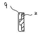
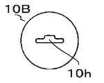
一般に打込機は図1に示すように、木材等の被打込材に止具を打込むためのドライバーブレード2と圧縮空気の力を受けるピストン3が設けられ、ドライバーブレード2とピストン3を下死点から上死点に復帰させるための空気を貯留した戻り室4を備えている。ドライバーブレード2とピストン3は一体に結合し、シリンダ部5内を往復動する。シリンダ部5には、戻り室4と連通する空気通路6を備えている。前記シリンダ部5の下側には、止具を打撃する際に駆動された前記ピストン3の下面を受けるために、ピストンバンパ7が配設されている。打込機1は、止具を打撃した後、前述のようにドライバーブレード2とピストン3を下死点から上死点に復帰させる必要があり、戻り室4に貯留された圧縮空気が、シリンダ部5に備えられた空気通路6を通り、ピストン3下面を押圧することにより、ピストン3を上死点まで復帰させる。ところが、前記ドライバーブレード2の形状は図2、4に示す一例のように、止具の種類により異なり、図7に示すように、前記ドライバーブレード2とノーズ部8射出口との嵌合において空隙9が構成され、前記ドライバーブレード2とピストン3が上死点へ復帰し始めた時に、前記空隙9を経由して戻り室4と、シリンダ部5に備えられた空気通路6と、シリンダ部5と、ピストン3下面と、ノーズ部8上面により形成された、前記ドライバーブレード2とピストン3を上死点まで復帰させるための蓄圧室が大気と連通し、その結果、圧力損失が発生し、前記ドライバーブレード2とピストン3が上死点まで復帰できないことがある。上記現象を防止するため、図8のように、ピストンバンパ7下部にドライバーブレード2の断面形状とほぼ同形状の窓が形成されたバンパシート10を圧入し、かつドライバーブレード2に嵌合させ、空隙9の面積を小さくすることにより圧力損失を防止し、ドライバーブレード2とピストン3を確実に上死点まで復帰させることが考えられた。
【0003】
【発明が解決しようとする課題】
しかしながら、バンパシート10の形状は、ドライバーブレード2の形状に依存するため、ドライバーブレード2の種類が多くなる分だけバンパシート10の種類も多くなっているのが現状である。従って、前記バンパシート10を圧入するピストンバンパ7も種類が増えてしまい、それらは、外径と厚さが異なっており、原価高の原因、部品共用化の妨げとなっている。
【0004】
本発明の目的は、上記した従来技術の欠点をなくし、ピストンバンパの共用化を図り安価な構成が可能となる打込機を提供することである。
【0005】
【課題を解決するための手段】
上記目的は、既存のバンパシートに合わせた段差を形成し、少なくとも2種類以上のバンパシートが圧入出来る形状の段差をピストンバンパ下部に設けることにより達成される。
【0006】
【発明の実施の形態】
本発明の一実施形態について図を用いて説明する。図1において、打込機1には、ドライバーブレード2、ピストン3、シリンダ部5、ノーズ8が配設されており、シリンダ部5下部には、バンパシート10を圧入したピストンバンパ7が配設されている。ノーズ部8には、送り機構により、止具が送り込まれるように構成されている。ドライバーブレード2とピストン3は、圧縮空気により駆動され、ノーズ8内の止具を打撃するとともに、ピストン3の下面は、ピストンバンパ7の上面に受け止められ、止具を打撃した時の衝撃は、ピストンバンパ7に吸収される。前記ピストンバンパ7は、図12、13に示す形状でその材質はゴム等の弾性体で構成され、ピストンバンパ7下部には、少なくとも2つ以上の形状および高さの異なる段差7A、7Bが形成されている。前記バンパシート10Bは、ピストンバンパ7下部の段差7Bに圧入することにより、半径方向の締め代を持ち、ピストンバンパ7下面とノーズ8上面にて押さえつけることで軸方向の動きを抑止している。前記バンパシート10には、ドライバーブレード2が嵌合出来るようドライバーブレード2の断面形状と同じ窓10hが形成されている。図14、15は各々図2、4に示すドライバーブレード2B、2Aに対応したバンパシート10B、10Aの一例であるが、ピストンバンパ7には、バンパシート10を圧入した時に合致するような段差7A、7Bを形成すれば、ピストンバンパ7下部の段差の形状および高さは、どのようなものでも良く、必ずしも断面形状が丸になる必要は無い。
【0007】
【発明の効果】
以上説明したように本発明によれば、ピストンバンパの段差を複数個の既存のバンパシートが圧入できる形状にしたのでピストンバンパの共用化を図ることができる。従って、ピストンバンパの種類を少なく共用化でき、安価な打込機を提供することが出来る。
【図面の簡単な説明】
【図1】本発明打込機の一実施形態を示す要部断面正面図。
【図2】ドライバーブレードの一例を示す側面図。
【図3】図2のA−A線断面図。
【図4】ドライバーブレードの他の例を示す要部断面側面図。
【図5】図4のB−B線断面図。
【図6】従来の技術を説明するための打込機の要部断面正面図。
【図7】図6矢視図。
【図8】従来の打込機の一例を示す要部断面正面図。
【図9】図8矢視図。
【図10】本発明の一実施形態を示し、図2のドライバーブレード2Bを具備した打込機の要部断面正面図。
【図11】本発明の一実施形態を示し、図4のドライバーブレード2Aを具備した打込機の要部断面正面図。
【図12】ピストンバンパの一実施形態を示す断面図。
【図13】図12の底面図。
【図14】図2のドライバーブレード2Bに対応するバンパシート10Bの上面図。
【図15】図4のドライバーブレード2Aに対応するバンパシート10Aの上面図。
【符号の説明】
1は打込機、2はドライバーブレード、7はピストンバンパ、8はノーズ、10はバンパシートである。[0001]
BACKGROUND OF THE INVENTION
The present invention relates to a driving machine, and is intended to share a piston bumper.
[0002]
[Prior art]
Generally in the driving machine as shown in FIG. 1, the
[0003]
[Problems to be solved by the invention]
However, the shape of the
[0004]
An object of the present invention is to provide a driving machine that eliminates the above-mentioned drawbacks of the prior art, enables the piston bumper to be shared, and enables an inexpensive configuration.
[0005]
[Means for Solving the Problems]
The above-described object is achieved by forming a step according to an existing bumper seat and providing a step having a shape capable of press-fitting at least two types of bumper seats under the piston bumper.
[0006]
DETAILED DESCRIPTION OF THE INVENTION
An embodiment of the present invention will be described with reference to the drawings. In FIG. 1, a
[0007]
【The invention's effect】
As described above, according to the present invention, since the step of the piston bumper is shaped so that a plurality of existing bumper seats can be press-fitted, the piston bumper can be shared. Therefore, the number of types of piston bumpers can be shared and an inexpensive driving machine can be provided.
[Brief description of the drawings]
FIG. 1 is a cross-sectional front view of an essential part showing an embodiment of a driving machine of the present invention.
Figure 2 is a side view showing an example of drivers blade.
3 is a cross-sectional view taken along line AA in FIG.
[4] fragmentary sectional side view showing another example of drivers blade.
5 is a cross-sectional view taken along line BB in FIG.
FIG. 6 is a cross-sectional front view of an essential part of a driving machine for explaining a conventional technique.
7 is a view as seen from the arrow of FIG.
FIG. 8 is a cross-sectional front view of an essential part showing an example of a conventional driving machine.
FIG. 9 is a view as seen from the arrow in FIG.
10 shows a cross-sectional front view of a main part of a driving machine including the
11 shows an embodiment of the present invention and is a cross-sectional front view of an essential part of a driving machine equipped with the
FIG. 12 is a cross-sectional view showing an embodiment of a piston bumper.
13 is a bottom view of FIG. 12. FIG.
14 is a top view of a
15 is a top view of a
[Explanation of symbols]
1 is a driving machine, 2 is a driver blade, 7 is a piston bumper, 8 is a nose, and 10 is a bumper seat.
Claims (1)
前記ピストンバンパ下部に、形状および高さの異なるバンパシート埋設用の段差を少なくとも2個形成し、ドライバブレードの断面形状と合致した形状の窓を有するバンパシートを何れかの段差に選択的に圧入してバンパシートを取り付けるようにしたことを特徴とする打込機。A magazine for storing the stopper, a nose portion for driving the stopper, a driver blade for striking the stopper, a piston integrated with the driver blade, a cylinder portion for slidably supporting the piston, and a lower portion of the cylinder portion A driving machine composed of a provided piston bumper and a bumper seat embedded under the piston bumper,
At least two bumper sheet embedding steps with different shapes and heights are formed in the lower part of the piston bumper, and a bumper sheet having a window shape that matches the cross-sectional shape of the driver blade is selectively press-fitted into any step. And a bumper seat .
Priority Applications (1)
| Application Number | Priority Date | Filing Date | Title |
|---|---|---|---|
| JP2001309979A JP3832303B2 (en) | 2001-10-05 | 2001-10-05 | Driving machine |
Applications Claiming Priority (1)
| Application Number | Priority Date | Filing Date | Title |
|---|---|---|---|
| JP2001309979A JP3832303B2 (en) | 2001-10-05 | 2001-10-05 | Driving machine |
Publications (3)
| Publication Number | Publication Date |
|---|---|
| JP2003117851A JP2003117851A (en) | 2003-04-23 |
| JP2003117851A5 JP2003117851A5 (en) | 2005-03-17 |
| JP3832303B2 true JP3832303B2 (en) | 2006-10-11 |
Family
ID=19129040
Family Applications (1)
| Application Number | Title | Priority Date | Filing Date |
|---|---|---|---|
| JP2001309979A Expired - Fee Related JP3832303B2 (en) | 2001-10-05 | 2001-10-05 | Driving machine |
Country Status (1)
| Country | Link |
|---|---|
| JP (1) | JP3832303B2 (en) |
Families Citing this family (1)
| Publication number | Priority date | Publication date | Assignee | Title |
|---|---|---|---|---|
| US10800022B2 (en) * | 2017-02-09 | 2020-10-13 | Illinois Tool Works Inc. | Powered-fastener-driving tool including a driver blade having a varying cross-section |
-
2001
- 2001-10-05 JP JP2001309979A patent/JP3832303B2/en not_active Expired - Fee Related
Also Published As
| Publication number | Publication date |
|---|---|
| JP2003117851A (en) | 2003-04-23 |
Similar Documents
| Publication | Publication Date | Title |
|---|---|---|
| US7980439B2 (en) | Nailing machine | |
| JP3818234B2 (en) | Nailer | |
| EP2269780B1 (en) | Driving tool and bumper of driving tool | |
| WO2005097423B1 (en) | Upper bumper configuration for a power tool | |
| JP3832303B2 (en) | Driving machine | |
| CN101956605B (en) | Mounting structure for engine cover | |
| US20100243286A1 (en) | Power tool and cushioning mechanism thereof | |
| US6318239B1 (en) | Nailer and bumper provided therein for braking impact piston | |
| JP2003117851A5 (en) | ||
| EP1616669B1 (en) | Fastener driving tool | |
| JP4111085B2 (en) | Nailer | |
| JP2776195B2 (en) | Driving machine | |
| JPH01170570U (en) | ||
| JPH0675680U (en) | Ignition tool blanking prevention device | |
| CN211663186U (en) | Automobile anti-collision strip | |
| JPH09300238A (en) | Driver blade of driving machine | |
| JP3948036B2 (en) | Stopper holding device for driving machine | |
| CN206797481U (en) | Front anticollision beam of automobile | |
| JP3595868B2 (en) | Driving machine | |
| JPS5917586Y2 (en) | Bumper destruction prevention device for impact tools | |
| JP4174727B2 (en) | Nailer | |
| JPH0435882U (en) | ||
| JPH0616663Y2 (en) | Driving machine | |
| JP3045050U (en) | Nail feeding mechanism for nailing machine | |
| JPH07672U (en) | Fixing tool striking tool |
Legal Events
| Date | Code | Title | Description |
|---|---|---|---|
| A521 | Written amendment |
Free format text: JAPANESE INTERMEDIATE CODE: A523 Effective date: 20040423 |
|
| A621 | Written request for application examination |
Free format text: JAPANESE INTERMEDIATE CODE: A621 Effective date: 20040423 |
|
| A977 | Report on retrieval |
Free format text: JAPANESE INTERMEDIATE CODE: A971007 Effective date: 20050929 |
|
| A131 | Notification of reasons for refusal |
Free format text: JAPANESE INTERMEDIATE CODE: A131 Effective date: 20051101 |
|
| A521 | Written amendment |
Free format text: JAPANESE INTERMEDIATE CODE: A523 Effective date: 20051209 |
|
| TRDD | Decision of grant or rejection written | ||
| A01 | Written decision to grant a patent or to grant a registration (utility model) |
Free format text: JAPANESE INTERMEDIATE CODE: A01 Effective date: 20060627 |
|
| A61 | First payment of annual fees (during grant procedure) |
Free format text: JAPANESE INTERMEDIATE CODE: A61 Effective date: 20060710 |
|
| R150 | Certificate of patent or registration of utility model |
Free format text: JAPANESE INTERMEDIATE CODE: R150 Ref document number: 3832303 Country of ref document: JP Free format text: JAPANESE INTERMEDIATE CODE: R150 |
|
| FPAY | Renewal fee payment (event date is renewal date of database) |
Free format text: PAYMENT UNTIL: 20090728 Year of fee payment: 3 |
|
| FPAY | Renewal fee payment (event date is renewal date of database) |
Free format text: PAYMENT UNTIL: 20100728 Year of fee payment: 4 |
|
| FPAY | Renewal fee payment (event date is renewal date of database) |
Free format text: PAYMENT UNTIL: 20100728 Year of fee payment: 4 |
|
| FPAY | Renewal fee payment (event date is renewal date of database) |
Free format text: PAYMENT UNTIL: 20110728 Year of fee payment: 5 |
|
| FPAY | Renewal fee payment (event date is renewal date of database) |
Free format text: PAYMENT UNTIL: 20110728 Year of fee payment: 5 |
|
| FPAY | Renewal fee payment (event date is renewal date of database) |
Free format text: PAYMENT UNTIL: 20120728 Year of fee payment: 6 |
|
| FPAY | Renewal fee payment (event date is renewal date of database) |
Free format text: PAYMENT UNTIL: 20130728 Year of fee payment: 7 |
|
| FPAY | Renewal fee payment (event date is renewal date of database) |
Free format text: PAYMENT UNTIL: 20140728 Year of fee payment: 8 |
|
| S533 | Written request for registration of change of name |
Free format text: JAPANESE INTERMEDIATE CODE: R313533 |
|
| R350 | Written notification of registration of transfer |
Free format text: JAPANESE INTERMEDIATE CODE: R350 |
|
| LAPS | Cancellation because of no payment of annual fees |