JP3827272B2 - Driving device for automatic ice making machine and method for manufacturing the same - Google Patents
Driving device for automatic ice making machine and method for manufacturing the same Download PDFInfo
- Publication number
- JP3827272B2 JP3827272B2 JP34856999A JP34856999A JP3827272B2 JP 3827272 B2 JP3827272 B2 JP 3827272B2 JP 34856999 A JP34856999 A JP 34856999A JP 34856999 A JP34856999 A JP 34856999A JP 3827272 B2 JP3827272 B2 JP 3827272B2
- Authority
- JP
- Japan
- Prior art keywords
- ice
- detecting shaft
- case
- ice detecting
- shaft
- Prior art date
- Legal status (The legal status is an assumption and is not a legal conclusion. Google has not performed a legal analysis and makes no representation as to the accuracy of the status listed.)
- Expired - Fee Related
Links
Images


Description
【0001】
【発明の属する技術分野】
本発明は、冷蔵庫内に設置され、氷を製造すると共に貯氷容器内の氷の不足を検出した場合に、製造した氷を補給するための自動製氷機の駆動装置およびこの装置の製造方法に関する。
【0002】
【従来の技術】
近年、自動製氷機能を備えた家庭用冷蔵庫等が知られているが、この種の冷蔵庫に取り付けられている自動製氷機の駆動装置として、例えば、特開平10−78277号公報に開示されている自動製氷装置等がある。
【0003】
図13に示したように、特開平10−78277号公報記載の自動製氷装置は、モータ101の回転力をウォーム102は、はす歯歯車103及び伝達歯車104からなる回転伝達機構で減速してカム歯車105へ伝達するようになっている。なお、これらの各部材は、2つに分割されたケースの一方向の所定位置に配置され、ケースの他方を被せることによりケース内に収まっている。そして、カム歯車105の回転中心に連結された製氷皿(図示省略)をモータ101の駆動力によって回転駆動する。
【0004】
一方、カム歯車105は、上述したように製氷皿を駆動するだけではなく、貯氷容器内の氷の量を検出するための検氷レバー(図示省略)を駆動するための検氷軸106を、その回動角度に応じて動作させるものともなっている。すなわち、カム歯車105の一側面(図示されたカム歯車105の裏側の面)には、カム面が形成されており、このカム面に検氷軸106に形成された突起(図示省略)が摺接するようになっている。一方、検氷軸106は、突起がカム面に押しつけられるように引っ張りコイルバネ107によって付勢されている。
【0005】
すなわち、検氷軸106には、フック106aが設けられており、この係止部106aに引っ張りコイルバネ107の一端に形成された係止部107aが引っ掛けられている。そして、この引っ張りコイルバネ107の他端には、係止部107bが形成されており、この係止部107bがケース内に形成された係止ピン108に引っ掛けられている。このため、上述したように検氷軸106が、フック106aと係止ピン108との間に発生する引っ張りコイルバネ107の引っ張り方向への付勢力によって、図13において矢示X1方向に引っ張られ、突起がカム歯車105のカム面に押しつけられる。その結果、そのバネ力に抗してカム面で検氷軸106を案内することにより、検氷軸106がカム歯車105の回動角度に応じて回動するようになっている。
【0006】
【発明が解決しようとする課題】
上述した自動製氷装置では、製氷皿を回転駆動すると共に、製氷皿の回動角度と同期して検氷軸106を動作させるため、検氷軸106に対して引っ張りコイルバネ107で回転力を与えている。そして、引っ張りコイルバネ107の両端には、それぞれ係止部107a,107bが形成されており、各係止部107a,107bがそれぞれ検氷軸106のフック106a及びケースに形成された係止ピン108に引っ掛けられている。そのため、組立時、両係止部107a,107bをそれぞれ引っ掛ける作業が煩雑なものとなり、組立作業に伴うコストが上昇するという問題が生じる。
【0007】
また、一般的に、引っ張りコイルバネの端部を係止するためのフックは、金型の構成上、金型の抜き方向にストレートな形状を有するように形成される。そのため、組立作業時(ケースを構成する2つのケース半体をはめ込む前の段階)に引っ張りコイルバネのフックへの引っかかり状態が不安定で、フックから容易に外れてしまうという問題が生じる。このため、組み立て作業が一層煩雑なものとなり、さらなる製造コストの上昇が生じる。また、引っ張りコイルバネが外れた状態でケースが組み付けられてしまうという不具合も生じるおそれがある。
【0008】
さらに、上述の自動製氷装置では、検氷軸106の回動範囲を、30度以上(このタイプの自動製氷装置の駆動機構では一般的な動作範囲となっている)とすることが必要なため、ある程度バネのストローク及び引っ張り強さが要求される。しかしながら、検氷軸に駆動力を与える引っ張りコイルバネ107を配置するスペースが、装置全体の構成上、かなり省スペースに限られるため、十分なストローク等をとれないという問題も生じる。
【0009】
本発明は、製氷皿の回転角度と同期して回動する検氷軸と、この検氷軸に回転力を与える付勢手段とを、狭いスペースで確実に係止し、しかも十分なトルクで検氷軸を回動させることが可能なものとすると共に、組立作業を容易なものとすることが可能な自動製氷機の駆動装置及びこの装置の製造方法を提供することを目的とする。
【0010】
【課題を解決するための手段】
かかる目的を達成するため、本発明では、貯氷容器内の氷の不足を検出した場合に、製氷皿を反転させて氷を貯氷容器内に落下させた後、製氷皿を元の位置に戻し氷を製造する自動製氷機の駆動装置において、製氷皿と一体的に回動するカム車と、このカム車の回転角度に応じて連動して貯氷容器内に降下し、貯氷容器内の氷の量を検出する検氷レバーを動作させる検氷機構をケース内に備え、この検氷機構は、カム車のカム面に摺動する摺動部を備え、カム車の回動角度に応じて回転すると共にこの回転によって検氷レバーを動作させる検氷軸と、この検氷軸に対して圧縮状態で当接配置され、摺動部をカム車のカム面に圧接する方向に検氷軸を付勢する圧縮バネから構成されている。
【0011】
上述の発明によれば、検氷軸に回転力を与える付勢手段が圧縮バネで構成されているため、組み付けスペースが制限されにくくなり、自由長(動作範囲中、最大伸張した状態の長さ)を小さく設定することが可能となり、狭いスペースでも十分なストロークと付勢力とが得られる。また、引っ張りバネのように両端に引っ掛け用の係止部が設けられる構造とはなっておらず、所定の位置に載置して圧縮した状態で検氷軸を当接させるように構成されているため、組立作業性が良く、低コストで組み込むことが可能となる。
【0012】
また、他の発明は、上述の自動製氷機の駆動装置に加えて、ケースは、当該装置の各部をその内部の所定の位置に配置するカップ形状の一方のケース半体と、この一方のケース半体に被せる蓋状の他方ケース半体とを結合することにより構成され、圧縮バネは、ケース内において、検氷軸より一方のケース半体の底面側に配置されている。そのため、圧縮バネを一方のケース半体内の底面側の所定位置へ配置した後、その上側から検氷軸を配置すればよく、組立作業性がさらに向上する。
【0013】
また、他の発明は、上述の自動製氷機の駆動装置に加えて、圧縮バネの付勢力による検氷軸の回動を阻止する回動阻止部を、一方のケース半体に設けている。そのため、圧縮バネの付勢力による検氷軸の回転により、検氷軸が当該装置を破壊したり、あるいは検氷軸自体が破壊されてしまうという危険を防止できる。なお、この回動阻止部を、組立時(カム歯車及びケースの蓋を被せる前の段階)における検氷軸の仮保持部として使用すれば、組立作業性がより向上する。
【0014】
また、他の発明は、上述の自動製氷機の駆動装置に加えて、回動阻止部は、一方のケース半体に他方のケース半体を被せる前の状態時の仮保持部とし、他方のケース半体組み込み後において検氷軸と仮保持部とが非接触となるように検氷軸の回動範囲を規制する回動規制部を、他方のケース半体に設けている。このため、組立時においてしっかり保持されるので組み立て作業性がよい。加えて、このように回動阻止部を、組み込み作業時における単なる仮保持部であって通常駆動時には力のかからない部位とすると、この回動阻止部の強度はそれほど必要ない。これにより、設計コスト及び材料コストの低減が可能となる。
【0015】
また、他の発明は、上述の自動製氷機の駆動装置に加えて、圧縮バネは、検氷軸に対してケース内で上下に重なる位置に配置されている。そのため、ケース内でのデッドスペースを減少させ、コンパクトな構成とすることができる。
【0016】
また、他の発明は、上述の自動製氷機の駆動装置に加えて、ケースの側壁は、圧縮バネの一端を支持する支持部として働くと共に、検氷軸を組み込む前の圧縮バネの他端を支持する支持部を、ケースの底面から立設された壁部としている。そのため、圧縮バネは、特別な支持部材を備えることなくケースの側壁で効率よく一端が支持されると共に、他端も確実に支持されることとなり、検氷軸の組み込み前の圧縮バネの外れを確実に防止することができる。
【0017】
また、他の発明は、上述の自動製氷機の駆動装置に加えて、カム車のカム面に沿って回動操作されることにより製氷皿の位置検出用のスイッチのオンオフ切り替えを行うと共に、バネ力によってスイッチを押圧する方向に付勢されている回動部材を備え、検氷軸には検氷レバーの降下状況に応じて回動部材のスイッチ押圧動作を阻止するスイッチ押圧阻止部を備え、圧縮バネの付勢力が検氷軸のスイッチ押圧動作阻止を可能な程度に設定されている。
【0018】
そのため、検氷軸の回転動作を利用してスイッチのオンオフ切り替え動作をさせることが可能となり、例えば、カム歯車の回動角度に応じて切り替え動作を行うスイッチの切り替え時期を、検氷の結果を反映してさらに多様化させるができる。この結果、例えば、離氷位置方向への駆動時には、製氷皿が所定角度となった際に、貯氷容器内の氷の量によってスイッチがオン/オフのいずれかとなるようにし、離氷動作後の製氷位置方向への回転駆動時には、貯氷容器内の氷の量に関係なく、スイッチを所定角度でオンさせるような構成とすることも可能となる。
【0019】
また、他の発明は、製氷皿と一体的に回動するカム車と、このカム車のカム面に摺動する摺動面を備えた検氷軸と、この検氷軸をカム面に押しつける方向に付勢する圧縮バネと、各部を収納するケースとを備え、貯氷容器内の氷の不足を検出した場合に、製氷皿を反転させて氷を貯氷容器内に落下させた後、製氷皿を元の位置に戻し氷を製造する自動製氷機の駆動装置を製造する製造方法において、ケースを構成する分割された2つのケース半体の一方の底面側に形成されたバネボックス内に圧縮バネを圧縮状態で配置してバネボックス内で圧縮バネを保持し、次に、圧縮バネをさらに圧縮させるように検氷軸を圧縮バネに当接させた後、この圧縮バネの付勢力により検氷軸を押し戻させることにより検氷軸を所定の位置まで回動させて保持し、検氷軸の摺動面がカム面と対向配置されるようにカム車を検氷軸の上方から組み込んだ後、ケースを構成する分割された2つのケース半体の他方を一方のケース半体へ被せている。
【0020】
そのため、まず、係止部への引っ掛け作業等の煩雑な作業をすることなく簡単な操作で、圧縮バネをバネボックス内で確実に保持させ、その後、検氷軸を圧縮バネを圧縮させながら当接させるという簡単な作業で圧縮バネ及び検氷軸が保持される。この状態からカム歯車及びケース半体を嵌め込むだけで、圧縮バネ及び検氷軸が外れることなく確実にケース内に収まる。
【0021】
また、他の発明は、上述の自動製氷機の駆動装置の製造方法に加えて、他方のケース半体に検氷軸の回動範囲を規制する箱状の回動規制部を備えると共に、検氷軸に回動規制部に当接可能なガイド片を設け、検氷軸を保持する所定の位置を検氷軸の正規の回転範囲外の位置とし、この所定位置で検氷軸を仮保持しカム車を組み込んだ後に、ガイド片が回動規制部内にはまり込むように、他方のケース半体を一方のケース半体に被せるようになっている。そのため、組立時においてはしっかり保持されるので組み立て作業性がよく、加えて、組み込み作業時の仮保持部に通常駆動時における力がかからないため、この仮保持部の強度はそれほど必要なくなる。これにより、設計コスト及び材料コストが低減され、製造コストが安価となる。
【0022】
【発明の実施の形態】
以下、本発明の実施の形態を図面に基づいて詳細に説明する。
【0023】
図1及び図2は、本発明の実施の形態に係る自動製氷機の駆動装置及びこの駆動装置によって駆動される製氷機を示している。この自動製氷機1は、製氷や離氷等を自動的に行うものとなっており、冷蔵庫の製氷室内に設置され、後述の駆動方法によって動作するようになっている。
【0024】
この自動製氷機1は、図示しない貯氷容器の上方に配置された製氷皿2と、貯氷容器内の氷の量を検出するために昇降する検氷レバー3と、製氷皿2へ水等の液体を供給するための液体供給手段(図示省略)と、製氷皿2及び検氷レバー3を連動させて駆動する駆動装置5を備えて構成されている。なお、製氷皿2の下部には製氷皿の温度を検知するサーミスタ1aが設けられている。また、この実施の形態では、液体として通常の飲用の水を使用している。
【0025】
駆動装置5は、検氷レバー3の先端を貯氷容器内に下降させ、その下降距離に基づいて貯氷容器内の氷の有無を検出する。そして、この駆動装置5は、氷の不足を検出した場合、製氷皿2を反転させて離氷位置とし貯氷容器内に氷を落下させる。すなわち、反転された製氷皿2は、その他端側の突出部2aが冷蔵庫または自動製氷機1の機枠6に設けられた当接片(図示省略)に当たってねじれ変形し、この変形を利用して氷を落下させる。その後、駆動装置5は、製氷皿2を製氷位置へ戻す。そして、この製氷位置にて製氷皿2に液体が供給され、氷の製造がなされる。
【0026】
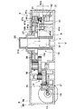
駆動装置5は、図3および図4に示すように、製氷皿2に連結されて一体的に回動しこれを反転させるカム車10と、このカム車10に回転角度に応じて連動し検氷レバー3を動作させる検氷機構11およびスイッチ機構12を備えて構成されている。なお、この駆動装置5の内部機構は、2つのケース半体9a,9bからなるケース9内に配置されている。
【0027】
カム車10は、駆動源となるDCモータ13により回転させられる。すなわち、DCモータ13の回転は、DCモータ13の出力軸13aに連結されたウォーム15、第1歯車16、第2歯車17及び第3歯車18を介してカム車10に伝達される。
【0028】
図5は、カム車10を示している。この図5は、カム車10を図4の矢示V方向から見た図でである。
【0029】
カム車10には、出力軸25が一体成形されている。この出力軸25は、一方のケース半体9aに設けられた孔から駆動装置5の外方に突出し、製氷皿2に連結されている。したがって、カム車10と製氷皿2とは、一体となって回転する。
【0030】
なお、出力軸25の製氷皿2に連結されていない側の端部は、筒状となっており、ケース半体9bに設けられた円形の台部7に回転自在に支持されている。また、この出力軸25の端部外周面には、筒状のフリクション部材8が遊嵌配置されている。
【0031】
この筒状のフリクション部材8は、出力軸25に対して摩擦力により一体的に回転可能となっている。図6に示すように、このフリクション部材8の下端縁(ケース半体9bと対向する側の端部)には、切り欠き形状の溝8aが形成されており、この溝8aの両端がケース半体9bに形成された凸部と当接可能となっている。そのため、フリクション部材8は、溝8aの両端とケース半体9b側の凸部とが当接する範囲でのみ回動可能となっている。また、フリクション部材8の内周壁には、下端縁の一部から若干上方にかけて形成された2つの平面部8c,8cが設けられている。この両平面部8c,8cは、フリクション部材8と出力軸25との一体回動をより確実なものとなるための部位となっている。このフリクション部材8と出力軸25との関係は、フリクション部材8が溝8aの両端とケース半体9b側の凸部とが当接するまで一体回動し、当接によって回転が阻止された後も、出力軸25のみが回転できるようになっている。
【0032】
また、筒状のフリクション部材8の外周面には、後述する検氷軸31の回転を阻止する阻止片8bが設けられている。この阻止片8bは、カム車10が離氷位置側に回動する場合は検氷軸31の係合片31bと係合せず、カム車10が製氷位置側に回動する場合にのみ検氷軸31の係合片31bと係合し、検氷軸31の回動を阻止するようになっている。そして、この阻止片8bによって検氷軸31の回動が阻止されると、検氷軸31に形成されたスイッチ押圧動作阻止部31dが、タクトスイッチ42をオン/オフ切り換えする回動部材としてのスイッチ押圧レバー41の回動範囲内に入り込めず、タクトスイッチ42が自在にオン/オフ切り換え可能となる。
【0033】
このフリクション部材8は、検氷動作において氷の不足と満氷とを識別するためオン/オフいずれかとなるタクトスイッチ42が、離氷位置から製氷位置に検氷レバー3が戻る際には必ず途中でオンとなるようにするためのものとなっている。すなわち、検氷動作において貯氷容器内で検氷レバー3が所定位置まで降下すると、氷が不足していると判断しそのままカム車10を離氷位置まで回転させて氷を落下させる動作を行うが、離氷位置から製氷位置に戻す際、既に先ほどの離氷により満氷状態となる場合とまだ氷が不足したままの場合とが生じる。そのため、離氷された後のタクトスイッチ42のオン/オフにバラツキが生じ、制御上好ましくない。このフリクション部材8は、このような不具合がないように、離氷位置から製氷位置への戻し動作時には必ずタクトスイッチ42がオンとなるようにするための部材となっている。
【0034】
また、カム車10の、一方のケース半体9aに対向する一側面10bには、図4に示すように、溝26が周方向に沿って形成されている。この溝26内には一方のケース半体9aの内面に形成された突起(図示省略)が挿入されており、カム車10の回転できる角度を所定の範囲に制限している。すなわち、溝26の両端面(図示省略)にケース半体9aの突起が当たる位置を、カム車10の回転限界位置としている。本実施の形態の場合には、カム車10は、−6度から168度の範囲で回転できる。なお、この回転角度は、イニシャライズの際に−6度まで回転させて機械的なロックを行う場合等を除く通常の場合は、後述するように、0度から160度の範囲で動作する。
【0035】
一方、カム車10の、他方のケース半体9bに対向する他側面10cには、図4及び図5に示すように、環状の凹部27が形成されている。この凹部27内には、内壁をカム面とする検氷軸用カム面28が設けられていると共に、その外側に同様に内壁をカム面とするスイッチ押圧レバー用カム面29を構成している。各カム面28,29は、カム車10の回転中心となる軸に対してほぼ平行に延設された延設部の側壁の内周面部分に形成されている。
【0036】
そして、検氷軸用カム面28は、検氷非動作位置部28aと、検氷降下動作部28bと、氷不足検出位置部28cと、検氷復帰動作部28dとを有している。検氷非動作位置部28aは、検氷レバー3を下降させない状態で維持させる区間となっており、カム車10の初期位置において検氷軸31と当接している位置を0度とした場合、−6度〜11度及び79度〜168度の区間に形成されている。また、検氷降下動作部28bは、氷が不足している場合に検氷レバー3を徐々に下降させるための区間となっており、11度〜35度の区間に形成されている。また、氷不足検出位置部28cは、氷が不足している場合に検氷レバー3を最下降させた状態で維持させる区間となっており、35度〜55度の区間に形成されている。また、検氷復帰動作部28dは、下降した検氷レバー3を上昇させるための区間となっており、55度〜79度の区間に形成されている。
【0037】
一方、スイッチ押圧レバー用カム面29は、製氷位置(0度)を含む−6度〜5度において信号を出力させるための第1の信号発生用カム部29aと、検氷位置(42度)を含む42度〜48度において信号を出力させるための第2の信号発生用カム部29bと、離氷位置(160度)を含む160度〜168度において信号を出力させるための第3の信号発生用カム部29cとを有している。この構成により、カム車10の回転角度が、製氷位置、検氷位置及び離氷位置にある場合に、タクトスイッチ42を押圧する方向にスイッチ押圧レバー41を回動させるようになっている。
【0038】
なお、製氷位置において発生する信号を原位置信号と呼ぶこととし、第1の信号発生用カム部29aは、その形状上、−19度〜5度の範囲で信号を発生できるようになっている。また、検氷位置において発生する信号を検氷位置信号と呼ぶこととする。さらに、離氷位置において発生する信号を離氷信号と呼ぶこととし、第3の信号発生用カム部29cは、その形状上、160度〜179.5度の範囲で信号を発生できるようになっている。
【0039】
検氷機構11は、貯氷容器内の氷の量が、満氷であるのか不足しているのかを識別するための機構となっており、検氷レバー3を貯氷容器内に下降させ、所定レベル位置より下降した際に氷が不足していると判断するようになっている。なお、検氷機構11は、カム車10の検氷軸用カム面28に摺動する摺動部31aを備え、カム車10の回動角度に応じて回転すると共に、この回転により検氷レバー3を動作させる検氷軸31と、この検氷軸31に圧縮状態で当接配置され、摺動部31aを検氷軸用カム面28側に圧接する方向に検氷軸31を付勢する圧縮バネとしての圧縮コイルバネ32から構成されている。そして、本実施の形態の自動製氷機の駆動装置1では、検氷レバー3が30度以上回動した場合、これを氷不足と判断するようになっている。
【0040】
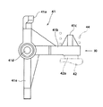
検氷軸31は、カム車10によって操作され、最大35度まで回動可能となっている。この検氷軸31は、ケース半体9bの底面上に配置された圧縮コイルバネ32の上側(ケース半体9a側)に十字状に重なるように配置されている。すなわち、ケース半体9bの底面側から圧縮コイルバネ32、検氷軸31、カム車10という順序で配置されることにより、圧縮コイルバネ32及び検氷軸31はカム車10とケース半体9bとの間に配置されている。検氷軸31は、図7及び図8に示すように、摺動部31aと、係合片31bと、バネ係合部31cと、スイッチ押圧動作阻止部31dと、スラスト抜け防止突堤31eと、レバー連結部31fと、ケース受け部31gと、ガイド片31hを有している。
【0041】
検氷軸31の一方の端部の凸部で構成されたケース受け部31gは、ケース半体9bに形成された受け孔(図示省略)に回動自在に支持される。一方、この検氷軸31の他方の端部に形成されているレバー連結部31fは、ケース9の外部に突出されていると共に、このレバー連結部31fに検氷レバー3の支点部が嵌め込まれる。
【0042】
また、検氷軸31のケース受け部31gの近傍に形成された摺動部31aは、検氷軸31の外周面から径方向外側に突出され途中位置から湾曲された形状となっており、検氷軸31と共に回転中心軸線を回転中心として回動可能となっている。そして、摺動部31aは、カム車10に形成された検氷軸用カム面28に当接するカムフォロアーとなっている。
【0043】
また、同様に、検氷軸31の端部近傍に設けられた係合片31bは、出力軸25と同軸上に配置されたフリクション部材8の阻止片8bと当接可能とされている。さらに、バネ係合部31cは、検氷軸31の軸方向中央よりややケース受け部31g側の端部に近い側に、圧縮コイルバネ32と当接するように設けられている。そのため、検氷軸31は、圧縮状態で配置された圧縮コイルバネ32の図8の矢示B方向の戻り力によって摺動部31aをカム車10の検氷軸用カム面28側に押し付ける方向(図8の矢示A方向)に回動するように付勢される。なお、このバネ係合部31cの圧縮コイルバネ32と当接する側と反対側の面には、後述する仮保持時において、バネボックス52のスリット9fに形成された突出部9gに引っ掛かる突起31jが設けられている。
【0044】
また、スイッチ押圧動作阻止部31dは、検氷軸31のレバー連結部31f側の端部近傍に設けられ、タクトスイッチ42のオン/オフを行う回動部材としてのスイッチ押圧レバー41の回動を、検氷レバー3の降下状況に応じて阻止しスイッチ押圧動作を阻止するようになっている。このスイッチ押圧動作阻止部31dは、検氷軸31が検氷レバー3を下降させるように回動した際に、具体的には検氷軸31が30度以上回動した際、スイッチ押圧レバー41に当接しスイッチ押圧レバー41の回動を阻止するようになっている。これによって、スイッチ押圧動作阻止部31dは、検氷軸31が30度以上回動した際には、タクトスイッチ42をオンさせないように働く。
【0045】
また、スラスト抜け防止突堤31eは、検氷軸31の軸方向におけるスイッチ押圧動作阻止部31dとレバー連結部31fとの間に全周に渡って形成されている。このため、検氷軸31は、スラスト方向において所定の範囲のみ移動可能となっている。
【0046】
さらに、ガイド片31hは、検氷軸31の軸方向中央よりややレバー連結部31f側に近い位置に形成されている。このガイド片31hは、ケース半体9aの天板の裏側部分に形成されたガイド溝9h(図3中の点線で表示)内に入り込み、このガイド溝に沿って移動するようになっている。すなわち、ケース半体9aに形成されたガイド溝は、検氷軸31の回動範囲を規制する回動規制部となっている。このため、検氷軸31は、ガイド片31hによってケース半体9aに対して案内され、このガイド溝内でガイド片31hが移動可能な範囲でのみ回動できるようになっている。なお、この検氷軸31の回動範囲は、約35度程度となっている。
【0047】
このように構成された検氷機構11は、検氷軸用カム面28に沿って動作する検氷軸31の動きを検氷レバー3に伝える。すなわち、検氷レバー3が満氷によってその動きを停止すると、検氷軸31は、検氷レバー3と共にその回転を停止する。また、検氷機構11は、検氷動作時に氷が不足し検氷レバー3が所定角度以上回動している場合、スイッチ押圧レバー用カム面29によるスイッチ押圧レバー41の動作を規制するようになっている。このため、検氷動作時に氷が不足している場合は、スイッチ押圧レバー41が回動せず、タクトスイッチ42を押圧しないようになっている。
【0048】
圧縮コイルバネ32は、検氷軸31に圧縮状態で当接配置され、検氷軸31の摺動部31aを検氷軸用カム面28側に押しつけるように、検氷軸31を付勢するものとなっている。なお、圧縮コイルバネ32の付勢力は、少なくとも、検氷軸31のスイッチ押圧動作阻止部31dがスイッチ押圧レバー41のスイッチ押圧動作を阻止することが可能な程度に設定されている。すなわち、スイッチ押圧レバー41は、後述するようにコイルスプリング44によってタクトスイッチ42を押圧する方向に付勢されているが、このバネ力に抗してスイッチ押圧レバー41のスイッチ押圧部(後述する突起腕41bに相当)を持ち上げる程度に、圧縮コイルバネ32の付勢力が設定されている。
【0049】
この圧縮コイルバネ32は、検氷軸31の奥側、すなわちケース半体9bの底面側に配置されており、組立の際には検氷軸31よりも先にケース半体9b内に組み込まれる。この圧縮コイルバネ32は、図3及び図9に示すように、検氷軸31の組み込み前に、バネボックス52内に圧縮した状態で一旦保持される。
【0050】
バネボックス52は、図9に示すように、上方が開放され、1つの側壁がケース半体9bの側壁9dで構成され、他の3つの側壁がケース半体9bの底面から立設される壁部で構成されている。そして、検氷軸31の組み込み前の圧縮コイルバネ32は、一端がケース半体9bの側壁9dに、他端が他の3つの側壁のうちの側壁9dと平行な位置に配置されケース半体9bの底面に立設された壁部9eに支持されている。
【0051】
圧縮コイルバネ32の他端を支持する支持部としての壁部9eの中央よりやや検氷軸31の突出口方向側の位置には、スリット9fが設けられている。そして、スリット9fの切り口の検氷軸31のケース受け部31g側に配置される端面には、バネボックス52の内部空間方向へ突出するように形成された突出部9gが形成されている。
【0052】
検氷軸31は、圧縮状態で圧縮コイルバネ32が装填されているバネボックス52のスリット9fをバネ係合部31cが通過した後に、このバネ係合部31cが圧縮コイルバネ32の一端に係合するように回転させて、圧縮コイルバネ32をさらに圧縮させるように組み込まれる。そして、この圧縮コイルバネ32を圧縮させた状態で、検氷軸31をケース受け部31g側(図9において矢示Y1方向)へ若干移動させる。この状態で、検氷軸31に圧縮コイルバネ32の付勢力を受けさせると、検氷軸31は、上述の装填時とは反対方向へ回動しようとする。
【0053】
しかしながら、このとき検氷軸31は、上述したように図9において矢示Y1方向へ若干移動した状態となっているため、反対方向へ回動しようとしてもバネ係合部31cがスリット9fを通過してバネボックス52の外側飛び出さすことはない。すなわち、バネ係合部31cがバネボックス52の壁部9eに当接し、検氷軸31の回動が阻止される。すなわち、この壁部9eは、圧縮コイルバネ32の付勢力によって回動しようとする検氷軸31の回動阻止部となっている。
【0054】
また、検氷軸31は、このときの圧縮コイルバネ32の付勢力を受けることにより、若干、図9において矢示Y2方向へ戻ろうとする。しかしながら、このとき、検氷軸31は、バネ係合部31cに形成された突起31jがスリット9fに形成され突出部9gに引っ掛かかるため、スラスト方向(図9において矢示Y2方向)への移動を阻止される。このため、検氷軸31は、バネボックス52内で圧縮コイルバネ32を圧縮させた状態で仮保持される。
【0055】
そして、この仮保持状態でカム車10が、検氷軸用カム面28が検氷軸31の摺動部31aと対向する位置に配置されるように組み込まれる。この時点では、検氷軸用カム面28は、摺動部31aと当接していない。この後、検氷軸31のガイド片31hがガイド溝9h内にはまり込むようにケース半体9aを、ケース半体9bに被せる。これにより、検氷軸31がガイド溝9hに案内されて、圧縮コイルバネ32を圧縮させる方向へ若干回動する。このようにカム車10及びケース半体9aが装填され、検氷軸31が若干回動すると、検氷軸31の突起31jは、バネボックス52の壁部9e及びこの壁部9eに形成された突出部9gから離れる。
【0056】
すなわち、カム車10を装填しケース半体9aをケース半体9bに被せた後は、検氷軸31は組み付け時の仮保持部としての壁部9e及び突出部9gには当接しないようになっており、壁部9e及びこの壁部9eに形成された突出部9gは、カム車10によって操作される検氷軸31の正規の回動領域外に形成されている。このように、カム車10は、検氷軸31が仮保持された状態で装填されるため、圧縮コイルバネ32のバネ力を受けないで容易に組み込むことができる。なお、上述した順序で、具体的には圧縮コイルバネ32、検氷軸31、カム車10を組み込んだ後、最後にケース半体9aをケース半体9bに被せることにより、組み込み作業が終了する。
【0057】
なお、本実施の形態では、上述したようにスリット9fにバネボックス52の内側に突出する突出部9gを設け、この突出部9gで検氷軸31に形成された突起31jを引っ掛けて組み込み時の仮保持を行うように構成したが、他の方法で仮保持を行うようにしても良い。例えば、スリット9f間にケース半体9bの底面から立設させた突起を備え、この突起にバネ係合31cの圧縮コイルバネ32と当接する側とは反端側の面を当接させるようにしても良い。また、上述した突出部9gやスリット9f間に形成される突起等は、検氷軸31の正規の回転領域外に設けることにより、仮保持の場合のみ検氷軸31の突起31jと当接するようにしても良いし、正規の回転領域内に設けて機械的なロック位置としても良い。
【0058】
圧縮コイルバネ32は、検氷レバー3を常時検氷位置側へ付勢するようになっている。すなわち、検氷軸用カム面28に対し、検氷軸31の摺動部31aを当接させる方向に付勢力を与えている。この力は、カム車10の中心から外周に向かうものであるが、カム車10を組み込むときの妨げとならない力となるように組み込まれる。このため、カム車10が圧縮コイルバネ32の力によって傾いたり浮き上がってしまうことがない。カム車10を組み込んだ後、最後にケース半体9aを組み付けることによって、検氷軸31のガイド片31hがケース9のガイド溝9hに導入され、検氷軸31は正規の回動範囲の限界となる35度回転した状態となる。このように検氷位置で35度回転した状態で組み込まれた後、駆動回路で駆動し製氷位置とした後に出荷される。
【0059】
スイッチ機構12は、製氷皿2の駆動に連動して接点の係合及び離脱がなされることによりオン/オフ切り換えがなされるようになっている。このスイッチ機構12は、カム車10のスイッチ押圧レバー用カム面29に沿って回動操作される回動部材としてのスイッチ押圧レバー41と、スイッチ押圧レバー41の回動によってオン/オフ切り替えがなされるタクトスイッチ42と、スイッチ押圧レバー41の回動によるスイッチ押圧動作を禁止するように働くスイッチ押圧動作阻止部31dと、スイッチ押圧レバー41を回動させるための力を与えるコイルスプリング44とを備えて構成されている。
【0060】
スイッチ押圧レバー41は、一方のケース半体9bの底面に立設された2つの端板53の上端縁部分に設けられた各U字状溝53a内に回動自在に支持されている。スイッチ押圧レバー41は、図10及び図11に示すように、側面から見ると「ト」の字の形状を有している。そして、上端部分には、カム車10のスイッチ押圧レバー用カム面29に当接するカムフォロアーとなるカム当接部41aが設けられている。したがって、カム車10が回転した場合、カム当接部41aがスイッチ押圧レバー用カム面29に沿ってカム車10の径方向に移動し、スイッチ押圧レバー41が回動する。
【0061】
また、スイッチ押圧レバー41の所定位置には、コイルスプリング44によってタクトスイッチ42を押圧する方向に付勢される被押圧部となる突起腕41bが形成されている。この突起腕41bは、検氷軸31に設けられたスイッチ押圧動作阻止部31dの近傍に位置している。この突起腕41bにスイッチ押圧動作阻止部31dが当たっている状態では、スイッチ押圧レバー41は回動することができない。
【0062】
一方、突起腕41bと対向する位置には、タクトスイッチ42のボタン42aが配置されている。また、スイッチ押圧レバー41の突起腕41bのタクトスイッチ42と対向しない側の面には山形状の突部41cが設けられ、コイルスプリング44の一端内に入り込んでいる。なお、コイルスプリング44の他端は、ケース半体9aに設けられた係合筒21c内に入れられ、係合筒21c内の軸(図示省略)がその端部内に入り込んでいる。
【0063】
また、スイッチ押圧レバー41の中心部は、揺動を支える回動支持部41dとなっており、この回動支持部41dの両端が各U字状溝53a内に入り、この回動支持部41dを中心として回動する。さらに、このスイッチ押圧レバー41には、揺動規制部41eが設けられており、この揺動規制部41eはケース半体9bに備えられた規制用ボックス内に装填される。そのため、スイッチ押圧レバー41は、回動支持部41dの片方がU字状溝53aの底部から浮き上がって傾くことがなく、揺動中心がずれずに正確にスイッチ押圧レバー用カム面29に沿って動作するようになっている。
【0064】
タクトスイッチ42は、ケース半体9bに固定され、DCモータ13の後端に連結されたプリント配線基板51に接続されている。このタクトスイッチ42は、スイッチ押圧レバー41が非作動状態、すなわちカム車10が0度位置にあり駆動停止状態で氷の製造がなされている場合や、検氷動作時に満氷であった場合や、離氷動作が終了する場合にコイルスプリング44の付勢力を受けたスイッチ押圧レバー41によって押圧されるように配置されている。この押圧によって原位置信号、検氷信号、離氷信号が発生する。なお、製氷皿2がこれら以外の位置となっている場合、タクトスイッチ42はスイッチ押圧レバー41に押圧されず、オフとなる。
【0065】
このように製氷位置で常時オンとなっているタクトスイッチ42は、検氷動作をし貯氷容器内の氷が不足の場合、カム車10が製氷位置(0度)から離氷位置(160度)まで回転するまでオンとならない。すなわち、このタクトスイッチ42は、カム車10が5度回転するとカム車10によりスイッチ押圧レバー41がスプリングコイル44の付勢力に抗してタクトスイッチ42から離れ、一旦タクトスイッチ42はオフとなる。
【0066】
そして、カム車10が42度回転した際に、カム車10及びスプリングコイル44のバネ力によりスイッチ押圧レバー41を回動させようとするが、このとき検氷軸31のスイッチ押圧動作阻止部31dが働いて、このスイッチ押圧レバー41の回動を阻止する。この結果、氷不足状態で検氷軸31が所定角度(ここでは30度)以上回動している場合は、この検氷信号が発生すべき位置、すなわちカム車10の回動角度が42度〜48度ではタクトスイッチ42がオンとならず、検知信号が出力されないようになっている。そのため、タクトスイッチ42は、カム車10が160度回転した離氷位置となるまでオンとならない。
【0067】
一方、タクトスイッチ42は、検氷動作をし貯氷容器内の満氷の場合、カム車10が製氷位置(0度)から検氷位置(42度)まで回転するとオンとなる。すなわち、タクトスイッチ42は、上述したようにカム車10が5度回転すると一旦オフとなるが、カム車10が42度回転した際に、カム車10及びスプリングコイル44のバネ力により、再びスイッチ押圧レバー41を回動させようとする。
【0068】
このとき、検氷レバー3は貯氷容器内が満氷のため容器内で所定位置まで降下しない。そのため、検氷軸31が所定角度以上回転せず、検氷軸31のスイッチ押圧動作阻止部31dが働かない。この結果、スイッチ押圧レバー41は、回動してタクトスイッチ42のボタン42aを押圧しタクトスイッチ42がオンとなる。
【0069】
なお、本実施の形態の自動製氷機の駆動装置は、検氷動作を開始した後の最初の信号出力及び駆動時間に基づいてカム車10を逆回転させる制御を行っている。そのため、満氷時にはカム車10を42度回転させた時点、氷が不足していた時にはカム車10を160度回転させた時点でDCモータ13を停止させ、その後逆回転させるような制御を行っている。
【0070】
なお、カム車10を42度回転させた際の最初の信号出力でDCモータ13を停止させた場合は、その駆動時間が短いことをモニターし、これに基づいて逆回転後の最初の信号出力に基づいてDCモータ13の駆動を停止する。これによって、カム車10は原位置(0度=製氷位置)またはその周辺位置にて停止する。
【0071】
一方、カム車10を160度回転させた際の最初の信号出力でDCモータ13を停止させた場合は、その駆動時間が長いことをモニターし、これに基づいて逆回転後の2度目の信号出力に基づいてDCモータ13の駆動を停止する。すなわち、最初の信号出力はカム車10が48度〜42度の位置まで戻されたことを示す信号(復帰時の確定信号)で、2度目の信号がカム車10として5度となる位置まで戻されたことを示す信号であるため、2度目の信号に基づいて、DCモータ13を停止させる。これによって、カム車10は原位置(0度=製氷位置)またはその周辺位置にて停止する。なお、戻り行程におけるカム車10が48度〜42度となった際の信号出力は、フリクション部材8によって氷が不足していても充足していても、いずれの場合にも発生するようにされている。
【0072】
なお、上述したスイッチ押圧レバー用カム面29には、3ヶ所の位置に凹み部分が設けられている。この3つの凹みが、上述した第1、第2及び第3の信号発生用カム部29a,29b,29cとなっており、スイッチ押圧レバー41のカム当接部41aがこれらの凹み部分に嵌まり込むたびにスイッチ押圧レバー41はタクトスイッチ42側に揺動しようとする。この揺動時に、検氷軸31のスイッチ押圧動作阻止部31dが働かないと、タクトスイッチ42はオンとなるようになっている。
【0073】
次に、この自動製氷機1の動作について説明する。コントローラ(図示省略)は、基本動作プログラムおよび初期設定プログラムを適宜実行し、図12に示すように動作する。なお、初期設定プログラムや基本動作プログラムを実行するためにコントローラを制御駆動する制御回路は、自動製氷機1が取り付けられた冷蔵庫本体(図示省略)に備えられたものと共用となっていても良いし、自動製氷機1専用のものとなっていても良い。
【0074】
まず、電源オンまたは初期化する旨の信号のいずれかがコントローラに入力されると、初期設定プログラム(イニシャライズの動作モード)が開始される。この初期設定プログラムは、この自動製氷機1単体での動作確認、冷蔵庫に取り付けたときの動作確認、冷蔵庫を移動したときの初期動作の際等に実行するもので、製氷皿2の位置を確認し、水平位置状態とするものである。
【0075】
すなわち、電源オンにより、DCモータ13をCCW方向、すなわちカム車10を製氷位置(原点位置=0度)へ戻す方向へ回転させる。そして、タクトスイッチ42がオンとなったら、タイマーを3秒にセットし、スイッチオン状態が継続したままタイマーの動作が終了したら、DCモータ13を1秒間停止させる。
【0076】
この動作で、カム車10は、メカロック位置(−6度)で停止する。すなわち、初期設定動作において、DCモータ13をCCW方向へ回転させた際、最初にスイッチがオンとなって出力される信号が検氷信号なのか原位置信号なのかを認識するために、最初の信号出力後、タイマーを3秒にセットする。そして、スイッチがオン状態のまま3秒が経過する場合を、原位置信号として認識し、3秒経過する前にスイッチがオフとなって信号出力が途絶える場合を検氷出力として認識するようにする。これにより、確実にカム車10がロック位置(−6度)で停止する。
【0077】
次に、DCモータ13をCW方向、すなわちカム車10を検氷位置及び離氷位置方向へ回転させる。そして、タクトスイッチ42がオフとなったら、タイマーを0.5秒にセットし、タイマーの動作が終了したら、DCモータ13を1秒間停止させる。
【0078】
その後、DCモータ13をCCW方向へ回転させる。そして、タクトスイッチ42がオンとなったら、タイマーを0.5秒にセットし、タイマーの動作が終了したらDCモータ13を停止させる。これによって、DCモータ13は、この初期設定動作においてカム車10が製氷位置(0度=原位置)近傍となった位置で停止する。これによって、自動製氷機1の初期設定プログラム実行時(イニシャライズ)の動作が終了する(ステップS28)。
【0079】
上述のイニシャライズが終了すると、通常の動作を行うための基本動作プログラムへ移行する。この基本動作プログラムは、例えば、扉が開かれていない状態であることおよび製氷皿2の下に置かれるサーミスタ1aによって製氷完了を検知した後、一定時間経過することというAND条件が満たされたとき、待機終了の旨の信号がコントローラに入力し実行するようにされる。
【0080】
これにより、コントローラは氷製造が終了したと判断し、貯氷容器内の氷の量を検知させる。なお、この基本動作プログラムは、初期設定からスタートした場合は、製氷皿2内に氷が無い状態であるが、サーミスタ1aは、氷の有無にかかわらず庫内温度を感知するので、氷製造が終了したと判断するように設定されている。
【0081】
コントローラは、貯氷容器内の氷が不足状態か否かを検知し、満氷でないとき、すなわち氷が不足状態であると、製氷皿2を反転させ氷を貯氷容器へ供給する離氷を行う。次に、原点位置(0度)まで逆方向に回転させ給水を行う。これによって、製氷皿2は、水平位置に戻り製氷がなされる。一方、満氷状態であると、製氷皿2は反転せず原点(=水平位置)に戻り、検氷のため所定時間待機し、製氷確認に戻っていく。
【0082】
次に検氷動作について詳述する。まず、製氷が完了したら、DCモータ13をCW方向へ回転させる。そして、タクトスイッチ42がオフとなったら、タイマーを7秒にセットする。この間、スイッチオフ状態が維持された状態でタイマー動作が終了した後、タクトスイッチ42がオンに切り換わった場合は、離氷信号が発生したこととなり、DCモータ13を1秒間停止させる。なお、この場合は、検氷動作において氷が不足していたこと及びこの氷の不足に基づき離氷動作を行ったことを意味する。
【0083】
すなわち、氷が不足している場合には、カム車10が所定角度(42〜48度)回転した際に、検氷軸31も所定量降下した状態となっており、これによってスイッチ押圧動作阻止部31dが働いてスイッチ押圧レバー41がタクトスイッチ42を押圧しない。したがって、このような状況の場合は、タクトスイッチ42がオンとならず信号が出力されないからである。
【0084】
なお、氷不足を検知し、DCモータ13を1秒間停止させた後、今度はDCモータ13をCCW方向へ回転させる。そして、タクトスイッチ42がオフとなることで離氷信号がオフし、次にタクトスイッチ42がオンとなることで復帰時の確定信号(検氷信号)がオンする。さらに、タクトスイッチ42がオフとなることで検氷信号がオフし、次にタクトスイッチ42がオンとなったら、原位置信号と判断し、タイマーを0.5秒にセットする。
【0085】
このようにタクトスイッチ42の2度目のオンに基づいてタイマーをセットするのは、この2度目のオンがカム車10が5度の位置に戻ってきたことを示すからである。すなわち、離氷動作をした後、カム車10が所定位置(42〜48度)まで回転した際に、検氷軸31はフリクション部材8の阻止片8bに阻止されて回動できず、これによってスイッチ押圧動作阻止部31dが働けずにスイッチ押圧レバー41がタクトスイッチ42を押圧する。したがって、このような状況の場合は、タクトスイッチ42がオンとなり1度目のオン信号が出力されるからである。
【0086】
そして、2度目のオン信号から0.5秒が経過してタイマーの動作が終了したら、DCモータ13を停止させる。これによって、カム車10は、原位置(0度)近傍で停止することとなる。この後、製氷皿2に給水を行い、一連の検氷動作及び離氷動作が終了する。
【0087】
なお、検氷動作によってタクトスイッチ42がオンとなった場合(この場合は42度の位置でオンとなる=氷の量は満氷)、このスイッチオンに基づきDCモータ13を1秒間停止させる。その後、今度はDCモータ13をCCW方向へ回転させる。そして、タクトスイッチ42がオフとなることで検氷信号がオフし、次にタクトスイッチ42がオンとなったら、原位置信号と判断しタイマーを0.5秒にセットする。
【0088】
そして、0.5秒が経過してタイマーの動作が終了したら、DCモータ13を停止させる。これによって、カム車10は、原位置(0度)近傍で停止することとなる。この後は、製氷皿2に氷がある状態なので給水は行わず待機状態となる。これによって、満氷時の検氷動作が終了する。
【0089】
なお、上述の実施の形態は本発明の好適な実施の例ではあるが、これに限定されるものではなく、本発明の要旨を逸脱しない範囲において種々変形実施可能である。例えば、上述の実施の形態では、検氷軸31を付勢する圧縮バネを圧縮コイルバネ32で構成したが、圧縮ゴムバネ等、他の圧縮バネとしても良い。さらに、上述の実施の形態では、検氷位置等を検出するスイッチをタクトスイッチ42で構成したが、接点の係合/離脱によりオン/オフ切り換えがなされるリーフスイッチ等を用いても良い。
【0090】
また、上述の実施の形態では、出力軸25をカム車10と一体的に設けたが、一体的に設けず別体としても良い。その際、それらを別の駆動源で駆動するようにしても良い。また、カムフォロアーとなる検氷軸31の摺動部31aや、スイッチ押圧レバー41のカム当接部41aをカム車10の内周面に当接させるのではなく、外周面に当接させるようにしても良い。
【0091】
さらに、上述の実施の形態では、検氷信号を満氷の場合のみ発生するようにしたが、満氷のときは発生させず不足状態のときに信号を発生させるようにしても良い。
【0092】
さらに、駆動源をDCモータ13ではなく、ACモータやコンデンサモータとしてもよい。さらに、DCモータ13のように、時間制御がある程度必要なモータを使用するのではなく、ステッピングモータを使用してカム車10の回転角度をステップ数で制御するようにしても良い。さらには、ソレノイド等モータ以外の駆動源を採用しても良い。また、氷化する液体としては、水の他にジュース等の飲み物や検査試薬等の非飲料等を採用することができる。また、貯氷容器内の氷が出来上がったか否かを検知する手段としては、サーミスタ1aの他に形状記憶合金等を利用したバイメタルとしても良い。
【0093】
【発明の効果】
以上説明したように、本発明の自動製氷機の駆動装置は、貯氷容器内の氷の量を検出する検氷レバーを動作させる検氷機構の検氷軸の回転駆動源として圧縮状態で検氷軸に当接配置された圧縮バネを用いている。このため、組み付けスペースが制限されにくくなり、自由長(動作範囲中、最大伸張した状態の長さ)を小さく設定することが可能となり、狭いスペースでも十分なストロークと付勢力とが得られる。また、組み込み時及び組み込み後の検氷軸やバネの外れ等の不具合が生じにくく、信頼性の高い装置とすることができる。また、引っ張りバネのように両端に引っ掛け用の係止部が設けられる構造とはなっておらず、所定の位置に載置して圧縮した状態で検氷軸を当接させるように構成されているため、組立作業性が良く、低コストで組み込むことが可能となる。
【0094】
また、圧縮バネの付勢力による検氷軸の回動を阻止する回動阻止部を設けると、圧縮バネの付勢力による検氷軸の回動で当該装置を破壊したり、あるいは検氷軸自体が破壊されてしまうという危険性がない。また、回動阻止部を、組立時(カム歯車及びケースの蓋を被せる前の段階)における検氷軸の仮保持部として使用すれば、この部位の強度が必要なくなり組立作業性が向上すると共に設計コストや材料コストを安価とすることできる。
【0095】
また、上述の自動製氷機の製造方法によれば、係止部への引っ掛け作業等の煩雑な作業をすることなく簡単な操作で、圧縮バネをバネボックス内で確実に保持させ、その後、検氷軸を圧縮バネを圧縮させながら当接させるという簡単な作業で圧縮バネ及び検氷軸が保持される。この状態からカム車及びケース半体を嵌め込むだけで、圧縮バネ及び検氷軸が外れることなく確実にケース内に収まる。そのため、組立性がよく、組立コストを低減することが可能となる。
【図面の簡単な説明】
【図1】本発明の実施の形態の自動製氷機の要部平面図である。
【図2】図1の自動製氷機の側面図である。
【図3】図1の自動製氷機の駆動装置を示し、一方のケースを取り外して内部を観察可能にした正面図である。
【図4】図3の駆動装置の回転伝達手段の連結関係を示す断面展開図である。
【図5】図4の矢示V方向から駆動装置のカム歯車を示した図である。
【図6】図4の駆動装置のフリクション部材を示した図で、(A)は図4の裏側から見た背面図、(B)は(A)を矢示VIB方向から見た図、(C)は(B)のVIC−VIC断面図である。
【図7】図3の駆動装置の検氷軸を示した正面図である。
【図8】図7のVIII−VIII断面図である。
【図9】図3の駆動装置のバネボックス周辺を拡大して示した部分拡大平面図である。
【図10】図3の駆動装置のスイッチ押圧レバーを矢示X方向から見た底面図である。
【図11】図10を矢示XI方向方見た側面図である。
【図12】図1の自動製氷機の動作状況を示す図である。
【図13】従来の自動製氷装置をケースの蓋を外した状態で内部機構が見えるように示した平面図である。
【符号の説明】
1 自動製氷機
2 製氷皿
3 検氷レバー
5 駆動装置
9 ケース
9a,9b ケース半体
9d (ケースの)側壁
9e 壁部(回動阻止部)
9f スリット
9g 突出部
9h ガイド溝(回動規制部)
10 カム車
11 検氷機構
12 スイッチ機構
13 DCモータ
25 出力軸
28 検氷軸用カム面
29 スイッチ押圧レバー用カム面
31 検氷軸
31a 摺動部
31d スイッチ押圧動作阻止部
32 圧縮コイルバネ
41 スイッチ押圧レバー(回動部材)
42 タクトスイッチ[0001]
BACKGROUND OF THE INVENTION
The present invention relates to a drive device for an automatic ice maker and a method for manufacturing the device for replenishing the manufactured ice when it is installed in a refrigerator to manufacture ice and when the lack of ice in an ice storage container is detected.
[0002]
[Prior art]
In recent years, home refrigerators and the like having an automatic ice making function are known, and a drive device for an automatic ice making machine attached to this type of refrigerator is disclosed in, for example, Japanese Patent Laid-Open No. 10-78277. There are automatic ice making equipment.
[0003]
FIG. As shown in FIG. 1, the automatic ice making apparatus described in Japanese Patent Laid-Open No. 10-78277 reduces the rotational force of the
[0004]
On the other hand, the
[0005]
That is, the
[0006]
[Problems to be solved by the invention]
In the above-described automatic ice making device, the ice making tray is driven to rotate and the
[0007]
In general, the hook for locking the end of the tension coil spring is formed so as to have a straight shape in the mold drawing direction due to the structure of the mold. For this reason, there is a problem in that the state in which the tension coil spring is hooked on the hook is unstable and easily detached from the hook during assembly work (before the two case halves constituting the case are fitted). For this reason, the assembling work becomes more complicated, and the manufacturing cost further increases. Moreover, there is a possibility that the case where the case is assembled with the tension coil spring detached is also caused.
[0008]
Furthermore, in the above-mentioned automatic ice making device, the rotation range of the
[0009]
In the present invention, the ice detecting shaft that rotates in synchronization with the rotation angle of the ice tray and the urging means that applies the rotational force to the ice detecting shaft are securely locked in a narrow space, and with sufficient torque. It is an object of the present invention to provide a drive device for an automatic ice making machine capable of rotating an ice detecting shaft and facilitating assembly work, and a method for manufacturing the device.
[0010]
[Means for Solving the Problems]
In order to achieve such an object, in the present invention, when the lack of ice in the ice storage container is detected, the ice tray is inverted to drop the ice into the ice storage container, and then the ice tray is returned to its original position to return the ice. In the drive device of an automatic ice making machine that manufactures, the cam wheel that rotates integrally with the ice tray, and the amount of ice in the ice storage container descends in conjunction with the rotation angle of this cam wheel An ice detecting mechanism for operating an ice detecting lever for detecting the ice is provided in the case. The ice detecting mechanism includes a sliding portion that slides on the cam surface of the cam wheel, and rotates according to the rotation angle of the cam wheel. At the same time, the ice detecting shaft that operates the ice detecting lever by this rotation and the ice detecting shaft are arranged in contact with the ice detecting shaft in a compressed state, and the ice detecting shaft is urged in the direction in which the sliding portion is pressed against the cam surface of the cam wheel. It consists of a compression spring.
[0011]
According to the above-described invention, since the biasing means for applying the rotational force to the ice detecting shaft is constituted by the compression spring, the assembly space is not easily restricted, and the free length (the length in the maximum extended state during the operation range) is obtained. ) Can be set small, and a sufficient stroke and urging force can be obtained even in a narrow space. In addition, it does not have a structure in which hooks are provided at both ends like a tension spring, and is configured to abut the ice detecting shaft in a compressed state by placing it at a predetermined position. Therefore, the assembly workability is good and it is possible to incorporate at low cost.
[0012]
According to another aspect of the invention, in addition to the drive device for the automatic ice making machine described above, the case includes a cup-shaped case half that places each part of the device at a predetermined position inside the case, and the one case. The compression spring is arranged in the case on the bottom side of one case half from the ice detecting shaft in the case. Therefore, after the compression spring is disposed at a predetermined position on the bottom surface side in one case half, the ice detecting shaft may be disposed from the upper side, and the assembly workability is further improved.
[0013]
In another aspect of the invention, in addition to the above-described automatic ice maker driving device, one case half is provided with a rotation preventing portion that prevents rotation of the ice detecting shaft due to the urging force of the compression spring. Therefore, it is possible to prevent a risk that the ice detecting shaft breaks the apparatus or the ice detecting shaft itself is broken due to the rotation of the ice detecting shaft by the urging force of the compression spring. In addition, if this rotation prevention part is used as a temporary holding part of the ice detecting shaft at the time of assembling (the stage before covering the cam gear and the case cover), the assembling workability is further improved.
[0014]
Further, in another invention, in addition to the above-mentioned automatic ice maker driving device, the rotation preventing portion is a temporary holding portion in a state before one case half is covered with the other case half, and the other The other case half is provided with a rotation restricting portion for restricting the rotation range of the ice detecting shaft so that the ice detecting shaft and the temporary holding portion are not in contact with each other after the case half is assembled. For this reason, the assembly workability is good because it is firmly held during assembly. In addition, when the rotation preventing portion is a mere temporary holding portion at the time of assembling work and does not apply a force during normal driving, the strength of the rotation preventing portion is not so great. Thereby, reduction of design cost and material cost is attained.
[0015]
In another aspect of the invention, in addition to the above-described automatic ice maker driving device, the compression spring is disposed at a position overlapping vertically with respect to the ice detecting shaft in the case. Therefore, dead space in the case can be reduced and a compact configuration can be achieved.
[0016]
Further, in another invention, in addition to the above-described automatic ice maker driving device, the side wall of the case serves as a support portion for supporting one end of the compression spring, and the other end of the compression spring before the ice detecting shaft is incorporated. The supporting portion to be supported is a wall portion erected from the bottom surface of the case. For this reason, one end of the compression spring is efficiently supported by the side wall of the case without providing a special support member, and the other end is also securely supported, so that the compression spring can be removed before the ice detecting shaft is assembled. It can be surely prevented.
[0017]
In addition to the above-described automatic ice maker driving device, the invention also turns on and off a switch for detecting the position of the ice tray by being rotated along the cam surface of the cam wheel, and a spring. A rotating member that is biased in the direction of pressing the switch by force, and the ice detecting shaft includes a switch pressing blocking unit that blocks the switch pressing operation of the rotating member according to the descending state of the ice detecting lever; The biasing force of the compression spring is set to such an extent that the switch pressing operation of the ice detecting shaft can be prevented.
[0018]
Therefore, it is possible to switch on / off the switch by using the rotation operation of the ice detection shaft.For example, the switching timing of the switch that performs the switching operation according to the rotation angle of the cam gear is determined based on the ice detection result. It can be reflected and further diversified. As a result, for example, when driving in the direction of the deicing position, when the ice tray is at a predetermined angle, the switch is turned on / off depending on the amount of ice in the ice storage container. When rotating in the direction of the ice making position, the switch can be turned on at a predetermined angle regardless of the amount of ice in the ice storage container.
[0019]
According to another invention, a cam wheel that rotates integrally with the ice tray, an ice detecting shaft that has a sliding surface that slides on the cam surface of the cam wheel, and presses the ice detecting shaft against the cam surface. A compression spring that biases in the direction and a case that houses each part, and when the lack of ice in the ice storage container is detected, the ice tray is inverted to drop the ice into the ice storage container, and then the ice tray In a manufacturing method of manufacturing a drive device for an automatic ice maker that returns ice to its original position and manufacturing ice, a compression spring is provided in a spring box formed on one bottom surface side of two divided case halves constituting the case Is placed in a compressed state, the compression spring is held in the spring box, and then the ice detection shaft is brought into contact with the compression spring so as to further compress the compression spring, and then the ice detection is performed by the urging force of the compression spring. Rotate and hold the ice detection shaft to a predetermined position by pushing back the shaft After the cam wheel is assembled from above the ice detecting shaft so that the sliding surface of the ice detecting shaft is opposed to the cam surface, the other of the two divided case halves constituting the case is set as one case half. Covers the body.
[0020]
For this reason, first, the compression spring is securely held in the spring box by a simple operation without performing a complicated operation such as a hooking operation on the locking portion, and then the ice detecting shaft is applied while compressing the compression spring. The compression spring and the ice detection shaft are held by a simple operation of making contact. By simply fitting the cam gear and the case half from this state, the compression spring and the ice detecting shaft are surely accommodated in the case without detachment.
[0021]
In addition to the above-described method for manufacturing a drive device for an automatic ice making machine, another invention includes a box-shaped rotation restricting portion for restricting the rotation range of the ice detecting shaft in the other case half, A guide piece capable of abutting the rotation restricting portion is provided on the ice shaft, and a predetermined position for holding the ice detecting shaft is set to a position outside the normal rotation range of the ice detecting shaft, and the ice detecting shaft is temporarily held at this predetermined position. After the cam wheel is assembled, the other case half is placed over one case half so that the guide piece fits into the rotation restricting portion. For this reason, since it is firmly held during assembly, the assembly workability is good. In addition, since the force during normal driving is not applied to the temporary holding part during the assembling work, the strength of the temporary holding part is not so necessary. Thereby, design cost and material cost are reduced, and manufacturing cost is reduced.
[0022]
DETAILED DESCRIPTION OF THE INVENTION
Hereinafter, embodiments of the present invention will be described in detail with reference to the drawings.
[0023]
1 and 2 show a drive device for an automatic ice maker and an ice maker driven by this drive device according to an embodiment of the present invention. The automatic ice making machine 1 automatically performs ice making, deicing, etc., is installed in an ice making chamber of a refrigerator, and operates by a driving method described later.
[0024]
The automatic ice making machine 1 includes an
[0025]
The
[0026]
As shown in FIGS. 3 and 4, the
[0027]
The
[0028]
FIG. 5 shows the
[0029]
An
[0030]
The end of the
[0031]
The
[0032]
Further, a
[0033]
The
[0034]
Moreover, as shown in FIG. 4, the groove |
[0035]
On the other hand, an
[0036]
The ice detecting
[0037]
On the other hand, the switch pressing
[0038]
A signal generated at the ice making position is referred to as an original position signal, and the first signal generating
[0039]
The
[0040]
The
[0041]
A case receiving portion 31g constituted by a convex portion at one end of the
[0042]
The sliding
[0043]
Similarly, the
[0044]
Further, the switch pressing
[0045]
Further, the thrust
[0046]
Further, the
[0047]
The
[0048]
The
[0049]
The
[0050]
As shown in FIG. 9, the
[0051]
A
[0052]
The
[0053]
However, since the
[0054]
Further, the
[0055]
In this temporary holding state, the
[0056]
That is, after the
[0057]
In the present embodiment, as described above, the protruding
[0058]
The
[0059]
The
[0060]
The
[0061]
Further, at a predetermined position of the
[0062]
On the other hand, a
[0063]
The central portion of the
[0064]
The
[0065]
In this way, the
[0066]
When the
[0067]
On the other hand, the
[0068]
At this time, the ice detecting lever 3 does not drop to a predetermined position in the container because the ice storage container is full of ice. Therefore, the
[0069]
Note that the drive device for the automatic ice making machine of the present embodiment performs control to reversely rotate the
[0070]
When the
[0071]
On the other hand, when the
[0072]
The switch pressing
[0073]
Next, the operation of the automatic ice making machine 1 will be described. The controller (not shown) appropriately executes the basic operation program and the initial setting program, and operates as shown in FIG. The control circuit for controlling and driving the controller to execute the initial setting program and the basic operation program may be shared with the one provided in the refrigerator main body (not shown) to which the automatic ice making machine 1 is attached. However, it may be dedicated to the automatic ice making machine 1.
[0074]
First, when either a power-on or initialization signal is input to the controller, an initial setting program (initialization operation mode) is started. This initial setting program is executed when the automatic ice making machine 1 is operated alone, when it is attached to the refrigerator, when it is moved, and when the refrigerator is moved, the position of the
[0075]
That is, when the power is turned on, the
[0076]
With this operation, the
[0077]
Next, the
[0078]
Thereafter, the
[0079]
When the above initialization is completed, the program shifts to a basic operation program for performing a normal operation. This basic operation program is, for example, when the AND condition that a certain time has elapsed after the completion of ice making is detected by the
[0080]
As a result, the controller determines that the ice production is completed, and detects the amount of ice in the ice storage container. In this basic operation program, when starting from the initial setting, there is no ice in the
[0081]
The controller detects whether or not the ice in the ice storage container is insufficient, and when the ice is not full, that is, if the ice is insufficient, the
[0082]
Next, the ice detection operation will be described in detail. First, when ice making is completed, the
[0083]
That is, when the ice is insufficient, when the
[0084]
In addition, after detecting the lack of ice and stopping the
[0085]
The timer is set based on the second turn-on of the
[0086]
When 0.5 second elapses from the second ON signal and the timer operation ends, the
[0087]
When the
[0088]
Then, when 0.5 second has elapsed and the timer operation is finished, the
[0089]
The above-described embodiment is a preferred embodiment of the present invention, but is not limited to this, and various modifications can be made without departing from the scope of the present invention. For example, in the above-described embodiment, the compression spring that biases the
[0090]
In the above-described embodiment, the
[0091]
Further, in the above-described embodiment, the ice detection signal is generated only when the ice is full. However, the signal may be generated when the ice is insufficient and not generated when the ice is full.
[0092]
Further, the drive source may be an AC motor or a capacitor motor instead of the
[0093]
【The invention's effect】
As described above, the automatic ice maker drive device according to the present invention detects ice in a compressed state as a rotational drive source of an ice detection shaft of an ice detection mechanism that operates an ice detection lever that detects the amount of ice in an ice storage container. A compression spring arranged in contact with the shaft is used. For this reason, it is difficult to limit the assembly space, and it is possible to set a small free length (the length in the maximum extended state during the operation range), and a sufficient stroke and urging force can be obtained even in a narrow space. In addition, it is possible to provide a highly reliable apparatus that is less prone to problems such as ice detecting shafts and springs being detached during and after installation. In addition, it does not have a structure in which hooks are provided at both ends like a tension spring, and is configured to abut the ice detecting shaft in a compressed state by placing it at a predetermined position. Therefore, the assembly workability is good and it is possible to incorporate at low cost.
[0094]
In addition, if a rotation preventing portion for preventing the rotation of the ice detecting shaft by the biasing force of the compression spring is provided, the device is destroyed by the rotation of the ice detecting shaft by the biasing force of the compression spring, or the ice detecting shaft itself There is no danger of being destroyed. Further, if the rotation preventing portion is used as a temporary holding portion of the ice detecting shaft at the time of assembly (before the cam gear and the case cover are covered), the strength of this portion is not required and the assembly workability is improved. Design costs and material costs can be reduced.
[0095]
Further, according to the above-described method for manufacturing an automatic ice maker, the compression spring is securely held in the spring box by simple operation without performing a complicated operation such as a hooking operation on the engaging portion, and then the inspection is performed. The compression spring and the ice detecting shaft are held by a simple operation of bringing the ice shaft into contact with the compression spring while compressing it. By simply fitting the cam wheel and the case half from this state, the compression spring and the ice detecting shaft can be surely accommodated in the case without detachment. Therefore, the assembling property is good and the assembling cost can be reduced.
[Brief description of the drawings]
FIG. 1 is a plan view of an essential part of an automatic ice maker according to an embodiment of the present invention.
FIG. 2 is a side view of the automatic ice making machine of FIG.
FIG. 3 is a front view showing the driving device of the automatic ice maker shown in FIG. 1, wherein one case is removed so that the inside can be observed;
4 is a developed cross-sectional view showing a connection relationship of rotation transmission means of the drive device of FIG. 3;
FIG. 5 is a view showing a cam gear of a driving device from the direction indicated by an arrow V in FIG. 4;
6A and 6B are diagrams showing a friction member of the driving device of FIG. 4, in which FIG. 6A is a rear view seen from the back side of FIG. 4, and FIG. 6B is a view seen from the arrow VIB direction in FIG. (C) is a VIC-VIC sectional view of (B).
7 is a front view showing an ice detecting shaft of the drive device of FIG. 3; FIG.
8 is a sectional view taken along line VIII-VIII in FIG.
9 is a partially enlarged plan view showing the periphery of a spring box of the drive device of FIG. 3 in an enlarged manner.
10 is a bottom view of the switch pressing lever of the drive device of FIG. 3 as viewed from the direction indicated by the arrow X. FIG.
FIG. 11 is a side view of FIG. 10 as viewed in the direction of arrow XI.
12 is a diagram showing an operation state of the automatic ice making machine of FIG. 1. FIG.
FIG. 13 is a plan view showing a conventional automatic ice making device so that an internal mechanism can be seen with a case lid removed.
[Explanation of symbols]
1 Automatic ice machine
2 Ice tray
3 Ice detection lever
5 Drive unit
9 cases
9a, 9b Case half
9d side wall
9e Wall (rotation prevention part)
9f slit
9g protrusion
9h Guide groove (rotation restricting part)
10 cam car
11 Ice detection mechanism
12 Switch mechanism
13 DC motor
25 Output shaft
28 Cam surface for ice detection shaft
29 Cam surface for switch pressing lever
31 Ice detection axis
31a Sliding part
31d Switch pressing operation blocking section
32 Compression coil spring
41 Switch pressing lever (rotating member)
42 tact switch
Claims (9)
Priority Applications (3)
| Application Number | Priority Date | Filing Date | Title |
|---|---|---|---|
| JP34856999A JP3827272B2 (en) | 1999-12-08 | 1999-12-08 | Driving device for automatic ice making machine and method for manufacturing the same |
| KR10-2000-0073602A KR100414728B1 (en) | 1999-12-08 | 2000-12-06 | Driving apparatus of a automatic making-ice machine |
| CNB001360833A CN1139771C (en) | 1999-12-08 | 2000-12-08 | Driving unit of automatic ice-making machine |
Applications Claiming Priority (1)
| Application Number | Priority Date | Filing Date | Title |
|---|---|---|---|
| JP34856999A JP3827272B2 (en) | 1999-12-08 | 1999-12-08 | Driving device for automatic ice making machine and method for manufacturing the same |
Publications (3)
| Publication Number | Publication Date |
|---|---|
| JP2001165539A JP2001165539A (en) | 2001-06-22 |
| JP2001165539A5 JP2001165539A5 (en) | 2005-03-03 |
| JP3827272B2 true JP3827272B2 (en) | 2006-09-27 |
Family
ID=18397909
Family Applications (1)
| Application Number | Title | Priority Date | Filing Date |
|---|---|---|---|
| JP34856999A Expired - Fee Related JP3827272B2 (en) | 1999-12-08 | 1999-12-08 | Driving device for automatic ice making machine and method for manufacturing the same |
Country Status (1)
| Country | Link |
|---|---|
| JP (1) | JP3827272B2 (en) |
Cited By (2)
| Publication number | Priority date | Publication date | Assignee | Title |
|---|---|---|---|---|
| JP2013057416A (en) * | 2011-09-07 | 2013-03-28 | Hitachi Appliances Inc | Automatic ice making machine and refrigerator |
| CN104272043A (en) * | 2012-05-10 | 2015-01-07 | 株式会社Scd | Apparatus and method for driving icemaker of refrigerator |
Families Citing this family (4)
| Publication number | Priority date | Publication date | Assignee | Title |
|---|---|---|---|---|
| JP6955400B2 (en) * | 2017-08-31 | 2021-10-27 | 日本電産サンキョー株式会社 | Ice maker |
| JP7085830B2 (en) * | 2017-12-22 | 2022-06-17 | 日本電産サンキョー株式会社 | Ice machine |
| JP2019158280A (en) * | 2018-03-15 | 2019-09-19 | 日本電産サンキョー株式会社 | Ice-making device |
| JP2019158282A (en) * | 2018-03-15 | 2019-09-19 | 日本電産サンキョー株式会社 | Ice making device |
-
1999
- 1999-12-08 JP JP34856999A patent/JP3827272B2/en not_active Expired - Fee Related
Cited By (4)
| Publication number | Priority date | Publication date | Assignee | Title |
|---|---|---|---|---|
| JP2013057416A (en) * | 2011-09-07 | 2013-03-28 | Hitachi Appliances Inc | Automatic ice making machine and refrigerator |
| CN104272043A (en) * | 2012-05-10 | 2015-01-07 | 株式会社Scd | Apparatus and method for driving icemaker of refrigerator |
| CN104272043B (en) * | 2012-05-10 | 2016-07-06 | 株式会社Scd | Ice-producing machine for refrigerator driving device and method |
| US10139146B2 (en) | 2012-05-10 | 2018-11-27 | Scd Co., Ltd. | Apparatus and method for driving icemaker of refrigerator |
Also Published As
| Publication number | Publication date |
|---|---|
| JP2001165539A (en) | 2001-06-22 |
Similar Documents
| Publication | Publication Date | Title |
|---|---|---|
| JP2010197015A (en) | Driving unit of automatic ice making machine | |
| JP3582706B2 (en) | Automatic ice machine drive, automatic ice machine and refrigerator | |
| JP3827272B2 (en) | Driving device for automatic ice making machine and method for manufacturing the same | |
| JP6223766B2 (en) | refrigerator | |
| JP3547354B2 (en) | Driving device for automatic ice making machine and method for manufacturing the same | |
| JP3672176B2 (en) | Automatic ice machine drive | |
| KR100414728B1 (en) | Driving apparatus of a automatic making-ice machine | |
| JP3672177B2 (en) | Automatic ice machine drive | |
| JPH11316070A (en) | Ice making device and forcedly driving method for ice making device | |
| JP3879808B2 (en) | Automatic ice machine drive | |
| JP3879808B6 (en) | Automatic ice machine drive | |
| JPH09264646A (en) | Drive device for automatic ice making machine | |
| JP5651003B2 (en) | Ice machine drive | |
| JP3909190B2 (en) | Automatic ice machine drive | |
| JP2000088413A (en) | Ice making apparatus | |
| JPH08313132A (en) | Driving device for automatic ice making machine | |
| JP3456564B2 (en) | Automatic ice machine | |
| JP3385204B2 (en) | How to drive an automatic ice machine | |
| JP2011094811A (en) | Ice making device | |
| JPH08313131A (en) | Driving device for automatic ice making machine | |
| JP3306618B2 (en) | Automatic ice machine | |
| JPH07174443A (en) | Icemaker | |
| JP2003302151A (en) | Automatic door opening device and refrigerator using the same | |
| JPH08313130A (en) | Driving device for automatic ice making machine | |
| JP4077918B2 (en) | Automatic ice machine |
Legal Events
| Date | Code | Title | Description |
|---|---|---|---|
| A521 | Written amendment |
Free format text: JAPANESE INTERMEDIATE CODE: A523 Effective date: 20040329 |
|
| A621 | Written request for application examination |
Free format text: JAPANESE INTERMEDIATE CODE: A621 Effective date: 20040329 |
|
| A977 | Report on retrieval |
Free format text: JAPANESE INTERMEDIATE CODE: A971007 Effective date: 20060526 |
|
| TRDD | Decision of grant or rejection written | ||
| A01 | Written decision to grant a patent or to grant a registration (utility model) |
Free format text: JAPANESE INTERMEDIATE CODE: A01 Effective date: 20060620 |
|
| A61 | First payment of annual fees (during grant procedure) |
Free format text: JAPANESE INTERMEDIATE CODE: A61 Effective date: 20060703 |
|
| R150 | Certificate of patent or registration of utility model |
Ref document number: 3827272 Country of ref document: JP Free format text: JAPANESE INTERMEDIATE CODE: R150 Free format text: JAPANESE INTERMEDIATE CODE: R150 |
|
| FPAY | Renewal fee payment (event date is renewal date of database) |
Free format text: PAYMENT UNTIL: 20090714 Year of fee payment: 3 |
|
| FPAY | Renewal fee payment (event date is renewal date of database) |
Free format text: PAYMENT UNTIL: 20100714 Year of fee payment: 4 |
|
| FPAY | Renewal fee payment (event date is renewal date of database) |
Free format text: PAYMENT UNTIL: 20110714 Year of fee payment: 5 |
|
| FPAY | Renewal fee payment (event date is renewal date of database) |
Free format text: PAYMENT UNTIL: 20120714 Year of fee payment: 6 |
|
| FPAY | Renewal fee payment (event date is renewal date of database) |
Free format text: PAYMENT UNTIL: 20120714 Year of fee payment: 6 |
|
| FPAY | Renewal fee payment (event date is renewal date of database) |
Free format text: PAYMENT UNTIL: 20130714 Year of fee payment: 7 |
|
| LAPS | Cancellation because of no payment of annual fees |